

Page 1
SERVICE INFORMATION
SECTION 3
SERVICING
GA Shutdown Circuits
GA1
ICX2200
P29
RL
DX3003
C
GND
FROM_RESISTOR_DIVIDER
DX3002
GENERAL INFORMATION
NOTE: 19" and 20" GA1 chassis is a line connected
chassis. When servicing chassis, use an isolation
transformer to prevent possible shock hazard!!
The 25" and 27" GA2 and GA3 chassis has an
isolated supply.
Servicing the GA is the same as with other single board
chassis. If the set is dead, check the power supply first.
First the standby voltages, then the switched voltages.
If the switched voltages do not appear check the power
“On” circuit.
If the power supply is OK and the set will turn on, then
the horizontal sweep needs to be verified next. Is the
horizontal drive available from the video processor? If
the sweep system does not start-up, sweep derived voltages will not be generated.
If sweep and high voltage is OK and video or audio are
missing, then those circuits and the tuner need to be
analyzed.
If the receiver is working but some feature or accessory
is not working, check the Service Menu.
WARNING: If the power supply is operational and the
set still goes into Shutdown or shuts off, this
means that the vertical sweep or X-ray
protection is being activated by the micro.
Check for vertical pulse at the micro (IC6000)
pin 2, or the HV Shutdown Circuit. The set will
not turn on again unless the micro is reset by
unplugging the AC line cord.
The Vertical CRT Deflection Circuit must work in order to
generate the Vertical (Pulse) Signal, if not, the Vertical
Protection Circuit will be activated by the micro and
the set will shutdown. In case of X-RAY protection activation, check the +130V source first and then the shutdown network. To turn it on again, reset the
microcontroller or unplug the set.
If the sweep and high voltage is OK and video or audio
are missing, then those circuits and the tuner need to
be checked.
GA2 & GA3
ICX2200
P29
ZDX3004
FROM_RESISTOR_DIVIDER
RL1
RL2
DX3005
C
GND
HIGH-VOLTAGE AND X-RADIATION PROTECTION
A potential source of X-rays is the picture tube, if the
high-voltage (HV) is out of specification. When the HV
is operating properly, there is no X-radiation. For the
GA chassis family, the HV has no adjustments. A HV shutdown circuit is used to prevent excessive HV and X-ray
emissions.
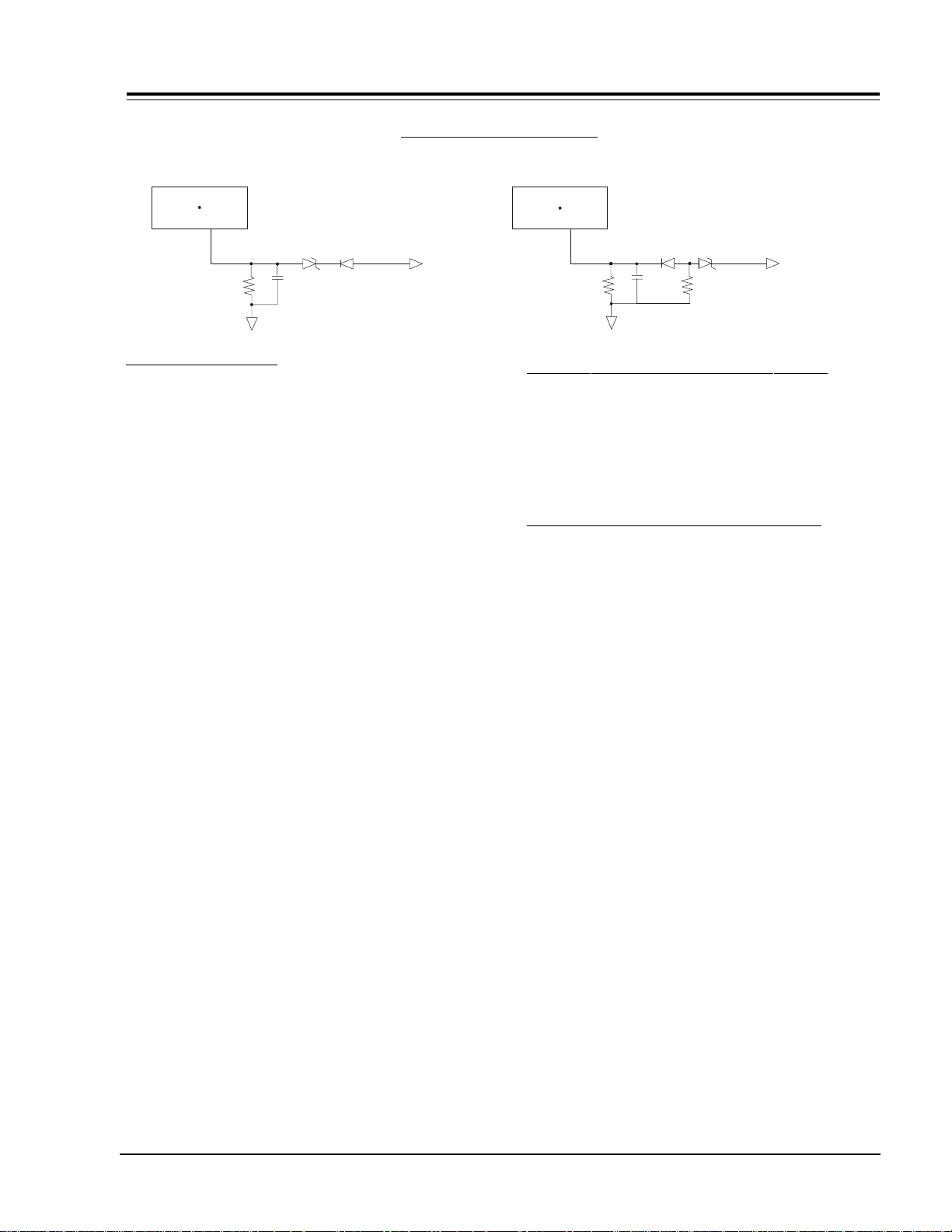
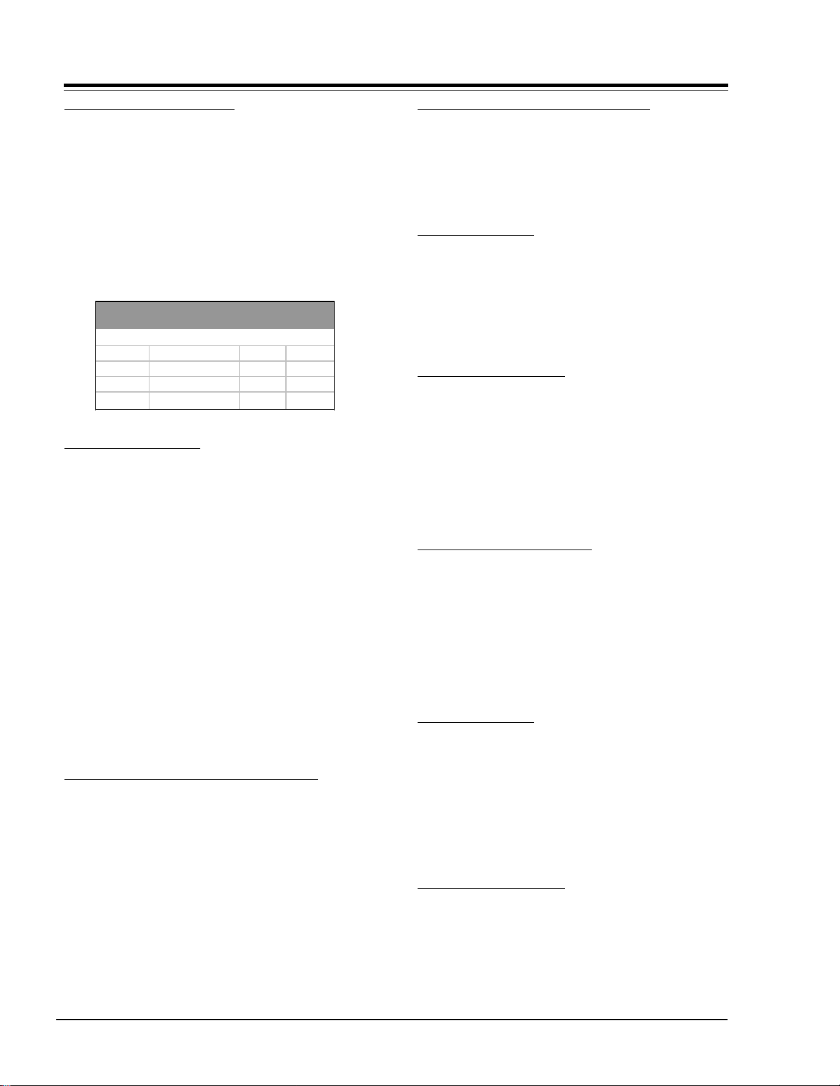
THEORY OF OPERATION (SHUTDOWN CIRCUIT)
The HV shutdown circuit appears on sheet 4 and sheet 5
of the schematics for 9-1869/71, 9-1789/91 and 91996/97 respectively. The basic HV shutdown circuit is
illustrated below.
This circuit basically monitors the sweep, pulse voltage
derived from the sweep transformer (TX3202 pins 7 & 9
in GA 19/20”; GA1 or TX3204 pins 5 & 6 in GA 25/27”;
GA2 and GA3. This voltage is rectified and applied to a
9.1 V zener diode (DX3003 in GA 19/20”; GA1 or ZDX3004
in GA 25/27”; GA2 & GA3). When the HV reaches its
maximum allowed value (see table below) the zener diode conducts, the voltage on pin 29 of the video processor (ICX2200) increases until it reaches the threshold voltage of 3.5 VDC, and shuts down the TV.
If the shutdown circuit has operated, the microcontroller
will prevent the TV from being turned on again, without
first having to unplug and plug the AC cord to reset the
microcontroller.
TIP: Make a momentary short circuit between the
OUTPUT and GND of the IC6002 (RESET CIRCUIT),
this will reset the microcontroller IC6000.
NOTE: In GA 19/20” or GA1 only, the R3212 is used for
the CRT heater and the shutdown circuit. So if
the video output board is unplugged from the
CRT, the voltage on pin 29 of ICX 2200 will be
increased, and the shut down circuit will activate.
If it is required to test the module without the
CRT or without the video output connected, then
add a load of 9 OHMS 5% 10W WIREWOUND
RESISTOR between pins 9 & 10 of the wireless
socket at the video output board.
CM150 3-1 GA - SERVICING
Page 2
SERVICING (continued)
(
)
HV MEASUREMENT PROCEDURE
Apply signal through the video generator, or tune the
TV color receiver to crosshatch pattern. Connect an accurate HV meter between the picture tube anode and
chassis ground. Access Video Menu and adjust Brightness and Contrast controls for minimum screen luminance.
Wait until the Video Menu or display disappear. Read HV
meter.
The HV maximum value for each chassis is specified in
the following table:
SCREEN B+ VDC HV NOM HV MAX
SIZE
19 130 +/- 0.8 26.5 27
20 130 +/- 0.8 26.5 27
25 124 +/- 0.5 28.5 29
27 124 +/- 0.5 28.5 29
0 BEAM
COMPONENT LEVEL REPAIR
KV KV
SERVICING THE MODULE
After a module is serviced, access the Service Menu and
check that all items are set properly. When the factory
mode is off only the first seven items in the Service
Menu are available. Place factory mode to 1 to see all
Service Menu adjustments. Be sure the factory mode is
set to 0, which is Off, when the Service Menu is exited.
Also make sure that item 04 LEVEL is set to match the
Level as indicated on the model number sticker on the
back of the set. The Level is changed by placing a short
across pins 3 and 4 of connector 4G9 on the main module. Then using the remote control, bring up the Service
Menu and select item 04. Press the adjust button to
make a change. Be sure to remove the shorting jumper
when the adjustment is completed. Confirm that item
#25 is set correctly to match the set being serviced! If
not, and No Audio condition will arise.When in the Private label mode, the set will only respond to IR code
121. .
SERVICING THE POWER SUPPLY GA1 19”/20”
NOTE: Use an isolation transformer when servicing 9-
1869, 1870, 1871, 1871-01 and 1950 chassis !!
STANDBY VOLTAGES
Check the Standby Voltage at the following points:
POWER ON (9-1869/70/71 AND 9-1950)
Keyboard input at IC6000 pin 7 and 8
IR input at IC6000 pin 15
Power “On” output at IC6000 pin 32
Base of QX3402 power supply switching transistor (about
0.7 volts).
+5 volts IC6000 pin 27
SWITCHED VOLTAGES
Turn the set On and check the Switched voltages at the
following points.
+130 volts DC at FX3402
+150 volts DC at CX3406
+180 volts DC at + of C3207
SWEEP DERIVED VOLTAGES
+5 volts DC at cathode of ZD3206
+9 volts DC at pin 3 of IC3201
+12 volts DC at + OF CX3213
+14 volts DC at + side of C3222
+25 volts DC at D3202 cathode
+180 volts DC at C3207
SERVICING THE POWER SUPPLY
GA2 & GA3 25”/27” 9-1789/90/91 & 9-1831
Standby Voltages
+150 volts DC at RX3404
+123 volts DC at CX3420
+15 volts DC at emitter Q3403
+5 volts DC at cathode of ZD3401
SWITCHED VOLTAGES
Turn set On and check the Switched voltages at the following points:
+5 volts DC at cathode of ZD3402
+9 volts DC at pin 3 of IC3431
+15 volts DC at collector of Q3404
+15 volts DC at collector of Q3403
+13 volts DC at CX3411
+12 volts DC at pin 1 of ICX3402
SWEEP DERIVED VOLTAGES
+25 volts DC at RX3242
+5 volts DC at pin 3 of ICX3402
CM150 3-2 GA - SERVICING
Page 3

SERVICING (continued)
+35 volts DC at CX3272
+215 volts DC at junction CX3296 and RX3277
CRT filament at pins 1 and 2 of connector 2F5
VIDEO PROCESSOR ICX2200
Key Operating Signals:
Composite Video out at pin 47
Video in at pin 37
Luminance in pin 43
Chroma in pin 45
Composite Audio out at pin 2
Horizontal Drive at pin 32
Vertical Drive at pin 24
Video Output Blue at 2C5 pin 3
Video Output Green at 2C5 pin 2
Video Output Red at 2C5 pin 1
B+ 9 volts pins 9, 46 and 48
Serial Data, Serial Clock pins 27 and 28
+25 volts pin 6
Vertical out pin 2
HORIZONTAL CIRCUIT
Horizontal drive to base of Q3201 predriver
Driver transformer output base of Q3202
Shutdown voltage anode ZFX3004
SERVICE ADJUSTMENTS (Mechanical)
1. Video Gain (19"/20" Models) Adjusts R9738 for 1
VERTICAL CIRCUIT
Vertical drive pulse pin 4
CM150 3-3 GA - SERVICING
Page 4
SERVICE ADJUSTMENTS
SERVICING (continued)
volt P-P at emitter of Q9706.
2. Audio Balance (19"/20" Models) Adjusts R9745 for
equal output at collectors of Q9701 and Q9703.
3. HORIZONTAL WIDTH (25"/27" Models) Adjusts R3249
for 1/2" overscan on both sides of the picture.
FOCUS ADJUSTMENT
Connect a color bar pattern to the receiver and adjust
the user controls for a good picture. Adjust the Focus
control, then push the menu button to video menu then
proceed until there is no distortion in the letters of the
menu.
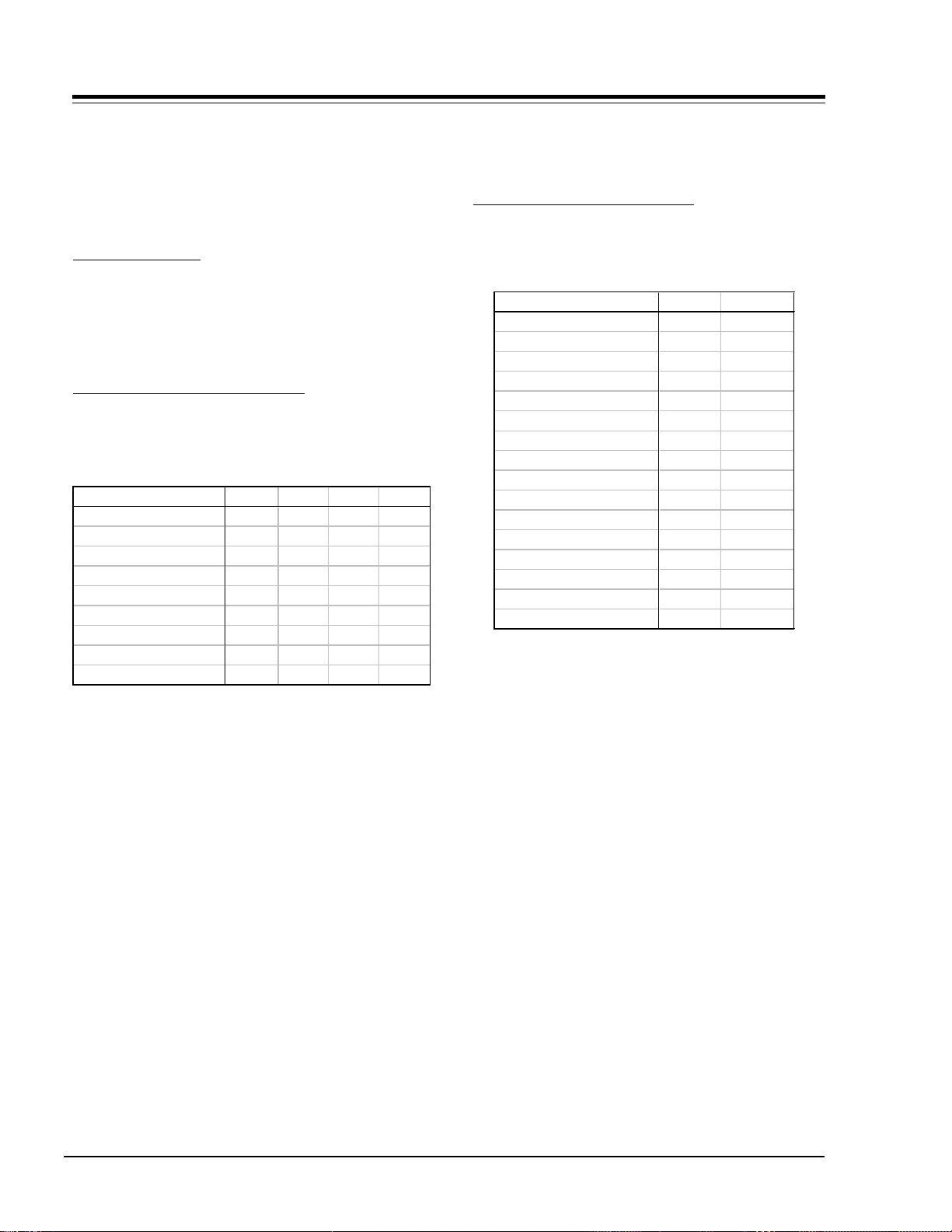
GA1/GA2 RGB CUTOFF (1164 Micro)
The G2 control must be adjusted before RGB drive.
1. If the main module or CRT has been replaced, set
items #23 G GAIN and #24 B GAIN, in the Service
GA1 GA2
Tube Size 19” 20” 25” 27”
Customer Contrast 0 0 0 0
RF Bright/Aux Bright 36 36 26 28
Customer Brightness 31 31 31 31
Red Cutoff 0 0 10 5
Green Cutoff 0 0 10 5
Blue Cutoff 0 0 10 5
Green Gain 90 90 90 90
Blue Gain 90 90 90 90
Menu, to the default setting for the correct screen
size as listed in the Service Menu (see above table).
2. Set color level to minimum and Tint to midrange.
3. Connect the output of an NTSC generator to the
antenna input of the receiver. Set the generator to
a pure white signal, chroma off.
4. Access the Service menu to gain access to the cutoff adjustments, (Factory mode item 00 must be set
to 1 to gain access to these adjustments).
5. Set items 22 R Cut, 23 G Cut and 24 B. Cut to the
values shown in the above table.
6. Carefully observe which color is predominant on the
CRT - DO NOT adjust the cutoff control for this color.
Adjust the other two cutoff controls for the best
white screen display.
7. Set the generator to a color bar patter and turn the
chroma off. Check that the set displays a good gray
scale from black to white. If black level is too high
readjust the item #9 RF Brightness.
8. Return the color level control to normal.
GA3 OF RGB CUTOFF (1305 Micro)
The G2 control must be adjusted before RGB drive.
1. If the main module or CRT has been replaced, select
GA3
Tube Size 25” 27”
Customer Contrast 0 0
RF Bright/Aux Bright 40 40
Customer Brightness 32 32
Color Temp Cool Cool
Red Cut 1 15 15
Green Cut 1 8 5
Blue Cut 1 12 12
Green Gain 1 95 100
Blue Gain 1 70 80
Color Temp Warm Warm
Red Cut 2 15 16
Green Cut 2 10 8
Blue Cut 2 17 16
Green Gain 2 70 75
Blue Gain 2 25 32
“Cool” in the user video menu under Color Temp.
Then set items #25 Gain 1 (Green gain cool) and
#26 B Gain 1 (Blue gain cool), in the Service Menu
to the default setting for the correct screen size as
listed in the Service Menu (see table above). Set
Color level to minimum and Tint to mid range.
2. Connect the output of an NTSC generator to the
antenna input of the receiver. Set the generator to
the Pure white signal, chroma off.
3. Access the Service Menu to gain access to the cutoff adjustments, (Factory mode item 00 must be set
to 1 to gain access to these adjustments).
4. Set items 22 R Cut, 23 G Cut, 24 B cut to the values
shown in the table.
5. Carefully observe which color is predominant on the
CRT. DO NOT adjust the cutoff control of this color.
Adjust the other two cutoff controls for the best
white screen display.
6. Set the generator to a color bar pattern and turn
CM150 3-4 GA - SERVICING
Page 5

SERVICING (continued)
the chroma Off. Check that the set displays a good
gray scale from black to white. If black level is too
high, readjust the item #9 RF Brightness.
7. Return the color level control to preset.
8. Select “Warm” in the user video menu under Color
Temp. Then adjust items 22 R Cut, 23 G Cut, 24 B
Cut, 25 G Gain 2 and 26 B Gain 2 according to the
following formulas:
R Cut2 Warm = R Cut 1 Cool +3
G Cut2 Warm = G Cut 1 Cool +3
B Cut2 Warm = B Cut 1 Cool +4
G Gain2 Warm = G Gain 1 Cool -25
B Gain2 Warm = B Gain Cool -48
9. Select “Cool” in the user video menu under Color
Temp.
CM150 3-5 GA - SERVICING
Page 6

SERVICING (continued)
PURITY & CONVERGENCE SETUP PROCEDURE
PRELIMINARY SETUP
1. Allow receiver to warm up for 15 to 20 minutes.
2. Degauss receiver.
3. Connect crosshatch generator to the receiver and
“rough in” the static (center) convergence.
Follow Convergence Status.
4. Adjust for best focus.
PURITY ADJUSTMENT
1. Purity tab positioning
Set the 2 pole purity tab together at 3 or 9 o’ clock
positions and the 4 and 6 pole purity tabs together
at 12 of 6 o’ clock positions.
2. Move yoke to maximum forward funnel position.
3. Now switch crosshatch generator to a red field.
4. Pull yoke towards rear of CRT neck centered or until
red raster is displayed.
5. If red raster is not displayed as a pure red field, adjust the 2 pole purity tabs until a pure field is obtained.
CONVERGENCE ADJUSTMENT
1. Release locking assembly
2. Connect crosshatch generator to the receiver and
adjust static (center) convergence as follows:
a.Adjust the 4 pole static control by moving the two
tabs separately to converge red and blue lines horizontally. Move the two tabs together around neck of
CRT in a 45º arc) from the top dead center position
to converge red and blue lines vertically.
b. After the 4 pole control has been adjusted to super-
impose the red and blue lines on top of one another.
Use the 6 pole static adjustment to place converged
red and blue lines over the green line. Move the two
tabs together around neck of CRT (in a 30º arc) from
the top dead center position to move the lines vertically. Adjusting the two tabs separately will move
converged beam to the left or right. Using a cross
hatch generator capable or producing individual fields,
adjust generator to produce a red field. Use purity
tabs to center a red stripe.
6. Check for proper yoke tilt setting.
Wedges’ Adhes ive Tape (3)
Deflection Yoke
Purity & Convergence
Magnet Assembly Unit
4 Pole
Yoke’s Glass Cloth Tape
Rubber Wedges (3)
6 Pole
Purity Magnet
CRT Ring Location Purity
Adjust Tabs Beam Movement
for Convergence
Ring
Pairs
6 Pole
Convergence
R&B over G
4 Pole
Convergence
R over B
Rotation direction
of Both Tabs
Opposite
Same
Opposite
Same
Movement of Red
and Blue Beams
B B
OR
R R
B
R
B
OR
R
B
OR
OR
B
R
B
R
R
BR
CM150 3-6 GA - SERVICING
Page 7

SERVICING (continued)
VERTICAL-TILT WEDGE ADJUSTMENT
The vertical lines at 6 and 12 o’clock are converged by
vertically tilting the yoke and inserting a wedge at the
top of the yoke until it is firmly seated between the CRT
glass and the horizontal coils.
HORIZONTAL-TILT WEDGE ADJUSTMENT
The vertical lines at 3 o’clock and 9 o’clock are converged
by horizontally tilting the yoke and inserting a wedge.
Adjust first at 4 or 8 o’clock, whichever has the larger
space, until the wedge is firmly seated between the CRT
glass and yoke coils. Then, insert the 3rd wedge in the
remaining horizontal tilt position until it is firmly seated
between the CRT glass and yoke coils. Convergence at
3 and 9 o’clock should be maintained during this operation.
When the 3 wedges are firmly installed and positioned
for acceptable convergence, lock the wedges in place by
applying a 2.5 inches long strip of tape across the tabs
of each wedge, firmly against the CRT glass. The CRT
glass surface should be clean and free of dust and other
foreign material.
UNUSUAL TILT CASE
There may be some instances where the picture tube
and yoke will require vertical tilt in the opposite (up)
direction to obtain convergence. In such cases, insert
the vertical tilt wedge at the bottom (6 o’clock) position. Follow through on the horizontal tilt adjustment
by using the 2 and 10 o’clock positions and secure each
wedge with a piece of tape, as described above.
IMPROVING CRT CORNER PURITY
CRTs that display corner purity problems even after following the service procedures can be modified with a
picture correction kit (P/N 949-50). The purity can be
improved by placing a picture-correction magnet (included in the kit) on the CRT funnel. Refer to the following modification steps and illustration to place the
magnet properly. Fully degauss the CRT before installing
correction magnets.
MODIFICATION
1. Place the magnet on the CRT funnel as shown in
the figure displayed below, in the quadrant
exhibiting impurity.
2. Rotate the magnet in place to the position shown
for best purity.
3. Place a piece of 1/2" by 2" long Fiberglass tape
over the magnet to hold it in place.
4. Degauss the CRT once magnet is in place to insure
that the magnet is not over the internal magnet
shield.
NOTE: If the magnet is placed over the internal
magnet shield, any apparent purity correction
will disappear after degaussing. Reposition
the correction magnet off the internal shield
and degauss again.
X
2" To 3"
MAGNET
Clamp and Scr ew
6 Pole Magnets
2 Pole Magnets
4 Pole Magnets
CM150 3-7 GA - SERVICING
Page 8

IC DESCRIPTIONS
IC DESCRIPTIONS
IC6001
4K Bit Serial EEPROM
221-00745-04
Pin Configuration
9&&
$
$
AT24C04
:3
AT M E L
$
*1'
CM150 3-8 GA - IC DESCRIPTIONS
6&/
6'$
Page 9

IC DESCRIPTIONS (continued)
Pin Configuration
221-00907
Pilot in
Pilot out
Loop filter
Loop filter
IN
Composite input
Ground
De-emphasis adjust
1
2
3
4
5
6
7
24
Pilot detector
Pilot detector
23
22
Resonator
21
Stereo/mono select
20
Stereo presence
19
VCC
18
BPF upper corner
1/2 VCC
1/2 VCC bypass
L-R output
L-R input
L-R gain adjust
CM150 3-9 GA - IC DESCRIPTIONS
8
9
10
11
12
17
BPF low er c o rn e r
16
Det. bypass
15
Det. time constant
14
Left output
13
Right output
L OUT
R OUT
Page 10

IC DESCRIPTIONS (continued)
Pin Definition
221-00981
Test Circuit
CM150 3-10 GA - IC DESCRIPTIONS
Page 11

IC DESCRIPTIONS (continued)
IC6000
CM150 3-11 GA - IC DESCRIPTIONS
Page 12

IC DESCRIPTIONS (continued)
HSYNC
VSYNC
P50/AD4
P41/INT2
P42/TIM2
P43/TIM3
P24/AD3
P25/AD2
P26/AD1
P27/AD5
P00/PWM4
P01/PWM5
P02/PWM6
1
2
3
4
5
6
7
8
9
10
11
12
13
IC6000
221-01305
52
51
50
49
48
47
46
45
44
43
42
41
40
P52/R
P53/G
P54/B
P55/OUT1
P04/PWMO
P05/PWM1
P06/PWM2
P07/PWM3
P20
P21
P22
P23
P10/OUT 2
P17/SIN
P44/INT1
P45/SOUT
P46/SCLK
AVCC
HLF/AD6
P72/RVCO
P71/VHOLD
P70/CVIN
CNVSS
XIN
XOUT
VSS
14
15
16
17
18
19
20
21
22
23
24
25
26
39
38
37
36
35
34
33
32
31
30
29
28
27
P11/SCL1
P12/SCL1
P13/SDA1
P14/SDA2
P15
P16/INT3
P03
P30
P31
RESET
P64/OSC2/XCOUT
P63/OSC1/XCIN
VSS
CM150 3-12 GA - IC DESCRIPTIONS
 Loading...