

Page 1

SECTION 2
INSTALLERS MENU
Figure 1
1164-01/02 Micro opening
display.
1305 Micro opening display.
INSTALLER’S MENU
ACCESS
Access the Service Menu by using the remote control or
the keyboard on the front of the set.
With the remote: Press and hold MENU key until user
menu displays disappears, then press 9, 8, 7, 6 and
ENTER. This will access the 03 H Pos item of the Service
Menu.
Models with 6 button Keyboard: Press and hold Menu
until User Menu display disappears. Immediately press
Volume Up and Channel Down simultaneously.
Models with 10 button keyboard: Press and hold MENU
until the user menu disappears. Immediately press the
Adj. Right and Channel Up keys simultaneously.
NOTE: Entry into and exit from the Service Menu will
automatically unblock all parental control.
To exit Service Menu, press ENTER key. Entry into and
exit from the Service Menu, will automatically un-block
all parental Control.
DISPLAY
The GA Chassis uses three different microcontrollers
(IC6000): 221-01164-01, 221-01164-02, or 22101305-01. When the Factory menu is accessed, the
opening display screen will show the microcontroller on
the top line. It will look as shown in Figure 1 or 2. The
bar at the top indicates the part number of the software
in the set. The bar at the bottom has a date and number.
The date on the left indicates the date the module went
through the factory. The number on the right indicates
the module has been tested.
The first seven menu items 00 through 06 will be the
same for each micro. Items 07 through the end will be
different on each micro.
When Service Menu appears, it will always appear on
third item H Pos. Use SELECT key to toggle through all
of the adjustments.
Figure 2
Figure 3
1164-01/02 Factory mode on
opening display.
1164-01/02 MICRO
00 F MODE: (Factory Mode) Use Select key to select
item #00, which is the first item in the Service Menu,
the Factory mode. This item is used by the factory
when the module is being tested. In the field, this
item should always be left “off”. Zero is “Off”!
When the factory mode is Off, only the first seven
items in the Service Menu can be accessed. When the
factory mode is set to 1, all menu items will be available. Also they will appear on the screen one at a
time at the top left of the screen, as shown in Figure
3.
If the factory mode is “On”, a pair of dashes will ap-
pear at the top of the Customer Set Up Menu. On
other menus a number corresponding to the setting
of a high lighted item will be shown. This is a quick
way a technician can tell that the factory mode is on.
Other unusual things also happen when the factory
mode in “On”, for example, the AC power on feature is
always enabled regardless of the setting of “AC On” in
the Service Menu. The set will automatically come On
when AC is applied. In addition, when the factory
mode is “On”, the Service Menu can be accessed on
10 button key boards by pressing simultaneously the
RIGHT ADJ. and CHANNEL UP buttons. On 6 button
keyboards press VOLUME UP and CHANNEL DOWN buttons. Otherwise the hand control must be used to reenter the Service Menu to turn the factory mode off.
The factory mode can also be turned off by adjusting
the setting of the clock, or running the Auto Program feature in the customer Set Up menu.
01 Pre Px: Used to store the customer menu adjust-
ments in the non-volatile memory of the EAROM. Settings for Contrasts, Brightness, Color and Tint are
stored in this manner. 0 is custom and 1 is Pre-set
stored.
02 V Pos: Moves On Screen Displays vertically. Range is
0 - 24. Generally set at 10.
CM150 2-1 GA - INSTALLER MENUS
Page 2
INSTALLERS MENU 221-01164-01/02 (continued)
03 H Pos: Moves On Screen Displays horizontally. Range
is 0 - 13. Generally set at 9.
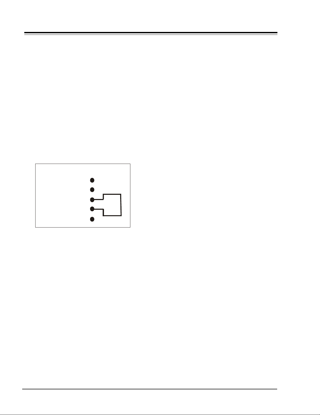
04 Level: There are three positions, 0, 1 and 2. The
three different positions are used at the factory to
program the module for the correct features. In
order to change the level, short pins 3 and 4
together on connector 4G9 on the main module.
The connector is located on the left hand side of
the module just to the left of the Micro IC6000 on
19" and 20" sets. On the 25" and 27" sets it is on
the left edge of the module. Use the Adjust button
to change the level. Connector 4G9 is located on
the left hand side of the module near the micro.
NOTE: BE CAREFUL!! IF THE WRONG PINS ARE SHORTED,
THE MODULE CAN POSSIBLY BE DAMAGED.
NOTE: BE SURE TO REMOVE THE JUMPER AFTER THE LEVEL
HAS BEEN SET.
4G9 CONNECTOR
DATA
CLOCK
CONTROL
+5 VOLTS
GROUND
1
2
3
4
5
TEST
POINT
Level 0 and 2 is used for Private Label sets. Level 1
and 2 are used for Zenith sets. In the private label
mode the IR code is 21 or 121.
05 Band: There are eight positions. 0 is Broadcast
fixed, 1 is CATV afc, 2 is HRC afc, 3 is ICC afc, 4 is
Broadcast afc, 5 is CATV fixed, 6 is HRC fixed, and 7
is ICC fixed.
06 AC On: There are two positions, 0 is off and 1 is AC
ON. In On position set will turn on and off when AC
power is applied and removed.
11 V Size: (Vertical Size) Adjusts the size of the
picture vertically. Range is 0 - 63.
12 V Phase: (Vertical Phase) Shifts the picture
vertically. Range is 0 - 7.
13 H Phase: (Horizontal Phase) Shifts the picture
horizontally. Range is 0 - 31.
14 AudLvl: (Audio Level) Sets the gain for the
Composite Audio from Video processor. Range is
0 - 63.
15 RF Agc: Range is 0 - 63. Tune in weakest channel
and adjust for a snow free picture.
16 H Afc: There are two settings 0 and 1.
17 WhComp: (White Compression) There are two
settings 0 and 1.
18 60 HzSW: (60 Hertz Switched) Range is 0 - 3.
19 PifVco: (PIF Voltage Controlled Oscillator) Range is
2 - 127.
ITEMS #20 THROUGH 24 ARE FOR B&W TRACKING
20 R Cut: Range is 0 - 254.
21 G Cut: Range is 0 - 254.
22 B Cut: Range is 0 - 254.
23 G Gain: Range is 0 - 254.
24 B Gain: Range is 0 - 254.
25 C Type: (Chassis Type) There are six selections, 0
to 5. 0 is mono, 1 is mono W/Aux, 2 is Non MTS
Stereo, 3 is Non MTS W/Aux, 4 is MTS chassis and 5
is MTS chassis W/Aux.
26 Scroll: Selects the method the User menus will
appear on the screen. Scroll Off is 0.
27 6 Keys: Set to 1 for the 6 key keyboard. Set to 0
for the 10 key keyboard.
1164-01 MICROCONTROLLER
28 SpkSw: Range is 0 - 1. This item is not being used.
29 5 Jacks: Range is 0 - 1. Set to 0.
30 St & Sap: Range is 0 - 1. Set to 0.
1164-01 AND 1164-02 MICROCONTOLLER
07 Rf Bpf: (Rf Bandpass) Range is 0 - 1.
08 3.58T: 3.58 MHz trap. Range is 0 - 1.
09 RF Brt: (RF Brightness) Sets adjustment range of
the customer control, for brightness in RF mode.
1164-02 MICROCONTROLLER
28 SpkrSw: Range is 0 - 1. This item is not being
used.
29 Surf: Range is 0 - 1. This item is not being used.
30 Vcurve: Adds Speakers in Set-up menu, Zero is off.
Range is 0 - 63.
10 Aux Brt: (Auxiliary Brightness) Sets adjustment
range of the customer control, for brightness in
AUX mode. Range is 0 - 63.
CM150 2-2 GA - INSTALLER MENUS
Page 3
INSTALLERS MENU 221-01164-01/02 (continued)
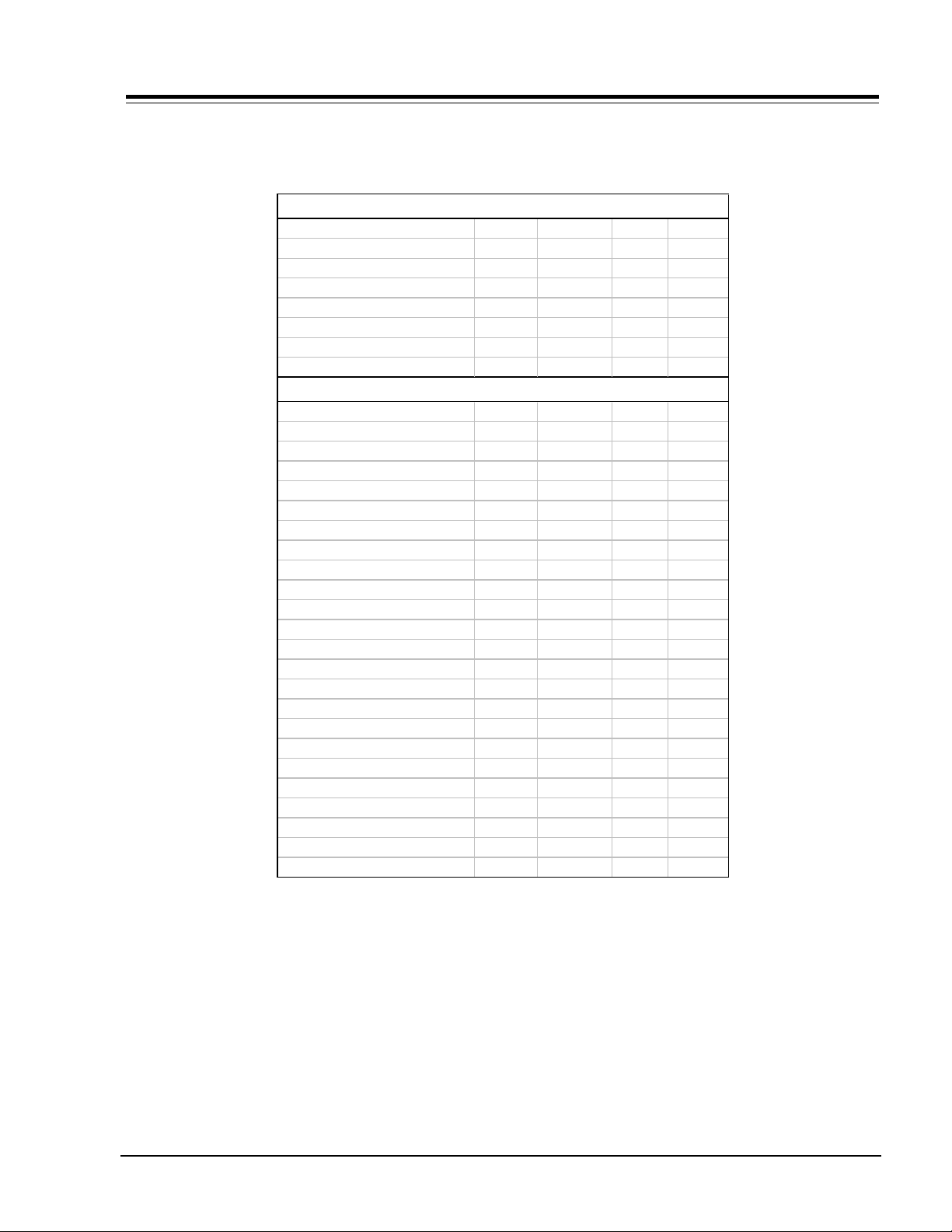
FACTORY RECOMMENDED SETTINGS 221-01164-01
Factory Mode 0 (Blue)
ITEM RANGE 19/20" 25” 27"
00 F Mode 0-1 0 0 0
01 Pre Px 0-1 1 1 1
02 V Pos 0-24 10 7 7
03 H Pos 0-13 10 10 10
04 Level 0-2 1* 1* 1*
05 Band 0-7 0 0 0
06 AC On 1 0 0 0
Factory Mode 1 (Black)
07 RF Bpf 0-1 1 1
08 3.58T 0-1 1 1 1
09 RF Brt 0-63 32 32 32
10 Aux Brt 0-63 32 32 32
11 V. Size 0-63 36 36 36
12 V. Phase 0-7 5 2 2
13 H. Phase 0-31 19 19 18
14 Aud Lvl 0-63 46 46 46
15 RF Agc 0-63 31 31 33
16 H Afc 0-1 1 1 1
17 WhComp 0-1 0 0 0
18 60 HzSw 0-3 2 2 2
19 PifVco 0-127 31 31 31
20 R Cut 0-254 0 10 5
21 G Cut 0-254 0 10 5
22 B Cut 0-254 0 10 5
23 G Gain 0-254 90 90 90
24 B Gain 0-254 90 90 90
25 C Type 0-5 2 2 2
26 Scroll 0-1 1 1 1
27 6 Keys 0-1 1 1 1
28 SpkrSw 0-1 0 0 0
29 5 Jack 0-1 0 0 0
30 St & Sap 0-1 0 0 0
* 04 Level 0 and 1 are used for Zenith sets. Level 0 is Private Label.
CM150 2-3 GA - INSTALLER MENUS
Page 4

INSTALLERS MENU 221-01164-01/02 (continued)
FACTORY RECOMMENDED SETTINGS 221-01164-02
Factory Mode 0 (Blue)
ITEM RANGE 19/20" 25” 27"
00 F Mode 0-1 0 0 0
01 Pre Px 0-1 1 1 1
02 V Pos 0-24 10 7 7
03 H Pos 0-13 10 10 10
04 Level 0-2 1* 1* 1*
05 Band 0-7 0 0 0
06 AC On 1 0 0 0
Factory Mode 1 (Black)
07 RF Bpf 0-1 1 1
08 3.58T 0-1 1 1 1
09 RF Brt 0-63 32 32 32
10 Aux Brt 0-63 32 32 32
11 V. Size 0-63 36 36 36
12 V. Phase 0-7 5 2 2
13 H. Phase 0-31 19 19 18
14 Aud Lvl 0-63 46 46 46
15 RF Agc 0-63 31 31 33
16 H Afc 0-1 1 1 1
17 WhComp 0-1 0 0 0
18 60 HzSw 0-3 2 2 2
19 PifVco 0-127 31 31 31
20 R Cut 0-254 0 10 5
21 G Cut 0-254 0 10 5
22 B Cut 0-254 0 10 5
23 G Gain 0-254 90 90 90
24 B Gain 0-254 90 90 90
25 C Type 0-5 2 2 2
26 Scroll 0-1 1 1 1
27 6 Keys 0-1 1 1 1
28 SpkrSw 0-1 0 0 0
29 Surf 0-1 0 0 0
30 Vcurve 0-1 0 0 0
* 04 Level 0 and 1 are used for Zenith sets. Level 0 is Private Label.
CM150 2-4 GA - INSTALLER MENUS
Page 5

INSTALLERS MENU 221-01305-01
1305 MICRO
00 F MODE: (Factory Mode) Use Select key to select
item #00, which is the first item in the Service Menu,
the Factory mode. This item is used by the factory
when the module is being tested. In the field, this
item should always be left “off”. Zero is “Off”!
When the factory mode is Off, only the first seven
items in the Service Menu can be accessed. When the
factory mode is set to 1, all menu items will be available. Also they will appear on the screen one at a
time at the top left of the screen, as shown in Figure
3.
If the factory mode is “On”, a pair of dashes will ap-
pear at the top of the Customer Set Up Menu. On
other menus a number corresponding to the setting
of a high lighted item will be shown. This is a quick
way a technician can tell that the factory mode is on.
Other unusual things also happen when the factory
mode in “On”, for example, the AC power on feature is
always enabled regardless of the setting of “AC On” in
the Service Menu. The set will automatically come On
when AC is applied. In addition, when the factory
mode is “On”, the Service Menu can be accessed on
10 button key boards by pressing simultaneously the
RIGHT ADJ. and CHANNEL UP buttons. On 6 button
keyboards press VOLUME UP and CHANNEL DOWN buttons. Otherwise the hand control must be used to reenter the Service Menu to turn the factory mode off.
The factory mode can also be turned off by adjusting
the setting of the clock, or running the Auto Pro-
gram feature in the customer Set Up menu.
01 Pre Px: Used to store the customer menu adjust-
ments in the non-volatile memory of the EAROM. Settings for Contrasts, Brightness, Color and Tint are
stored in this manner. 0 is custom and 1 is Pre-set
stored.
02 V Pos: Moves On Screen Displays vertically. Range is
0 - 24. Generally set at 10.
03 H Pos: Moves On Screen Displays horizontally. Range
is 0 - 13. Generally set at 9.
04 Level: There are three positions, 0, 1 and 2. The
three different positions are used at the factory to
program the module for the correct features. In order
to change the level, short pins 3 and 4 together on
connector 4G9 on the main module. The connector is
located on the left hand side of the module just to
the left of the Micro IC6000 on 19" and 20" sets. On
the 25" and 27" sets it is on the left edge of the
module. Use the Adjust button to change the level.
Connector 4G9 is located on the left hand side of the
module near the micro.
NOTE: BE CAREFUL!! IF THE WRONG PINS ARE SHORTED,
THE MODULE CAN POSSIBLY BE DAMAGED.
NOTE: BE SURE TO REMOVE THE JUMPER AFTER THE LEVEL
HAS BEEN SET.
4G9 CONNECTOR
DATA
CLOCK
CONTROL
+5 VOLTS
GROUND
1
2
3
4
5
TEST
POINT
Level 0 and 2 is used for Private Label sets. Level 1
and 2 are used for Zenith sets. In the private label
mode the IR code is 21 or 121.
05 Band: There are eight positions. 0 is Broadcast fixed,
1 is CATV afc, 2 is HRC afc, 3 is ICC afc, 4 is Broadcast
afc, 5 is CATV fixed, 6 is HRC fixed, and 7 is ICC fixed.
06 AC On: There are two positions, 0 is off and 1 is AC
ON. In On position set will turn on and off when AC
power is applied and removed.
07 Rf Bpf: (RF bandpass) Range is 0 - 1.
08 3.58T: 3.58 Mhz trap. Range is 0 - 1.
09 Rf Brt: (RF Brightness) Set the adjustment range of
customer control for brightness in RF mode. Range
is 0 - 63.
10 Ax Brt: (Aux Brightness) Sets adjustment range of
customer control for brightness in the AUX mode.
Range is 0 - 63.
11 MaxCon: (Max Contrast) Set adjustment range of
customer control for contrast. Range is 0 - 63.
12 V. Size: (Vertical Size) Adjusts size of picture
vertically. Range is 0 - 254.
13 H. Size: (Horizontal Size) Adjusts size of picture
horizontally. Range is 0 - 254.
14 V. Phase: (Vertical Phase) Shifts picture vertically.
Range is 0 - 7.
15 H. Phase: (Horizontal Phase) shits picture verti-
cally. Range is 0 - 7.
16 AudLvl: (Audio Level) Set gain for Composite
Audio from Video processor. Range is 0 - 63.
17 RF Agc: Range is 0 - 63.
CM150 2-5 GA - INSTALLER MENUS
Page 6

INSTALLERS MENU 221-01305-01 (continued)
18 H Afc: There are two setting 0 and 1. Setting is
usually 1.
19 WhComp: (White Compression) There are two
settings 0 and 1. Setting is 0.
20 60hzSw: (60 Hertz compression) There are two
settings 0 and 1. Setting is 0.
21 PifVco: (PIF Voltage Controlled Oscillator)
Range is 0 - 127.
Items # 22 through #26 are for B&W tracking
22 R Cut: Range is 0- 254.
23 G Cut: Range is 0 - 254.
24 B Cut: Range is 0 - 254.
25 G Gain: (Green Gain) Range is 0 - 254.
26 B Gain: (Blue Gain) Range is 0 - 254.
27 Scroll: Selects the method the User Menus that will
appear on the screen. Scroll Off is 1, 1 is On.
28 6 Keys: Set to 1 for the 6 button keyboard.
29 A Att: (Audio Attenuator) Range is 0 - 15.
30 A VCO: (Audio Voltage Controlled Oscillator)
Range is 0 - 63.
31 A Fltr: (Audio Filter) Range is 0 - 63.
32 Spctrl: High Frequency separation. Range is
0 - 63.
33 W Band: (Wide Band Low Frequency Separation)
Range is 0 - 63.
34 PiP Z1: Adjusts horizontal position of the insert
picture on left side.
35 PiP Y1: Adjusts vertical position of the insert
picture on left side.
36 PiP X2: Adjusts horizontal position of the insert on
right side.
37 PiP Y2: Adjust vertical position of the insert
picture on right side.
38 PiP Ras: (Picture in Picture Raster) Range is 0
- 255.
39 PiP Sw: (Pip Switch Delay) Used to center PIP
Boarder and PIP picture in the horizontal direction.
Range is 0 - 15.
40 PiPLud: (PIP Luminance Delay) Used to match
Luma and Chroma of inset picture. Range is 0 - 7.
41 PIP Tof: (PIP Tint level register) Range is 0 - 63.
42 C. In OSDC: On screen dispalay internal oscillator.
Range is 0 - 1.
43 OSD FR: On screen display frame. Range is 0 - 1.
CM150 2-6 GA - INSTALLER MENUS
Page 7

INSTALLERS MENU 221-01305-01 (continued)
FACTORY RECOMMENDED SETTINGS 221-01305-01
General Setting (Blue) Factory Mode 0
ITEM RANGE 25” 27"
00 F Mode 0-1 0 0
01 Pre Px 0-1 1 1
02 V Pos 0-24 14 17
03 H Pos 0-13 6 8
04 Level 0-2 0* 0*
05 Band 0-7 0** 0**
06 AC On 1 0 0
Technical Settings (Black) Factory Mode 1
07 RF Bpf 0-1 1 1
08 3.58T 0-1 1 1
09 RF Brt 0-63 32 32
10 Aux Brt 0-63 32 32
11 MaxCon 0-63 63 63
12 V. Phase 0-254 86 53
13 H. Phase 0-254 110 104
14 V. Phase 0-7 3 1
15 H. Phase 0-31 15 20
16 Aud Lvl 0-63 46 46
17 RF Agc 0-63 31 31
18 H Afc 0-1 1 1
19 WhComp 0-1 0 0
20 60hz Sw 0-3 2 2
21 PifVco 0-127 32 32
Color Temp Cool Starting Values
22 R Cut 0-254 5 5
23 G Cut 0-254 0 0
24 B Cut 0-254 10 10
25 G Gain 0-254 66 66
26 B Gain 0-254 14 14
27 Scroll 0-1 1 1
28 6 keys 0-1 1 1
29 A Att 0-1 9 9
30 A VCoc 0-15 31 31
31 A Fltr 0-63 31 31
32 Spctrl 0-63 31 31
33 W Band 0-63 31 31
34 PiP X1 0-63 7 7
35 PiP Y1 0-63 5 5
36 PiP X2 0-63 49 49
37 PiP Y2 0-63 32 32
38 PiP Ras 0-254 68 68
39 PiP Sw 0-15 8 8
40 PiP Lud 0-7 2 2
41 PiP TOF 0-63 3 3
42 C. In OSDC 0-1 0 0
43 OSD FR 0-1 0 0
CM150 2-7 GA - INSTALLER MENUS
Page 8

 Loading...