

Page 1

Zenith Tudor
Single point open outlet (vented) water heaters
p Tud over-sink water heater
216666666 Zip Tudor 5 Litre under-sink water heater
216666666666utor 10 Litre under-sink water heate
99032 Telescopic Spout accessory for 21000 / 21020
990399999994 Mono vented mixer tap fo66r 21010 / 21030
919111088lo vented mixer tap for 21010 / 21030
99050 Hero vented mixer tap for 21010 / 21030
ä
Installation & Operating Instructions
21600 Zenith Tudor 5 Litre over-sink water heater
21620 Zenith Tudor 10 Litre over-sink water heater
21610 Zenith Tudor 5 Litre under-sink water heater
21630 Zenith Tudor 10 Litre under-sink water heater
99032 Telescopic Spout accessory for 21600 / 21620
99079 Mono vented mixer tap for 21610 / 21630
99080 Solo vented mixer tap for 21610 / 21630
99081 Hero vented mixer tap for 21610 / 21630
Page 2
Page 2 Zenithip Tudor - Installation & Operating Instructions - 81333 - May 2003
Read These Warnings First
Tapware
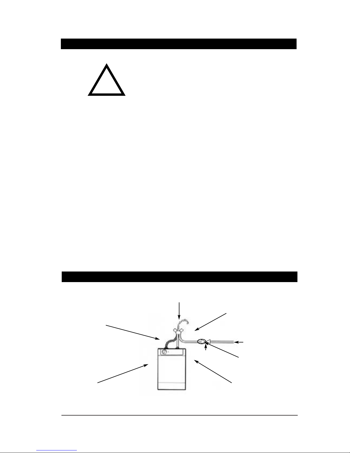
# Quick Installation Guide
Please read all installation requirements, installation procedures and
precautions before installing any Zenith Tudor water heater.
Never attempt to install any Zenith Tudor water heater without reading all of the
applicable instructions.
Zenith Tudor water heaters are open outlet (vented) water heaters and must not
be installed in the same way as mains pressure type water heaters.
The outlet from any Zenith Tudor water heater must be connected directly to an
outlet spout on the sink and must not be obstructed by a tap or valve or in any
other way.
The water flow is controlled by a cold water tap connected before the water
heater. Cold water pushes hot water out of the tank when the cold water tap is
turned ON. Any such cold water tap should be labelled HOT.
This water heater must not be connected to more than one outlet.
All plumbing connections must be made in accordance with AS3500.
The heater is intended only for indoor use and should never be installed
outdoors or be exposed to the elements of nature.
Over-sink and under-sink models are NOT interchangeable.
Children should be supervised to ensure they do not play with the heater.
The heater is unsuited for use by children or infirm people without supervision.
If the power supply cord is damaged it must be replaced by a Zenith Service
Provider or a qualified electrician.
Do not remove the cover of the heater under any circumstances without first
isolating the heater from the power supply.
Outlet temperature should never be set to less than 60°C without due regard to
regulations governing the storage temperature of hot water.
!
Step One
Install approved vented tapware
see page 3
Step Two
Position heater <1000 mm from tap
see page 4
Step Three
Fasten heater to wall
see page 4
Step Four
Connecting
see page 4
Step Five
Commissioning
see page 4
before turning power on
Tudor Heater
Isolation valve
Cold Water Supply
Flow Restrictor
Page 2 Zenith Tudor - Installation & Operating Instructions - 81333 - July - 2004
Page 3

Before installing, ensure that the following are available:
Installation Requirements
Before installing, ensure that the following are available:
a) sufficient space to position the heater so there is 270 mm clear access
under the heater (over-sink models) or 270mm above (under-sink).
b) standard 10 amp 240 volt power outlet within 1500 mm of the heater
c) cold water supply with a minimum working pressure of 50 kPa and a
maximum working pressure of 750 kPa.
If pressure may exceed 750 kPa, a pressure limiting valve must be installed.
Under-sink models must be installed beneath approved vented mixer taps
requiring a single mounting point on a sink, basin or tub.
Water pressure under 100 kPa may be sufficient for over-sink heaters but may
not operate under-sink mixer taps satisfactorily.
Step One - Tapware
Over-sink models must be installed with an inlet valve to control the flow from
the water supply to the heater. No valve is supplied with the heater. The water
supply and valve should be connected after the fastening the heater to the wall.
Over-sink models are supplied with a 300 mm swivel spout. An 300 mm to
600 mm telescopic swivel spout (99032) is available as an optional extra.
Under-sink models must be installed with approved vented tapware. It is
advisable to fit the tap to the sink before mounting the heater to the wall
beneath the sink.
1. Ensure that the flexible tubes are firmly attached to the base of the tap body.
2. Flush water supply pipes thoroughly to remove any silt or fines.
3. Fasten the tap body to the sink using the bolt & plate system provided.
4. Connect red flexible tube (from tap base "C") to the heater outlet.
5. Insert flow restrictor provided to the free end of blue flexible tube "A"
ONLY IF the water pressure is likely to exceed 250 kPa. Otherwise discard
restrictor.
6. Connect blue flexible tube (from tap base "B" ) to the heater inlet.
7. Connect blue flexible tube (from tap base "A") to the cold water supply.
Do not dismantle the assembled ta
Note: If replacing an existing open outlet (vented) water heater an isolation valve
must be fitted to the incoming water supply and a 7L/min flow restrictor fitted
at the isolation valve outlet. It is essential to establish that any existing tapware
is vented.
p body during installation. Mixer taps are
factory tested and sealed to provide optimum performance.
To adjust water temperature delivered by Solo and Hero mixer taps, see
instructions on page 7. Such adjustments should be made only by a qualified
technician.
Cold Water
Supply to Heater
Fixing Bolt
HERO MIXER
Cold Water
Supply from Tap
SOLO MIXER
Fixing Bolt
MONO MIXER
Cold Water Supply to
Heater
Cold Water
Supply from Tap
Hot Water
Supply from Heater
A
B
C
C
A
B
Zenithp Tudor - Installation & Operating Instructions - 81333 - May 2003 Page 3
Before installing, ensure that the following are available:
Installation Procedure
Hot Water
Supply from Heater
Zenith Tudor - Installation & Operating Instructions - 81333 - July - 2004 Page 3
Page 4

Page 4 Zenithip Tudor - Installation & Operating Instructions - 81333 - May 2003
Installation Procedure continued
Step Two - Positioning
Over-sink heaters should be installed so that the outlet spout drains to a sink
or basin, and with a clearance of 270 mm beneath the heater to allow for
service access.
Under-sink heaters should be installed a closely as possible to directly below
the outlet tap with a clearance of 270 mm above the heater.
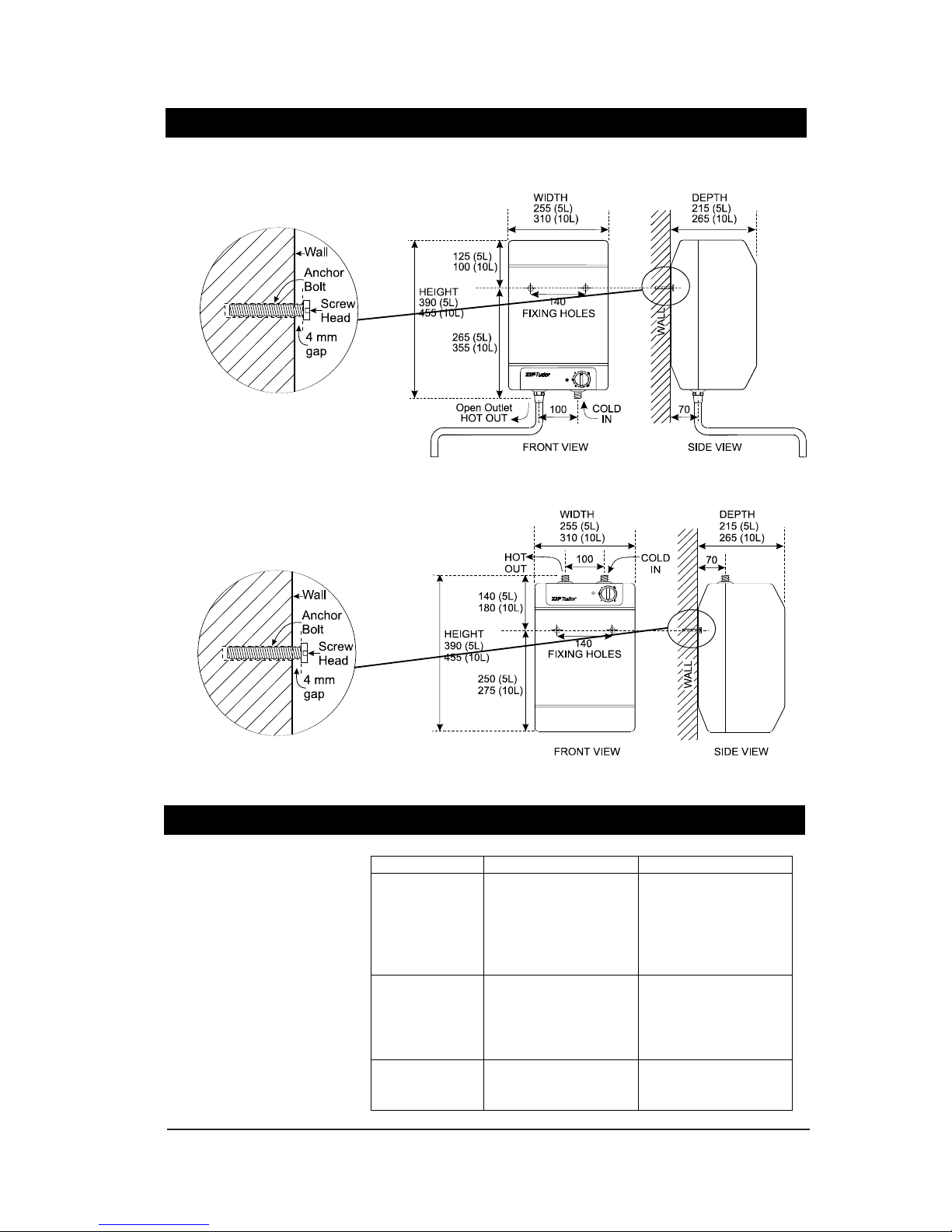
Step Three - Fastening
It is not necessary to remove the case of the heater during installation.
The heater must be wall mounted with two fixing screws as shown in the
diagram on page 5. Fixing screws must have the strength to support the filled
heater.
The fixing screws are to protrude 4 mm from the wall as shown in the diagram
on page 5 so as to fit into keyhole slots provided on the rear of the heater.
Step Four - Connecting
On over-sink models, the inlet and outlet are located on the base of the heater.
On under-sink models, the inlet and outlet are located on the top of the heater.
All Zenith Tudor water connections are via 15 mm compression fittings and must
be made strictly as shown in the diagrams.
Over-sink models are supplied with a 300 mm open outlet spout, and must
also be fitted with an isolation valve on the cold water side. A valve is not
supplied with the heater and must be supplied and fitted by the installer.
Under-sink models must be installed with approved vented tapware regulating
the incoming water supply which displaces the hot water from the heater so it
discharges through the open vented spout incorporated into the tap mounted
on the basin or sink.
The use of tapware other than approved vented tapware is dangerous.
Each heater is equipped with a 1600 mm power cord and plug and should be
connected to a standard 10 amp power outlet located adjacent to the heater.
Do not turn the power ON until the heater is filled with water and air is purged
from the heater.
Step Five - Commissioning
Fill the heater tank and purge air from the heater by turning the water supply
ON and running water through the heater until it flows smoothly. Turn the water
supply OFF and turn the power supply ON. The heater will then run through its
heating cycle.
During the heating cycle, drips fall from the delivery spout or tap.
Dripping will cease when the heating cycle is completed and the stored water
temperature has reached the level set by the user.
Model Weight(kg)
Empty Full
Five Litre
over-sink 3.5 8.5
Ten Litre
under-sink 4.0 14.0
Five Litre
over-sink 3.5 8.5
Ten Litre
under-sink 4.0 14.0
Page 4 Zenith Tudor - Installation & Operating Instructions - 81333 - July - 2004
Page 5
Installation Procedure Continued
Problem Solving
Fault Possible cause Solution
No heat No power
Faulty element
Faulty thermostat
Faulty cutout
Tripped overlaod
Check power supply
Contact Zenith
No water No supply
Blockage
Faulty thermostat
Faulty cut out
Check water supply
Contact Zenith
No indicator Faulty LED
Faulty connection
Contact Zenith
Zip Tudor - Installation & Operating Instructions - 81333 - May 2003 Page 5
Over-Sink
Under-Sink
Zenith Tudor - Installation & Operating Instructions - 81333 - July - 2004 Page 5
Page 6
Page 6 Zenithenithdor - Installation & Operating Instructions - 81333 - May 20
Operating Procedures
Water Temperature
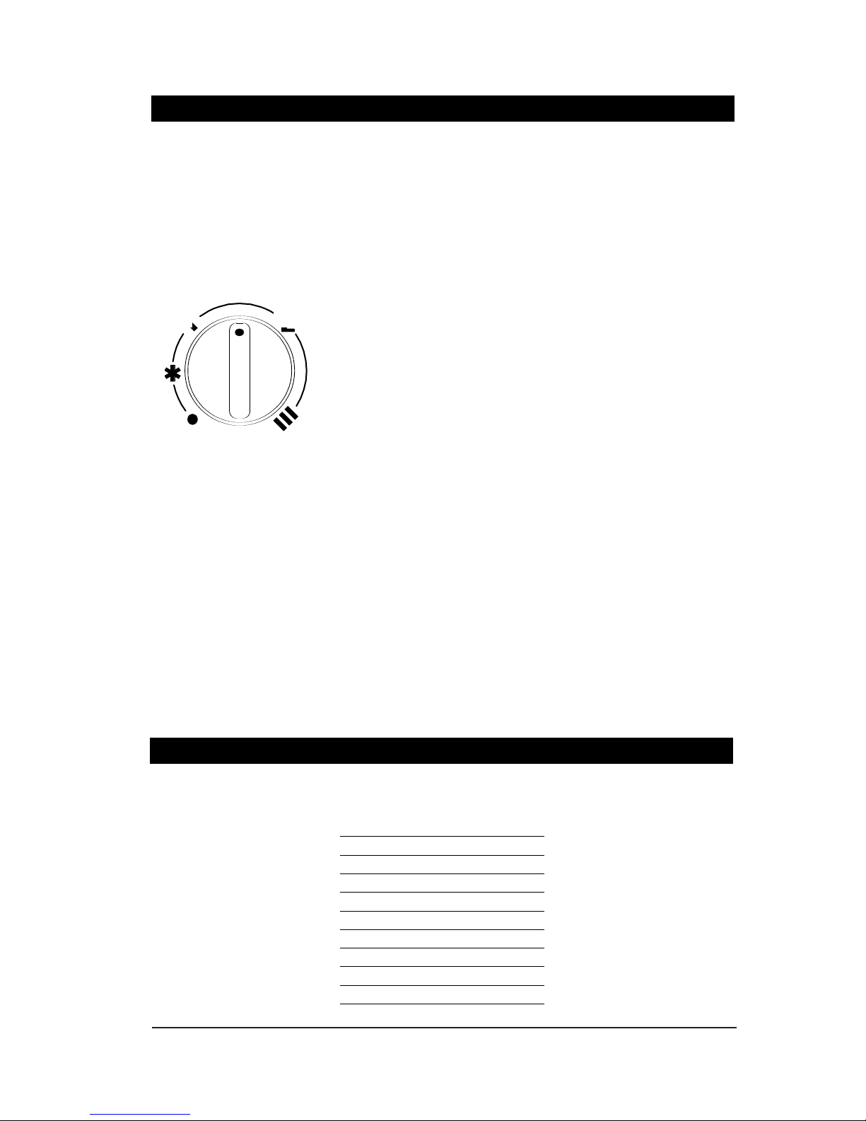
Zenith Tudor water heaters are fully automatic, and may be left switched ON
under the control of the variable thermostat.
Nominal operating temperature can be varied from about 30°C to about 80°C.
Temperature should not be set to less than 60°C without due regard to
regulations governing the storage temperature of hot water.
Economy Setting
The economy setting "E" will maintain stored water temperature at
approximately 60°C. At the "E" setting, the temperature control locates into a
set position and a slight resistance will be felt when rotating the temperature
control beyond that setting. This measure is to help ensure that higher
temperatures are only selected deliberately.
Frost Protection
If the heater is located where ambient air temperature could fall below 5°C
when the heater is not in use, the "anti freeze" setting on the temperature
control will maintain stored water temperature over 5°C to prevent freezing
and damage to the water heater.
The same protection does not extend to connecting pipework or fittings.
Safety Cutout
Should the heater over-heat, a manually resettable safety cutout will
automatically turn the heating element OFF. The cutout must be reset by a Zenith
Service Provider or a licensed electrician. Users should never reset the cutout
without qualified assistance.
Cleaning
Never use strong, corrosive or abrasive cleaning materials. Wipe clean the
outer surfaces with a sponge or soft cloth using a mild soap and water.
Domestic dish washing liquid detergent is most suitable.
ECONOMY
HIGH
OFF
ANTIFREEZE
LOW
PART NO DESCRIPTION
Z90401 element neck ring kit Tudor
Z90407 fascia kit Tudor undersink
Z90408 fascia kit Tudor oversink
Z90415 element kit Tudor 5ltr o/sink
Z90416 element kit Tudor 10ltr o/sink
Z90417 element kit Tudor 5ltr u/sink
Z90418 element kit Tudor 10ltr u/sink
Z90420 pilot light kit Tudor
Z90421 thermostat kit Tudor
Z90423 overload kit Tudor
Spare Parts
Page 6 Zenith Tudor - Installation & Operating Instructions - 81333 - July - 2004
Page 7
This appliance may only be serviced by a suitably qualified technician.
Disconnect from power and turn water supply OFF before attempting any kind
of service work.
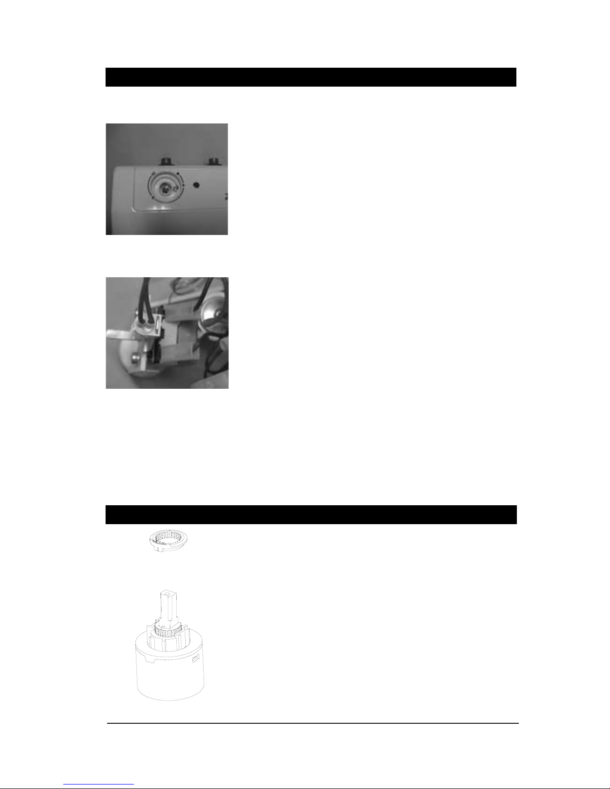
Removing the case
1. Remove temperature control knob by gripping it and pulling towards you.
2. Remove the single retaining screw located beneath the temperature control knob.
3. Remove the four case screws two at top, two at bottom.
4. The case can now be lifted off carefully.
Replacing the case
Reverse of the above procedure.
Replacing a thermostat
1. Remove the front cover.
2. Disconnect the two electrical terminals from the thermostat. These are
spade connectors and can be easily pulled off.
3. Remove the two screws attaching the thermostat to the plastic upright.
4. Pull the capillary out of the thermostat pocket located on the element
assembly.
5. Take the new thermostat (Z90421) and uncoil about half of the capillary tube.
6. Push the new capillary into the pocket ensuring that:
a) if it is an over sink model, the cutout bulb goes in first then the
thermostat bulb behind it.
b) if it is a under sink model, then the reverse is applicable.
Attach the thermostat to the plastic upright.
Reconnect the two electrical terminals. It does not matter which way around
the connections occur.
Ensure the remaining capillary coil is out of the way of any live terminals.
Ensure the plastic upright is located securely in the position provided.
Refit the cover assembly.
Adjustment of a tap temperature limiter on Solo and Hero vented taps
should be made only by a Zenith Service Provider or a qualified
technician.
1. Remove tap handle assembly to expose the mixer cartridge.
2. Lift and rotate the serrated top ring "X" from the mixer cartridge "Y".
Rotating the ring left or right will regulate the water temperature.
Rotating the ring clockwise will increase the water temperature.
Rotating the ring anticlockwise will decrease water temperature.
The tap normally operates with the ring in the central position.
3. Reassemble the tap handle assembly to its original condition.
4. Test the temperature of the water outlet to check acceptability.
# Tap Temperature Adjustment
# Service Procedures
Mixer Cartridge “Y”
Top Ring “X”
Zenithenithudor - Installation & Operating Instructions - 81333 - May 2003 Page 7
Knob removed to show screw
Thermostat spade connectors
Zenith Tudor - Installation & Operating Instructions - 81333 - July - 2004 Page 7
Page 8

Zenith Tudor - Installation & Operating Instructions - 81438 - June 2004 Page 8 of 8
Head Office
Parex Appliances
103 Central Park Dr
Henderson Auckland
Email: info@parex.co.nz
Website:www.parex.co.nz
Telephone (09) 836 6566
Facsimile (09) 836 6033
The Zenith appliance you have chosen is precision-built from the finest materials
available and should give many years of trouble free service.
Certain warranties may be implied by law into your contract with Zenith. The
warranty provided below is additional to these implied warranties and nothing
set out below shall limit your statutory rights or rights at law.
Parex Appliances warrants that, should any part fail within 12 calendar
months of installation, that part will be repaired or replaced free of charge by
Parex Appliances or its Distributor or Service Provider, except as set out below,
provided the appliance is installed and used strictly in accordance with the
instructions supplied, and that failure is not due to accident, misuse, abuse,
unsuitable water conditions, or to any alteration, modification or repair by any party
not expressly nominated by Parex Appliances.
No costs are payable by the customer other than any mileage or travelling-time
charges incurred by a Zenith Service Provider or the cost of removal, cartage and
re-installation of any component of the appliance if it needs to be returned for
repair its Distributor.
This warranty does not cover damage resulting from non-operation of the
appliance or consequential damage to any other goods, furnishings or property.
No warranty applies to the life of any filtration cartridge installed with the
appliance as cartridge life may vary according to water quality and the rate of
water consumption.
Parex Appliances does not exclude, restrict or modify any liability that cannot be
excluded, restricted or modified or which cannot, except to a limited extent, be
excluded, restricted or modified as between the owner or user and Parex Appliances
under the laws applicable.
Furthermore, this warranty does not displace any statutory warranty, but, to the
extent to which Parex Appliances is entitled to do so, the liability of Parex Appliances
under any statutory warranty will be limited at Parex Appliances option to the
replacement of the appliance or supply of equivalent appliance, the payment of the
cost of replacing the appliance or acquiring an equivalent appliance, or the payment
of the cost of having the appliance repaired or the repair of the appliance.
 Loading...