

Page 1
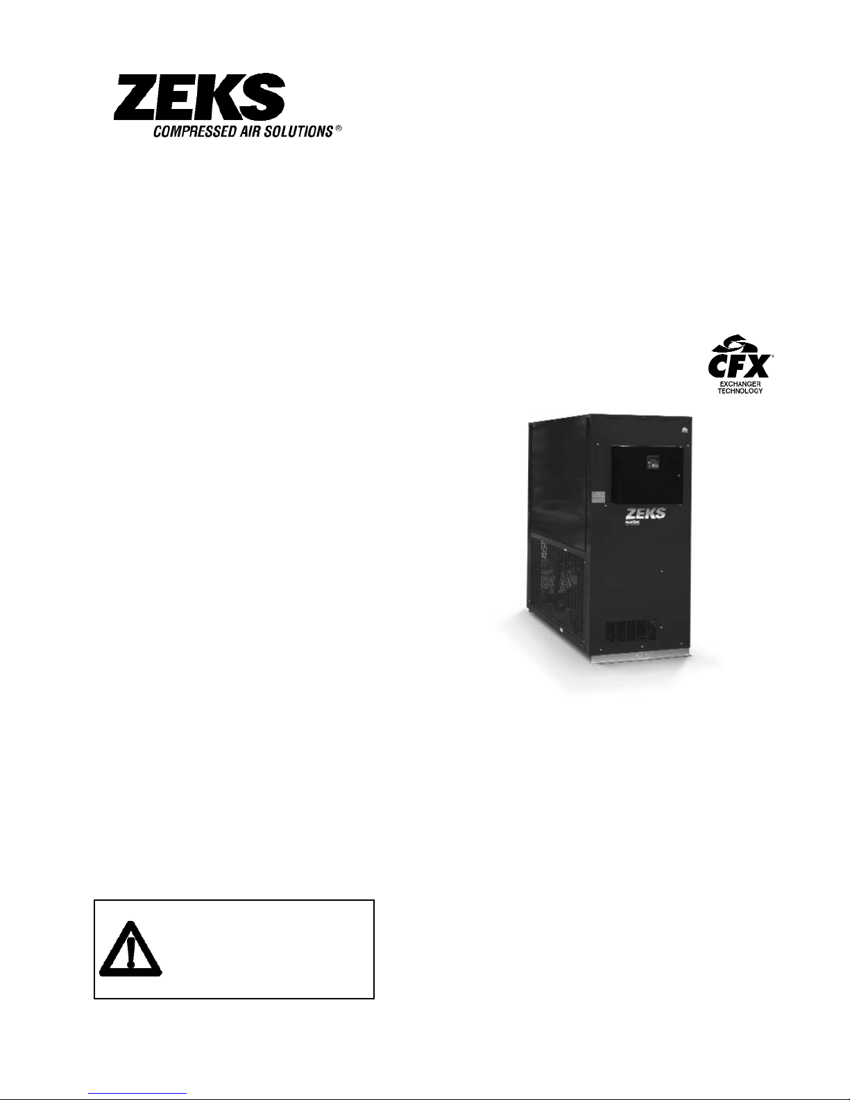
TECHNICAL MANUAL
HeatSink
True-Cycling Refrigerated
Compressed Air Dryers
HSF Models
1000-1600 SCFM
ZEKS Compressed Air Solutions
1302 Goshen Parkway
West Chester, PA 19380
Phone: 610-692-9100
800-888-2323
Fax: 610-692-9192
Web: www.zeks.com
Form: TM 1000-1600HSF-DPC-0513
DPC
Patent No.: 6,186,223
NOTICE
Those operating the machine or performing
maintenance should read and understand the
decals positioned on the machine and
contents of this Technical Manual.
Ensure that this Technical Manual is not
removed permanently from the machine.
TM
Page 2

TABLE OF CONTENTS PAGE
1. INTRODUCTION 2
2. ABBREVIATED WARRANTY 2
3. REFRIGERATED DRYER NOMENCLATURE 3
4. RECEIVING AND INSPECTION 4
5. SAFETY AND OPERATION PRECAUTIONS 5
6. PRINCIPLES OF OPERATION 6
7. INSTALLATION AND INITIAL STAR T-UP 15
8. SCHEDULED MAINTENANCE 18
9. TECHNICIAN MODE 20
10. TROUBLESHOOTING 23
11. WIRING DIAGRAMS 25
12. GENERAL ARRANGEMENT 31
13. PARTS IDENTIFICATION 32
14. ENGINEERING SPECIFICATIONS 33
TECHNICAL MANUAL
HeatSink
True-Cycling Refrigerated Compressed Air Dryers
HSF Models
1000-1600 SCFM
Patent No.: 6,186,223
TM
ZEKS Compressed Air Solutions
1302 Goshen Parkway
West Chester, PA 19380
Phone: 610-692-9100
800-888-2323
Fax: 610-692-9192
Web: www.zeks.com
Page 3

2. ABBREVIATED W
ARRANTY
ZEKS refrigerated dryers are warranted to be free from defects in material and workmanship for a period of 12 months from the original date of shipment from the factory. To
allow the warranty to be in effect for 12 months from the date of equipment start-up, the
Warranty Registration Card must be completed and returned to ZEKS. Alternately, the
Warranty Registration Card may be completed online at www.zeks.com. The total
warranty period cannot exceed 18 months from the original date of shipment from the
factory.
Equipment must be installed and operated in accordance with ZEKS’ recommendations.
ZEKS liability is limited to repair of, refund of purchase price paid for, or replacement in
kind at ZEKS’ sole option, during the warranty time period stated above. IN NO EVENT
SHALL ZEKS BE LIABLE OR RESPONSIBLE FOR INCIDENTAL OR CONSEQUENTIAL
DAMAGES, even if the possibility of such incidental or consequential damages has been
made known to ZEKS Compressed Air Solutions. In addition, the usual maintenance and
replacement type products are not covered by this warranty.
REFRIGERANT COMPRESSORS
A prorated warranty for the replacement of the refrigerant compressor will be extended to
a maximum of 60 months (5 years) from the original date of shipment from the factory.
Following the standard warranty terms, the available prorated compressor warranty is as
stated below. This prorated warranty applies to replacement compressor only and does
not cover any labor expenses.
Prorated coverage of price from date of shipment from the factory:
19 to 24 months 70%
25 to 36 months 50%
37 to 48 months 30%
49 to 60 months 10%
2
1. INTRODUCTION
The ZEKS HeatSink refrigerated air dryer removes moisture, oil vapor, and other contami-
nants from compressed air. These contaminants are detrimental to pneumatically
operated appliances, controls, instruments, machinery and tools. This is accomplished by
cooling the air with a refrigeration unit to a temperature at which moisture in the air is
condensed and separated from the airstream. The temperature the air is cooled to,
normally between 36 and 40°F, is known as dew point. This dryer can be easily installed
into various pneumatic systems in which dry air is required or desired. Please refer to
Principles of Operation for complete operating details.
Page 4
3
HEAT EXCHANGERS
Dryers that utilize CFX heat exchanger technology (HSF, HSG, NCE & NCG) are covered
for a total of 10 years from the original date of shipment from the factory. Following the
standard warranty terms the available warranty is as stated below. The exchanger
warranty applies to the replacement exchanger only and does not cover any labor
expenses.
Prorated coverage of prices from date of shipment from the factory:
18 to 48 months 100%
49 to 60 months 70%
61 to 72 months 50%
73 to 84 months 30%
85 to 96 months 20%
97 to 120 months 10%
Freight and labor coverage varies internationally. Refer to Distributor Warranty Guidelines
for limitations and detailed explanation of warranty coverage.
The warranties expressed above are in lieu of and exclusive of all other warranties. There
are no other warranties, expressed or implied, except as stated herein. There are no implied warranties of merchantability or fitness for a particular purpose, which are specifically
disclaimed.
3. REFRIGERA
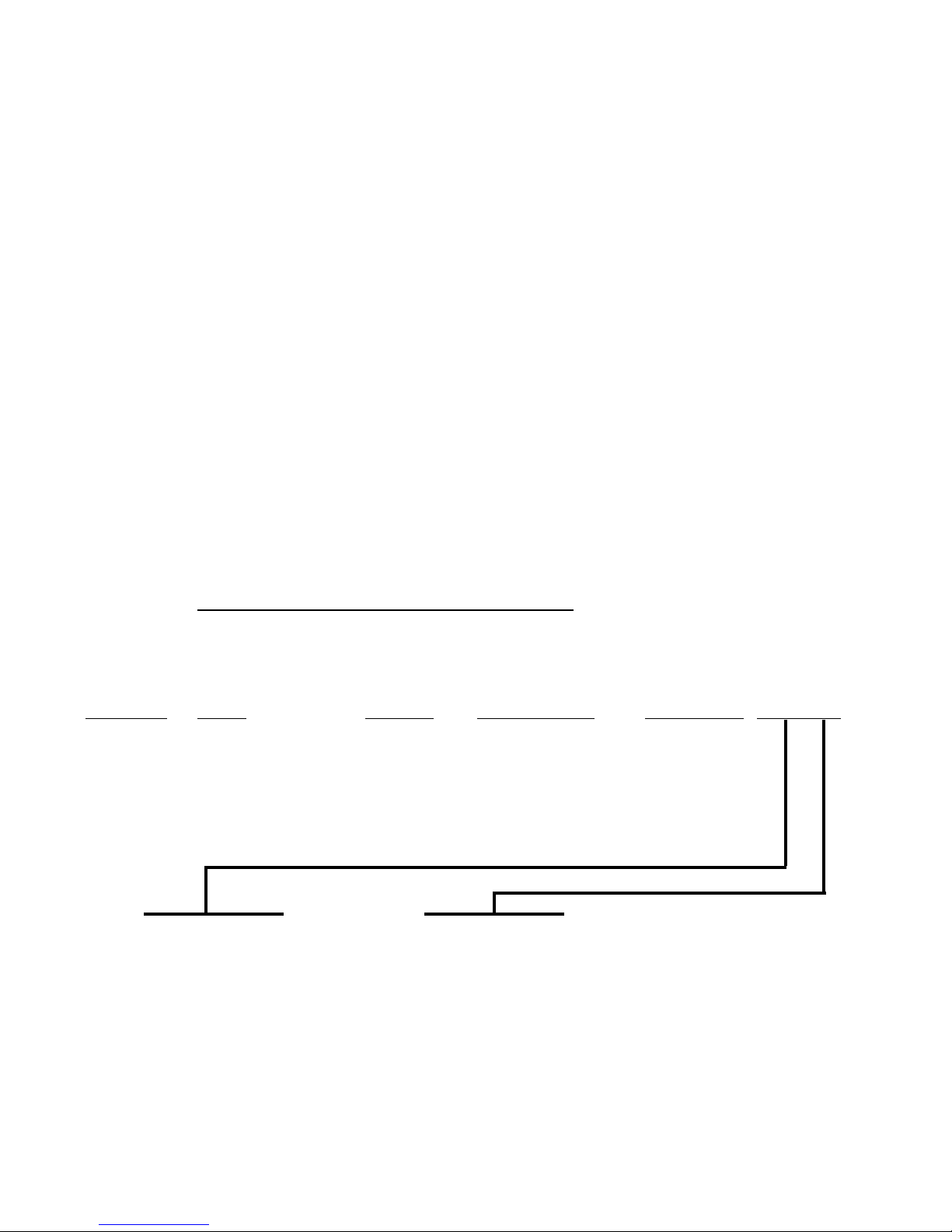
TED DRYER NOMENCLATURE
NOMINAL
FLOW DESIGN CONDENSER
SCFM
TYPE SERIES TYPE POWER OPTIONS
1000, 1200 HS= HeatSink F A=Air Cooled 4=460-3-60
1600 W=Water Cooled 5=230-3-60
6=575-3-60
O = STANDARD O = STANDARD
H = NEMA 4 Z = SPECIAL
W = WEATHERPROOF 8 = DPC-8
F = AMBIENTAIR FILTER
Page 5

4. RECEIVING
AND INSPECTION
4.1 INSPECTION
Upon receiving your ZEKS air dryer, please inspect the unit closely. If rough handling
has been detected, please note it on your delivery receipt, especially if the dryer will
not be immediately uncrated. Obtaining the delivery person’s signed agreement to
any noted damages will facilitate any insurance claims
4.2 UNPACKING AND HANDLING
Under no circumstances should any person attempt to lift heavy
objects without proper lifting equipment (i.e., crane, hoist, slings or
fork truck). Lifting any unit without proper lifting equipment, can
cause serious injury.
All dryer packages have been mounted on a base which provides for forklifting
between the two base channels to facilitate handling during shipment. Forks should
extend all the way through forklift channels to reduce unnecessary forces to the dryer
during moving. Slings can be used to lift the crates, but spreader bars must be used
to prevent the slings from exerting a force against the sides of the crates.
4
WARNING
Page 6
5
5. SAFETY AND OPERATION PRECAUTIONS
Because an air dryer is pressurized and contains rotating parts, the same precautions
should be observed as with any piece of machinery of this type where carelessness in
operation or maintenance could be hazardous to personnel. In addition to obvious safety
rules that should be followed with this type of machinery, safety precautions as listed
below must be observed:
OSHA
Heading Descriptions
1. Only qualified personnel shall be permitted to adjust,
perform maintenance or repair this air dryer.
2. Read all instructions completely before operating unit.
3. Pull main electrical disconnect switch and disconnect
any separate control lines, if used, before attempting to
work or perform maintenance on the unit.
4. Do not attempt to service any part while machine is in
an operational mode.
5. Do not attempt to remove any parts without first relieving
the entire air system of pressure.
6. Do not attempt to remove any part of the refrigeration
system without removing and containing refrigerant in
accordance with the EPA and local regulations.
7. Do not operate the dryer at pressures in excess of its
rating.
8. Do not operate the dryer without guards, shields and
screen in place.
9. Inspect unit daily to observe and correct any unsafe
operating conditions.
The user of any air dryer manufactured by ZEKS Compressed Air Solutions, is hereby
warned that failure to follow the above Safety and Operation Precautions may result in
personal injury or equipment damage. However, ZEKS Compressed Air Solutions
does not state as fact, nor does it mean to imply, that the preceding list of Safety and
Operating Precautions is all inclusive, and further, that the observance of this list will
prevent all personal injury or equipment damage.
“Warning” is used to indicate a
hazardous situation which has
some probability of death or
severe injury. Warning should
not be considered for property
damage accidents unless
personal injury risk is present.
“Notice” is used to indicate a
statement of company policy
as the message relates directly
or indirectly to the safety of
personnel or protection of
property. Notice should not be
associated directly with a
hazard or hazardous situation
and must not be used in place
of “Danger,” “Warning,” or
“Caution.”
CAUTION
“Caution” is used to indicate a
hazardous situation which may
result in minor or moderate
injury.
NOTICE
NOTICE
WARNING
Page 7
6
6. PRINCIPLES OF OPERATION
6.1 INTRODUCTION
ZEKS HEATSINK™ dryers remove moisture from compressed air by cooling the air
temperature to between 36° and 40°F (2 and 4°C). This causes vapors to condense
into liquid droplets which can then be easily removed from the air. The major
systems of the dryer which contribute to its operation are the Air System, the Moisture
Removal System, the Refrigeration System, the Thermal Mass Circulating System
and the Controls. The following paragraphs describe each of the systems in greater
detail.
6.2 AIR SYSTEM
The air system consists of the dryer components which are in contact with the
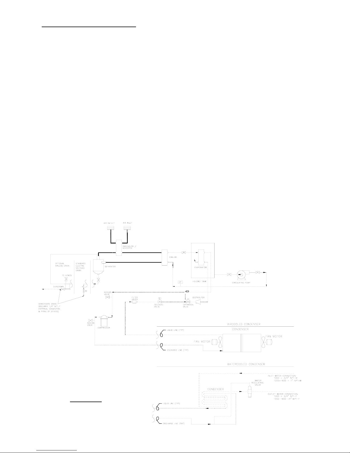
compressed air. Referring to Figure 1 and following the bold “
AIR FLOW,” hot saturated
air from the compressor enters the precooler/reheater where the air temperature is
reduced prior to entering the chiller by the cool air exiting the air/moisture separator.
This precooling allows for the use of a smaller refrigeration system. The air then
goes into the chiller section where it is further cooled to the desired dew point by a
thermal mass fluid. The temperature of the thermal mass fluid is maintained by the
refrigeration circuit and controls. The air continues to the separator where moisture is
removed, thereby, allowing the cool, dry air to return to the precooler/reheater to be
heated by the incoming moist hot air. The air exiting the “reheater” portion of the
dryer should be approximately 15°- 20°F lower than the inlet air temperature based
on standard conditions at full rated flow.
FIGURE 1
FLOW DIAGRAM
DRAWING 500161
Page 8

7
6.3 MOISTURE REMOVAL SYSTEM
Liquid droplets are removed from the air stream in the separator. As the air and
liquid mixture passes through the separator it spins, slows down and then changes
direction. This causes the condensate to fall out of the air stream and collect in the
bottom of the separator. The collected liquid is removed from the separator by a
solenoid valve. The solenoid valve is controlled by the microprocessor controller as
described in Section 6. For adjustment please note the following:
• To obtain the optimum time values for operation of the solenoid drain valve, set
the off-time to three minutes and the on-time ten seconds via the controller.
• After running the unit under full rated flow for approximately 30 minutes, verify that
when the solenoid drain opens, all of the accumulated liquid is discharged and then
a small burst of air.
• If a small amount of liquid and a large amount of air is discharged, decrease the ontime setting or increase the off-time setting. If there is all liquid and no air has been
discharged, increase the on-time setting or decrease the off-time setting.
• The on/off time settings will vary according to seasonal operating conditions. During
the summer when more moisture is present in the air system a shorter on-time,
increasing the valve opening frequency, is required. A longer valve off-time may be
used during the winter months when moisture levels are lower.
6.4 REFRIGERATION SYSTEM
The Refrigeration System consists of all the components which handle refrigerant.
This is a hermetically sealed closed-loop system. Referring to Figure 1 and following
the phantom “
REFRIGERANT FLOW,” refrigerant is shown leaving the evaporator section
where, in the process of removing heat, it is changed from a low pressure liquid into
a low pressure gas. This gas enters the suction side of the compressor where it is
compressed into a high pressure gas. The high pressure gas is cooled in the air
cooled or water cooled condenser section until it becomes a high pressure liquid. It
then goes through a permanent filter dryer that ensures the refrigeration system is
free of contaminants. A thermostatic expansion valve meters the refrigerant for
introduction into the evaporator. The refrigerant pressure is reduced upon entering
the evaporator where as it evaporates, heat is removed from the thermal mass fluid.
A solenoid valve in the liquid line eliminates the possibility of flooded starts.
6.5 THERMAL MASS CIRCULATING SYSTEM
The thermal mass fluid in a ZEKS HEATSINK™ dryer is continuously circulated in a
closed pump loop system. Referring to Figure 1 and following the dashed “
THERMAL
MASS FLUID” line, the heat is removed from the fluid in the evaporator by the refrigera-
tion system. The thermal mass reservoir is sized to minimize refrigeration cycles
during reduced air load periods. The thermal mass fluid is pulled from the bottom of
the reservoir and pumped through the chiller, removing heat from the air and returned
to the evaporator. The pump utilized on ZEKS’ HEATSINK™ dryer is a maintenancefree, quiet cartridge circulator pump similar to those used in residential water
systems. While the refrigeration system cycles on and off based on loading
conditions, the circulating pump runs continuously to maintain flow through the chiller
at all times.
Page 9

6.6 CONTROLS
ZEKS’ 1000-1600HSF Refrigerated Compressed Air Dryers are equipped with the
Digital Performance Controller (DPC™). This advanced microprocessor-based
controller has been engineered by ZEKS exclusively for use with ZEKS’ Compressed
Air Dryers.
The DPC™ cycles the refrigeration system based on the dryer's Chiller Temperature.
A temperature sensor samples the thermal mass temperature as it enters the chiller
exchanger. The Chiller Temperature Set point is a user adjustable set point that is
used to set the Refrigeration Compressor Off temperature. Once the Chiller
Temperature has fallen below the Chiller Temperature Set point, the refrigeration
compressor will de-energize. The Operating Temperature Differential is factory set at
4°F above the Chiller Temperature Set point. Therefore, if a user adjusts the Chiller
Temperature at 36°F, the Refrigeration Compressor On temperature will be 40°F.
In addition to the operation of the HeatSink™ dryers as described above, the DPC™
permits monitoring of dryer parameters and enunciation of alarm conditions.
The list below summarize the features the DPC™:
• 2 X 16 Character Backlit LCD Display - Easy-to-read display provides continuous
indication of dryer default parameter. Standard backlight permits viewing of critical
information in low light environments.
• Electronic Drain with On/Off Time Adjustment: Included with DPC™-equipped
HeatSink™ and NonCycle dryers is a solenoid drain valve. Control of the open and
close time of the valve is set via the DPC™ Controller.
• Remote Start / Stop: DPC™-equipped dryers offer a unique remote start / stop
feature. This feature allows the dryer to be operated via a remote user-supplied
switch.
• Remote Alarm Contact: DPC™-equipped dryers include a remote alarm contact to
provide indication of any of the dryers alarms described later in this manual.
Contact rated for 2A / 120V max.
The DPC™ Controller features three levels of access. The default level CUSTOMER
MODE permits adjustment of dryer parameters to address seasonal variations for
drain timing and pressure dew point temperature. Aprotected TECHNICIAN MODE
permits access to and manipulation of additional parameters to address the initial
machine set up. Apassword protected FACTORY MODE is also included for use with
ZEKS Service Personnel for troubleshooting the dryer.
8
Page 10

The DPC™ controller includes a digital readout for monitoring the discharge pressure
of the refrigerant gas exiting the compressor. This reading will vary dependent upon
condenser type as indicated below:
• For air-cooled applications, condensing fans are cycled on and off by the DPC
based on the refrigerant discharge pressure. Primary fan(s) are cycled on at 235
psig and off at 195 psig. Should the discharge pressure continue to climb above
265 psig, the secondary condensing fans will cycle on. As discharge pressure is
reduced below 210 psig, the secondary fan(s) will cycle off. On 1000 and
1200HSF models, two condensing fans are utilized. The 1600HSF has three
condenser fans. For the 1600HSF, the center fan is the primary controlled fan
the outside fans are the secondary controlled fans.
• Water cooled condensers utilize a water regulating valve (Note Figure 2). The
water regulating valve comes pre-adjusted from the factory at 250 psig discharge
pressure. To compensate for water temperature variation, it may be necessary to
adjust the water regulating valve to maintain a 250 psig discharge pressure.
Adjustment can be done by rotating the adjusting screw counterclockwise for an
increase in discharge pressure. For conditions where low water temperature
and/or high water pressure are expected it is advisable to install a water pressure
regulator ahead of the condenser.
ADJUSTMENT SCREW
FIGURE 2
WATER REGULATING VALVE
Drawing 600562
9
Page 11
10
6.6.1 BASIC USER INTERFACE
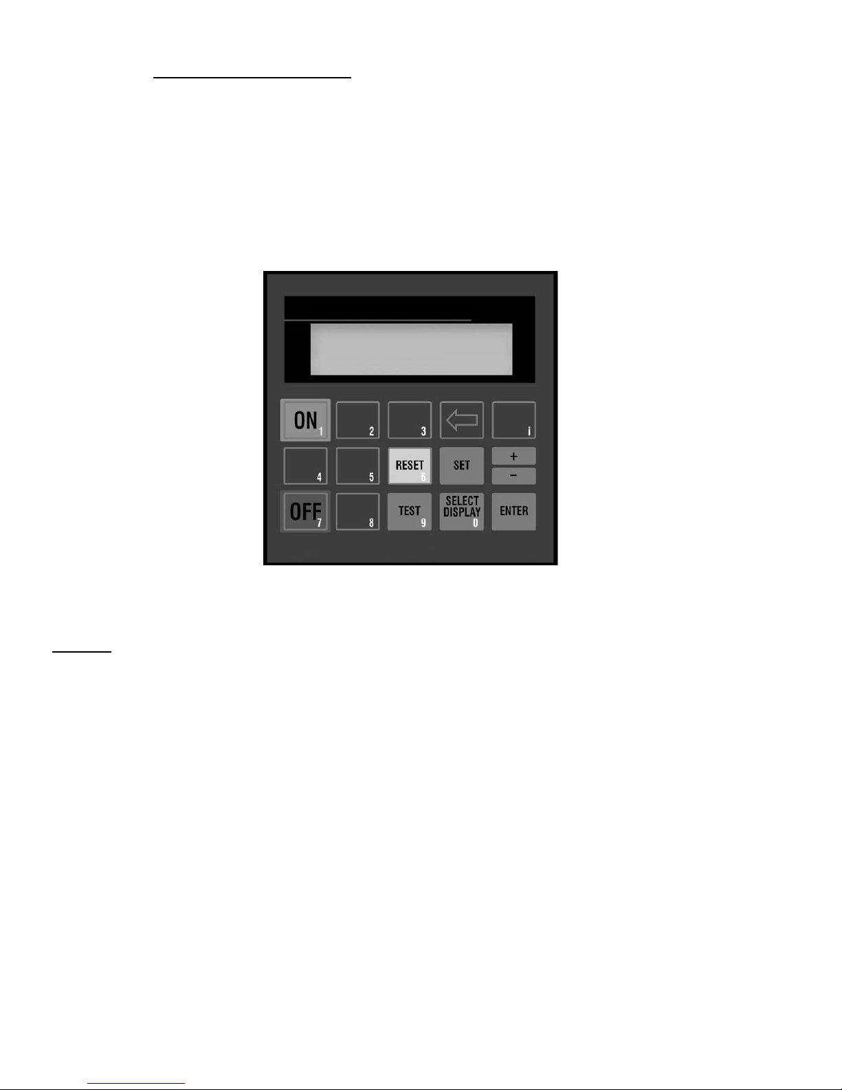
The DPC™ display provides the user with the operating parameters and their
corresponding values. The following illustration summarizes the keypad functions.
BUTTONS
• ON
Places the dryer "On Line"; Energizes glycol pump on
HeatSink™ dryers. For HeatSink™ models, the
compressor will operate based on temperature;
• OFF
Places the dryer "Off Line"; Stops all automatic functions,
including circulating pump operation on HeatSink™ dryers.
• SELECT DISPLAY
Allows the user to cycle through the available displays.
The last display selected will remain displayed as the
default display.
• + / Allows user to increase set point values. Set point values
cycle through a fixed range. Also allows entering negative
numbers in FACTORY MODE.
• TEST
Allows user to manually activate the drain solenoid valve.
• RESET
Pressing once clears the local alarm indication and deenergizes the remote alarm contact. Should the alarm
condition persist, the alarm will return after the alarm
inhibit time has expired.
• SET
Permits the adjustment of parameters in TECHNICAN
and FACTORY MODES. In CUSTOMER MODE, allows
user to back through displays,
• ENTER
Used to accept changed parameters and set point
values.
• i
Restricted Level access for factory use only. Not used
for basic dryer functions. Not to be used by customer or
service technician.
CHLLR TEMP: 37
Page 12

11
6.6.2 DISPLAY PARAMETERS
The DPC™ Controller is capable of displaying a number of system parameters.
The following summarizes the parameters that can be accessed by the user from
the DPC™ Controller:
• Chiller Temperature (CHLLR TEMP): For HeatSink Dryers, the Chiller
Temperature is the temperature, in degrees Fahrenheit, of the thermal mass fluid.
• Compressor Status (CMPRSSR): Displays whether the refrigeration compressor
is “ON” or “OFF”.
• Discharge Pressure (P disch): Displays the discharge pressure of the refrigeration
system.
• Suction Temperature (T suction): Displays the suction temperature, in deg. F, of
the refrigeration system. This value is useful in determining superheat of the
refrigerant.
• Suction Pressure (P suction): Displays the suction pressure, in psig, of the refrig-
eration system.
• Inlet Air Pressure and Temperature (P AIR IN / TAIR IN): Displays the tempera-
ture, in °F and pressure, in psig, of the inlet compressed air. (DPC™-Plus Only)
• Outlet Air Pressure and Temperature (P AIR OUT / TAIR OUT): Displays the
temperature, in °F and pressure, in psig, of the outlet compressed air. (DPC™Plus Only)
• Drain Interval (DRN INT): Displays the length of time, in minutes, between
operation of the solenoid drain.
• Drain On (DRN ON): Displays the length of time, in seconds, that the solenoid
drain is open.
• Percent Savings (% SVGS): Displays the length of time the compressor has been
operating versus the length of time the dryer has been on.
• Cumulative Dryer Hours (CUM DRYER HR): Displays the length of time, in hours,
that the dryer has been operational.
• Cumulative Compressor Operating Hours (CUM CMP HR): Displays the length of
time, in hours, that the refrigeration compressor has been energized.
Depressing the SELECT DISPLAY button repeatedly scrolls through the above
non-adjustable displays. The Customer Set Points appear at the end of the list
and may be adjusted by the end user to match seasonal refrigeration and drain
operation. These settings are as follows:
• Chiller Temperature (CHLLR TEMP)
• Drain Interval (DRN INT)
• Drain On (DRN ON)
Page 13
12
SELECT
DISPLAY
Pressing SELECT DISPLAY will increment the display
through the available display parameters.
Depress “ + / -“ as required to change the DRN INT time
to 5 minutes.
Pressing “ENTER“ saves the set point.
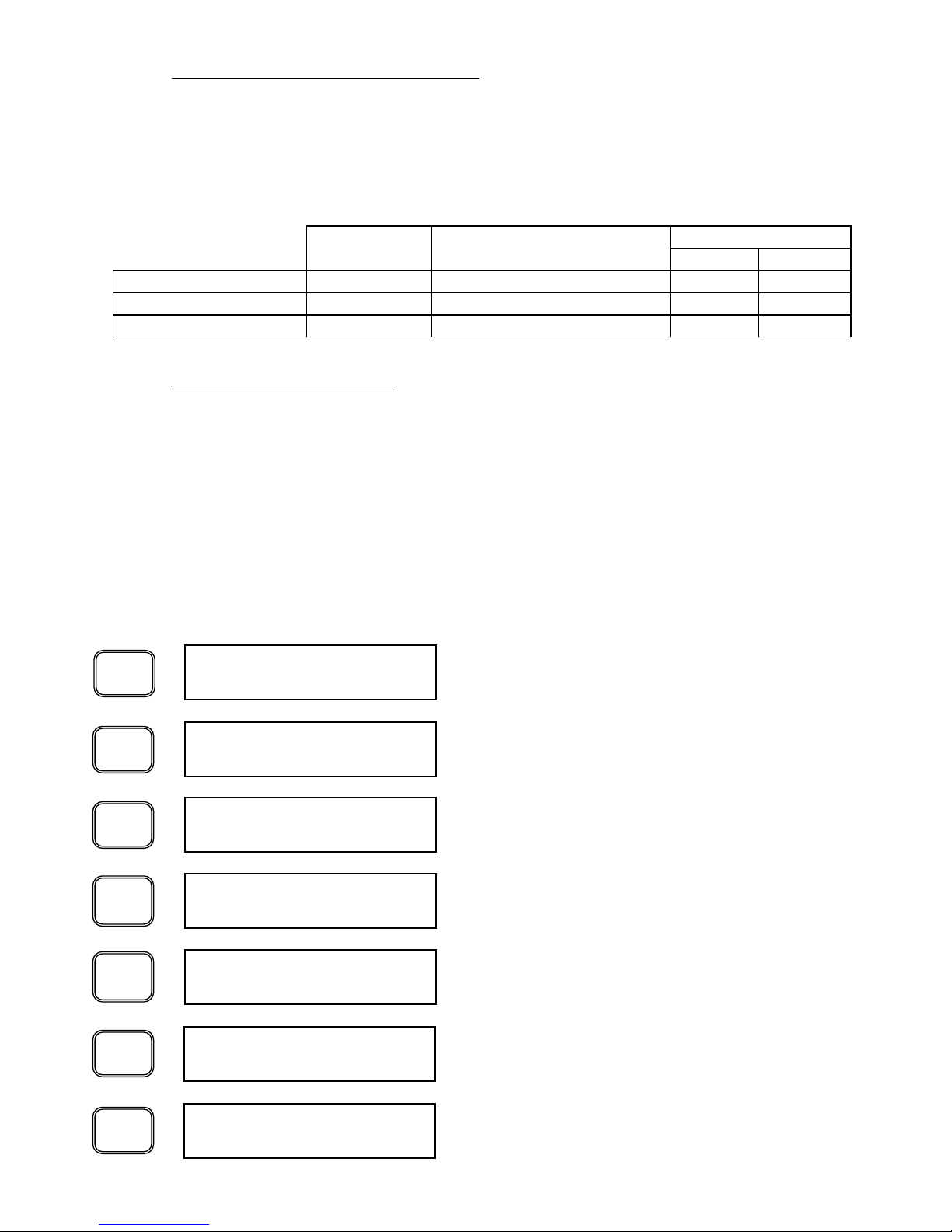
6.6.4 ADJUSTING SET POINTS
Accessing and manipulating each of the set points in the CUSTOMER MODE is
accomplished as follows. The parameter is selected using the SELECT DISPLAY
button. After scrolling through the displays, the “Cust Set Points” screen is
displayed. The parameters after this screen may be adjusted by the user. Once
the desired parameter is displayed, depressing the “+/-” button changes the set
point. Once the new set point is displayed, depressing ENTER saves the set point.
Exiting the Customer Set Point routine is accomplished by depressing the SELECT
DISPLAY button until the END CUST SET PTS screen is displayed. The following
example illustrates the keystrokes required to change the Drain Closed Time from
the default value of 3 Minutes to 5 Minutes:
6.6.3 DRYER SET
POINTS AND ALARMS
The DPC™ Controller has several user adjustable set points that are displayed at
the end of the display parameter list. These set points allow the user to configure
the dryer to operate according to site conditions. The controller is shipped from the
factory with each parameter having its own default value. The following chart
summarizes the parameters that may be adjusted by the user:
Display Parameter
SETPOINT Description Range HeatSink NonCycle
Drain Interval Time DRN INT 3, 5, 10, 15, 20, 30, 60 min 3 MIN 3 MIN
Drain On Time DRN ON 3, 5, 7, 10, 12, 15 , 20, 30 sec. 10 SEC 10 SEC
Chiller Off Temperature CHLLR TEMP 32°F - 50°F; 1 °F increments 34°F INACTIVE
Factory Setpoint
ENTER
DRN INT: 5 min
SELECT
DISPLAY
Press SELECT DISPLAY as necessary to display the End
Customer Set points Screen.
End Cust Set Pts
DRN INT: 5 min
+
-
CHLLR TEMP: 36
SELECT
DISPLAY
Continue pressing SELECT DISPLAY until the Customer
Set point screen is displayed. The parameters that follow
are the User Adjustable Parameters for the controller.
Cust Set Points
SELECT
DISPLAY
Press SELECT DISPLAY until “DRN INT” is displayed.
DRN INT: 3 min
SELECT
DISPLAY
Press SELECT DISPLAY as necessary to return the DPC
to the desired display parameter.
CHLLR TEMP: 36
Page 14
13
6.6.5 ALARMS AND THEIR FUNCTIONS
There are several alarms detected by the DPC™ to alert the user of an out of
tolerance condition. Once each alarm is detected, a description of the alarm will
appear in the screen and the remote alarm contact will close. Note that during the
alarm condition, the SELECT DISPLAY button may be depressed to scroll through
the available parameters. After approximately 30 seconds, the alarm screen will
reappear, provided the alarm condition persists.
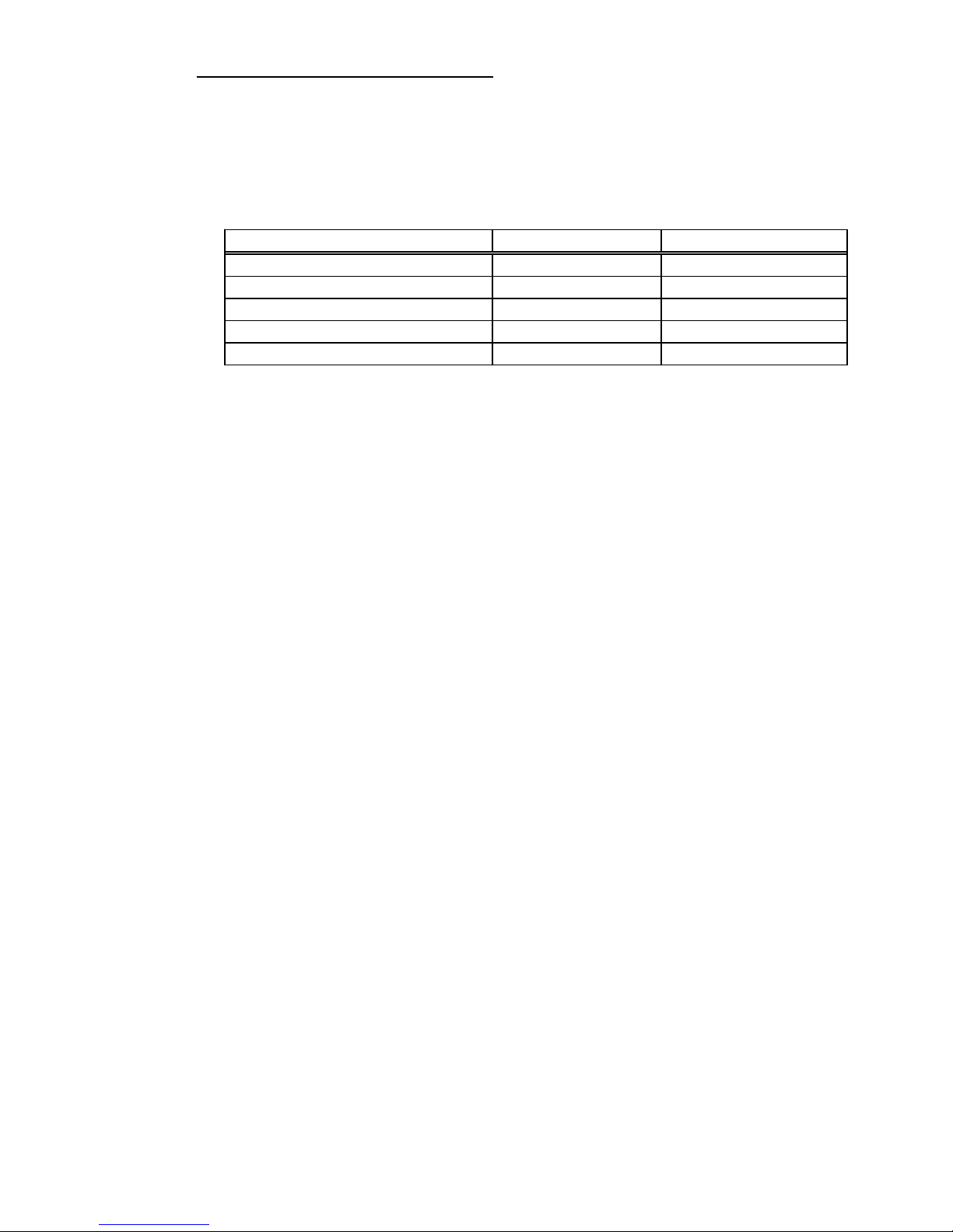
The alarm names and description of each are described in detail below. Note that
some alarms will enunciate only after a prescribed alarm delay. Refer to the
TECHNICIAN MODE section of this manual for factory default alarm delay periods
.
HIGH TEMPERATURE ALARM (HITEMP ALARM)
When the thermal mass (glycol) temperature in a HeatSink™ dryer (separator
temperature for NonCycle dryers) reaches the factory alarm set point, after an
alarm delay, the alarm will be activated. This alarm condition may not necessarily
damage the dryer when subjected to long-term exposure. It may, however, have a
significant impact on downstream processes and thus should be investigated upon
detection. Note that this alarm will not shut down the dryer. This alarm will activate
the remote alarm contact and reset automatically once the alarm condition is
rectified.
LOW TEMPERATURE SAFETY ALARM (LOWTEMP ALARM)
If the dryer chiller temperature falls to or below the factory set point and remains at
or below this set point for the factory delay time, the alarm routine will activate.
This alarm condition may cause damage to the dryer when subjected to continuous
or long-term exposure. Note that this alarm will shut down the dryer after a
response time delay. This alarm will activate the remote alarm contact and reset
automatically once the alarm condition is rectified.
HIGH PRESSURE CUTOUT ALARM (HPCO ALARM)
If the discharge pressure of the refrigerant is determined to be above the set point,
the alarm routine will activate. This alarm condition may cause damage to the
dryer when subjected to continuous or long-term exposure. Note that this alarm will
shut down the dryer after a response time delay. The operator must depress the
RESET button in order to clear the alarm and restart the refrigeration system
.
LOW PRESSURE CUTOUT ALARM (LO PRESS CO)
If the suction pressure of the refrigerant is determined to be below the set point of
the LPCO alarm, the DPC alarm routine will activate. This alarm condition may
cause damage to the dryer when subjected to continuous or long-term exposure.
Note that once cleared, the compressor will restart automatically. However, if two
successive low-pressure conditions are determined, this alarm will shut down the
dryer after a response time delay and will display the alarm condition. The operator
must depress the RESET button in order to reinstate the compressor.
Alarm Display Alarm Set Point
HIGH PRESSU RE CUTOUT HI PRESS CO See Table 1
LOW PRESSU RE CUTOUT LO PRESS CO See Ta ble 1
HIGH TEMPERATURE ALARM HI T EMP ALRM 55 °F
LOW TEMPERATURE ALARM LOTEMP ALRM 30 °F
HIGH DRAIN LEVEL ALARM DRAIN LVL ALARM N/A
Page 15

HIGH DRAIN LEVEL ALARM - OPTIONAL (DRAIN LVLALARM)
On dryers equipped with the optional High Drain Level Alarm, should condensate
rise to a predetermined level in the separator, a liquid level switch will signal the
DPC and the High Drain Level Alarm will enunciate. In addition to indicating the
alarm on the LCD and closing the remote alarm contact, the High Drain Level Alarm
will open the solenoid drain in an attempt to correct the problem. The condition will
not shut off the dryer. Once the source of the problem has been addressed, the
alarm will automatically reset.
6.6.6 ST
ART
MODES
ZEKS dryers are capable of starting in one of three start modes. Note that to
protect the refrigeration compressor from repeated rapid starts, the DPC™ is
equipped with an an anti-short cycle (ASC) delay. The ASC delay will countdown
from the factory set point (see TECHNICIAN MODE). Only after the ASC delay
has timed out will the refrigeration system operate. Below are brief descriptions of
these various start modes.
6.6.6.1 Manual Mode
ZEKS dryers are shipped from the factory in the Manual Mode. After power is
supplied to the dryer, the user will be presented with the ASC delay, followed by the
“PRESS ON BUTTON” display. After the ASC delay has timed out, the dryer will
only start once the ON button is depressed. In this configuration, to restart the
dryer, the user must manually depress the ON button on the dryer’s control panel.
6.6.6.2 Auto Restart Mode
After power is applied to the dryer, and once an anti-short cycle delay has timed
out, the dryer will start automatically. In addition, this mode of operation allows
manual control of the dryer via the ON & OFF pushbuttons. This is useful for
applications where automatic restarting of the dryer is desired after a power failure
has occurred.
6.6.6.3 Remote Automatic Mode
This mode of operation allows the user to control the dryer remotely and requires
the installation of a customer-supplied contact. With power applied to the dryer
and once the anti-short cycle delay has timed out, the dryer will start automatically
once the switch is closed. In addition, this mode of operation still permits manual
control of the dryer via the ON & OFF pushbuttons. Note that the signal to the
Remote Alarm Contact must be 24V.
TABLE - 1
14
Parameter R-404A R-407C
Fan 1 ON 275 psig 235 psig
Fan 1 OFF 195 psig 195 psig
Fan 2 ON 335 psig 265 psig
Fan 2 OFF 235 psig 210 psig
HPCO (Air-Cooled) 450 psig 400 psig
HPCO (Water-Cooled) 320 psig 320 psig
LPCO 20 psig 20 psig
Page 16
Failure to comply to the above instructions may result in equipment malfunction
and will void warranty.
Always use a backup wrench when making any threaded connection to the dryer.
Failure to use a backup wrench may result in damaged tubing and components
internal to the cabinet.
7.2 PIPING AND VALVES
Install piping, fittings and accessories as required for specific site conditions and
requirements. Figure 3 indicates a typical piping arrangement for a refrigerated dryer,
including dryer and filter bypasses. This figure can be used as a guide for valve and
accessory placement in the system.
ZEKS 1000 through 1600 HSF models come factory installed with a drain isolation
valve (D). The isolation valve permits maintenance of the automatic drain without
isolating air flow to the dryer. To operate dryer, all valves shown in Figure 3 are to be
closed except valves (B), (C) and (D). Valve (A) is used for bypass purposes and
valve (E) is for test and manual drain purposes.
7. INSTALLATION AND INITIAL START-UP
7.1 LOCATION AND MOUNTING
The dryer should not be located in an area where ambient temperature is likely
to exceed 113°F (45°C) or be less than 50°F (10°C). The dryer must be located in
an area that provides sufficient clearance from walls and other adjoining equipment
to allow easy access for servicing and maintenance requirements. A minimum of
30 inches is required to allow free flow of air to the condenser inlet and clearance for
servicing the dryer.
On installations with a relatively steady flow rate, the dryer is normally connected after
the air receiver. If loads fluctuate widely, the dryer should be positioned ahead of the
receiver and sufficient storage capacity downstream is necessary to prevent
excessive air flow through the dryer.
When installed after any compressor that causes significant vibration or air pulsation,
such as reciprocating compressors, proper vibration isolation and pulsation
dampening devices should be added to protect the dryer.
NOTICE
Dryers equipped with the optional SDD200H drain are shipped with a foam
material inside the drain housing to protect the internal components of the drain
during shipment of the dryer. The foam material must be removed and the
supplied 3/4” plug installed in the designated port prior to start-up.
NOTICE
NOTICE
15
Page 17
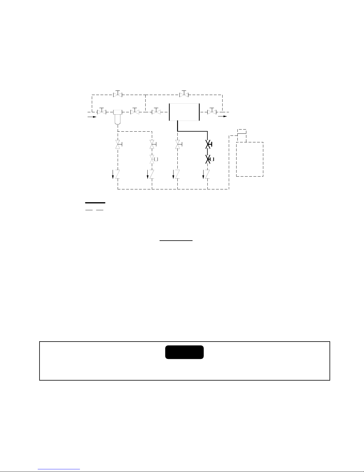
FIGURE 3
TYPICAL PIPING ARRANGEMENT
AIR
DRYER
OIL
SEPARATOR
DRAIN
VALVE
CHECK
VALVE
CHECK
VALVE
CHECK
VALVE
DRAIN
VALVE
CHECK
VALVE
PREFILTER
B
A
C
AIR OUT
AIR IN
DE
UNIT AS DELIVERED
OPTIONAL ACCESSORY ITEMS
NOTE:
DRAIN TUBE MUST NOT RISE OR BE CONNECTED TO
EXCESSIVELY LONG PIPE WHICH MAY CREATE BACK PRESSURE
A CONNECTION TO OPEN FLOOR DRAIN IS REQUIRED
7.4 ELECTRICAL CONNECTION
Equipment is available in various electrical configurations. All customer connections
can be made at the terminal connections located in the customer electrical connection
box on the rear of the dryer. (Refer to General Arrangement and appropriate Wiring
Diagrams.)
A suitable fused disconnect switch or circuit breaker, in accordance with national and
local code requirements, is recommended for all ZEKS equipment. Refer to the
Engineering Specifications section for voltage requirements and load.
7.4.1 ZEKS dryers can be configured for three variations of start modes: Manual Mode,
Automatic Mode and Remote Mode. The instructions below describe the methods
to configure the dryer for a particular Start Mode.
A) Manual Mode (Factory Default) - No modification required to operate dryer in
Manual Mode. Once power is applied, dryer can be started or stopped by
depressing the local ON / OFF pushbuttons located on the front panel.
Never wire directly or connect any additional wires to the compressor
junction box. This will cause severe system malfunction.
CAUTION
16
7.3 FILTRATION
To protect the air dryer from gross contamination associated with compressor oil and
debris and ensure maximum dryer performance, a prefilter is recommended.
Prefilters and afterfilters sized to your drying application can be provided by ZEKS and
are available factory installed. Call your local distributor to select the filter that best
suits your filtration requirements. In addition to air filtration, condensate discharge
oil/water separators are also available to address stringent EPA regulations.
Page 18
B) Auto Restart Mode - Auto Restart Mode permits the dryer to start after a brief
delay once power is applied to the dryer. In TECHNICIAN MODE, changing the
Auto Restart parameter from the default “N” to “Y” using the SET button enables
this mode of operation. Note that the dryer’s touch pad will still affect dryer
operation. Depressing the OFF button will de-energize the refrigeration
compressor and all other electrical components. After the OFF button has been
depressed, the user must depress the ON button to permit the dryer to operate.
C) Remote Mode - Remote Mode allows the dryer to be turned ON or OFF via a
remote switch supplied by the customer. This mode will work regardless of the
setting for Auto Restart. The dryer must be powered on for this feature to take
effect. To enable this feature:
• Install N.O. remote switch as indicated on the appropriate wiring diagram.
• Customer-supplied contact should be rated at 1A at 24V. To operate dryer,
close switch or contact and allow dryer to start after an initial delay. The
local On / OFF pushbuttons may also be used at any time after contact
closure.
17
7.5 INITIAL START-UP
For water cooled models, the water valve must be manually opened
to ensure that the condenser is full of water prior to start-up.
7.5.1 START- UP SEQUENCE
• Apply power to dryer. LCD Panel will illuminate. The Anti-Short Cycle delay will
commence counting down. Remaining time on the Crankcase heater will also
countdown.
After installation or a prolonged shutdown, start the dryer with no air load (no air flow).
This enables the dryer to reach its proper operating temperature in the shortest time
possible (typically within 30 minutes for HeatSink™ dryers).
NOTICE
NOTICE
Allow 8 hours of warm-up time for the crankcase heater prior to start up.
Crankcase heater is connected directly to the incoming power and is
energized at all times.
CAUTION
Page 19
18
8.0 SCHEDULED MAINTENANCE
8.1 INTRODUCTION
ZEKS HEATSINK™ refrigerated air dryers require little maintenance. These dryers
utilize hermetically sealed compressors which do not require any lubrication. Fan
motors require lubrication at both oil ports every six months. ZEKS recommends
component inspection and service at regular intervals to obtain maximum performance from your dryer.
8.2 REFRIGERANT CONDENSER
For standard dryers, regular inspection and cleaning of the condenser is
recommended. ZEKS dryers may be equipped with an optional ambient air filter
designed to protect the condenser from dirt and debris that can accumulate on the
condenser. For proper operation with this option, it is imperative that this filter be
inspected and cleaned on a regular basis. Annual replacement of the filter is
recommended. For applications where excessive dirt, dust or debris is encountered,
more frequent inspection and cleaning may be required.
• Start Dryer, using one of the following methods, depending on Start Mode setting:
Manual Mode - Press the ON pushbutton.
Auto Restart Mode - No additional action required
Remote Automatic Mode - Close the remote contact.
• For HeatSink™ dryers, the circulating pump will be energized and will run continuously. Provided the CHILLER TEMPERATURE is greater than the Compressor
Off Set point plus 4° F and the anti-short cycle delay and crankcase heater delay
have timed out, the refrigeration system will energize. As the system operates
and thermal mass temperature drops, the suction pressure will be lowered to
between 30 and 50 psig.
After the alarm delay, provided the Chiller Temperature is greater than the HIGH
TEMPERATURE ALARM set point, the dryer will go into HIGH TEMPERATURE
ALARM. The LCD panel will indicate the alarm and the refrigeration system will
continue to operate. Pressing the SELECT DISPLAY button will permit viewing of
the available dryer parameters during this alarm condition. Note that the alarm
condition screen will reappear after approximately 30 seconds until the alarm
condition is cleared.
The CHILLER TEMPERATURE will gradually drop as indicated on the display.
Once the temperature falls below the HIGH TEMPERATURE ALARM set point, the
alarm will reset and the LCD panel will return to its default display. After the refrigeration system shuts off, air flow may be slowly introduced to the dryer.
• Drain settings should be checked as described earlier in this manual.
If power is removed from the dryer for less than two hours, the crackcase heater delay
will be automatically bypassed. If, however, the power is removed from the dryer for
more than two hours, the full crankcase heater delay must be observed.
NOTICE
Page 20
19
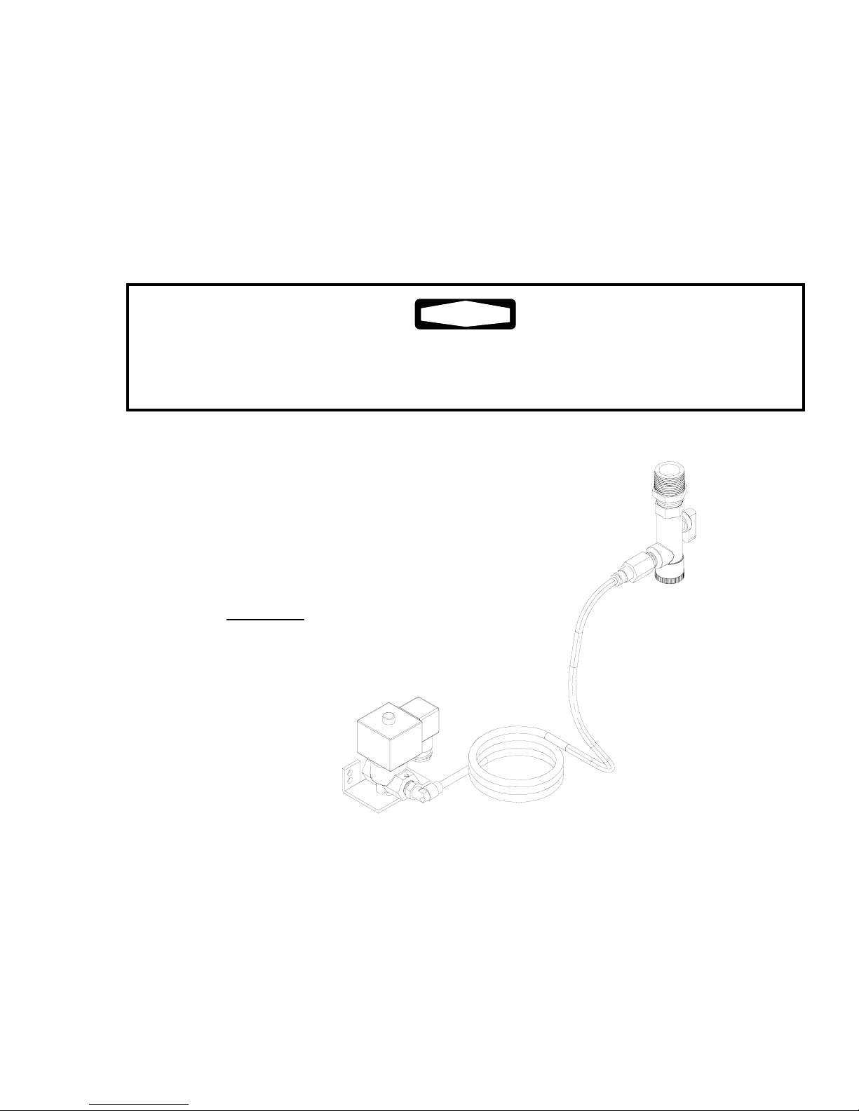
8.3 CONDENSATE DISCHARGE SYSTEM
On a minimum of a monthly basis, the operation of the automatic drain should be
checked. The drain should be removed and cleaned as well to ensure no debris
from the system is trapped inside the strainer. Figure 4 illustrates the drain
assembly. To clean the drain, turn the Isolation Valve to the off position. Be sure
the valve is depressurized. Carefully remove the Strainer End Cap and remove the
Strainer. Clean the Strainer and remove any debris that is evident in the valve.
Replace the Strainer and reinstall the Strainer End Cap. Carefully open the
isolation valve and inspect the Strainer End Cap for leaks. Tighten as required.
If your dryer is installed without a drain isolation valves (filter stop), failure to depressurize the dryer may result in serious injury. Do not remove the drain valve without
depressurizing the unit.
WARNING
NOTE: Orientation of drain and strainer may
be different than shown above.
FIGURE 4
DRAIN DETAIL
DRAWING 749830
Page 21
20
9.0 TECHNICIAN MODE
The DPC provides a protected TECHNICIAN MODE to manipulate several parameters not
accessible by the typical operator. This mode also permits viewing of the factory settings
to aid in troubleshooting of the dryer. Below is a list of parameters that can be accessed
and manipulated by the technician when in TECHNICIAN MODE:
TECHNICIAN MODE should only be entered by qualified service personnel. Altering the
set points in TECHNICIAN MODE will have a significant effect on the operation of the
dryer. Incorrect set points may damage dryer and cause potential serious injury.
Paramete r Display Set Point
SOLENOID DRAIN ENAB LE DRAIN ENABL E ON (o r OF F)
CRANKCASE HEA TER DELAY CCH DLY 8 (or 0,2,4,12 hours)
AUTO RESTART ENABLE AUTO RESTART N (or Y)
Paramete r Display Set Point
CONFIGURATION (# of sensors) CONFIG #: 1, 2, 4, 8
OPERATING MODE OP MODE: HS or NC
REFRIGERANT REFRIG: 22 or 404 or 407
CONDEN SER TYPE COND: AC OR WC
OPERATING TEMPERATURE DIFFERENTIAL T OP DIF F : 4
SHORT CY CLE DELAY SHT CYC DLY: 03
HIGH PRESSU RE CUTOUT HPCO: See Ta ble-1
HIGH PRESSU RE CUTOUT DELAY HPCO DLY: 10
LOW PRESSU RE CUTOUT LPCO: See Table-1
LOW PRESSU RE CUTOUT DELAY LPCO DLY: 10
HIGH TEMPERATURE ALARM HITEMP AL RM: 55
LOW TEMPERATURE ALARM LOWTEMP ALRM: 30
LOW TEMPERATU RE ALARM DELAY LOTEMP DLY : 2:00
FAN 1 ON PRESSURE FAN1 ON: See Table-1
FAN 1 OFF PRESSURE FAN1 OFF: See Table-1
FAN 2 ON PRESSURE FAN2 ON: See Table-1
FAN 2 OFF PRESSURE FAN2 OFF: See Table-1
ALARM LIST BEGIN ALARM LIST N/A
In TECHNICIAN MODE, the following parameters can be viewed but not changed:
9.1 ENTERING TECHNICIAN MODE
WARNING
Page 22
21
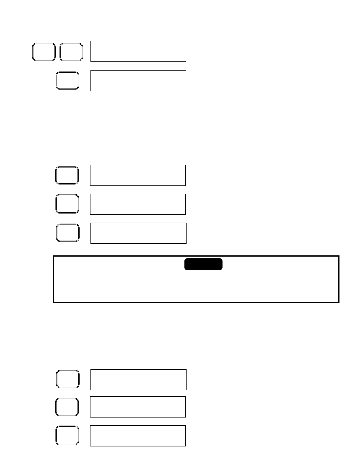
To enter the TECHNICIAN MODE, perform the following keystrokes:
Pressing the “2” and “3” buttons simultaneously enters
the TECHNICIAN MODE.
TECH SET MODE
SELECT
DISPLAY
Depressing SELECT DISPLAY scrolls through the
available parameters. The first three parameters viewed
are adjustable in TECHNICIAN MODE.
DRAIN ENABLE: ON
2
3
Depressing ENTER saves the selected set point.
Depressing the SELECT DISPLAY button advances to
the next adjustable parameter for the Crankcase Heater
Delay. This parameter must not be altered unless
instructed by ZEKS Service personnel.
DRAIN ENABLE: OFF
CCH DELAY: 8
SET
For parameters with “ON / “OFF” or “Y” / “N” choices, the
set point is changed using the SET button. Pressing the
SET button changes the Drain Enable from ON to OFF.
DRAIN ENABLE: OFF
ENTER
SELECT
DISPLAY
Depressing ENTER saves the selected set point.
AUTO RESTART: Y
SET
Depressing the SET button changes the AUTO RESTART
parameter from “N” to “Y”.
AUTO RESTART: Y
ENTER
Depressing the SELECT DISPLAY button advances to
the next adjustable parameter for the Auto Restart
feature.
AUTO RESTART: N
SELECT
DISPLAY
The DRAIN ENABLE parameter determines whether the DPC shall control an electronic
solenoid drain valve. Avalue of “ON” will permit the DPC to control the drain valve. A
value of “OFF” will disable this feature. This would be suitable for servicing the drain
valve or if an independent no air loss drain is to be used with the dryer. To change the
DRAIN ENABLE set point from the displayed set point, perform the following. Otherwise,
depress the SELECT DISPLAY button to advance to the next adjustable parameter:
The AUTO RESTART feature permits the dryer to operate once power is applied to the
dryer without requiring operator intervention. This would be desirable should the user
wish to have the dryer restart automatically after a power outage. Note that the dryer will
energize once the ASC or CCH delay times out. To change the AUTO RESTART set point
from “N” (NO) to “Y” (YES), perform the following. Otherwise, depress the SELECT
DISPLAY button to advance to the next display:
The Crankcase Heater Delay set point must not be altered unless directed by ZEKS
Service Personnel. Improperly altering the set point may result in damage to the dryer.
Contact ZEKS Compressed Air Solutions before altering the default set point.
NOTICE
Page 23
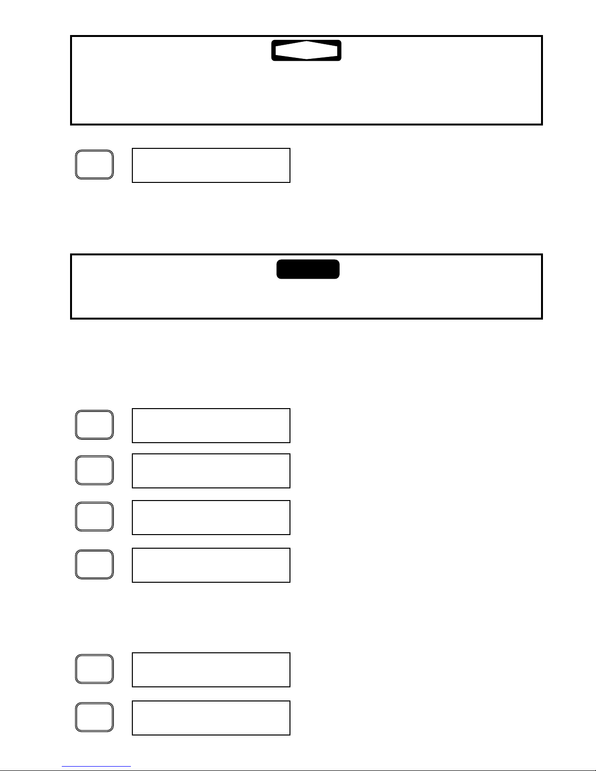
Depressing the SELECT DISPLAY button displays the
END TECH SET PTS display.
END TECH SET PTS
SELECT
DISPLAY
At the end of the list of parameters, depressing the
SELECT DISPLAY button displays the beginning of the
ALARM LIST.
BEGIN ALARM LIST
SELECT
DISPLAY
Depressing the SELECT DISPLAY button displays the
alarms that the dryer has experienced, with the most
recent alarm displayed first. The actual display will
depend on the most recent alarm detected by the DPC.
HPCO ALARM
SELECT
DISPLAY
The list of alarms can be scrolled by depressing the
SELECT DISPLAY button as needed. At the end of the
alarm list, the END ALARM LIST screen is displayed.
END ALARM LIST
SELECT
DISPLAY
Depressing the SELECT DISPLAY list displays the
ALARM LIST screen at the top of the ALARM LIST.
BEGIN ALARM LIST
SELECT
DISPLAY
The Alarm List will repeat as long as the SELECT DISPLAY button is depressed.
To EXIT the ALARM LIST, perform the following:
Depressing the BLANK button (located above the SET
button) returns the controller to the top of the TECHNICIAN MODE.
TECH SET MODE
Depressing the BLANK button again returns the controller
to the default display of the CUSTOMER MODE.
CHLLR TEMP: 37
Changing the AUTO RESTART feature to “Y” will permit the dryer to operate automatically once power is applied and after a brief delay. Proper warning signs should be
affixed to the dryer to alert users and service personnel that dryer may start without
warning. Failure to do so may result in serious injury.
The remaining non-adjustable parameters may be viewed by depressing the SELECT
DISPLAY button as required to arrive at the desired display. .
To exit the TECHNICIAN MODE at any time, depress the “BLANK” button located
above the SET button to return to the CUSTOMER MODE.
9.2 ALARM LIST
At the end of the list of non-adjustable parameters, the DPC™ displays a list of the
most recent 20 alarm conditions. This list can facilitate troubleshooting the dryer
NOTICE
22
WARNING
Page 24
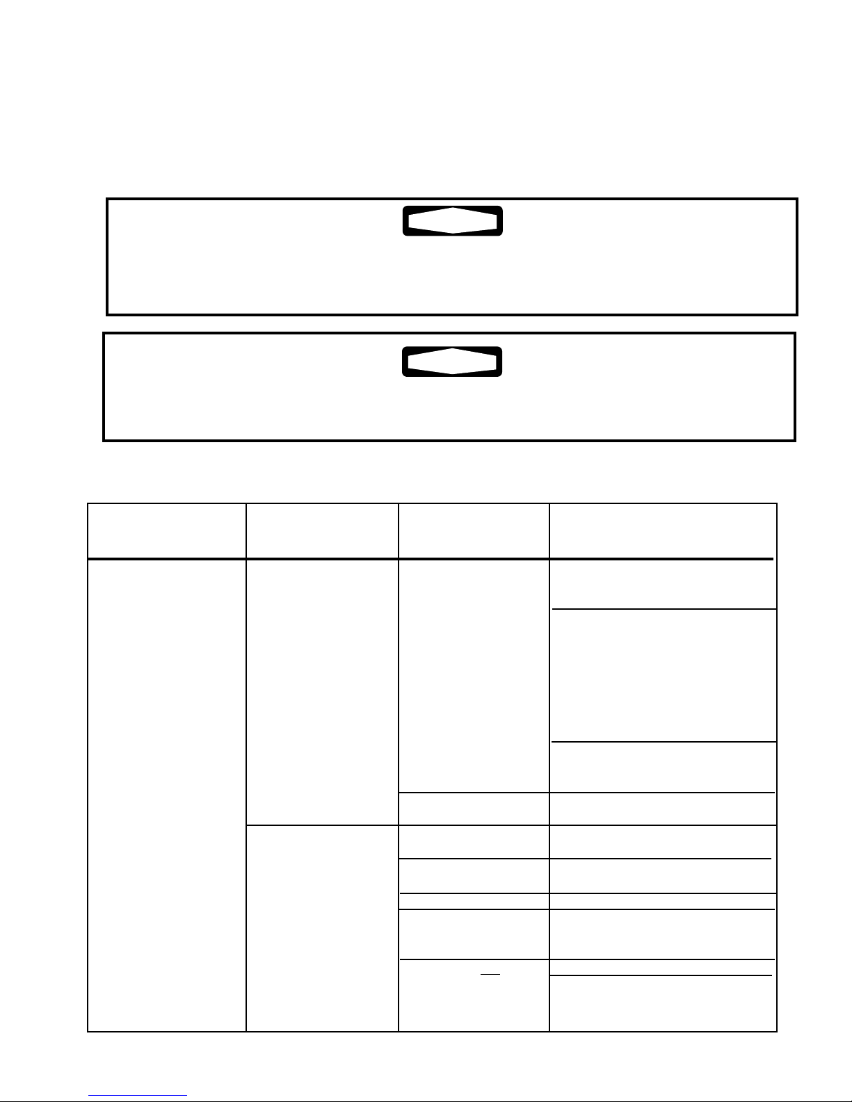
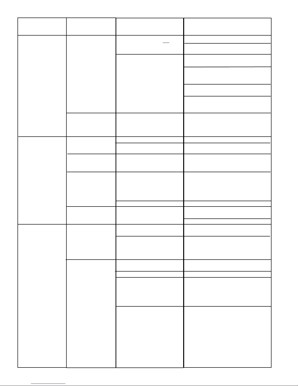
10.2 PROBLEM / ACTION GUIDE
PROBLEM
Moisture down stream
SYMPTOM(S)
Dryer is properly
cooling air stream
(Check Chiller Temp on
controller)
Inlet and outlet temperatures are the same.
POSSIBLE
CAUSE
Drain failure or timer
adjustment is required
Excessive flow
Dryer by-pass valve
not closed
No power to the dryer
High suction pressure
Refrigerant leak
Compressor not
running and fan is
running
CORRECTIVE ACTION
Depress “TEST” button - if drain
valve operates then adjust timing
(See Section 6.3)
Depress “TEST” button - if DRAIN
TEST is displayed but valve does
not open, ensure wiring connections are secure and power is being
applied to the solenoid coil. If valve
continues not to open, clean as
described in Maintenance Section
of this manual.
Depress “TEST” button - if display
does not indicate DRAIN TEST,
contact distributor.
Check inlet and outlet pressures
and system design capacity.
Correct cause of excessive flow.
Close by-pass valve
Check power supply and
fuses/circuit breakers
Check and clean ambient air filter.
Check suction pressure gauge if
reading is 0 psig, turn dryer off and
contact your distributor
Check and clean ambient air filter.
Check ambient temperature and
reduce below 113°F
An air dryer always operates under pressure. Any maintenance procedure that involves
disassembly of pipe fittings, valves or any other components requires the dryer be
isolated from the compressed air stream and fully depressurized.
Prior to working on the unit, make sure that all circuit breakers or disconnected switches
are tagged “Out of Service.”
10. TROUBLESHOOTING
10.1 INTRODUCTION
ZEKS HEATSINK™ dryers are designed for reliable, trouble-free operation. In the
event of any dryer malfunction, the guide below has been developed to facilitate
problem identification and corrective actions.
23
WARNING
WARNING
Page 25
24
PROBLEM
Moisture down
stream
Apparent controller
display malfunction
High pressure drop
across dryer
SYMPTOM(S)
Inlet and outlet
temperatures are the
same.
Compressor and fan
are running,
exchanger temp high,
pump not running
Display Blank
Unrealistic temperature displayed
Erratic or inaccurate
temperature readings
Unrealistic pressure
displayed
Outlet pressure
substantially lower
than inlet pressure
System operating
temperature is above
32°F
Outlet pressure
substantially lower
than inlet pressure
System operating
temperature is below
32°F
POSSIBLE CAUSE
Compressor and fan not
running.
Compressor and fan not
running. Controller indicates
compressor is ON.
Defective Pump
Blown Fuse
Board Failure
Probe loose,off connection or
defective probe
Probe not completely in
thermal well
Defective probe
Transducer loose, off connection or defective transducer
Inlet and outlet valves not
completely open
Inlet and outlet filters blocked
up
Compressor relay / contactor
stuck.
DPC relay bad
Probe not completely in
thermal well
Problem persists
CORRECTIVE ACTION
Check Chiller Temperature
Check MAIN CONTROL fuse.
Compressor relay may be bad, replace
relay
Check for loose wire connections at
contactor or loss of power at control
board
Defective control board - replace as
necessary
Contact your local distributor for further
assistance.
Contact your local distributor for further
assistance.
Check Fuses
Contact your local distributor for further
assistance.
Inspect probe cable and terminal
connection
Replace probe
Inspect probe and check readings
against independent source (eg.
temperature analyzer/pyrometer/ice
bath) both in temperature well and to
ambient
Replace probe
Inspect transducer cable and terminal
connection
Replace transducer
Open valves
Change filter elements
Replace relay / contactor.
Replace relay
Inspect probe and check readings
against independent source (eg.
temperature analyzer/pyrometer/ice
bath) both in exchanger well and to
ambient
Turn dryer off and consult your local
distributor for further assistance
Page 26
25
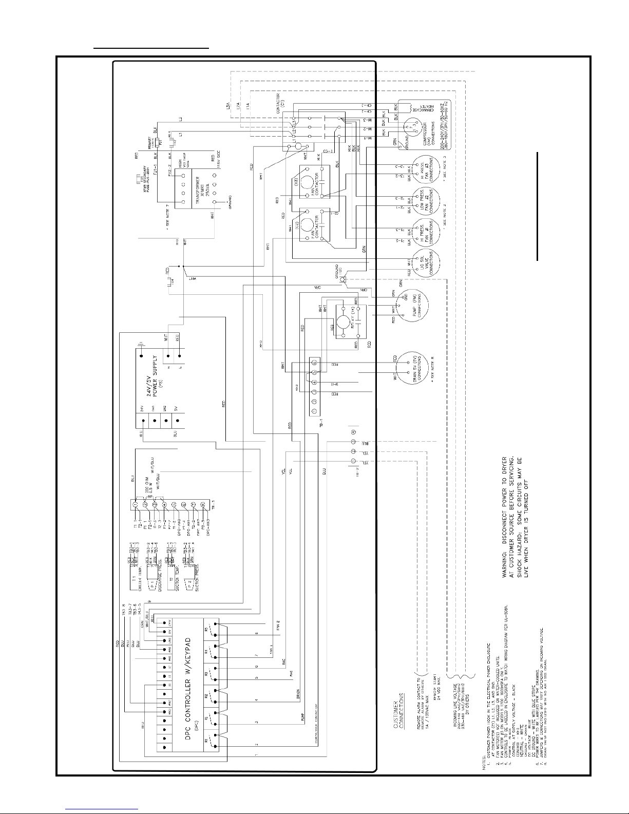
11. WIRING DIAGRAMS
WIRING DIAGRAM
1000-1600HSFA&W with DPC™460V/3/60HZ
1000-1200HSFA&W with DPC™230V/3/60HZ
TM500162V
Page 27
26
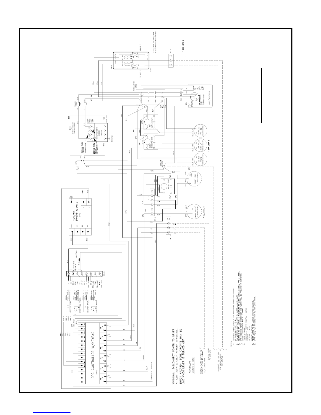
WIRING DIAGRAM
1000HSFA&W,1200HSFW with DPC™
575V/3/60HZ
TM500510G
Page 28
27
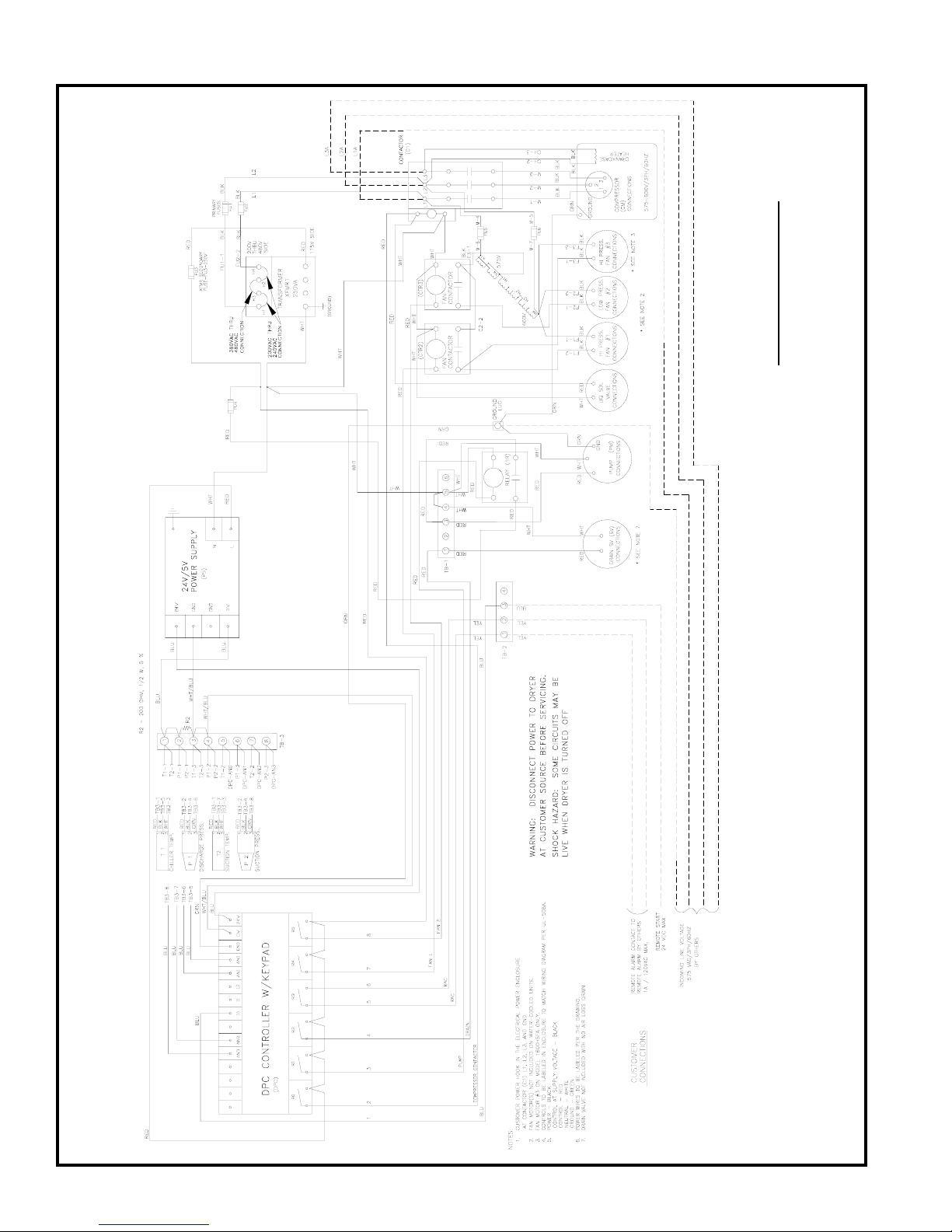
WIRING DIAGRAM
1200HSFA,1600HSFA&W with DPC™
575V/3/60HZ
TM500549G
Page 29
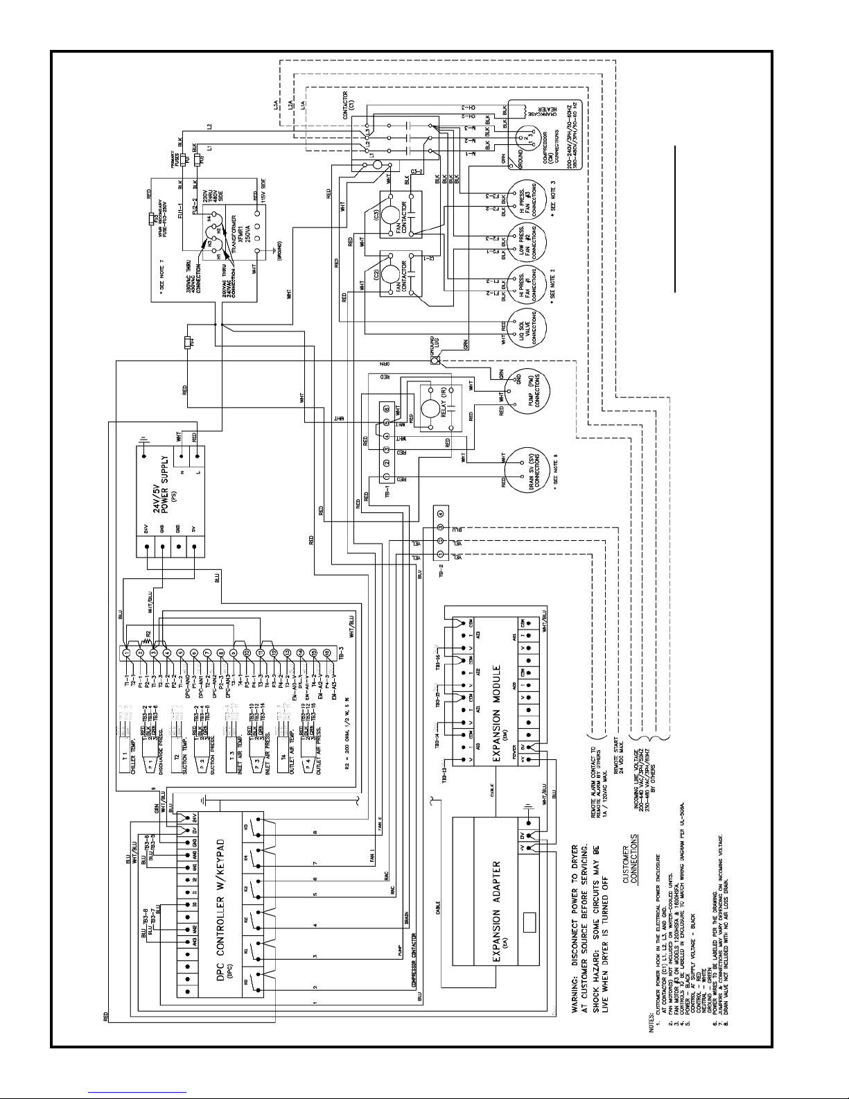
28
WIRING DIAGRAM
1000-1600HSFA&W with DPC™-PLUS
208, 230, 460V/3/60HZ
200, 220, 380, 400, 415, 440V/3/50HZ
TM500163Q
Page 30
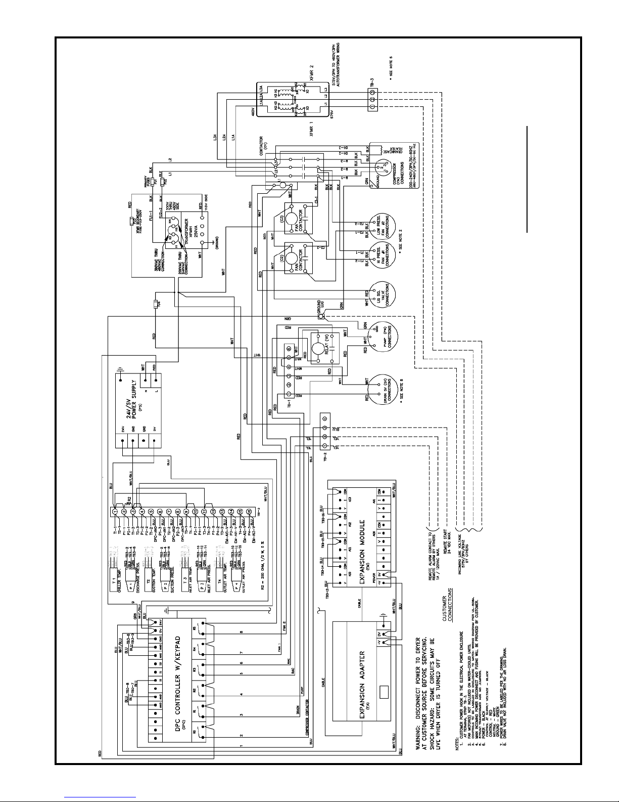
29
WIRING DIAGRAM
1000HSFA&W, 1200HSFA&W with DPC™-PLUS
575V/3/60HZ
TM500607B
Page 31
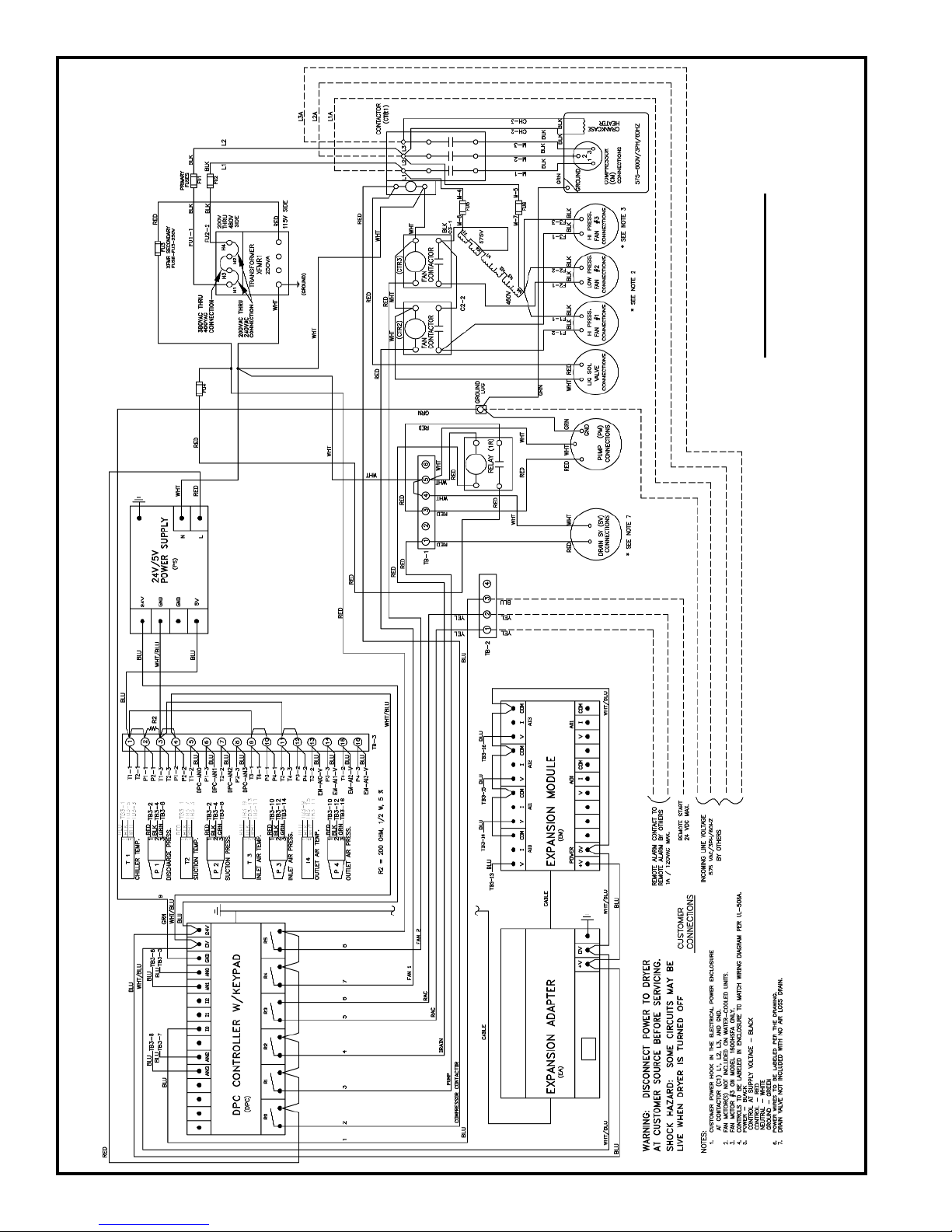
30
WIRING DIAGRAM
1200HSFA, 1600HSFA&W with DPC™-PLUS
575V/3/60HZ
with Transformed 460V Fans
TM500520F
Page 32
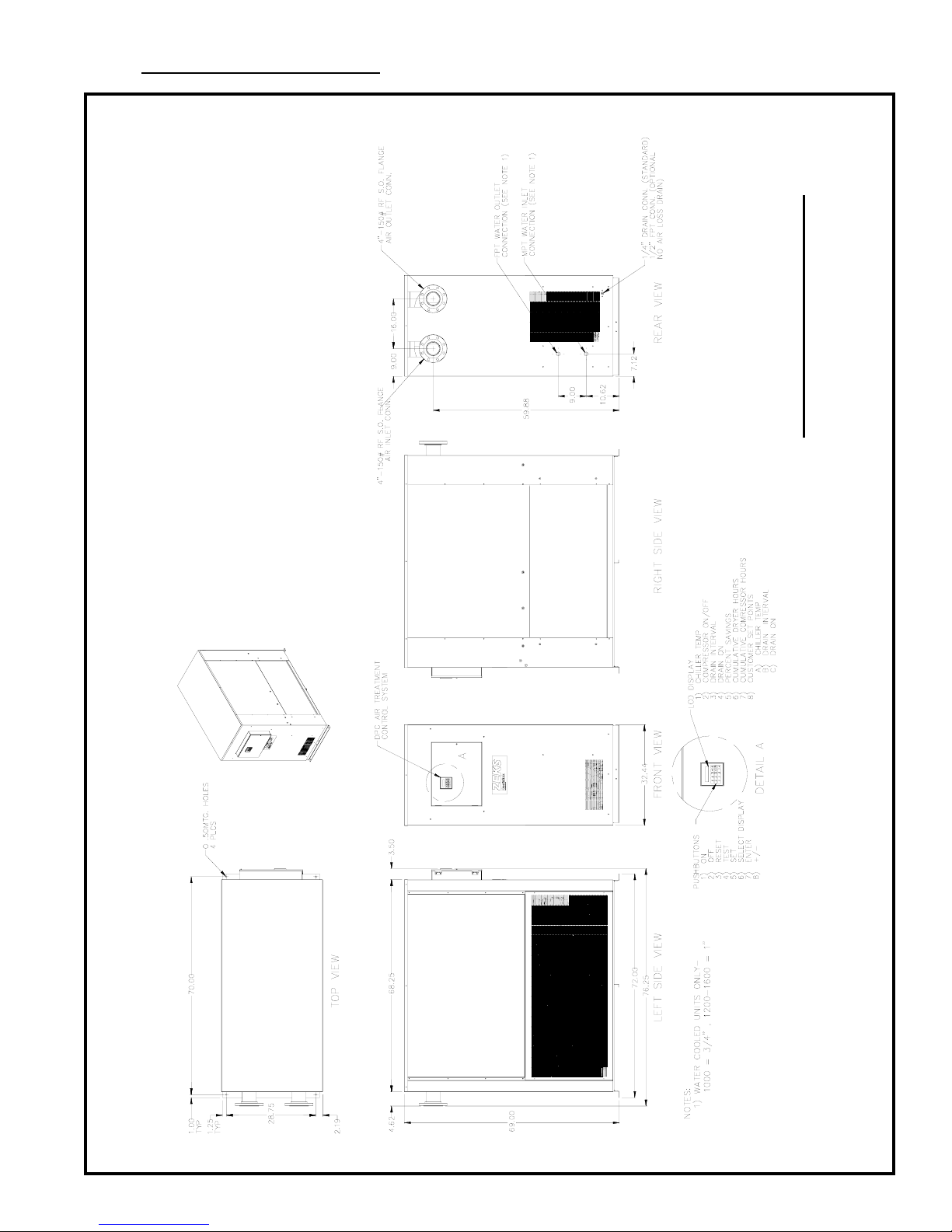
12. GENERALARRANGEMENT
GENERAL ARRANGEMENT
1000-1600HSF
TM500387G
31
Page 33
13. SPARE PARTS
32
1000HSFA400 1200HSFA400 1600HSFA400 1000HSFW400 1200HSFW400 1600HSFW400
Air-Cooled Air-Cooled Air-Cooled Water-Cooled Water-Cooled Water-Cooled
460/3/60 460/3/60 460/3/60 460/3/60 460/3/60 460/3/60
1 Compressor 684300 682248 682346 682578 682245 682248
2 Condenser 698478 684309 684323 682403 698202 698202
3 Fan Motor 698152 698152 684325 - - -
4 Fan Blade 698156 698156 684324 - - -
5 Pump - Glycol 683724 683724 683724 683724 683724 683724
6 Filter Dryer 600386 600388 600388 600388 600387 600388
7 Expansion Valve 684304 684304 684304 681600 681600 600401
8 Water Regulating Valve - - - 600563 698204 698204
9 Contactor - Single Pole, 25A 699621 699621 699621 - - -
10 Contactor - Three Pole, 25A 697290 697290 697290 697290 697290 697290
11 Control Transformer 699640 699640 699640 699640 699640 699640
12 Fuse, 2A, 1/4” 682646 682646 682646 682646 682646 682646
13 Fuse, 3A, 13/32” 698770 698770 698770 698770 698770 698770
14 Fuse, .75A, 13/32” 682651 682651 682651 682651 682651 682651
15 Power Supply Fuse 683976 683976 683976 683976 683976 683976
16 Digital Controller DPC 800087 800087 800087 800087 800087 800087
17 Power Supply 683956SP 683956SP 683956SP 683956SP 683956SP 683956SP
18 Temperature Probe 682955 682955 682955 682955 682955 682955
19 Pressure Transducer, Discharge, 0-500 PSI 682943 682943 682943 682943 682943 682943
20 Pressure Transducer, Inlet/Outlet Air & Suction, 0-300 PSI 682942 682942 682942 682942 682942 682942
21 Transducer Cable, refrig. Discharge & Suction - 5 ft. 682945 682945 682945 682945 682945 682945
22 Transducer Cable, Inlet & Outlet Air - 10 ft. (DPC-8 only) 682946 682946 682946 682946 682946 682946
23 Digital Controller Battery 683975 683975 683975 683975 683975 683975
24 Condensate Drain 682657SP 682657SP 682657SP 682657SP 682657SP 682657SP
25 Crankcase Heater 684605 684595 684595 682245 682245 684595
Page 34
Specification information above accurate at time of publication. Refer to equip-
ment serial label for actual refrigerant charges and specifications for units.
14. ENGINEERING SPECIFICATIONS
33
Maximum Allowable Working Pressure: 220 psig
For dryers manufactured with a refrigerant other than R404A, refer to the serial
label on the dryer for refrigerat type and charge.
NOTICE
NOTICE
REFRIGERANT R404A MAX MIN CIRCUIT COMPRESSOR RATINGS FAN RATINGS
MODEL NO. VOLTS/PH/HZ WEIGHT LBS OZ FUSE AMPACITY HP RLA LRA QTY HP RLA LRA
1000HSFA400 460/3/60 2000 11 0 30 18.4 7 12.8 80.0 2 1/4 0.95 2.4
1200HSFA400 460/3/60 2300 15 0 35 23.0 9 15.7 78.5 3 1/4 0.95 2.4
1600HSFA400 460/3/60 2200 13 0 40 29.4 10.5 19.3 105.0 3 1/2 1.6 4.0
REFRIGERANT R404A MAX MIN CIRCUIT COMPRESSOR RATINGS
MODEL NO. VOLTS/PH/HZ WEIGHT LBS OZ FUSE AMPACITY HP RLA LRA
1000HSFW400 460/3/60 2000 6 8 15 11.3 5 8.6 60.0
1200HSFW400 460/3/60 2300 8 0 25 14.4 6 11.1 68.0
1600HSFW400 460/3/60 2300 11 0 35 20.2 9 15.7 78.5
 Loading...