

Page 1
ZM™ Series/RZ™ Series
Industrial/Commercial Printer
© 2008 ZIH Corp. The copyrights in this manual and the software and/or firmware in the printer described
therein are owned by ZIH Corp. Unauthorized reproduction of this manual or the software and/or firmware in the
printer may result in imprisonment of up to one year and fines of up to $10,000 (17 U.S.C.506). Copyright violators
may be subject to civil liability.
This product may contain ZPL
Monotype Imaging fonts. Software © ZIH Corp. All rights reserved worldwide.
ZebraLink and all product names and numbers are trademarks, and Zebra, the Zebra logo, ZPL, ZPL II, Element
Energy Equalizer Circuit, and E
All other brand names, product names, or trademarks belong to their respective holders. For additional trademark
information, please see “Trademarks” on the product CD.
Proprietary Statement This manual contains proprietary information of Zebra Corporation and its subsidiaries
(“Zebra Technologies”). It is intended solely for the information and use of parties operating and maintaining the
equipment described herein. Such proprietary information may not be used, reproduced, or disclosed to any other
parties for any other purpose without the express, written permission of Zebra Technologies Corporation.
Product Improvements Continuous improvement of products is a policy of Zebra Technologies Corporation.
All specifications and designs are subject to change without notice.
Liability Disclaimer Zebra Technologies Corporation takes steps to ensure that its published Engineering
specifications and manuals are correct; however, errors do occur. Zebra Technologies Corporation reserves the right
to correct any such errors and disclaims liability resulting therefrom.
Limitation of Liability In no event shall Zebra Technologies Corporation or anyone else involved in the creation,
production, or delivery of the accompanying product (including hardware and software) be liable for any damages
whatsoever (including, without limitation, consequential damages including loss of business profits, business
interruption, or loss of business information) arising out of the use of, the results of use of, or inability to use such
product, even if Zebra Technologies Corporation has been advised of the possibility of such damages. Some
jurisdictions do not allow the exclusion or limitation of incidental or consequential damages, so the above limitation
or exclusion may not apply to you.
®
, ZPL II®, and ZebraLink™ programs; Element Energy Equalizer® Circuit; E3®; and
3
Circuit are registered trademarks of ZIH Corp. All rights reserved worldwide.
User Guide
Part Number: 79695L-002 Rev. A
Page 2

Declaration of Conformity
Declaration of Conformity
I have determined that the Zebra printers identified as the
ZM™ Series
Z4M, Z6M, Z4Mplus, Z6Mplus, R4Mplus, ZM400, ZM600
manufactured by:
Zebra Technologies Corporation
333 Corporate Woods Parkway
Vernon Hills, Illinois 60061-3109 U.S.A.
Have been shown to comply with the applicable technical standards of the FCC
For Home, Office, Commercial, and Industrial use
If no unauthorized change is made in the equipment,
and if the equipment is properly maintained and operated.
Compliance Information
3
4
Compliance Information
Compliance Information
FCC Compliance Statement
This device complies with Part 15 rules. Operation is subject to the following two conditions:
1. This device may not cause harmful interference, and
2. This device must accept any interference received, including interference that may cause
undesired operation.
The user is cautioned that any changes or modifications not expressly approved by Zebra
Technologies could void the user’s authority to operate the equipment. To ensure compliance,
this printer must be used with Shielded Communication Cables.
FCC Radiation Exposure Statement
(for printers with RFID encoders)
This equipment complies with FCC radiation exposure limits set forth for an uncontrolled
environment. This equipment should be installed and operated with minimum distance 20cm
between the radiator and your body.
This transmitter must not be co-located or operating in conjunction with any other antenna or
transmitter.
Canadian DOC Compliance Statement
This Class B digital apparatus complies with Canadian ICES-003.
Cet appareil numérique de la classe B est conforme à la norme NMB-003 du Canada.
5/12/08 ZM™ Series/RZ™ Series User Guide 79695L-002 Rev. A
1
Page 3

Contents
Declaration of Conformity . . . . . . . . . . . . . . . . . . . . . . . . . . . . . . . . . . . . . . . . . . . 3
Compliance Information . . . . . . . . . . . . . . . . . . . . . . . . . . . . . . . . . . . . . . . . . . . . . . . . . . . 4
About This Document . . . . . . . . . . . . . . . . . . . . . . . . . . . . . . . . . . . . . . . . . . . . . . . 9
Who Should Use This Document . . . . . . . . . . . . . . . . . . . . . . . . . . . . . . . . . . . . . . . . . . . 10
How This Document Is Organized . . . . . . . . . . . . . . . . . . . . . . . . . . . . . . . . . . . . . . . . . . 10
Contacts . . . . . . . . . . . . . . . . . . . . . . . . . . . . . . . . . . . . . . . . . . . . . . . . . . . . . . . . . . . . . . .11
Web Site. . . . . . . . . . . . . . . . . . . . . . . . . . . . . . . . . . . . . . . . . . . . . . . . . . . . . . . . . . . .11
The Americas . . . . . . . . . . . . . . . . . . . . . . . . . . . . . . . . . . . . . . . . . . . . . . . . . . . . . . . .11
Europe, Africa, Middle East, and India . . . . . . . . . . . . . . . . . . . . . . . . . . . . . . . . . . . . .11
Asia Pacific. . . . . . . . . . . . . . . . . . . . . . . . . . . . . . . . . . . . . . . . . . . . . . . . . . . . . . . . . .11
Document Conventions. . . . . . . . . . . . . . . . . . . . . . . . . . . . . . . . . . . . . . . . . . . . . . . . . . . 12
1 • Introduction . . . . . . . . . . . . . . . . . . . . . . . . . . . . . . . . . . . . . . . . . . . . . . . . . . . 15
External View . . . . . . . . . . . . . . . . . . . . . . . . . . . . . . . . . . . . . . . . . . . . . . . . . . . . . . . . . . 16
Printer Media Compartment . . . . . . . . . . . . . . . . . . . . . . . . . . . . . . . . . . . . . . . . . . . . . . . 17
Control Panel . . . . . . . . . . . . . . . . . . . . . . . . . . . . . . . . . . . . . . . . . . . . . . . . . . . . . . . . . . 18
Control Panel Buttons. . . . . . . . . . . . . . . . . . . . . . . . . . . . . . . . . . . . . . . . . . . . . . . . . 19
Control Panel Lights . . . . . . . . . . . . . . . . . . . . . . . . . . . . . . . . . . . . . . . . . . . . . . . . . . 20
Printer Language Modes. . . . . . . . . . . . . . . . . . . . . . . . . . . . . . . . . . . . . . . . . . . . . . . . . . 21
Firmware Downloads . . . . . . . . . . . . . . . . . . . . . . . . . . . . . . . . . . . . . . . . . . . . . . . . . 21
Additional Printer Language Information . . . . . . . . . . . . . . . . . . . . . . . . . . . . . . . . . . 21
2 • Printer Setup . . . . . . . . . . . . . . . . . . . . . . . . . . . . . . . . . . . . . . . . . . . . . . . . . . 23
Before You Begin . . . . . . . . . . . . . . . . . . . . . . . . . . . . . . . . . . . . . . . . . . . . . . . . . . . . . . . 24
Handling the Printer . . . . . . . . . . . . . . . . . . . . . . . . . . . . . . . . . . . . . . . . . . . . . . . . . . . . . 25
Unpack and Inspect the Printer . . . . . . . . . . . . . . . . . . . . . . . . . . . . . . . . . . . . . . . . . 25
Store the Printer . . . . . . . . . . . . . . . . . . . . . . . . . . . . . . . . . . . . . . . . . . . . . . . . . . . . . 25
Ship the Printer. . . . . . . . . . . . . . . . . . . . . . . . . . . . . . . . . . . . . . . . . . . . . . . . . . . . . . 25
5/12/08 ZM™ Series/RZ™ Series User Guide 79695L-002 Rev. A
Contents
6
Select a Site for the Printer. . . . . . . . . . . . . . . . . . . . . . . . . . . . . . . . . . . . . . . . . . . . . . . . 26
Select a Surface . . . . . . . . . . . . . . . . . . . . . . . . . . . . . . . . . . . . . . . . . . . . . . . . . . . . . 26
Provide Proper Operating Conditions. . . . . . . . . . . . . . . . . . . . . . . . . . . . . . . . . . . . . 26
Allow Proper Space . . . . . . . . . . . . . . . . . . . . . . . . . . . . . . . . . . . . . . . . . . . . . . . . . . 26
Provide a Data Source . . . . . . . . . . . . . . . . . . . . . . . . . . . . . . . . . . . . . . . . . . . . . . . . 26
Provide a Power Source. . . . . . . . . . . . . . . . . . . . . . . . . . . . . . . . . . . . . . . . . . . . . . . 26
Select a Data Communication Interface . . . . . . . . . . . . . . . . . . . . . . . . . . . . . . . . . . . . . . 27
Data Cables and Wireless Cards . . . . . . . . . . . . . . . . . . . . . . . . . . . . . . . . . . . . . . . . 28
Connect the Printer to the Computer or Network . . . . . . . . . . . . . . . . . . . . . . . . . . . . 28
Connect the Printer to a Power Source . . . . . . . . . . . . . . . . . . . . . . . . . . . . . . . . . . . . . . 31
Power Cord Specifications . . . . . . . . . . . . . . . . . . . . . . . . . . . . . . . . . . . . . . . . . . . . . 32
Types of Media . . . . . . . . . . . . . . . . . . . . . . . . . . . . . . . . . . . . . . . . . . . . . . . . . . . . . . . . . 33
Ribbon Overview. . . . . . . . . . . . . . . . . . . . . . . . . . . . . . . . . . . . . . . . . . . . . . . . . . . . . . . . 35
When to Use Ribbon. . . . . . . . . . . . . . . . . . . . . . . . . . . . . . . . . . . . . . . . . . . . . . . . . . 35
Coated Side of Ribbon . . . . . . . . . . . . . . . . . . . . . . . . . . . . . . . . . . . . . . . . . . . . . . . . 35
3 • Operations . . . . . . . . . . . . . . . . . . . . . . . . . . . . . . . . . . . . . . . . . . . . . . . . . . . . 37
Print Modes and Printer Options. . . . . . . . . . . . . . . . . . . . . . . . . . . . . . . . . . . . . . . . . . . . 38
Print Mode Descriptions and Printer Requirements . . . . . . . . . . . . . . . . . . . . . . . . . . 38
Media Paths . . . . . . . . . . . . . . . . . . . . . . . . . . . . . . . . . . . . . . . . . . . . . . . . . . . . . . . . 39
Load Media. . . . . . . . . . . . . . . . . . . . . . . . . . . . . . . . . . . . . . . . . . . . . . . . . . . . . . . . . . . . 41
Beginning Steps for all Print Modes and Printer Options . . . . . . . . . . . . . . . . . . . . . . 41
Additional Steps for Tear-Off Mode. . . . . . . . . . . . . . . . . . . . . . . . . . . . . . . . . . . . . . . 44
Additional Steps for Peel-Off Mode (with or without Liner Take-Up). . . . . . . . . . . . . . 45
Additional Steps for Cutter or Delayed Cut Mode. . . . . . . . . . . . . . . . . . . . . . . . . . . . 50
Additional Steps for Rewind Mode . . . . . . . . . . . . . . . . . . . . . . . . . . . . . . . . . . . . . . . 51
Load Ribbon . . . . . . . . . . . . . . . . . . . . . . . . . . . . . . . . . . . . . . . . . . . . . . . . . . . . . . . . . . . 55
Remove Used Ribbon. . . . . . . . . . . . . . . . . . . . . . . . . . . . . . . . . . . . . . . . . . . . . . . . . 59
Calibrate the Printer . . . . . . . . . . . . . . . . . . . . . . . . . . . . . . . . . . . . . . . . . . . . . . . . . . . . . 60
Auto Calibration . . . . . . . . . . . . . . . . . . . . . . . . . . . . . . . . . . . . . . . . . . . . . . . . . . . . . 60
Manual Calibration . . . . . . . . . . . . . . . . . . . . . . . . . . . . . . . . . . . . . . . . . . . . . . . . . . . 60
Adjust Printhead Pressure . . . . . . . . . . . . . . . . . . . . . . . . . . . . . . . . . . . . . . . . . . . . . . . . 61
4 • Configuration . . . . . . . . . . . . . . . . . . . . . . . . . . . . . . . . . . . . . . . . . . . . . . . . . . 63
Setup Mode. . . . . . . . . . . . . . . . . . . . . . . . . . . . . . . . . . . . . . . . . . . . . . . . . . . . . . . . . . . . 64
Enter Setup Mode. . . . . . . . . . . . . . . . . . . . . . . . . . . . . . . . . . . . . . . . . . . . . . . . . . . . 64
Exit Setup Mode . . . . . . . . . . . . . . . . . . . . . . . . . . . . . . . . . . . . . . . . . . . . . . . . . . . . . 65
Change Password-Protected Parameters . . . . . . . . . . . . . . . . . . . . . . . . . . . . . . . . . . . . 66
Default Password Value . . . . . . . . . . . . . . . . . . . . . . . . . . . . . . . . . . . . . . . . . . . . . . . 66
Disable the Password Protection Feature . . . . . . . . . . . . . . . . . . . . . . . . . . . . . . . . . 66
Print a Configuration Label . . . . . . . . . . . . . . . . . . . . . . . . . . . . . . . . . . . . . . . . . . . . . . . . 67
Print a Network Configuration Label. . . . . . . . . . . . . . . . . . . . . . . . . . . . . . . . . . . . . . . . . 68
79695L-002 Rev. A ZM™ Series/RZ™ Series User Guide 5/12/08
Page 4

Contents
Control Panel Parameters. . . . . . . . . . . . . . . . . . . . . . . . . . . . . . . . . . . . . . . . . . . . . . . . . 69
How to View or Modify Parameters . . . . . . . . . . . . . . . . . . . . . . . . . . . . . . . . . . . . . . 69
Additional Parameters . . . . . . . . . . . . . . . . . . . . . . . . . . . . . . . . . . . . . . . . . . . . . . . . 69
Standard Printer Parameters . . . . . . . . . . . . . . . . . . . . . . . . . . . . . . . . . . . . . . . . . . . 70
5 • Routine Maintenance . . . . . . . . . . . . . . . . . . . . . . . . . . . . . . . . . . . . . . . . . . . 97
Replacing Printer Components. . . . . . . . . . . . . . . . . . . . . . . . . . . . . . . . . . . . . . . . . . . . . 98
Ordering Replacement Parts . . . . . . . . . . . . . . . . . . . . . . . . . . . . . . . . . . . . . . . . . . . 98
Recycling Printer Components. . . . . . . . . . . . . . . . . . . . . . . . . . . . . . . . . . . . . . . . . . 98
Lubrication . . . . . . . . . . . . . . . . . . . . . . . . . . . . . . . . . . . . . . . . . . . . . . . . . . . . . . . . . . . . 98
Cleaning Schedule and Procedures . . . . . . . . . . . . . . . . . . . . . . . . . . . . . . . . . . . . . . . . . 99
Clean the Exterior. . . . . . . . . . . . . . . . . . . . . . . . . . . . . . . . . . . . . . . . . . . . . . . . . . . . 99
Clean the Printhead and Platen Roller . . . . . . . . . . . . . . . . . . . . . . . . . . . . . . . . . . . 100
Clean the Media Compartment and Sensors . . . . . . . . . . . . . . . . . . . . . . . . . . . . . . 103
Clean the Cutter Module. . . . . . . . . . . . . . . . . . . . . . . . . . . . . . . . . . . . . . . . . . . . . . 104
Routine Maintenance for the Rewind Option . . . . . . . . . . . . . . . . . . . . . . . . . . . . . . . . . 106
Remove Printed Labels or Liner from the Rewind Spindle. . . . . . . . . . . . . . . . . . . . 106
Adjust Media Alignment for Rewind Option . . . . . . . . . . . . . . . . . . . . . . . . . . . . . . . 108
6 • Troubleshooting . . . . . . . . . . . . . . . . . . . . . . . . . . . . . . . . . . . . . . . . . . . . . . 109
Troubleshooting Checklists. . . . . . . . . . . . . . . . . . . . . . . . . . . . . . . . . . . . . . . . . . . . . . . .110
LCD Error Messages . . . . . . . . . . . . . . . . . . . . . . . . . . . . . . . . . . . . . . . . . . . . . . . . . . . .111
Print Quality Problems . . . . . . . . . . . . . . . . . . . . . . . . . . . . . . . . . . . . . . . . . . . . . . . . . . .115
Calibration Problems. . . . . . . . . . . . . . . . . . . . . . . . . . . . . . . . . . . . . . . . . . . . . . . . . . . . .118
Communications Problems. . . . . . . . . . . . . . . . . . . . . . . . . . . . . . . . . . . . . . . . . . . . . . . .119
Ribbon Problems . . . . . . . . . . . . . . . . . . . . . . . . . . . . . . . . . . . . . . . . . . . . . . . . . . . . . . 120
Miscellaneous Printer Problems . . . . . . . . . . . . . . . . . . . . . . . . . . . . . . . . . . . . . . . . . . . 121
Printer Diagnostics . . . . . . . . . . . . . . . . . . . . . . . . . . . . . . . . . . . . . . . . . . . . . . . . . . . . . 123
Power-On Self Test. . . . . . . . . . . . . . . . . . . . . . . . . . . . . . . . . . . . . . . . . . . . . . . . . . 123
CANCEL Self Test . . . . . . . . . . . . . . . . . . . . . . . . . . . . . . . . . . . . . . . . . . . . . . . . . . 124
PAUSE Self Test. . . . . . . . . . . . . . . . . . . . . . . . . . . . . . . . . . . . . . . . . . . . . . . . . . . . 125
FEED Self Test . . . . . . . . . . . . . . . . . . . . . . . . . . . . . . . . . . . . . . . . . . . . . . . . . . . . . 126
FEED and PAUSE Self Test . . . . . . . . . . . . . . . . . . . . . . . . . . . . . . . . . . . . . . . . . . . 129
Communications Diagnostics Test . . . . . . . . . . . . . . . . . . . . . . . . . . . . . . . . . . . . . . 130
Sensor Profile. . . . . . . . . . . . . . . . . . . . . . . . . . . . . . . . . . . . . . . . . . . . . . . . . . . . . . 131
7 • Specifications . . . . . . . . . . . . . . . . . . . . . . . . . . . . . . . . . . . . . . . . . . . . . . . . 133
General Specifications . . . . . . . . . . . . . . . . . . . . . . . . . . . . . . . . . . . . . . . . . . . . . . . . . . 134
Printing Specifications. . . . . . . . . . . . . . . . . . . . . . . . . . . . . . . . . . . . . . . . . . . . . . . . . . . 135
Media Specifications. . . . . . . . . . . . . . . . . . . . . . . . . . . . . . . . . . . . . . . . . . . . . . . . . . . . 137
Ribbon Specifications . . . . . . . . . . . . . . . . . . . . . . . . . . . . . . . . . . . . . . . . . . . . . . . . . . . 138
Printer Options . . . . . . . . . . . . . . . . . . . . . . . . . . . . . . . . . . . . . . . . . . . . . . . . . . . . . . . . 139
Index . . . . . . . . . . . . . . . . . . . . . . . . . . . . . . . . . . . . . . . . . . . . . . . . . . . . . . . . . . . 141
7
8
Contents
Notes • ___________________________________________________________________
__________________________________________________________________________
__________________________________________________________________________
__________________________________________________________________________
__________________________________________________________________________
__________________________________________________________________________
__________________________________________________________________________
__________________________________________________________________________
__________________________________________________________________________
__________________________________________________________________________
5/12/08 ZM™ Series/RZ™ Series User Guide 79695L-002 Rev. A
79695L-002 Rev. A ZM™ Series/RZ™ Series User Guide 5/12/08
Page 5

About This Document
This section provides you with contact information, document structure and organization, and
additional reference documents.
Contents
Who Should Use This Document. . . . . . . . . . . . . . . . . . . . . . . . . . . . . . . . . . . . . . . . . . . 10
How This Document Is Organized . . . . . . . . . . . . . . . . . . . . . . . . . . . . . . . . . . . . . . . . . . 10
Contacts. . . . . . . . . . . . . . . . . . . . . . . . . . . . . . . . . . . . . . . . . . . . . . . . . . . . . . . . . . . . . . 11
Document Conventions . . . . . . . . . . . . . . . . . . . . . . . . . . . . . . . . . . . . . . . . . . . . . . . . . . 12
About This Document
10
Who Should Use This Document
Who Should Use This Document
This User Guide is intended for use by any person who needs to operate or to troubleshoot
problems with the printer.
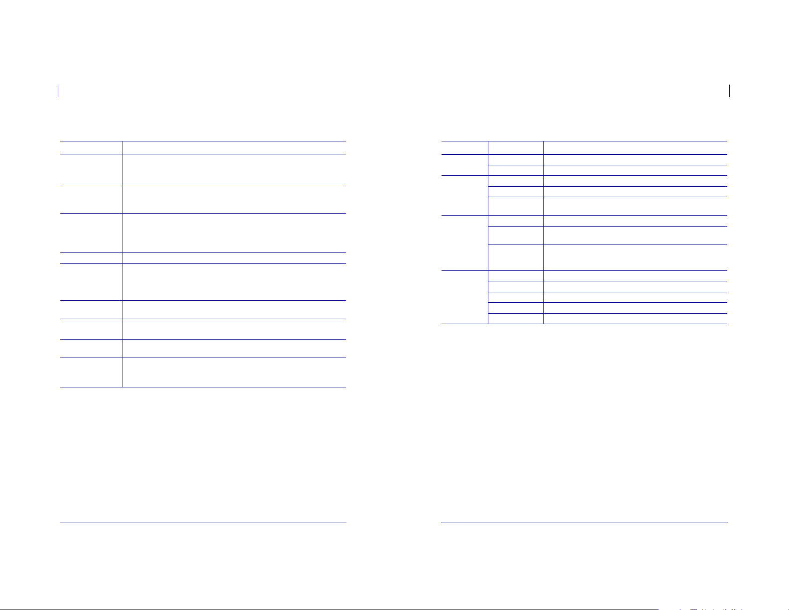
How This Document Is Organized
The User Guide is set up as follows:
Section Description
Introduction on page 15 This section shows the operational controls and
Printer Setup on page 23 This section provides the tasks that you must
Operations on page 37 This section provides the procedures for loading
Configuration on page 63 This section describes the control panel parameters
Routine Maintenance onpage 97 This section provides routine cleaning and
Troubleshooting onpage 109 This section provides information about errors that
Specifications on page 133 This section provides the features of and
location of major components used when loading
media.
complete and the issues that you must consider
before you load and configure your printer.
and calibrating the printer.
that are used to configure the printer for operation.
maintenance procedures.
you might need to troubleshoot. Assorted
diagnostic tests are included.
specifications for the printer.
5/12/08 ZM™ Series/RZ™ Series User Guide 79695L-002 Rev. A
79695L-002 Rev. A ZM™ Series/RZ™ Series User Guide 5/12/08
Page 6

About This Document
Bubbl edot ICG
Contacts
11
About This Document
Document Conventions
12
Contacts
You can contact Zebra Technologies Corporation at the following:
Web Site
http://www.zebra.com
Technical Support via the Internet is available 24 hours per day, 365 days per year. Go to
http://www.zebra.com/support.
The Americas
Regional Headquarters Technical Support Customer Service Dept.
Zebra Technologies International, LLC
333 Corporate Woods Parkway
Vernon Hills, Illinois 60061.3109 U.S.A
T: +1 847 793 2600
Toll-free +1 800 423 0422
F: +1 847 913 8766
Europe, Africa, Middle East, and India
Regional Headquarters Technical Support Internal Sales Dept.
Zebra Technologies Europe Limited
Zebra House
The Valley Centre, Gordon Road
High Wycombe
Buckinghamshire, HP13 6EQ, UK
T: +44 (0)1494 472872
F: +44 (0) 1494 450103
Asia Pacific
Regional Headquarters Technical Support Customer Service
Zebra Technologies Asia Pacific, LLC
120 Robinson Road
#06-01 Parakou Building
Singapore 068913
T: +65 6858 0722
F: +65 6885 0838
T: +1 877 ASK ZEBRA (275 9327)
F: +1 847 913 2578
Hardware: ts1@zebra.com
Software: ts3@zebra.com
T: +44 (0) 1494 768298
F: +44 (0) 1494 768210
Germany: Tsgermany@zebra.com
France: Tsfrance@zebra.com
Spain/Portugal: Tsspain@zebra.com
All other areas: Tseurope@zebra.com
T: +65 6858 0722
F: +65 6885 0838
E: China: tschina@zebra.com
All other areas:
tsasiapacific@zebra.com
For printers, parts, media, and ribbon, please
call your distributor, or contactus.
T: +1 877 ASK ZEBRA (275 9327)
E: clientcare@zebra.com
For printers, parts, media, and ribbon, please
call your distributor, or contactus.
T: +44 (0) 1494 768316
F: +44 (0) 1494 768244
E: cseurope@zebra.com
For printers, parts, media, and ribbon, please
call your distributor, or contactus.
T: +65 6858 0722
F: +65 6885 0836
Document Conventions
The following conventions are used throughout this document to convey certain information.
Alternate Color (online only) Cross-references contain hot links to other sections in this
guide. If you are viewing this guide online in .pdf format, you can click the cross-reference
(blue text) to jump directly to its location.
LCD Display Examples Text from a printer’s Liquid Crystal Display (LCD) appears in
Command Line Examples Command line examples appear in Courier New font. For
example, type
Files and Directories File names and directories appear in Courier New font. For
example, the
Icons Used
Caution • Warns you of the potential for electrostatic discharge.
Caution • Warns you of a potential electric shock situation.
Caution • Warns you of a situation where excessive heat could cause a burn.
Caution • Advises you that failure to take or avoid a specific action could result in physical
harm to you.
Caution • (No icon) Advises you that failure to take or avoid a specific action could result in
physical harm to the hardware.
Important • Advises you of information that is essential to complete a task.
Note • Indicates neutral or positive information that emphasizes or supplements important
points of the main text.
font.
ZTools to get to the Post-Install scripts in the bin directory.
Zebra<version number>.tar file and the /root directory.
5/12/08 ZM™ Series/RZ™ Series User Guide 79695L-002 Rev. A
Example • Provides an example, often a scenario, to better clarify a section of text.
5/12/08 ZM™ Series/RZ™ Series User Guide 79695L-002 Rev. A
Page 7
About This Document
13
Document Conventions
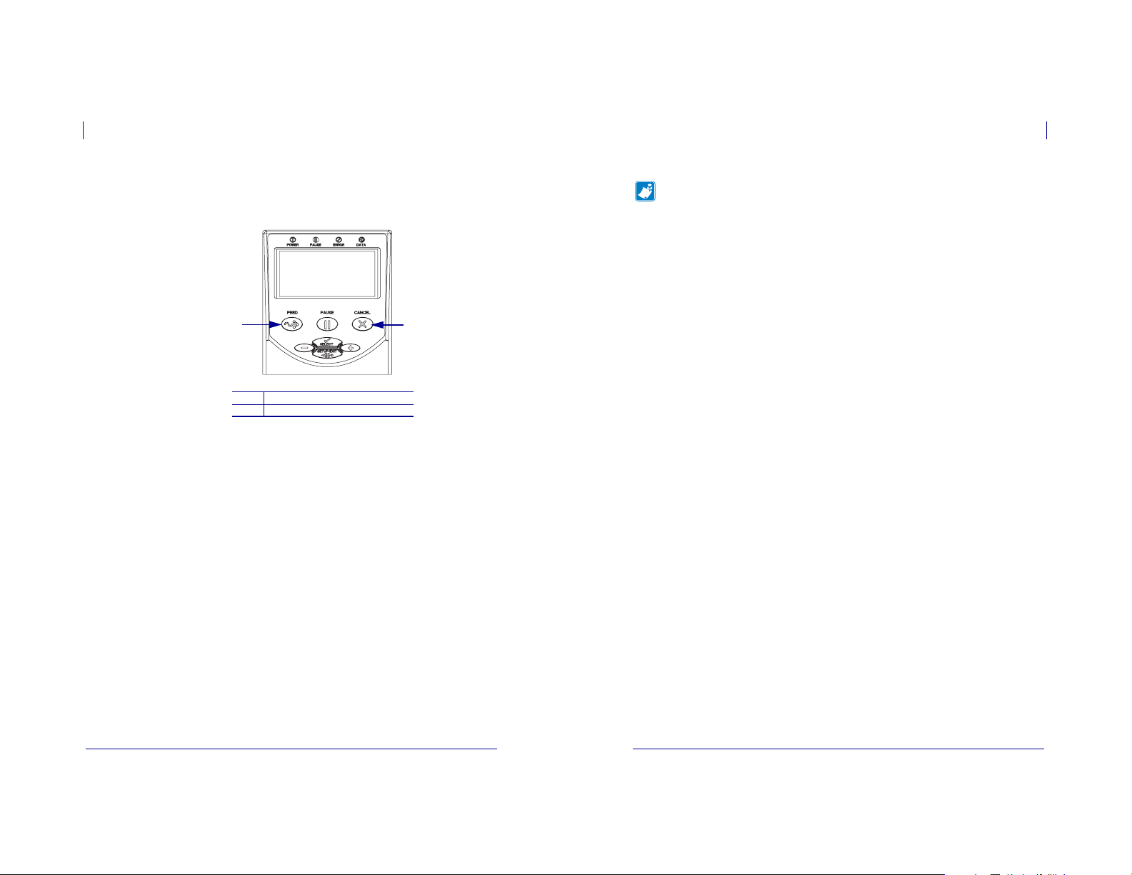
Illustration Callouts Callouts are used when an illustration contains information that needs
to be labeled and described. A table that contains the labels and descriptions follows the
graphic. Figure 1 provides an example.
Figure 1 • Sample Figure with Callouts
21
FEED button
1
CANCEL button
2
About This Document
Document Conventions
Notes • ___________________________________________________________________
__________________________________________________________________________
__________________________________________________________________________
__________________________________________________________________________
__________________________________________________________________________
__________________________________________________________________________
__________________________________________________________________________
__________________________________________________________________________
__________________________________________________________________________
__________________________________________________________________________
14
79695L-002 Rev. A ZM™ Series/RZ™ Series User Guide 5/12/08
5/12/08 ZM™ Series/RZ™ Series User Guide 79695L-002 Rev. A
Page 8
1
Introduction
This section shows the operational controls and location of major components used when
loading media.
Contents
External View. . . . . . . . . . . . . . . . . . . . . . . . . . . . . . . . . . . . . . . . . . . . . . . . . . . . . . . . . . 16
Printer Media Compartment. . . . . . . . . . . . . . . . . . . . . . . . . . . . . . . . . . . . . . . . . . . . . . . 17
Control Panel . . . . . . . . . . . . . . . . . . . . . . . . . . . . . . . . . . . . . . . . . . . . . . . . . . . . . . . . . . 18
Control Panel Buttons . . . . . . . . . . . . . . . . . . . . . . . . . . . . . . . . . . . . . . . . . . . . . . . . . 19
Control Panel Lights. . . . . . . . . . . . . . . . . . . . . . . . . . . . . . . . . . . . . . . . . . . . . . . . . . . 20
Printer Language Modes . . . . . . . . . . . . . . . . . . . . . . . . . . . . . . . . . . . . . . . . . . . . . . . . . 21
External View
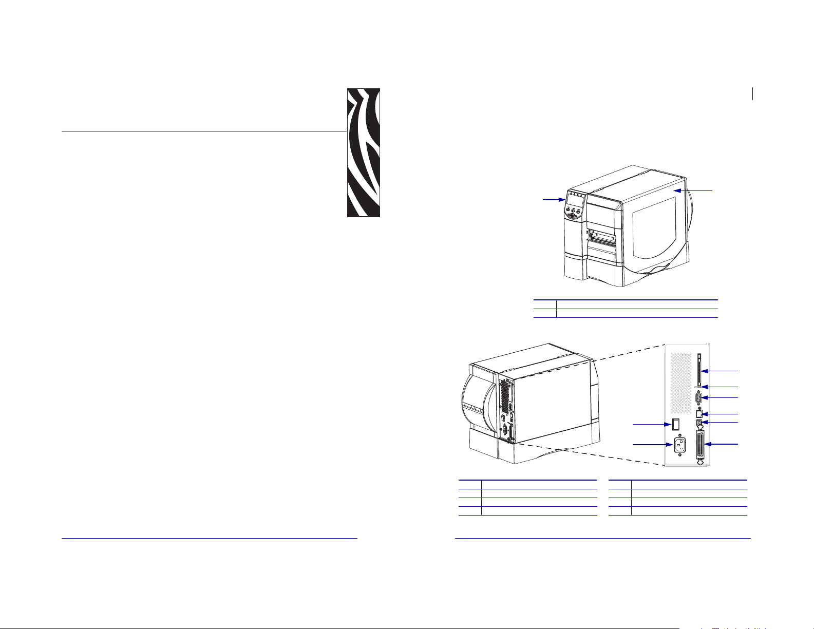
Figure 2 and Figure 3 show the components and connections on the outside of the printer.
1
1
2
Figure 2 • Front of Printer
Control panel
Media door
Figure 3 • Rear of Printer
Introduction
External View
2
1
16
3
4
5
6
7
5/12/08 ZM™ Series/RZ™ Series User Guide 79695L-002 Rev. A
2
Power switch (O = off, I = on)
1
AC power connector
2
Wireless print server card slot (Ethernet)
3
Wireless card ejector button
4
5/12/08 ZM™ Series/RZ™ Series User Guide 79695L-002 Rev. A
Serial port
5
Internal wired print server port (Ethernet)
6
USB port
7
Parallel port
8
8
Page 9
Printer Media Compartment
Introduction
17
Introduction
Control Panel
18
Printer Media Compartment
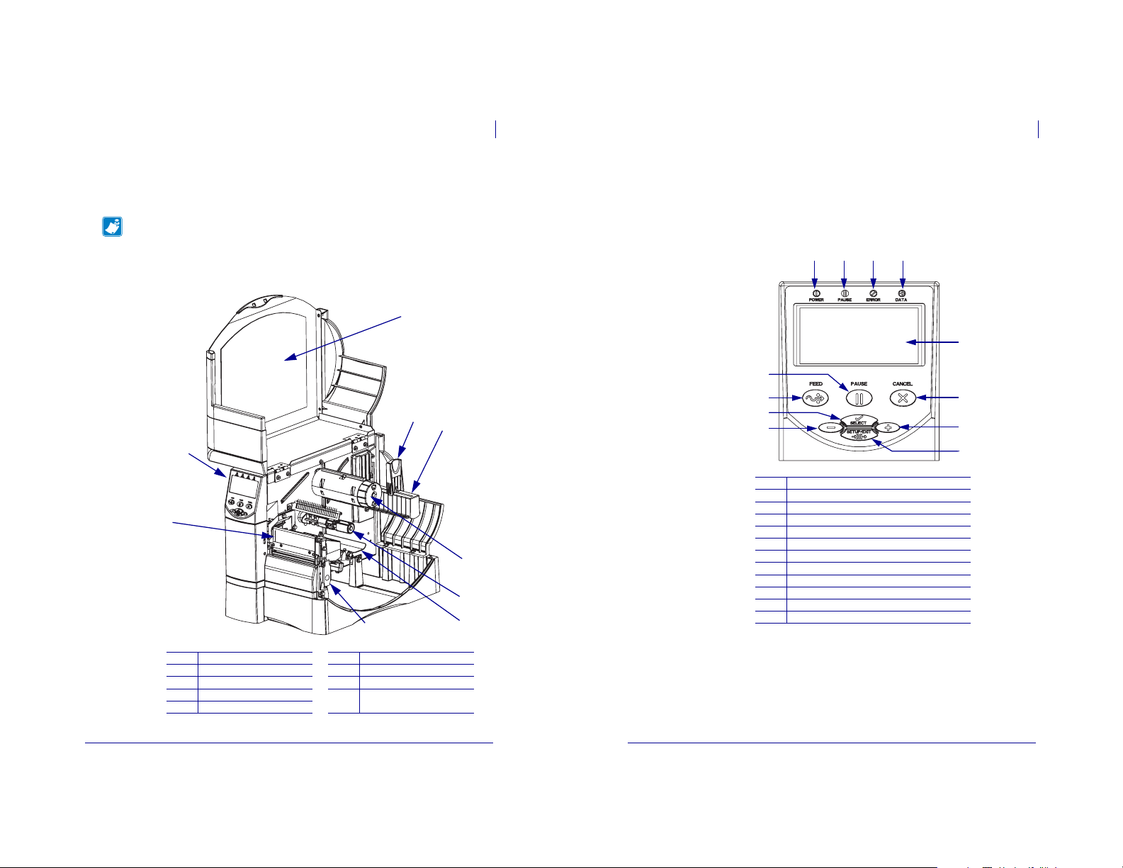
Figure 4 shows the components inside the media compartment of your printer. Depending on
installed options, your printer may look slightly different.
Note • For optimal printing quality and proper printer performance across our product line,
Zebra strongly recommends the use of genuine Zebra™ supplies as part of the total solution.
Specifically, the ZM400, ZM600, RM400, and RM600 are designed to work only with
genuine Zebra™ printheads, thus maximizing safety and print quality.
Figure 4 • Printer Components
2
1
Control Panel
The control panel contains the lights that indicate basic operation and the buttons that you may
need to press during basic operation. The control panel buttons and lights are labeled in
Figure 5. Descriptions for each are located in Table 1 and Table 2.
Figure 5 • Control Panel
1 2 3 4
3
5
12
11
4
5
6
7
9
8
10
9
1
2
3
4
5
6
7
8
9
10
11
12
Power LED
Pause LED
Error LED
Data LED
LCD
CANCEL button
PLUS (+) button
SETUP/EXIT button
MINUS (–) button
SELECT button
FEED button
PAUSE button
6
7
8
Printhead assembly
1
Control panel
2
Media door
3
Media supply guide
4
Media supply hanger
5
5/12/08 ZM™ Series/RZ™ Series User Guide 79695L-002 Rev. A
Ribbon take-up spindle
6
Ribbon supply spindle
7
Dancer assembly
8
Printhead release latch
9
5/12/08 ZM™ Series/RZ™ Series User Guide 79695L-002 Rev. A
Page 10
19
Introduction
Control Panel
Introduction
Control Panel
20
Control Panel Buttons
Button Function
FEED
PAUSE
CANCEL
SETUP/EXIT
SELECT
PLUS (+)
(scroll mode)
PLUS (+)
(change mode)
MINUS (–)
(scroll mode)
MINUS (–)
(change mode)
Forces the printer to feed one blank label each time the button is pressed.
• Printer not printing: one blank label immediately feeds.
• Printing: one blank label feeds after the current batch of labels is complete.
Starts and stops the printing process.
• Printer not printing: no printing occurs. (Press
• Printing: printing stops after the current label is complete.
Cancels print jobs when the printer is paused.
• Printer not printing: the next stored label format does not print.
• Printing: current label completes printing, and the next label format is cancelled.
Press and hold for several seconds to cancel all print jobs in memory.
Enters and exits the configuration mode.
Toggles the function of PLUS (+) and MINUS (–) between the Scroll and Change
Modes.
• Press once to use
• Press again to use
Scrolls to the next selection.
• Increases the value.
• Performs the action on the bottom right of the LCD.
Scrolls to the previous selection.
• Decreases the value.
• Moves to the next available digit in a number.
• Performs the action on the bottom left of the LCD.
Table 1 • Control Panel Buttons
PAUSE again to resume printing.)
PLUS (+) and MINUS (–) to change the values of the selection.
PLUS (+) and MINUS (–) to scroll through the menu items.
Control Panel Lights
Table 2 • Control Panel Lights
Light Status Indication
POWER Off The printer is off, or no power is applied.
On The printer is on.
PAUSE Off Normal printer operation.
On The printer has stopped all printing operations.
Flashing The Pause light flashes when initializing FLASH memory and in
ERROR Off Normal printer operation (no errors).
On An error condition is preventing printing. This includes
Flashing An error condition exists, but printing is allowed to continue. This
DATA Off Normal printer operation (no data being received or processed).
One flash
Slow flashing The printer cannot accept more data from the host.
Fast flashing The printer is receiving data.
On A partial format has been received and no subsequent data activity.
Peel-Off Mode when the label is available.
OUT
and RIBBON OUT errors.
RIBBON IN warning, HEAD UNDER TEMP warning,
includes
and
HEAD OVER TEMP error.
CANCEL was pressed and a format is successfully cancelled.
MEDIA
79695L-002 Rev. A ZM™ Series/RZ™ Series User Guide 5/12/08
5/12/08 ZM™ Series/RZ™ Series User Guide 79695L-002 Rev. A
Page 11

Printer Language Modes
Depending on how your printer was ordered, it came from the factory with firmware that
operates in or allows you to use certain commands for one of the following printer languages:
• Zebra Programming Language (ZPL
®
•Eltron
Programming Language (EPL™)
Firmware Downloads
You may download firmware to the printer at any time to change from one printer langua ge to
another. For the latest firmware versions and instructions for downloading them, go to
http://www.zebra.com/firmware.
Note • When the printer changes from one printer language to another, error messages may
appear on the LCD, and some control panel lights may activate in error mode. You may
ignore these error messages and lights. When the firmware download is complete, reboot the
printer and then load printer defaults to return the printer to Operating mode.
Additional Printer Language Information
The following manuals contain specific information about the different printer language
modes. Copies of these manuals are on the CD that came with your printer and at
http://www.zebra.com/manuals.
®
•ZPL II
Programming Guide
• EPL2™ Programming Guide
Introduction
Printer Language Modes
®
)
21
Introduction
22
Printer Language Modes
Notes • ___________________________________________________________________
__________________________________________________________________________
__________________________________________________________________________
__________________________________________________________________________
__________________________________________________________________________
__________________________________________________________________________
__________________________________________________________________________
__________________________________________________________________________
__________________________________________________________________________
__________________________________________________________________________
5/12/08 ZM™ Series/RZ™ Series User Guide 79695L-002 Rev. A
79695L-002 Rev. A ZM™ Series/RZ™ Series User Guide 5/12/08
Page 12

2
Printer Setup
This section provides the tasks that you must complete and the issues that you must consider
before you load and configure your printer.
Contents
Before You Begin. . . . . . . . . . . . . . . . . . . . . . . . . . . . . . . . . . . . . . . . . . . . . . . . . . . . . . . 24
Handling the Printer . . . . . . . . . . . . . . . . . . . . . . . . . . . . . . . . . . . . . . . . . . . . . . . . . . . . . 25
Unpack and Inspect the Printer . . . . . . . . . . . . . . . . . . . . . . . . . . . . . . . . . . . . . . . . . . 25
Store the Printer. . . . . . . . . . . . . . . . . . . . . . . . . . . . . . . . . . . . . . . . . . . . . . . . . . . . . . 25
Ship the Printer . . . . . . . . . . . . . . . . . . . . . . . . . . . . . . . . . . . . . . . . . . . . . . . . . . . . . . 25
Select a Site for the Printer . . . . . . . . . . . . . . . . . . . . . . . . . . . . . . . . . . . . . . . . . . . . . . . 26
Select a Surface. . . . . . . . . . . . . . . . . . . . . . . . . . . . . . . . . . . . . . . . . . . . . . . . . . . . . . 26
Provide Proper Operating Conditions . . . . . . . . . . . . . . . . . . . . . . . . . . . . . . . . . . . . . 26
Allow Proper Space . . . . . . . . . . . . . . . . . . . . . . . . . . . . . . . . . . . . . . . . . . . . . . . . . . . 26
Provide a Data Source. . . . . . . . . . . . . . . . . . . . . . . . . . . . . . . . . . . . . . . . . . . . . . . . . 26
Provide a Power Source . . . . . . . . . . . . . . . . . . . . . . . . . . . . . . . . . . . . . . . . . . . . . . . 26
Select a Data Communication Interface. . . . . . . . . . . . . . . . . . . . . . . . . . . . . . . . . . . . . . 27
Data Cables and Wireless Cards. . . . . . . . . . . . . . . . . . . . . . . . . . . . . . . . . . . . . . . . . 28
Connect the Printer to the Computer or Network. . . . . . . . . . . . . . . . . . . . . . . . . . . . . 28
Connect the Printer to a Power Source . . . . . . . . . . . . . . . . . . . . . . . . . . . . . . . . . . . . . . 31
Power Cord Specifications. . . . . . . . . . . . . . . . . . . . . . . . . . . . . . . . . . . . . . . . . . . . . . 32
Types of Media. . . . . . . . . . . . . . . . . . . . . . . . . . . . . . . . . . . . . . . . . . . . . . . . . . . . . . . . . 33
Ribbon Overview . . . . . . . . . . . . . . . . . . . . . . . . . . . . . . . . . . . . . . . . . . . . . . . . . . . . . . . 35
When to Use Ribbon . . . . . . . . . . . . . . . . . . . . . . . . . . . . . . . . . . . . . . . . . . . . . . . . . . 35
Coated Side of Ribbon. . . . . . . . . . . . . . . . . . . . . . . . . . . . . . . . . . . . . . . . . . . . . . . . . 35
Before You Begin
Review this checklist, and resolve any issues before you set up or use your printer.
Unpack and Inspect the Printer Have you unpacked the printer and inspected it for
damage? If you have not, see Unpack and Inspect the Printer onpage 25.
Select a Site Have you selected an appropriate location for the printer? If you have not,
see Select a Site for the Printer on page 26.
Connect to a Data Source Have you determined how the printer will connect to a
data source (usually a computer)? For more information, see Select a Data
Communication Interface on page 27.
Attach a Power Cord Do you have the correct power cord for your printer? If you are
unsure, see Power Cord Specifications onpage 32. To attach the power cord and connect
the printer to a power source, see Connect the Printer to a Power Source onpage 31.
Select Media Do you have the correct media for your application? If you are unsure,
see Types of Media onpage 33.
Select Ribbon Do you need to use ribbon, and is the appropriate ribbon available, if
needed? If you are unsure, see Ribbon Overview on page 35.
Printer Setup
Before You Begin
24
5/12/08 ZM™ Series/RZ™ Series User Guide 79695L-002 Rev. A
5/12/08 ZM™ Series/RZ™ Series User Guide 79695L-002 Rev. A
Page 13
Printer Setup
Handling the Printer
25
Select a Site for the Printer
Printer Setup
26
Handling the Printer
This section describes how to handle your printer.
Unpack and Inspect the Printer
When you receive the printer, immediately unpack it and inspect for shipping damage.
• Save all packing materials.
• Check all exterior surfaces for damage.
• Raise the media door, and inspect the media compartment for damage to components.
If you discover shipping damage upon inspection:
• Immediately notify the shipping company and file a damage report.
• Keep all packaging material for shipping company inspection.
• Notify your authorized Zebra reseller
Important • Zebra Technologies Corporation is not responsible for any damage incurred
during the shipment of the equipment and will not repair this damage under warranty.
Store the Printer
If you are not placing the printer into immediate operation, repackage it using the original
packing materials. You may store the printer under the conditions shown in Table 3.
Table 3 • Storage Temperature and Humidity
Temperature Relative Humidity
–40°F to 140°F (–40° to 60°C) 5% to 85% non-condensing
Ship the Printer
If you must ship the printer:
• Turn off (
• Remove any media, ribbon, or loose objects from the printer interior.
• Close the printhead.
• Carefully pack the printer into the original container or a suitable alternate container to
O) the printer, and disconnect all cables.
avoid damage during transit. A shipping container can be purchased from Zebra if the
original packaging has been lost or destroyed.
Select a Site for the Printer
Consider the following when selecting an appropriate location for your printer.
Select a Surface
Select a solid, level surface of sufficient size and strength to accommodate the printer and
other equipment (such as a computer), if necessary. The choices include a table, countertop,
desk, or cart. For the printer’s weight and dimensions, see General Specifications onpage 134.
Provide Proper Operating Conditions
This printer is designed to function in a wide range of environmental and electrical conditions,
including a warehouse or factory floor. For more information on the required conditions, see
General Specifications on page 134.
Table 4 shows the temperature and relative humidity requirements for the printer when it is
operating.
Table 4 • Operating Temperature and Humidity
Mode Temperature Relative Humidity
Thermal Transfer 40° to 104°F (5° to 40°C) 20 to 85% non-condensing.
Direct Thermal 32° to 104°F (0° to 40°C) 20 to 85% non-condensing
Allow Proper Space
The printer should have enough space around it for you to be able to open the media door. To
allow for proper ventilation and cooling, leave open space on all sides of the printer.
Caution • Do not place any padding or cushioning material behind or under the printer
because this restricts air flow and could cause the printer to overheat.
Provide a Data Source
If the printer will be located away from the data source (such as a computer), the selected site
must provide the appropriate connections to that data source. For more information on the
types of communication interfaces and their limitations, see Select a Data Communication
Interface on page 27.
Provide a Power Source
Place the printer within a short distance of a power outlet that is easily accessible.
5/12/08 ZM™ Series/RZ™ Series User Guide 79695L-002 Rev. A
5/12/08 ZM™ Series/RZ™ Series User Guide 79695L-002 Rev. A
Page 14
Select a Data Communication Interface
Printer Setup
27
Printer Setup
28
Select a Data Communication Interface
Select a Data Communication Interface
Table 5 provides basic information about data communication interfaces that you can use to
connect your printer to a computer. You may send label formats to the printer through any data
communication interface that is available. Select an interface that is supported by both your
printer and your computer or your Local Area Network (LAN).
Table 5 • Characteristics of the Data Communication Interfaces
Interface
RS-232 Serial Standard • Maximum cable length of 50 ft (15.24 m).
IEEE 1284
Bidirectional Parallel
USB Standard • Maximum cable length of 16.4 ft (5 m).
Internal wired
Ethernet print server
Wireless Ethernet
print server
Standard or
Optional on
Printer
Characteristics
• You may need to change printer parameters to match the host
computer.
• You need to use a null-modem adaptor to connect to the printer
if using a standard modem cable.
Standard • Maximum cable length of 10 ft (3 m).
• Recommended cable length of 6 ft (1.83 m).
• No printer parameter changes required to match the host
computer.
• No printer parameter changes required to match the host
computer.
Optional • Can print to the printer from any computer on your LAN.
• Can communicate with the printer through the printer’s web
pages.
• Computer must be equipped with an Ethernet board.
• The printer must be configured to use your LAN.
Optional • Can print to the printer from any computer on your Wireless
Local Area Network (WLAN).
• Can communicate with the printer through the printer’s web
pages.
• Computer must be equipped with an Ethernet board.
• The printer must be configured to use your WLAN.
Data Cables and Wireless Cards
You must supply all data cables or wireless cards for your application.
Data Cables Ethernet cables do not require shielding, but all other data cables must be fully
shielded and fitted with metal or metallized connector shells. Unshielded data cables may
increase radiated emissions above the regulated limits.
To minimize electrical noise pickup in the cable:
• Keep data cables as short as possible.
• Do not bundle the data cables tightly with the power cords.
• Do not tie the data cables to power wire conduits.
Wireless Cards For supported wireless cards, refer to the ZebraNet Wireless Print Server
and Wireless Plus Print Server User Guide. A copy of the manual is available at
http://www.zebra.com/manuals or on the userCD that came with your printer.
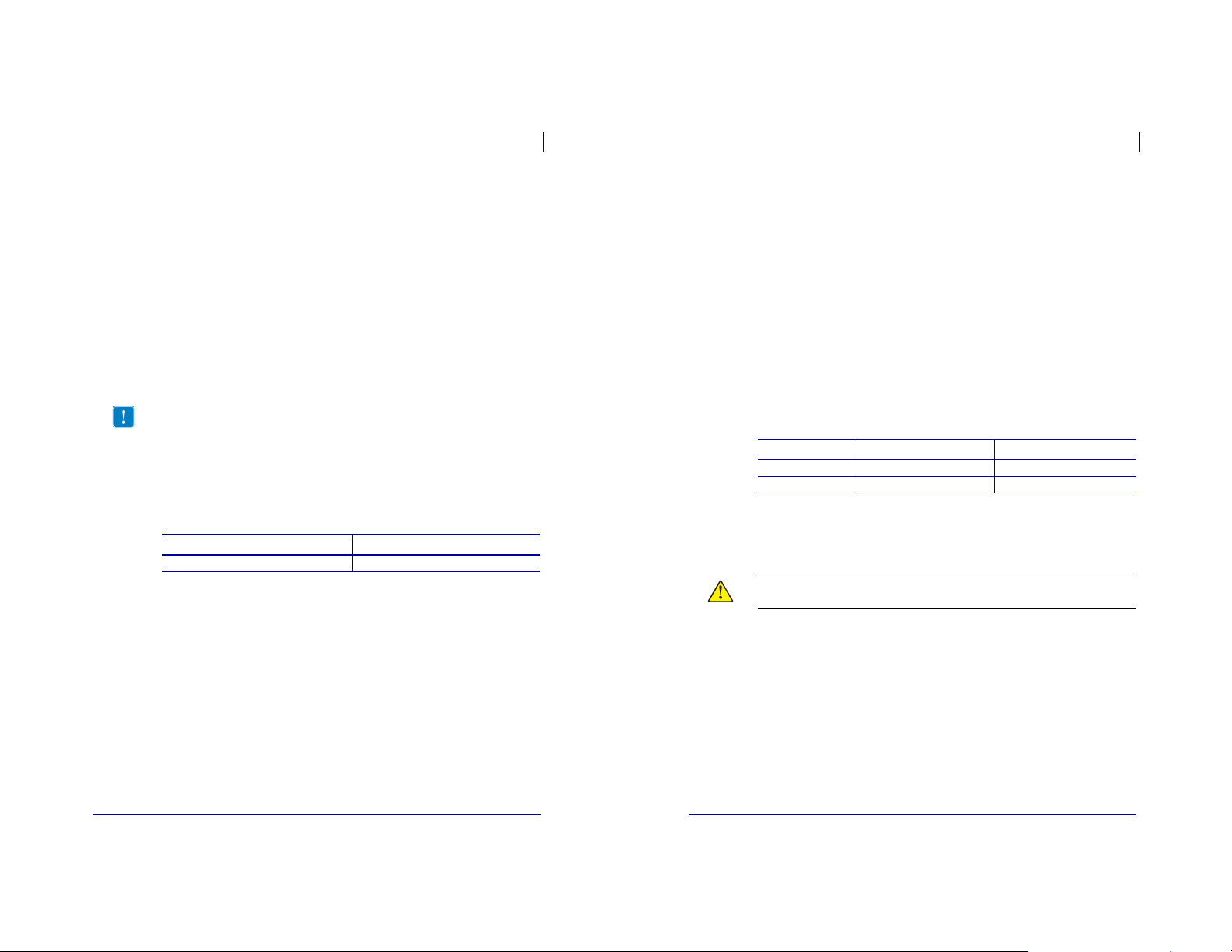
Connect the Printer to the Computer or Network
Table 6 shows how to connect the different types of data cables to your printer and computer.
The connectors on the back of your computer may be in different locations than on the sample
computer shown in this section. For another view of the connectors on the printer, see Figure3
on page 16.
Caution • Ensure that the printer power is off (O) before connecting data communications
cables. Connecting a data communications cable while the power is on (
printer.
Table 6 • Connecting the Printer to a Computer or Network
Interface Connection and Configuration
RS-232 Serial The baud rate, number of data and stop bits, the parity, and the
XON/XOFF or DTR control must match those of the host computer. See
Control Panel Parameters onpage69 to view or change these parameters.
I) may damage the
5/12/08 ZM™ Series/RZ™ Series User Guide 79695L-002 Rev. A
79695L-002 Rev. A ZM™ Series/RZ™ Series User Guide 5/12/08
Page 15

Select a Data Communication Interface
Printer Setup
29
Printer Setup
30
Select a Data Communication Interface
Table 6 • Connecting the Printer to a Computer or Network (Continued)
Interface Connection and Configuration
IEEE 1284
Bidirectional
Parallel
No additional configuration is necessary.
USB No additional configuration is necessary.
Caution • Be careful not to plug the USB cable into the wired Ethernet
print server connector on the printer because doing so will damage the
connector.
Table 6 • Connecting the Printer to a Computer or Network (Continued)
Interface Connection and Configuration
Internal wired
Ethernet print
server
Wireless
Ethernet print
server
Refer to the ZebraNet 10/100 Print Server User and Reference Guide for
configuration instructions. A copy of this manual is available at
http://www.zebra.com/manuals or on the user CD that came with your
printer.
Refer to the ZebraNet Wireless Print Server and Wireless Plus Print
Server User Guide for configuration instructions. A copy of this manual is
available at http://www.zebra.com/manuals or on the user CD that came
with your printer.
5/12/08 ZM™ Series/RZ™ Series User Guide 79695L-002 Rev. A
79695L-002 Rev. A ZM™ Series/RZ™ Series User Guide 5/12/08
Page 16
Connect the Printer to a Power Source
Printer Setup
31
Printer Setup
32
Connect the Printer to a Power Source
Connect the Printer to a Power Source
The AC power cord must have a three-prong female connector on one end that plugs into the
mating AC power connector at the rear of the printer. If a power cable was not included with
your printer, refer to Power Cord Specifications onpage32.
Caution • For personnel and equipment safety, always use an approved three-conductor
power cord specific to the region or country intended for installation. This cord must use an
IEC 320 female connector and the appropriate region-specific three-conductor grounded
plug configuration.
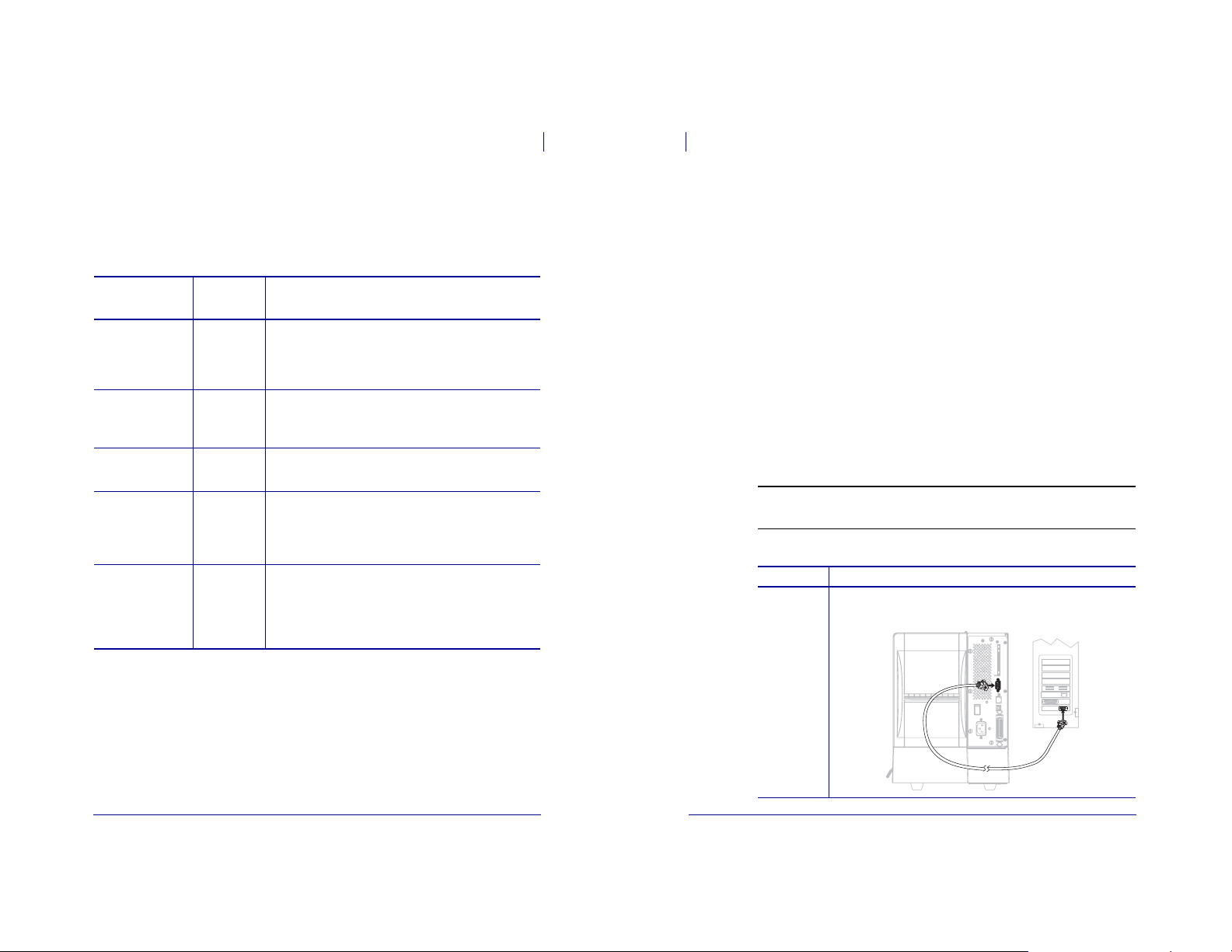
To connect the printer to a power source, complete these steps:
1. Toggle the printer power switch to the off (O) position.
2. Plug the power cord into the AC power connector (1) on the rear of the printer.
3. Plug the other end of the power cord into a power outlet near the printer.
4. Turn on (I) the printer.
Power Cord Specifications
Caution • For personnel and equipment safety, always use an approved three-conductor
power cord specific to the region or country intended for installation. This cord must use an
IEC 320 female connector and the appropriate region-specific, three-conductor grounded
plug configuration.
Depending on how your printer was ordered, a power cord may or may not be included. If one
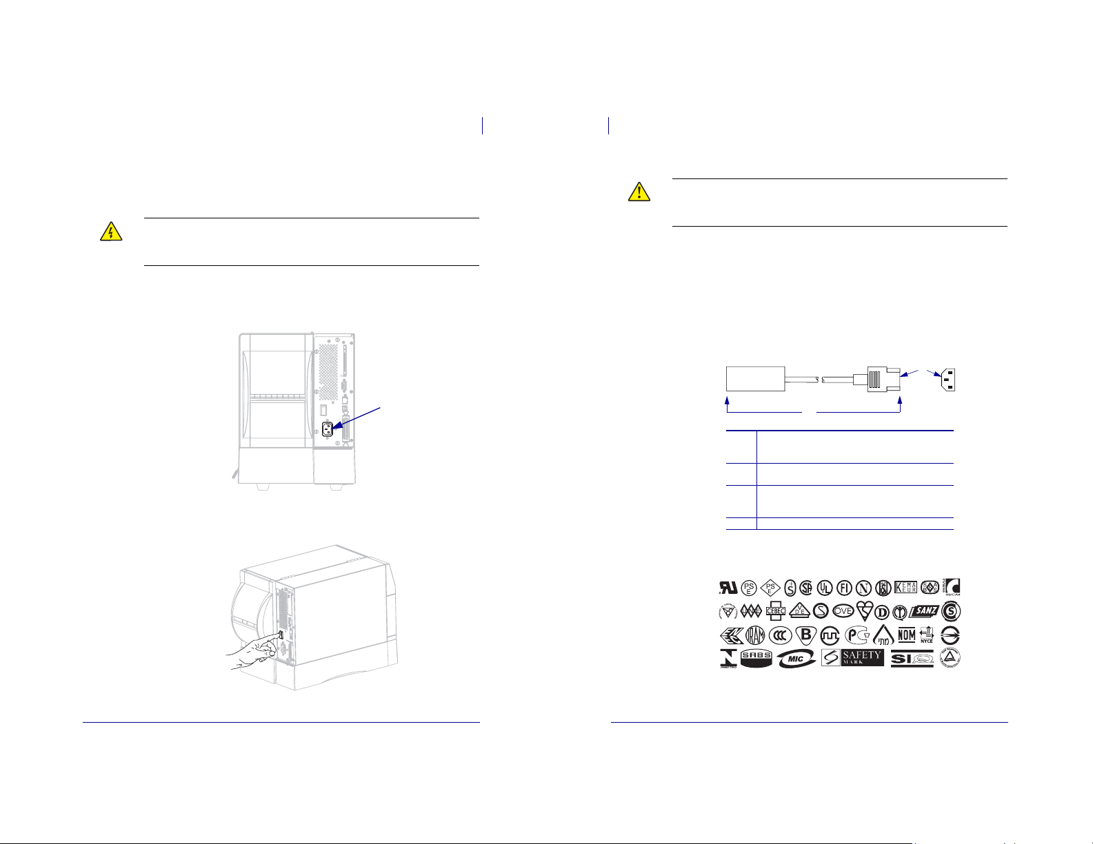
is not included or if the one included is not suitable for your requirements, see Figure6 and
refer to the following guidelines:
• The overall cord length must be less than 9.8 ft. (3 m).
• The cord must be rated for at least 10 A, 250 V.
• The chassis ground (earth) must be connected to ensure safety and reduce electromagnetic
interference.
Figure 6 • Power Cord Specifications
1
1
AC power plug for your country—This should bear
1
the certification mark of at least one of the known
international safety organizations (Figure 7).
3-conductor HAR cable or other cable approved for
2
your country.
IEC 320 connector—This should bear the
3
certification mark of at least one of the known
international safety organizations (Figure 7).
Length d 9.8 ft. (3 m). Rating 10 Amp, 250 VAC.
4
2
4
3
The control panel LCD and lights activate, indicating that the printer is booting up.
5/12/08 ZM™ Series/RZ™ Series User Guide 79695L-002 Rev. A
Figure 7 • International Safety Organization Certifications
79695L-002 Rev. A ZM™ Series/RZ™ Series User Guide 5/12/08
Page 17
Printer Setup
Types of Media
33
34
Printer Setup
Types of Media
Types of Media
Important • Zebra strongly recommends the use of Zebra-brand supplies for continuous
high-quality printing. A wide range of paper, polypropylene, polyester, and vinyl stock has
been specifically engineered to enhance the printing capabilities of the printer and to prevent
premature printhead wear. To purchase supplies, go to http://www.zebra.com/howtobuy.
Your printer can use various types of media:
• Standard media—Most standard media uses an adhesive backing that sticks individual
labels or a continuous length of labels to a liner.
• Tag stock—Tags are usually made from a heavy paper. Tag stock does not have adhesive
or a liner, and it is typically perforated between tags.
• Radio frequency identification (RFID) “smart” media—RFID
media can be used in a printer that is equipped with an RFID
reader/encoder. RFID labels are made from the same materials and
adhesives as non-RFID labels. Each label has an RFID transponder
(sometimes called an “inlay”), made of a chip and an antenna,
embedded between the label and the liner. The shape of the transponder varies by
manufacturer and is visible through the label. All “smart” labels have memory that can be
read, and many have memory that can be encoded.
Important • Transponder placement within a label depends on the transponder type and
the printer model. Make sure that you are using the correct “smart” media for your printer.
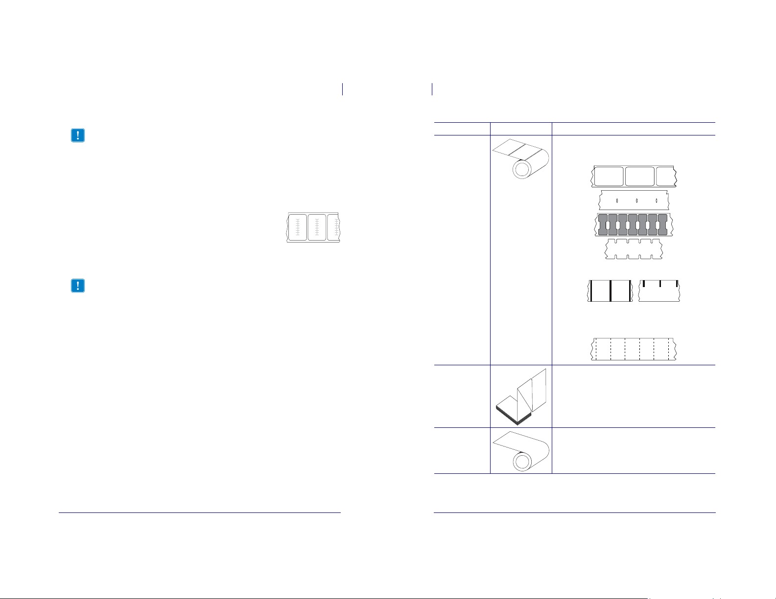
Table 7 describes roll and fanfold media. Roll media is loaded into the printer while fanfold
media may be located inside or outside of the printer.
Table 7 • Roll and Fanfold Media
Media Type How It Looks Description
Non-Continuous
Roll Media
Roll media is wound on a 3-in. (76-mm) core. Individual
labels are separated by one or more of the following methods:
• Web media separates labels by gaps, holes, or notches.
• Black mark media uses pre-printed black marks on the back
side of the media to indicate label separations.
• Perforated media has perforations that allow the labels or
tags to be separated from each other easily. The media may
also have black marks or other separations between labels
or tags.
Non-Continuous
Fanfold Media
Fanfold media is folded in a zigzag pattern. Fanfold media can
have the same label separations as non-continuous roll media.
The separations would fall on or near the folds.
5/12/08 ZM™ Series/RZ™ Series User Guide 79695L-002 Rev. A
Continuous
Roll Media
79695L-002 Rev. A ZM™ Series/RZ™ Series User Guide 5/12/08
Roll media is wound on a 3-in. (76-mm) core.
Continuous roll media does not have gaps, holes, notches, or
black marks to indicate label separations. This allows the
image to be printed anywhere on the label. Sometimes a cutter
is used to cut apart individual labels.
Page 18
Printer Setup
Ribbon Overview
35
Printer Setup
36
Ribbon Overview
Ribbon Overview
Ribbon is a thin film that is coated on one side with wax, resin, or wax resin, which is
transferred to the media during the thermal transfer process. The media determines whether
you need to use ribbon and how wide the ribbon must be.
When ribbon is used, it must be as wide as or wider than the media being used. If the ribbon is
narrower than the media, areas of the printhead are unprotected and subject to premature wear.
When to Use Ribbon
Thermal transfer media requires ribbon for printing while direct thermal media does not.
Todetermine if ribbon must be used with a particular media, perform a media scratch test.
To perform a media scratch test, complete these steps:
1. Scratch the print surface of the media rapidly with your fingernail.
2. Did a black mark appear on the media?
If a black mark... Then the media is...
Does not appear on the media Thermal transfer. A ribbon is required.
Appears on the media Direct thermal. No ribbon is required.
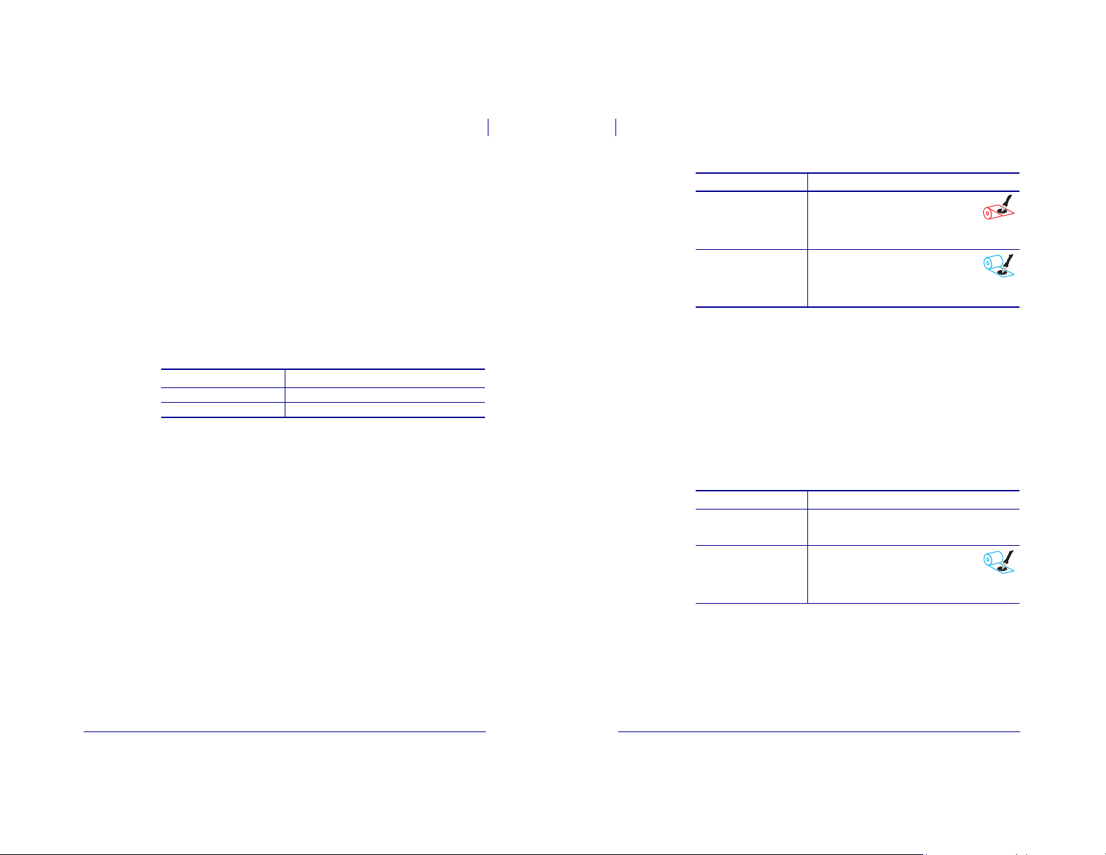
Coated Side of Ribbon
Ribbon can be wound with the coated side on the inside or outside. The ribbon used must
match the Thermal Transfer option installed. The standard Thermal Transfer option (black
ribbon spindle) uses ribbon coated on the outside, and the alternate Thermal Transfer option
(gray ribbon spindle) uses ribbon coated on the inside. If you are unsure which side of a
particular roll of ribbon is coated, perform an adhesive test or a ribbon scratch test to
determine which side is coated.
Adhesive Test
If you have labels available, perform the adhesive test to determine which side of a ribbon is
coated. This method works well for ribbon that is already installed.
To perform an adhesive test, complete these steps:
1. Peel a label from its liner.
2. Press a corner of the sticky side of the label to the outer surface of the roll of ribbon.
3. Peel the label off of the ribbon.
4. Observe the results. Did flakes or particles of ink from the ribbon adhere to the label?
If ink from the ribbon... Then...
Adhered to the label The ribbon is coated on the outside and can be
Did not adhere to the label The ribbon is coated on the inside and can be
used with the standard Thermal Transfer
option (black ribbon spindle). In the ribbon
loading procedure, instructions are marked
with this symbol.
used with the alternate Thermal Transfer
option (gray ribbon spindle). In the ribbon
loading procedure, instructions are marked
with this symbol.
Ribbon Scratch Test
Perform the ribbon scratch test when labels are unavailable.
To perform a ribbon scratch test, complete these steps:
1. Unroll a short length of ribbon.
2. Place the unrolled section of ribbon on a piece of paper with the outer surface of the
ribbon in contact with the paper.
3. Scratch the inner surface of the unrolled ribbon with your fingernail.
4. Lift the ribbon from the paper.
5. Observe the results. Did the ribbon leave a mark on the paper?
If the ribbon... Then...
Left a mark on the paper The ribbon is coated on the outside and can be used with
Did not leave a mark on the
paper
the standard Thermal Transfer option (black ribbon
spindle).
The ribbon is coated on the inside and can be
used with the alternate Thermal Transfer
option (gray ribbon spindle). In the ribbon
loading procedure, instructions are marked
with this symbol.
5/12/08 ZM™ Series/RZ™ Series User Guide 79695L-002 Rev. A
79695L-002 Rev. A ZM™ Series/RZ™ Series User Guide 5/12/08
Page 19
3
Operations
Print Modes and Printer Options
The printer can use different print modes and options for label removal (Table 8). Use a print
mode that matches the media being used and the printer options available. For more
information on the types of media, see Types of Media onpage 33. To select a print mode, see
Select Print Mode on page 73.
Print Modes and Printer Options
Operations
38
This section provides the procedures for loading and calibrating the printer.
Note • Complete the tasks and resolve the issues in Printer Setup on page 23 before
operating the printer.
Contents
Print Modes and Printer Options . . . . . . . . . . . . . . . . . . . . . . . . . . . . . . . . . . . . . . . . . . . 38
Print Mode Descriptions and Printer Requirements. . . . . . . . . . . . . . . . . . . . . . . . . . . 38
Media Paths. . . . . . . . . . . . . . . . . . . . . . . . . . . . . . . . . . . . . . . . . . . . . . . . . . . . . . . . . 39
Load Media . . . . . . . . . . . . . . . . . . . . . . . . . . . . . . . . . . . . . . . . . . . . . . . . . . . . . . . . . . . 41
Beginning Steps for all Print Modes and Printer Options. . . . . . . . . . . . . . . . . . . . . . . 41
Additional Steps for Tear-Off Mode . . . . . . . . . . . . . . . . . . . . . . . . . . . . . . . . . . . . . . . 44
Additional Steps for Peel-Off Mode (with or without Liner Take-Up) . . . . . . . . . . . . . . 45
Additional Steps for Cutter or Delayed Cut Mode . . . . . . . . . . . . . . . . . . . . . . . . . . . . 50
Additional Steps for Rewind Mode. . . . . . . . . . . . . . . . . . . . . . . . . . . . . . . . . . . . . . . . 51
Load Ribbon. . . . . . . . . . . . . . . . . . . . . . . . . . . . . . . . . . . . . . . . . . . . . . . . . . . . . . . . . . . 55
Remove Used Ribbon . . . . . . . . . . . . . . . . . . . . . . . . . . . . . . . . . . . . . . . . . . . . . . . . . 59
Calibrate the Printer. . . . . . . . . . . . . . . . . . . . . . . . . . . . . . . . . . . . . . . . . . . . . . . . . . . . . 60
Auto Calibration . . . . . . . . . . . . . . . . . . . . . . . . . . . . . . . . . . . . . . . . . . . . . . . . . . . . . . 60
Manual Calibration. . . . . . . . . . . . . . . . . . . . . . . . . . . . . . . . . . . . . . . . . . . . . . . . . . . . 60
Adjust Printhead Pressure . . . . . . . . . . . . . . . . . . . . . . . . . . . . . . . . . . . . . . . . . . . . . . . . 61
Print Mode Descriptions and Printer Requirements
Table 8 • Print Modes and Printer Options
Print Mode When to Use/Printer Options Required Printer Actions
Tear-Off
(default setting)
Peel-Off Use only if the printer has the Peel-Off,
Cutter Use if the printer has a cutter option when
Delayed Cut Use if the printer has a cutter option when
Rewind Use if the printer has the Rewind option and
Linerless Peel Reserved for future options. Reserved for future options.
Linerless
Rewind
Use for most applications. This mode can
be used with any printer options and most
media types.
Liner Take-Up, or Rewind option.
you want the labels to be cut apart.
you want the printer to cut the labels apart
at a signal.
you want the labels to rewind on a core.
Reserved for future options. Reserved for future options.
The printer prints label formats as it
receives them. The printer operator can tear
off the printed labels any time after they
print.
The printer peels the label from the liner
during printing and then pauses until the
label is removed.
In Peel-Off mode, the liner exits the front of
the printer. In Peel-Off mode with Liner
Take-Up, the liner winds onto the liner
take-up spindle or the rewind spindle.
The printer prints a label and then cuts it
free.
The printer prints a label, pauses, and cuts
the label when it receives the ~JK (delayed
cut) ZPL command.
The printer prints without pausing between
labels. The media or liner is wound onto a
core after printing.
5/12/08 ZM™ Series/RZ™ Series User Guide 79695L-002 Rev. A
5/12/08 ZM™ Series/RZ™ Series User Guide 79695L-002 Rev. A
Page 20
Operations
39
Print Modes and Printer Options
Print Modes and Printer Options
Operations
40
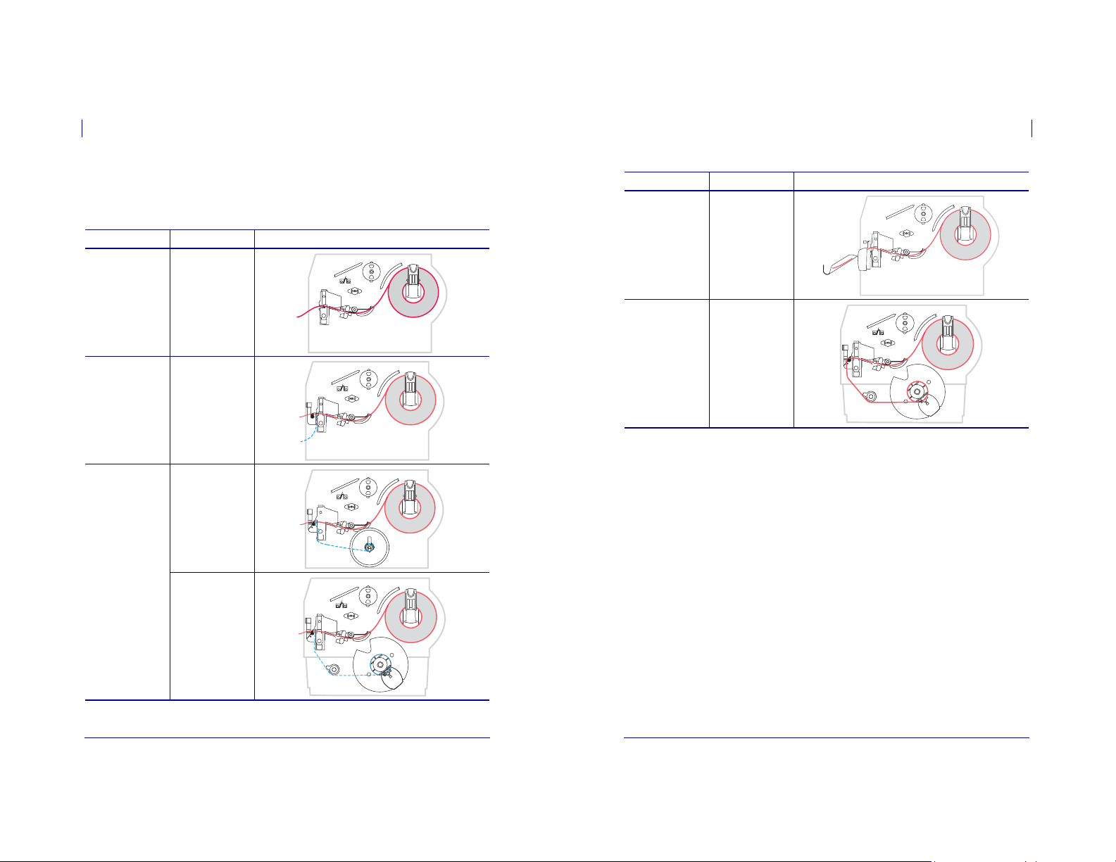
Media Paths
Table 9 shows the media paths for print mode and printer option combinations using roll
media. Fanfold media uses the same print modes and printer options as roll media.
Table 9 • Media Paths for Print Modes with Various Printer Options
Print Mode Printer Option Media Path
Tear-Off Printers with any
Peel-Off Peel, Liner take-up,
Peel-Off (with Liner
Take-Up)
printer options can
use Tear-Off mode
or Rewind
Liner take-up
Table 9 • Media Paths for Print Modes with Various Printer Options (Continued)
Print Mode Printer Option
Cutter or
Delayed Cut
Cutter (shown with
an optional catch
tray)
Media Path
Rewind Rewind
Red solid lines = media, Blue dotted lines = backing only
Rewind
Red solid lines = media, Blue dotted lines = backing only
79695L-002 Rev. A ZM™ Series/RZ™ Series User Guide 5/12/08
5/12/08 ZM™ Series/RZ™ Series User Guide 79695L-002 Rev. A
Page 21
41
Operations
Load Media
Operations
Load Media
42
Load Media
The beginning steps for loading media apply to all printers, including those that have the
peel-off, liner take-up, cutter, or rewind option. When you have completed these beginning
steps, continue with the media loading instructions for the print mode and printer options that
apply to you. For more information about print modes and printer options, see Print Modes
and Printer Options onpage 38.
Caution • While performing any tasks near an open printhead, remove all rings, watches,
hanging necklaces, identification badges, or other metallic objects that could touch the
printhead. You are not required to turn off the printer power when working near an open
printhead, but Zebra recommends it as a precaution. If you turn off the power, you will lose
all temporary settings, such as label formats, and you must reload them before you resume
printing.
Beginning Steps for all Print Modes and Printer Options
To begin loading media for all print modes and printer options, complete these
steps:
1. Press the printhead release latch to open the printhead assembly. Lift the printhead until it
latches open.
3. Insert media into the printer. Follow the instructions for roll or fanfold media, as
appropriate.
Roll Media
a. Remove and discard any tags or
labels that are dirty or that are held
by adhesives or tape.
b. Flip down the media supply guide. b. Feed the media through the rear or
c. Place the roll of media on the media
supply hanger. Push the roll as far
back as it will go.
Fanfold Media
a. Flip down the media supply guide.
bottom access slot.
Rear Feed
Bottom Feed
2. Slide out the media guide.
79695L-002 Rev. A ZM™ Series/RZ™ Series User Guide 5/12/08
d. Flip up the media supply guide. c. Drape the media over the media
5/12/08 ZM™ Series/RZ™ Series User Guide 79695L-002 Rev. A
supply hanger.
Page 22

43
Operations
Load Media
Operations
Load Media
44
Roll Media (Continued)
e. Slide in the media supply guide until
it touches the edge of the roll.
4. Feed the media under the dancer assembly (1), the upper media sensor (2), and the ribbon
sensor (3). Slide the media back until it touches the inside back wall of the upper media
sensor.
Fanfold Media (Continued)
d. Flip up the media supply guide.
e. Slide in the media supply guide until
it touches the edge of the media.
13 2
Additional Steps for Tear-Off Mode
After completing Beginning Steps for all Print Modes and Printer Options onpage 41,
continue with this section to operate the printer in Tear-Off mode.
To operate the printer in Tear-Off mode, complete these steps:
1. Slide in the media guide until it touches the outer edge of the media.
2. Set the printer to Tear-Off mode. See Select Print Mode on page 73 for instructions.
3. Close the printhead assembly.
5. Continue with the final instructions for the desired print mode. The print mode must be
compatible with the media being used and the printer options installed. See Print Mode
Descriptions and Printer Requirements onpage 38 for more information.
• Additional Steps for Tear-Off Mode on page 44
• Additional Steps for Peel-Off Mode (with or without Liner Take-Up) on page 45
• Additional Steps for Cutter or Delayed Cut Mode onpage 50
• Additional Steps for Rewind Mode onpage 51
79695L-002 Rev. A ZM™ Series/RZ™ Series User Guide 5/12/08
4. If the printer is paused (the Pause light is on), press PAUSE to enable printing.
5/12/08 ZM™ Series/RZ™ Series User Guide 79695L-002 Rev. A
Page 23

45
Operations
Load Media
Operations
Load Media
46
Additional Steps for Peel-Off Mode (with or without Liner Take-Up)
After completing Beginning Steps for all Print Modes and Printer Options onpage 41,
continue with this section to operate the printer in Peel-Off mode with or without liner take-up.
Your printer must have the Peel option, the Liner Take-Up option, or the Rewind option
installed. See Print Modes and Printer Options on page 38 for more information.
For additional procedures related to the rewind option, see Routine Maintenance for the
Rewind Option on page 106.
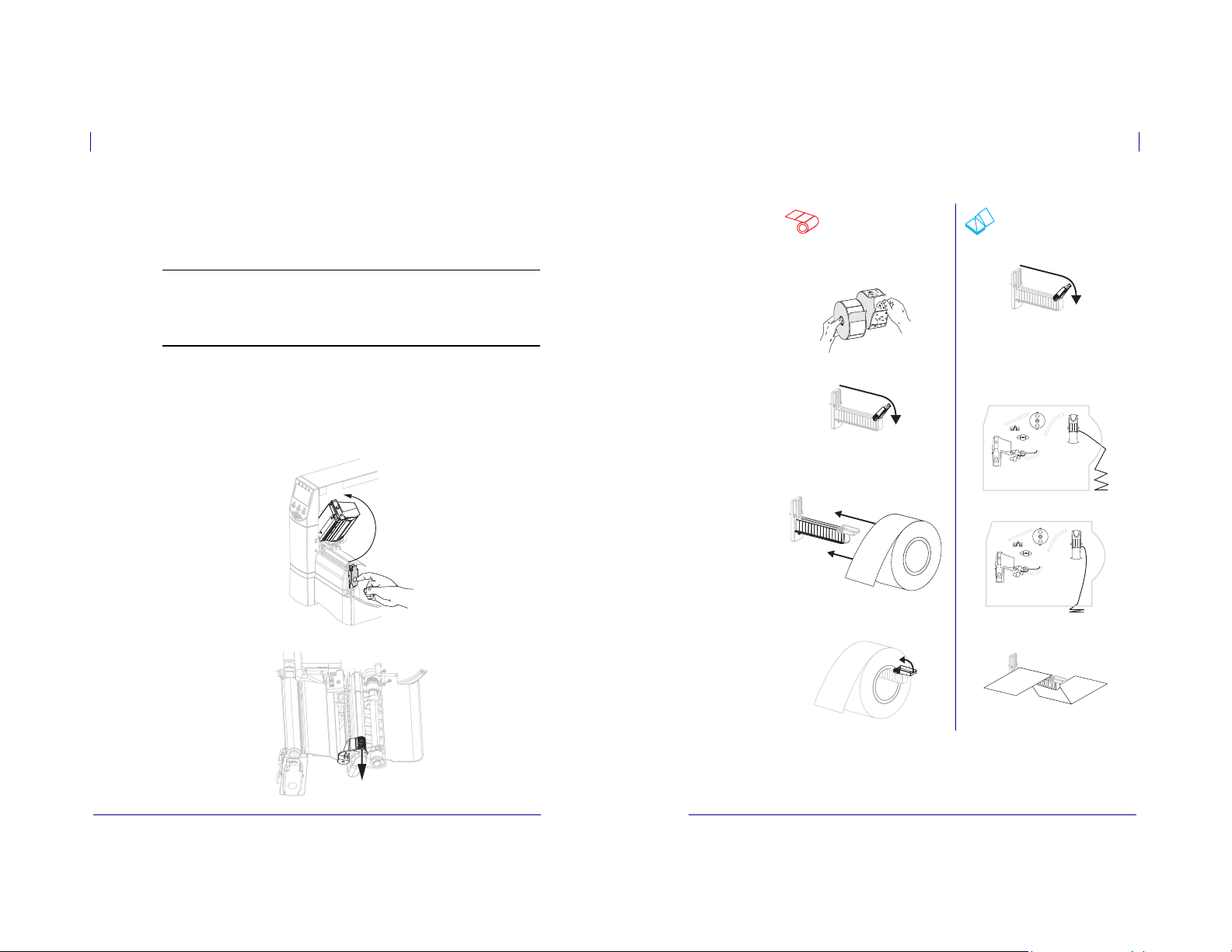
To operate the printer in Peel-Off mode, complete these steps:
1. Extend the media approximately 18 in. (500 mm) out of the printer.
2. Remove the exposed labels so that only the liner remains.
3. Push down the peel-off mechanism release lever to open the peel assembly.
4. Feed the liner over the tear-off/peel-off bar (1) and behind the peel assembly (2). Make
sure that the end of the liner falls outside of the printer.
1
2
5. Complete this step only if you want to use Peel-Off mode with liner take-up. Your printer
must have the Liner Take-Up option or the Rewind option installed. Follow the
instructions for your printer option.
Rewind Option Liner Take-Up Option
a. Feed the liner under the media
alignment roller (
1).
a. Slide the liner into the slot in the
liner take-up spindle (
1).
79695L-002 Rev. A ZM™ Series/RZ™ Series User Guide 5/12/08
1
1
5/12/08 ZM™ Series/RZ™ Series User Guide 79695L-002 Rev. A
Page 24

47
Operations
Load Media
Operations
Load Media
48
Rewind Option (Continued) Liner Take-Up Option (Continued)
b. Loosen the thumbscrew on the
rewind media guide.
c. Slide the rewind media guide all the
way out, and then fold it down.
d. Slide an empty core onto the rewind
spindle.
b. Push the liner back until it touches
the back plate of the liner take-up
spindle assembly.
c. Wrap the liner around the liner
take-up spindle and turn the spindle
counterclockwise to tighten the liner.
Rewind Option (Continued) Liner Take-Up Option (Continued)
e. Wrap the liner around the core and
turn the rewind spindle
counterclockwise to tighten the liner.
f. Fold up the rewind media guide, and
then slide it in until it touches the
liner.
g. Tighten the thumbscrew on the
rewind media guide.
(No additional steps for the liner take-up
option.)
79695L-002 Rev. A ZM™ Series/RZ™ Series User Guide 5/12/08
5/12/08 ZM™ Series/RZ™ Series User Guide 79695L-002 Rev. A
Page 25

49
Operations
Load Media
Operations
Load Media
50
6.
Caution • Use the peel release lever and your right hand to close the peel assembly.
Do not use your left hand to assist in closing. The top edge of the peel roller/assembly
could pinch your fingers.
Close the peel assembly using the peel-off mechanism release lever.
Slide in the media guide until it touches the outer edge of the media.
7.
8. Set the printer to Peel-Off mode. See Select Print Mode on page 73 for instructions.
9. Close the printhead assembly.
Additional Steps for Cutter or Delayed Cut Mode
After completing Beginning Steps for all Print Modes and Printer Options onpage 41,
continue with this section to operate the printer in Cutter or Delayed Cut mode.
To operate the printer in Cutter or Delayed Cut mode, complete these steps:
1.
Caution • The cutter blade is sharp. Do not touch or rub the blade with your fingers.
Feed the media through the cutter (1).
1
Slide in the media guide until it touches the outer edge of the media.
2.
10. If the printer is paused (the Pause light is on), press PAUSE to enable printing. Peeling and
liner take-up (if used) begin automatically.
79695L-002 Rev. A ZM™ Series/RZ™ Series User Guide 5/12/08
3. Set the printer to Cutter or Delayed Cut mode. See Select Print Mode on page 73 for
instructions.
5/12/08 ZM™ Series/RZ™ Series User Guide 79695L-002 Rev. A
Page 26

51
Operations
Load Media
Operations
Load Media
52
4. Close the printhead assembly.
5. If the printer is paused (the Pause light is on), press PAUSE to enable printing. Cutting
begins automatically.
Additional Steps for Rewind Mode
After completing Beginning Steps for all Print Modes and Printer Options onpage 41,
continue with this section to operate the printer in Rewind mode. For additional procedures
related to the rewind option, see Routine Maintenance for the Rewind Option on page 106.
To operate the printer in Rewind mode, complete these steps:
1. Pull approximately 18 in. (500 mm) of media through the front of the printer.
2. Feed the media over the peel assembly (1).
1
3. Feed the media under the media alignment roller (1).
1
4. Loosen the thumbscrew on the rewind media guide.
5. Slide the rewind media guide all the way out, and then fold it down.
79695L-002 Rev. A ZM™ Series/RZ™ Series User Guide 5/12/08
5/12/08 ZM™ Series/RZ™ Series User Guide 79695L-002 Rev. A
Page 27

53
Operations
Load Media
Operations
Load Media
54
6. Slide an empty core onto the rewind spindle.
7. Wrap the media around the core and turn the rewind spindle counterclockwise to tighten
the media. Ensure that the edge of the media is flush against the backplate of the rewind
spindle.
8. Fold up the rewind media guide, and then slide it in until it touches the media.
9. Tighten the thumbscrew on the rewind media guide.
10. Slide in the media guide until it touches the outer edge of the media.
11. Set the printer to Rewind mode. See Select Print Mode on page 73 for instructions.
12. Close the printhead assembly.
13. If the printer is paused (the Pause light is on), press PAUSE to enable printing. Rewinding
begins automatically.
79695L-002 Rev. A ZM™ Series/RZ™ Series User Guide 5/12/08
5/12/08 ZM™ Series/RZ™ Series User Guide 79695L-002 Rev. A
Page 28

Operations
Load Ribbon
55
56
Operations
Load Ribbon
Load Ribbon
Always use ribbon that is wider than the media to protect the printhead from wear. For direct
thermal printing, do not load ribbon in the printer.
The standard Thermal Transfer option (black ribbon spindle) uses ribbon coated on the
outside, and the alternate Thermal Transfer option (gray ribbon spindle) uses ribbon coated on
the inside. To avoid damaging your printer, follow the directions for the Thermal Transfer
option installed in your printer.
Figure 8 shows the ribbon paths for ribbon coated on the outside and ribbon coated on the
inside. The coated surfaces of the ribbon are shown in gray when they are visible. To
determine which side of a ribbon is printed, see Coated Side of Ribbon onpage 35.
Figure 8 • Ribbon Path
Ribbon Coated Outside
(black ribbon spindle)
Caution • While performing any tasks near an open printhead, remove all rings, watches,
hanging necklaces, identification badges, or other metallic objects that could touch the
printhead. You are not required to turn off the printer power when working near an open
printhead, but Zebra recommends it as a precaution. If you turn off the power, you will lose
all temporary settings, such as label formats, and you must reload them before you resume
printing.
To load ribbon, complete these steps:
1. Set the ribbon supply spindle for normal or low tension.
• To place the ribbon supply spindle in the normal position, firmly pull out the spindle
end cap until it extends and clicks in place, as shown in Figure 9. Use this setting for
most applications.
• To place the ribbon supply spindle in the low-tension position, firmly push in the end
Ribbon Coated Inside
(gray ribbon spindle)
cap until it retracts and clicks in place, as shown in Figure9. Use this setting when
using a narrow ribbon or if normal tension hampers ribbon movement.
Figure 9 • Ribbon Spindle—Normal and Low Tension
1 2
1
2
3
4
5
1
Normal Position (Spindle End Cap Extended)
2
3
4
5
2. Press the printhead release latch to open the printhead assembly. Lift the printhead until it
latches open.
1
Low-Tension Position (Spindle End Cap Retracted)
2
Tension blade
1
Ribbon take-up spindle
2
Ribbon supply spindle
3
Printhead assembly
4
Printhead release latch
5
5/12/08 ZM™ Series/RZ™ Series User Guide 79695L-002 Rev. A
79695L-002 Rev. A ZM™ Series/RZ™ Series User Guide 5/12/08
Page 29

Operations
Load Ribbon
57
58
Operations
Load Ribbon
3. Insert the ribbon into the printer. In this step, follow the instructions for the Thermal
Transfer option installed in your printer.
Ribbon Coated Outside
(black ribbon spindle)
a. Hold the ribbon with the loose end unrolling
clockwise.
b. Place the roll of ribbon on the ribbon supply
spindle (
1) and push it all the way back.
1 1
c. Pull the end of the ribbon under the printhead
1) and out the front of the printer.
assembly (
Extend the ribbon approximately 24 in.
(610 mm) out of the printer.
Ribbon Coated Inside
(gray ribbon spindle)
a. Hold the ribbon with the loose end unrolling
counterclockwise.
b. Place the roll of ribbon on the ribbon supply
spindle (
1) and push it all the way back.
c. Pull the end of the ribbon under the printhead
1) and out the front of the printer.
assembly (
Extend the ribbon approximately 24 in.
(610 mm) out of the printer.
4. Close the printhead assembly.
5. Wind the ribbon clockwise onto the ribbon take-up spindle (1).
Ribbon Coated Outside
(black ribbon spindle)
Ribbon Coated Inside
(gray ribbon spindle)
1
1
1 1
5/12/08 ZM™ Series/RZ™ Series User Guide 79695L-002 Rev. A
79695L-002 Rev. A ZM™ Series/RZ™ Series User Guide 5/12/08
Page 30

Operations
MEDIA POW ER UP
HEAD CLOS E
Load Ribbon
59
Operations
Calibrate the Printer
60
Remove Used Ribbon
To remove used ribbon, complete these steps:
1.
Caution • Do not cut the ribbon directly on the ribbon take-up spindle. Doing so may
damage the spindle.
If the ribbon has not run out, cut or break it before the ribbon take-up spindle (1).
To loosen the ribbon, squeeze it against the ribbon take-up spindle tension blades(1). At
2.
the same time, turn the ribbon take-up spindle release knob counterclockwise (2).
The tension blades collapse into the ribbon take-up spindle, loosening the ribbon.
3. Slide the used ribbon off of the ribbon take-up spindle and discard.
1
1
2
Calibrate the Printer
Auto Calibration
By default, the printer automatically calibrates on power up or when the printhead is closed.
During auto calibration, the printer determines the label length and sensor settings.
The results of the auto calibration are stored in the printer’s memory and are retained even if
printer power is removed. These parameters remain in effect until the next calibration is
performed.
Note • If the control panel settings for
LENGTH, NO MOTION, or FEED, the printer starts printing without auto calibrating. See
Select Media Power-Up Option on page 90 or Select Head Close Option on page 90.
Manual Calibration
Perform a media and ribbon sensor calibration to reset the sensitivity of the sensors so the
media and ribbon are detected more accurately. If you change the type of ribbon or media,
your printer may operate better if you perform this calibration.
For instructions, refer to Calibrate Media and Ribbon Sensor Sensitivity on page 84.
or
are set to
5/12/08 ZM™ Series/RZ™ Series User Guide 79695L-002 Rev. A
5/12/08 ZM™ Series/RZ™ Series User Guide 79695L-002 Rev. A
Page 31

Adjust Printhead Pressure
Operations
61
Operations
62
Adjust Printhead Pressure
Adjust Printhead Pressure
You may need to adjust printhead pressure if printing is too light on one side, if you use thick
media, or if the media drifts from side to side during printing.
See Figure 10. The ZM400 pressure adjustment dials have four possible settings designated by
blocks of increasing size embossed on the print mechanism. The smallest block (fully
counterclockwise) is considered position 1, and the largest block (fully clockwise) is
considered position 4. The ZM600 dials have seven settings instead of four.
Figure 10 • Printhead Pressure Adjustment Dials
1
1
2
To set printhead pressure, complete these steps:
1. Use Table 10 or Table 11 to select the initial dial settings for your media, depending on
which printer you have.
Table 10 • ZM400 Printhead Pressure
Media Width
1 in. (25.4 mm)
2 in. (51 mm)
3 in. (76 mm)
3.5 in. and up (89 mm and up)
2
Outside dial
Inside dial
Inside Dial Outside Dial
31
41
32
33
Table 11 • ZM600 Printhead Pressure
Media Width
Inside Dial Outside Dial
2 in. (50 mm) 6 1
3 in. (75 mm) 6 2
4 in. (100 mm) 7 3
5 in. (125 mm) 7 4
5.5 in. and up (140 mm and up) 6 6
2. If necessary, adjust the pressure adjustment dials as follows:
If the media... Then...
Requires higher pressure to
print well
Shifts left while printing Increase the outside dial setting one position, or
Shifts right while printing Increase the inside dial setting one position, or
Prints too lightly on the left side
of the label.
Prints too lightly on the right
side of the label.
Increase both dials one position.
decrease the inside dial setting one position.
decrease the outside dial setting one position.
Increase the inside dial setting one position.
Increase the outside dial setting one position.
5/12/08 ZM™ Series/RZ™ Series User Guide 79695L-002 Rev. A
79695L-002 Rev. A ZM™ Series/RZ™ Series User Guide 5/12/08
Page 32

4
Configuration
PRINT ER R EADY
This section describes the control panel parameters that are used to configure the printer for
operation.
Contents
Setup Mode . . . . . . . . . . . . . . . . . . . . . . . . . . . . . . . . . . . . . . . . . . . . . . . . . . . . . . . . . . . 64
Enter Setup Mode . . . . . . . . . . . . . . . . . . . . . . . . . . . . . . . . . . . . . . . . . . . . . . . . . . . . 64
Exit Setup Mode. . . . . . . . . . . . . . . . . . . . . . . . . . . . . . . . . . . . . . . . . . . . . . . . . . . . . . 65
Change Password-Protected Parameters . . . . . . . . . . . . . . . . . . . . . . . . . . . . . . . . . . . . 66
Default Password Value. . . . . . . . . . . . . . . . . . . . . . . . . . . . . . . . . . . . . . . . . . . . . . . . 66
Disable the Password Protection Feature . . . . . . . . . . . . . . . . . . . . . . . . . . . . . . . . . . 66
Print a Configuration Label. . . . . . . . . . . . . . . . . . . . . . . . . . . . . . . . . . . . . . . . . . . . . . . . 67
Print a Network Configuration Label . . . . . . . . . . . . . . . . . . . . . . . . . . . . . . . . . . . . . . . . 68
Control Panel Parameters . . . . . . . . . . . . . . . . . . . . . . . . . . . . . . . . . . . . . . . . . . . . . . . . 69
How to View or Modify Parameters . . . . . . . . . . . . . . . . . . . . . . . . . . . . . . . . . . . . . . . 69
Additional Parameters . . . . . . . . . . . . . . . . . . . . . . . . . . . . . . . . . . . . . . . . . . . . . . . . . 69
Standard Printer Parameters. . . . . . . . . . . . . . . . . . . . . . . . . . . . . . . . . . . . . . . . . . . . 70
Setup Mode
After you have installed the media and ribbon and the Power-On Self Test (POST) is complete,
the control panel displays
application using the control panel display and the buttons directly below it. If it becomes
necessary to restore the initial printer defaults, see FEED and PAUSE Self Test onpage129.
Important • Certain printing conditions may require that you adjust printing parameters,
such as print speed, darkness, or print mode. These conditions include (but are not
limited to):
• printing at high speeds
• peeling the media
• the use of extremely thin, small, synthetic, or coated labels
Because these and other factors affect print quality, run tests todetermine the best
combination of printer settings and media for your application. A poor match may limit print
quality or print rate, or the printer may not function properly in the desired print mode.
Enter Setup Mode
To enter Setup Mode, complete these steps:
1. Press SETUP/EXIT.
2. Press PLUS (+) or MINUS (–) to scroll through the parameters.
3. Press SELECT to select and deselect the parameters.
Configuration
Setup Mode
. You may now set printer parameters for your
64
5/12/08 ZM™ Series/RZ™ Series User Guide 79695L-002 Rev. A
5/12/08 ZM™ Series/RZ™ Series User Guide 79695L-002 Rev. A
Page 33

65
SAVE CHA NGES
PRINT ER R EADY
PERMA NENT
TEMPO RARY
CANCE L
LOAD DEFA ULTS
LOAD LAST SAVE
DEFAU LT N ET
ENTER PAS SWORD
Configuration
Setup Mode
Change Password-Protected Parameters
Configuration
66
Exit Setup Mode
To leave Setup mode, complete these steps:
1. Press SETUP/EXIT.
The LCD displays
2. Press PLUS (+) or MINUS (-) to display the save options:
LCD Description
Stores values in the printer even when power is turned off.
3. Press SETUP/EXIT to select the displayed choice.
When the configuration and calibration sequence is done,
Saves the changes until power is turned off.
Cancels all changes made since you entered Setup mode,
except for changes made to the darkness and tear-off settings,
which go into effect as soon as they are made.
Restores all parameters other than the network settings back to
the factory defaults. Use care when loading defaults because
you will need to reload all settings that you changed manually.
Loads values from the last permanent save.
Restores the wired and wireless network settings back to
factory defaults.
.
Note • Loading factory defaults causes the printer to
auto-calibrate.
displays.
Change Password-Protected Parameters
Certain parameters, including the communication parameters, are password-protected by
factory default.
Caution • Do not change password-protected parameters unless you have a complete
understanding of the parameters’ functions. If the parameters are set incorrectly, the printer
may function unpredictably.
The first time that you attempt to change a password-protected parameter, the printer displays
numeric password. After you have entered the password correctly, you do not have to enter it
again unless you leave Setup mode by pressing
To enter a password for a password-protected parameter, complete
these steps:
1. At the password prompt, use MINUS (-) to change the selected digit position.
2. When you have selected the digit that you wish to change, use PLUS (+) to increase the
selected digit value. Repeat these two steps for each digit of the password.
3. After entering the password, press SELECT.
The parameter you selected to change is displayed. If the password was entered correctly,
you can change the value.
Default Password Value
The default password value is 1234. The password can be changed using the Zebra
Programming Language (ZPL) command
pages (ZebraNet
Disable the Password Protection Feature
You can disable the password protection feature so that it no longer prompts you for a
password by setting the password to 0000 via the
password-protection feature, send the ZPL command
1 to 9999.
. Before you can change the parameter, you must enter the four-digit
SETUP/EXIT or by turning off (O) the printer.
®
10/100 Print Server, or Wireless Plus Print Server required).
^KP (Define Password) or using the printer’s web
^KP ZPL command. To re-enable the
^KPx, where x can be any number from
79695L-002 Rev. A ZM™ Series/RZ™ Series User Guide 5/12/08
5/12/08 ZM™ Series/RZ™ Series User Guide 79695L-002 Rev. A
Page 34

Configuration
LIST SET UP
LIST NET WORK
Print a Configuration Label
67
Print a Network Configuration Label
Configuration
68
Print a Configuration Label
A configuration label lists the printer settings that are stored in configuration memory. After
you load the media, print a configuration label as a record of your printer’s current settings.
Keep the label to use when troubleshooting printing problems.
To print a configuration label, complete these steps:
1. On the control panel, press SETUP/EXIT.
2. Press PLUS (+) or MINUS (-) to scroll through the parameters until you reach
3. Press SELECT to select the parameter.
4. Press PLUS (+) to confirm printing.
A configuration label prints (Figure 11).
.
Figure 11 • Configuration Label
Print a Network Configuration Label
If you are using a print server, you can print a network configuration label after the printer is
connected to the network.
To print a network configuration label, complete these steps:
1. On the control panel, press SETUP/EXIT.
2. Press PLUS (+) or MINUS (-) to scroll through the parameters until you reach
3. Press SELECT to select the parameter.
4. Press PLUS (+) to confirm printing.
A network configuration label prints (Figure 12). An asterisk designates whether the
wired or wireless print server is active. If no wireless print server is installed, the wireless
portion of the label does not print.
Figure 12 • Network Configuration Label (With a Wireless Print Server Installed)
.
5/12/08 ZM™ Series/RZ™ Series User Guide 79695L-002 Rev. A
5/12/08 ZM™ Series/RZ™ Series User Guide 79695L-002 Rev. A
Page 35

Configuration
Control Panel Parameters
69
Configuration
70
Control Panel Parameters
Control Panel Parameters
Use the LCD on the control panel to view and adjust printer settings.
How to View or Modify Parameters
While viewing parameters, press PLUS (+) to continue to the next parameter, or press
MINUS (-) to return to the previous parameter in the cycle. Press SELECT when you want to
modify a parameter or view its options. When a parameter is changed, an asterisk (*) appears
in the upper left corner of the display to indicate that the value is different from the one
currently active in the printer.
Note • Your label preparation software or the printer driver may override adjustments made
through the control panel. Refer to the software or driver documentation for more
information.
Additional Parameters
Additional parameters appear in the following situations.
• When a wired print server is installed in the printer. For more information, refer to the
ZebraNet 10/100 Print Server User and Reference Guide
• When a wireless print server is installed in the printer. Refer to the ZebraNet Wireless
Print Server and Wireless Plus Print Server User Guide.
• When a Radio Frequency Identification (RFID) reader is installed. Refer to the RFID
Programming Guide for more information.
Copies of these manuals are available at http://www.zebra.com/manuals or on the userCD that
came with your printer.
Standard Printer Parameters
Table 12 shows parameters in the order in which they are displayed when you press PLUS (+)
after entering Setup mode.
Table 12 • Printer Parameters (Page 1 of 26)
Parameter Action/Explanation
ZPL, XML, APL-D, APL-I
EPL only
Adjust Print Darkness/Density
Darkness (burn duration) settings depend on a variety of factors, including
ribbon type, media type, and the condition of the printhead. Yo u may adjust
the darkness for consistent high-quality printing.
If printing is too light or if there are voids in printed areas, increase the
darkness. If printing is too dark or if there is spreading or bleeding of
printed areas, decrease the darkness.
The FEED Self T est onpage 126 can be used to determine the best darkness
setting. Y ou may want to adjust darkness while performing the PAUSE Se lf
Test on page 125. Because the darkness setting takes effect immediately,
you can see the results on labels that are currently printing. Darkness
settings also may be changed by the driver or software settings.
Default Value (ZPL, XML, APL-D, APL-I): +10
Range (ZPL, XML, APL-D, APL-I): 00 to +30
Default Value (EPL): +7
Range (EPL): 00 to +15
To change the value shown:
1. Press SELECT to select the parameter.
2. Press
3. Press
4. Press
Important • Set the darkness to the lowest setting that provides
good print quality. If the darkness is set too high, the ink may
smear, the ribbon may burn through, or the printhead may wear
prematurely.
PLUS (+) to increase darkness.
MINUS (-) to decrease darkness.
SELECT to accept any changes and deselect the parameter.
5/12/08 ZM™ Series/RZ™ Series User Guide 79695L-002 Rev. A
79695L-002 Rev. A ZM™ Series/RZ™ Series User Guide 5/12/08
Page 36

Configuration
Control Panel Parameters
71
Configuration
72
Control Panel Parameters
Parameter
Table 12 • Printer Parameters (Page 2 of 26)
Action/Explanation
Adjust Print Speed
Adjusts the speed for printing a label (given in inches per second). Slower
print speeds typically yield better print quality. Print speed changes take
effect upon exiting Setup mode.
Default Value (ZPL, XML, APL-I, EPL): 2 IPS
Default Value (APL-D): 6 IPS
Range:
• 200 dpi: 2 to 10 IPS
• 300 dpi: 2 to 8 IPS
• 600 dpi: 1 to 4 IPS
To change the value shown:
1. Press SELECT to select the parameter.
PLUS (+) to increase the value.
2. Press
3. Press
MINUS (-) to decrease the value.
SELECT to accept any changes and deselect the parameter.
4. Press
Parameter
Table 12 • Printer Parameters (Page 3 of 26)
Action/Explanation
Adjust the Tear-Off Position
This parameter establishes the position of the media over the
tear-off/peel-off bar after printing.
See Figure 13. Higher numbers move the media out (the tear line moves
closer to the leading edge of the next label), and lower numbers move the
media in (the tear line moves closer to the edge of the label just printed).
Figure 13 • Tear-Off Position Adjustment
1
Media direction
1
Factory-set tear line location at position 00
2
2
Default Value (ZPL, EPL, APL-I): 0
Range (ZPL, EPL, APL-I): -120 to +120
Default Value (APL-D): +128i
Range (APL-D): +00i to +999i (inches), 0m to 2537m (metric)
To change the value shown:
1. Press SELECT to select the parameter.
PLUS (+) to increase the value. Each press adjusts the tear-off
2. Press
position by four dot rows.
MINUS (-) to decrease the value. Each press adjusts the tear-off
3. Press
position by four dot rows.
SELECT to accept any changes and deselect the parameter.
4. Press
5/12/08 ZM™ Series/RZ™ Series User Guide 79695L-002 Rev. A
79695L-002 Rev. A ZM™ Series/RZ™ Series User Guide 5/12/08
Page 37

Configuration
Control Panel Parameters
73
Configuration
74
Control Panel Parameters
Parameter
APL-D only
APL-D only
APL-D only
Table 12 • Printer Parameters (Page 4 of 26)
Action/Explanation
Select Print Mode
This parameter tells the printer how printed labels will be removed. Make
sure that you select a print mode that is compatible with your printer and
printer options. For information about how the print modes work with
different printer options, see Print Modes and Printer Options on page 38.
Default Value: TEAR-OFF
Selections: TEAR-OFF, PEEL-OFF, CUTTER, DELAYED CUT,
LINERLESS-P, LINERLESS-R, LINERLESS-T, REWIND
Note • The linerless selections apply only to printers that have the
Linerless option.
To change the value shown:
1. Press SELECT to select the parameter.
PLUS (+) or MINUS (-) to scroll through the options.
2. Press
SELECT to accept any changes and deselect the parameter.
3. Press
Set APL-D Compatibility Mode
Sets compatibility with DPL printers.
Default Value: OFF
Selections: ON, OFF
To change the value shown:
1. Press SELECT to select the parameter.
PLUS (+) or MINUS (-) to scroll through the options.
2. Press
SELECT to accept any changes and deselect the parameter.
3. Press
Set APL-D Control Codes
Default Value: STANDARD
Selections: STANDARD, MAINFRAME
To change the value shown:
1. Press SELECT to select the parameter.
PLUS (+) or MINUS (-) to scroll through the options.
2. Press
SELECT to accept any changes and deselect the parameter.
3. Press
Set Module A Storage Device for APL-D
Default Value: NONE
Selections: NONE, RAM 1, RAM 2, FLASH 1, FLASH 2
To change the value shown:
1. Press SELECT to select the parameter.
PLUS (+) or MINUS (-) to scroll through the options.
2. Press
SELECT to accept any changes and deselect the parameter.
3. Press
Parameter
APL-D only
APL-I only
Table 12 • Printer Parameters (Page 5 of 26)
Action/Explanation
Set Module B Storage Device for APL-D
Default Value: NONE
Selections: NONE, RAM 1, RAM 2, FLASH 1, FLASH 2
To change the value shown:
1. Press SELECT to select the parameter.
PLUS (+) or MINUS (-) to scroll through the options.
2. Press
SELECT to accept any changes and deselect the parameter.
3. Press
Set Printer Resolution for APL-I
Sets the dot size for backward compatibility with some older APL-I
printers.
Default Value: 5 MIL
Selections: 5 MIL, 10 MIL, 15 MIL
To change the value shown:
1. Press SELECT to select the parameter.
PLUS (+) or MINUS (-) to scroll through the options.
2. Press
SELECT to accept any changes and deselect the parameter.
3. Press
Set Media Type
This parameter tells the printer the type of media that you are using (see
Types of Media onpage 33 for more information). Selecting continuous
media requires that you include a label length instruction in your label
^LLxxxx if you are using ZPL or ZPL II).
format (
When non-continuous media is selected, the printer feeds media to
calculate label length (the distance between two recognized registration
points of the inter-label gap, webbing, or alignment notch or hole).
Default Value: GAP/NOTCH
Selections: GAP/NOTCH, MARK, CONTINUOUS
To change the value shown:
1. Press SELECT to select the parameter.
PLUS (+) or MINUS (-) to scroll through the options.
2. Press
SELECT to accept any changes and deselect the parameter.
3. Press
5/12/08 ZM™ Series/RZ™ Series User Guide 79695L-002 Rev. A
79695L-002 Rev. A ZM™ Series/RZ™ Series User Guide 5/12/08
Page 38

Configuration
Control Panel Parameters
75
Configuration
76
Control Panel Parameters
Parameter
Table 12 • Printer Parameters (Page 6 of 26)
Action/Explanation
Select Print Method
The print method parameter tells the printer the method of printing that you
want to use: direct thermal (no ribbon) or thermal transfer (using thermal
transfer media and ribbon).
Default Value: THERMAL TRANSFER
Selections: THERMAL TRANSFER, DIRECT THERMAL
To change the value shown:
1. Press SELECT to select the parameter.
PLUS (+) or MINUS (-) to scroll through the options.
2. Press
SELECT to accept any changes and deselect the parameter.
3. Press
Set Print Width
This parameter specifies the printable area across the width of the label.
Table 13 shows the ranges and default values for print width, which are
based on the printer model and the printhead resolution.
Table 13 • Print Width Ranges and Maximum Values
Printhead
Resolution
200 dpi
300 dpi
600 dpi
ZM400 ZM600
Default Value: 832
Range: 2 to 832 dots
Default Value: 1248
Range: 2 to 1248 dots
Default Value: 2496
Printer
Default Value: 1344
Range: 2 to 1344 dots
Default Value: 1984
Range: 2 to 1984 dots
N/A
Range: 2 to 2496 dots
Note • Setting the width too narrow can result in portions of a label
format not being printed on the media. Setting the width too wide
wastes formatting memory and can cause printing off of the label
and on the platen roller. This setting can affect the horizontal
position of the label format if the image was inverted using the
^POI ZPL II command.
To change the value shown:
1. Press SELECT to select the parameter.
2. Press
PLUS (+) or MINUS (-) to change the value shown.
SELECT to accept any changes and deselect the parameter.
3. Press
Parameter
ZPL, XML, EPL, APL-I
APL-D only
Table 12 • Printer Parameters (Page 7 of 26)
Action/Explanation
Set Maximum Label Length
This parameter is used during the media portion of the calibration process.
Always set maximum label length to a value that is at least 1.0 in.
(25.4 mm) greater than the actual label length (Figure 14). If the value is set
to a smaller value than the label length, the printer assumes that continuous
media is loaded, and the printer cannot calibrate.
For example, if the label length is 5.0 inches (126 mm) including the
interlabel gap, set the parameter for 6.0 inches (152 mm). If the label length
is 7.5 inches (190 mm), set the parameter for 9.0 inches (229 mm).
Figure 14 • Label Length
2
}
1
Label length (including interlabel gap)
1
Interlabel gap
2
Set maximum label length to approximately
3
this value
Default Value (ZPL, XML, EPL, APL-I): 39.0 inches (988 mm)
Selections: Values are adjustable in one-inch (25.4 mm) increments
Default Value (APL-D): 1200i
Range: 1200i to
To change the value shown:
1. Press SELECT to select the parameter.
PLUS (+) or MINUS (-) to change the value shown.
2. Press
3. Press
SELECT to accept any changes and deselect the parameter.
3
5/12/08 ZM™ Series/RZ™ Series User Guide 79695L-002 Rev. A
79695L-002 Rev. A ZM™ Series/RZ™ Series User Guide 5/12/08
Page 39

Configuration
EARLY WAR NING MAIN TENANCE
OFF
WARNI NG C LEAN
PRINT HEAD
YES
NO
WARNI NG R EPLACE
HEAD
YES
NO
Control Panel Parameters
77
Configuration
78
Control Panel Parameters
Parameter
Table 12 • Printer Parameters (Page 8 of 26)
Action/Explanation
Set Early Warning for Maintenance
When this feature is enabled, the printer provides warnings when the
printhead needs to be cleaned.
Default Value: MAINT. OFF
Selections: MAINT. OFF, MAINTENANCE ON
To change the Early Warning settings:
1. Press SELECT to select the parameter.
2. When the LCD displays
PLUS (+) or MINUS (-) to toggle between
prompted for a password, enter your password using the instructions in
Change Password-Protected Parameters onpage 66.)
3. Exit Setup mode and save changes to enable additional parameters
related to the early warning system.
4. Enter Setup mode again and go to the following parameters to enter the
printhead cleaning interval and the printhead life.
SELECT to accept any changes and deselect the parameter.
5. Press
Set Printhead Cleaning Interval for Early Warning
This parameter appears only when Early Warning for Maintenance is
enabled. This value should correspond to the length of the media or ribbon
roll that you are using.
and ON. (If you are
Default Value: 450 M/1476 FT
Selections: 100 M/328 FT to 450 M/1476 FT in 50 M increments
To change the value shown:
1. Press SELECT to select the parameter.
PLUS (+) or MINUS (-) to set the printhead cleaning interval to
2. Press
the desired number of inches of media or ribbon.
When the printhead reaches the set length,
printer generates an alert.
3. Press
appears on the LCD. If the alert function is enabled, the
SELECT to accept any changes and deselect the parameter.
Reset Printhead Cleaning Counter for Early Warning
This parameter appears only when Early Warning for Maintenance is
enabled.
To reset the printhead cleaning counter:
1. Press SELECT to select the parameter.
2. Did you clean the printhead?
• If you cleaned the printhead, press
• If you did not clean the printhead, press
3. Press
SELECT to accept any changes and deselect the parameter.
PLUS (+) to select
MINUS (-) to select
Table 12 • Printer Parameters (Page 9 of 26)
Parameter
Action/Explanation
Set Printhead Life for Early Warning
This parameter appears only when Early Warning for Maintenance is
enabled. Set this value to the number of inches of media that the printhead
is expected to print.
Default Value: 1,000,000 inches
Range: 100 to 1,000,000 inches
To change the value shown:
, press
1. Press SELECT to select the parameter.
MINUS (-) to move the cursor.
2. Press
PLUS (+) to increase the value of the digit.
3. Press
When the printhead reaches the set length,
appears on the LCD. If the alert function is enabled, the printer
generates an alert.
SELECT to accept any changes and deselect the parameter.
4. Press
Reset Printhead Life Counter for Early Warning
This parameter appears only when Early Warning for Maintenance is
enabled.
To reset the printhead life counter:
1. Press SELECT to select the parameter.
2. Did you replace the printhead?
• If you replaced the printhead, press
PLUS (+) to select
• If you did not replace the printhead, press
SELECT to accept any changes and deselect the parameter.
3. Press
MINUS (-) to select
.
.
View Non-Resettable Counter
This parameter displays the total length of media that the printer has
printed. You can use ZPL commands to change the unit of measure for this
counter. For the commands, refer to the ZPL Programming Guide.
View User-Controlled Counter 1
This parameter displays the total length of media that the printer has printed
since this parameter was last reset. You can use ZPL commands to change
the unit of measure and reset this counter. For the commands, refer to the
ZPL Programming Guide.
View User-Controlled Counter 2
.
.
This parameter displays the total length of media that the printer has printed
since this parameter was last reset. You can use ZPL commands to change
the unit of measure and reset this counter. For the commands, refer to the
ZPL Programming Guide.
5/12/08 ZM™ Series/RZ™ Series User Guide 79695L-002 Rev. A
79695L-002 Rev. A ZM™ Series/RZ™ Series User Guide 5/12/08
Page 40

Configuration
PRINT
PRINT
PRINT
PRINT
PRINT
PRINT
PRINT
Control Panel Parameters
79
Configuration
80
Control Panel Parameters
Table 12 • Printer Parameters (Page 10 of 26)
Parameter
Action/Explanation
Print Counter Readings
Prints a label that lists the odometer readings for the following:
• the non-resettable counter
• the two user-controlled counters
• the Early Warning for Maintenance counters, which indicate when the
printhead was last cleaned and the printhead life
If the Early Warning for Maintenance feature is disabled, the counters
related to it do not print.
To print a list of the odometer readings:
1. Press SELECT to select the parameter.
2. Press
PLUS (+) to print the odometer readings.
SELECT to deselect the parameter.
3. Press
List Fonts
This option prints a label that lists the available fonts in the printer,
including standard printer fonts plus any optional fonts. Fonts may be
stored in RAM or Flash memory.
To print a list of the available fonts:
1. Press SELECT to select the parameter.
PLUS (+) to select
2. Press
SELECT to deselect the parameter.
3. Press
ZPL and XML only List Bar Codes
This option prints a label that lists the available bar codes in the printer. Bar
codes may be stored in RAM or Flash memory.
To print a list of the available bar codes:
1. Press SELECT to select the parameter.
PLUS (+) to select
2. Press
SELECT to deselect the parameter.
3. Press
List Images
This option prints a label that lists the available images stored in the
printer’s RAM, Flash memory, or optional memory card.
To print a list of the available images:
1. Press SELECT to select the parameter.
PLUS (+) to select
2. Press
SELECT to deselect the parameter.
3. Press
Table 12 • Printer Parameters (Page 11 of 26)
Parameter
Action/Explanation
List Formats
This option prints a label that lists the available formats stored in the
printer’s RAM, Flash memory, or optional memory card.
To print a list of the available formats:
1. Press SELECT to select the parameter.
ZPL, XML, EPL, APL-D
PLUS (+) to select
2. Press
3. Press
SELECT to deselect the parameter.
List Setup
This option prints a configuration label (see Figure 11 onpage 67), which
lists the current printer configuration.
To print a configuration label:
.
1. Press SELECT to select the parameter.
PLUS (+) to select
2. Press
3. Press
SELECT to deselect the parameter.
.
APL-I only
.
APL-I only Print Software Configuration Label
A software configuration label lists pages, formats, and bar codes that are
defined for the printer. Other printer settings also are included.
To print this label:
.
1. Press SELECT to select the parameter.
PLUS (+) to select
2. Press
SELECT to deselect the parameter.
3. Press
.
APL-I only Print Hardware Configuration Label
A hardware configuration label lists the memory options, printer metrics,
and printhead information.
To print this label:
.
1. Press SELECT to select the parameter.
2. Press
PLUS (+) to select
SELECT to deselect the parameter.
3. Press
.
5/12/08 ZM™ Series/RZ™ Series User Guide 79695L-002 Rev. A
79695L-002 Rev. A ZM™ Series/RZ™ Series User Guide 5/12/08
Page 41

Configuration
PRINT
PRINT
PRINT
PRINT
A:
ARE Y OU S URE?
NO
FORMA T CA RD
YES
FORMA TTIN G CARD CO MPLE TED
Control Panel Parameters
81
Configuration
82
Control Panel Parameters
Table 12 • Printer Parameters (Page 12 of 26)
Parameter
Action/Explanation
APL-I only Print Quality Test Label
A print quality test label contains test bar codes and relevant printer
settings.
To print this label:
1. Press SELECT to select the parameter.
PLUS (+) to select
2. Press
3. Press
SELECT to deselect the parameter.
APL-I only Print Pitch Test Label
To print this label:
1. Press SELECT to select the parameter.
PLUS (+) to select
2. Press
SELECT to deselect the parameter.
3. Press
List Network Settings
This option prints a network configuration label (see Figure 12
on page 68), which lists the settings for any print server that is installed.
To print a network configuration label:
1. Press SELECT to select the parameter.
PLUS (+) to select
2. Press
SELECT to deselect the parameter.
3. Press
ZPL, XML, EPL List All
This option prints labels that list the available fonts, bar codes, images,
formats, and the current printer and network configurations.
To print labels for all settings:
1. Press SELECT to select the parameter.
PLUS (+) to select
2. Press
SELECT to deselect the parameter.
3. Press
APL-I only
Print Stored APL-I Page
Up to 20 pages can be stored and printed.
Selections: 0 through 19
Default Value: 0
To modify this parameter:
• To increase the value, press the up arrow.
• To decrease the value, press the down arrow.
Table 12 • Printer Parameters (Page 13 of 26)
Parameter
APL-I only
Action/Explanation
Print Stored APL-I Format
Up to 100 formats can be stored and printed.
Selections: 0 through 99
Default Value: 0
.
To modify this parameter:
• To increase the value, press the up arrow.
• To decrease the value, press the down arrow.
ZPL and XML only Format Memory Card
This option erases all previously stored information from the optional
.
64 MB flash chip on the Wireless Plus option board. This parameter
appears only when a Wireless Plus option board with the flash chip
populated is installed.
Caution • This option completely erases the flash chip.
To format a memory card:
1. Press SELECT to select the parameter.
PLUS (+) to select
2. Press
If your printer is set to require a password, you are prompted to enter
.
the password.
3. Enter the password. For instructions, see Change Password-Protected
Parameters on page 66.
.
4. Press the appropriate button again to select the desired card.
The display shows
.
5. Do you want to continue?
MINUS (-) to select
• Press
.
• Press
When initialization is complete, the control panel displays
Note • Depending on the amount of memory in the memory card,
initialization may take up to 5 minutes to complete.
SELECT to deselect the parameter.
6. Press
prompt.
PLUS (+) to select
to cancel the request and return to
and begin initialization.
.
5/12/08 ZM™ Series/RZ™ Series User Guide 79695L-002 Rev. A
79695L-002 Rev. A ZM™ Series/RZ™ Series User Guide 5/12/08
Page 42

Configuration
INITI ALIZ E FLASH?
YES
ARE Y OU S URE?
NO
INITI ALIZ E FLASH
YES
INITI ALIZ ING MEMOR Y CO MPLETED
LOAD BACK ING
REMOV E RI BBON
CALIB RATI NG PLEASE WAI T
RELOA D AL L
Control Panel Parameters
83
Configuration
84
Control Panel Parameters
Parameter
Table 12 • Printer Parameters (Page 14 of 26)
Action/Explanation
Initialize Flash Memory
This option erases all previously stored information from Flash memory.
Caution • This option completely erases the Flash memory.
To initialize Flash memory:
1. Press SELECT to select the parameter.
2. If prompted for a password, enter the printer password. For
instructions, see Change Password-Protected Parameters onpage 66.
The display shows
3. Press PLUS (+) to select
The display shows
.
.
4. Do you want to continue?
MINUS (-) to select
• Press
• Press
PLUS (+) to select
When initialization is complete, the control panel displays
5. Press
Print Sensor Profile
A sensor profile shows sensor settings compared to actual sensor readings.
This label (which will extend across several actual labels or tags) can be
used to troubleshoot printing problems. To interpret the results of the
sensor profile, see Sensor Profile onpage 131.
Note • Depending on the amount of free FLASH memory,
initialization may take up to 1 minute to complete.
SELECT to accept any changes and deselect the parameter.
to cancel the request and return to the
prompt.
and begin initialization.
.
To print a sensor profile:
1. Press SELECT to select the parameter.
PLUS (+) to start this standard calibration procedure and print a
2. Press
media sensor profile.
3. If the sensitivity of the sensors must be adjusted, perform Calibrate
Media and Ribbon Sensor Sensitivity on page 84.
SELECT to accept any changes and deselect the parameter.
4. Press
Parameter
Table 12 • Printer Parameters (Page 15 of 26)
Action/Explanation
Calibrate Media and Ribbon Sensor Sensitivity
Use this procedure to adjust sensitivity of media and ribbon sensors.
Important • Follow this procedure exactly as presented. All of the
steps must be performed even if only one of the sensors requires
adjustment. You may press
to cancel the process.
To perform a media and ribbon sensor calibration:
MINUS (-) at any step in this procedure
1. Press SELECT to select the parameter.
PLUS (+) to start the calibration procedure.
2. Press
The
prompt displays.
3. Open the printhead.
4. Remove approximately 8 in. (203 mm) of labels from the backing, and
pull the media into the printer so that only the backing is between the
media sensors.
5. Leave the printhead open.
PLUS (+) to continue.
6. Press
The
prompt displays.
7. Remove the ribbon (if used).
8. Close the printhead.
PLUS (+) to continue.
9. Press
The message
The printer adjusts the scale (gain) of the signals that it receives from
the media and ribbon sensors based on the specific media and ribbon
combination being used. On the sensor profile, this essentially
corresponds to moving the peak of the graph up or down to optimize
the readings for your application.
When calibration is complete,
10. Open the printhead and pull the media forward until a label is
positioned under the media sensor.
displays.
displays.
11. Reload the ribbon (if used).
12. Close the printhead.
PLUS (+) to continue.
13. Press
The printer performs an auto-calibration. During this process, the
printer checks the readings for the media and ribbon based on the new
scale established, determines the label length, and determines the print
mode. To see the new readings on the new scale, print a sensor profile.
SELECT to accept any changes and deselect the parameter.
14. Press
5/12/08 ZM™ Series/RZ™ Series User Guide 79695L-002 Rev. A
79695L-002 Rev. A ZM™ Series/RZ™ Series User Guide 5/12/08
Page 43

Configuration
Control Panel Parameters
85
Configuration
86
Control Panel Parameters
Table 12 • Printer Parameters (Page 16 of 26)
Parameter
Action/Explanation
Set Parallel Communications
Select the communications port that matches the one being used by the host
computer.
Default Value: BIDIRECTIONAL
Selections: BIDIRECTIONAL, UNIDIRECTIONAL
To change the value shown:
1. Press SELECT to select the parameter.
PLUS (+) or MINUS (-) to scroll through the options.
2. Press
SELECT to accept any changes and deselect the parameter.
3. Press
ZPL and XML only Set Serial Communications
Select the communications port that matches the one being used by the host
computer. This setting applies only when the serial port is used.
Note • Select RS232 if you are using an external adapter to enable
RS422/485 operation.
Default Value: RS232
Selections: RS232, RS485 MULTIDROP
To change the value shown:
1. Press SELECT to select the parameter.
2. Press
PLUS (+) or MINUS (-) to scroll through the options.
SELECT to accept any changes and deselect the parameter.
3. Press
Set Baud
This setting applies only when the serial port is used. The baud setting of
the printer must match the baud setting of the host computer for accurate
communications to take place. Select the value that matches the one being
used by the host computer.
Default Value: 9600
Selections (ZPL, XML): 300, 600, 1200, 2400, 4800, 9600, 14400, 19200,
28800, 38400, 57600, 115200
Selections (EPL): 1200, 2400, 4800, 9600, 19200, 38400, 57600, 115200
To change the value shown:
1. Press SELECT to select the parameter.
2. Press
PLUS (+) or MINUS (-) to scroll through the options.
SELECT to accept any changes and deselect the parameter.
3. Press
Parameter
Table 12 • Printer Parameters (Page 17 of 26)
Action/Explanation
Set Data Bits
This setting applies only when the serial port is used. The data bits of the
printer must match the data bits of the host computer for accurate
communications to take place. Set the data bits to match the setting being
used by the host computer.
Default Value: 8BITS
Selections: 7BITS, 8BITS
To change the value shown:
1. Press SELECT to select the parameter.
PLUS (+) or MINUS (-) to toggle between the options.
2. Press
SELECT to accept any changes and deselect the parameter.
3. Press
Set Parity
This setting applies only when the serial port is used. The parity of the
printer must match the parity of the host computer for accurate
communications to take place. Select the parity that matches the one being
used by the host computer.
Default Value: NONE
Selections: EVEN, ODD, NONE
To change the value shown:
1. Press SELECT to select the parameter.
PLUS (+) or MINUS (-) to scroll through the options.
2. Press
SELECT to accept any changes and deselect the parameter.
3. Press
Set Host Handshake
This setting applies only when the serial port is used. The handshake
protocol of the printer must match the handshake protocol of the host
computer for communication to take place. Select the handshake protocol
that matches the one being used by the host computer.
Default Value (ZPL, XML, APL-D): XON/XOFF
Selections (ZPL, XML): XON/XOFF, DSR/DTR, RTS/CTS
Default Value (APL-I): XON/XOFF
Selections (APL-I): XON/XOFF, DSR/DTR, RTS/CTS, APL-I
Default Value (EPL): DTR & XON/XOFF
Selections (EPL): DTR & XON/XOFF, DTR
To change the value shown:
1. Press SELECT to select the parameter.
2. Press
PLUS (+) or MINUS (-) to scroll through the options.
SELECT to accept any changes and deselect the parameter.
3. Press
5/12/08 ZM™ Series/RZ™ Series User Guide 79695L-002 Rev. A
79695L-002 Rev. A ZM™ Series/RZ™ Series User Guide 5/12/08
Page 44

Configuration
ZEBRA
ACK_N AK
ZEBRA
ZEBRA
DSR/D TR
Control Panel Parameters
87
Configuration
88
Control Panel Parameters
Table 12 • Printer Parameters (Page 18 of 26)
Parameter
APL-I only
Action/Explanation
Send APL-I Status Response
Determines if a response is sent after inquiry commands.
Default Value: ON
Selections: ON, OFF
To change the value shown:
1. Press SELECT to select the parameter.
PLUS (+) or MINUS (-) to toggle between the options.
2. Press
SELECT to accept any changes and deselect the parameter.
3. Press
ZPL and XML only Set Protocol
Protocol is a type of error checking system. Depending on the selection, an
indicator may be sent from the printer to the host computer signifying that
data has been received. Select the protocol that is requested by the host
computer. Further details on protocol can be found in the ZPL
Programming Guide.
Default Value: NONE
Selections: NONE, ZEBRA, ACK_NAK
Note •
response messages are sequenced. If
must use
To change the value shown:
1. Press SELECT to select the parameter.
2. Press
PLUS (+) or MINUS (-) to scroll through the options.
SELECT to accept any changes and deselect the parameter.
3. Press
ZPL and XML only Set Network ID
This parameter assigns a unique number to the printer when the printer is
operating in an RS422/485 multi-drop network environment (an external
RS422/485 adapter is required). This gives the host computer the means to
address a specific printer. This does not affect TCP/IP or IPX networks.
Default Value: 000
Range: 000 to 999
To change the value shown:
1. Press SELECT to select the parameter.
2. Press
MINUS (-) to move to the next digit position.
PLUS (+) to increase the value of the digit.
3. Press
SELECT to accept any changes and deselect the parameter.
4. Press
is the same as
for host handshake protocol.
, except that
is selected, the printer
Table 12 • Printer Parameters (Page 19 of 26)
Parameter
Action/Explanation
Set Communications Mode
The communication diagnostics mode is a troubleshooting tool for
checking the interconnection between the printer and the host computer.
For more information, see Communications Diagnostics Test on page 130.
Default Value: NORMAL MODE
Selections: NORMAL MODE, DIAGNOSTICS
To select communication diagnostics mode:
1. Press SELECT to select the parameter.
PLUS (+) or MINUS (-) to toggle between the options.
2. Press
SELECT to accept any changes and deselect the parameter.
3. Press
ZPL and XML only Set Control Prefix Character
The printer looks for this two-digit hex character to indicate the start of a
ZPL/ZPL II control instruction.
Note • Do not use the same hex value for the control, format, and
delimiter character. The printer must see different characters to
work properly.
Default Value: 7E ~
Range: 00 to FF
To change the value shown:
1. Press SELECT to select the parameter.
2. Press
MINUS (-) to move to the next digit position.
PLUS (+) to increase the value of the digit.
3. Press
SELECT to accept any changes and deselect the parameter.
4. Press
ZPL and XML only Set Format Prefix Character
The format prefix is a two-digit hex value used as a parameter place marker
in ZPL/ZPL II format instructions. The printer looks for this hex character
to indicate the start of a ZPL/ZPL II format instruction. See the ZPL
Programming Guide for more information.
Note • Do not use the same hex value for the control, format, and
delimiter character. The printer must see different characters to
work properly.
Default Value: 5E ^
Range: 00 to FF
To change the value shown:
1. Press SELECT to select the parameter.
MINUS (-) to move to the next digit position.
2. Press
PLUS (+) to increase the value of the digit.
3. Press
4. Press SELECT to accept any changes and deselect the parameter.
5/12/08 ZM™ Series/RZ™ Series User Guide 79695L-002 Rev. A
79695L-002 Rev. A ZM™ Series/RZ™ Series User Guide 5/12/08
Page 45

Configuration
Control Panel Parameters
89
Configuration
90
Control Panel Parameters
Table 12 • Printer Parameters (Page 20 of 26)
Parameter
Action/Explanation
ZPL and XML only Set Delimiter Character
The delimiter character is a two-digit hex value used as a parameter place
marker in ZPL/ZPL II format instructions. See the ZPL Programming
Guide for more information.
Note • Do not use the same hex value for the control, format, and
delimiter character. The printer must see different characters to
work properly.
Default Value: 2C ,
Range: 00 to FF
To change the value shown:
1. Press SELECT to select the parameter.
MINUS (-) to move to the next digit position.
2. Press
PLUS (+) to increase the value of the digit.
3. Press
SELECT to accept any changes and deselect the parameter.
4. Press
ZPL and XML only Select ZPL Mode
The printer remains in the selected mode until it is changed by this
parameter or by using a ZPL/ZPL II command. The printer accepts label
formats written in either ZPL or ZPL II, eliminating the need to rewrite any
ZPL formats that already exist. See the ZPL Programming Guide for more
information on the differences between ZPL and ZPL II.
Default Value: ZPL II
Range: ZPL II, ZPL
To change the value shown:
1. Press SELECT to select the parameter.
PLUS (+) or MINUS (-) to toggle between the options.
2. Press
3. Press
SELECT to accept any changes and deselect the parameter.
Parameter
Table 12 • Printer Parameters (Page 21 of 26)
Action/Explanation
Select Media Power-Up Option
This parameter sets the action of the media when you turn on the printer.
Default Value: CALIBRATION
Selections: CALIBRATION, SHORT CAL, LENGTH, NO MOTION,
FEED
• Calibration adjusts sensor levels and thresholds, determines length,
and feeds the media to the next web.
• Short Cal sets media and web thresholds without adjusting sensor
gain, determines length, and feeds the media to the next web.
• Length determines label length using current sensor values, and feeds
the media to the next web.
• No Motion tells the printer not to move the media. You must
manually ensure that the web is positioned correctly, or press feed to
position the next web.
• Feed—feeds the labels to the first registration point.
To change the value shown:
1. Press SELECT to select the parameter.
PLUS (+) or MINUS (-) to scroll through the options.
2. Press
SELECT to accept any changes and deselect the parameter.
3. Press
Select Head Close Option
This parameter sets the action of the media when you close the printhead.
Default Value: CALIBRATION
Selections: CALIBRATION, SHORT CAL, LENGTH, NO MOTION,
FEED
• Calibration adjusts sensor levels and thresholds, determines length,
and feeds the media to the next web.
• Short Cal sets media and web thresholds without adjusting sensor
gain, determines length, and feeds the media to the next web.
• Length determines label length using current sensor values, and feeds
the media to the next web.
• No Motion tells the printer not to move the media. You must
manually ensure that the web is positioned correctly, or press feed to
position the next web.
• Feed—feeds the labels to the first registration point.
To change the value shown:
1. Press SELECT to select the parameter.
PLUS (+) or MINUS (-) to scroll through the options.
2. Press
SELECT to accept any changes and deselect the parameter.
3. Press
5/12/08 ZM™ Series/RZ™ Series User Guide 79695L-002 Rev. A
79695L-002 Rev. A ZM™ Series/RZ™ Series User Guide 5/12/08
Page 46

Configuration
Control Panel Parameters
91
Configuration
92
Control Panel Parameters
Table 12 • Printer Parameters (Page 22 of 26)
Parameter
Action/Explanation
Select Backfeed Sequence
This parameter sets when label backfeed occurs after a label is removed in
some print modes. It has no effect in Rewind mode. This setting is
superseded by
Programming Guide for more information).
~JS when received as part of a label format (see the ZPL
Default Value: DEFAULT (90%)
Selections: DEFAULT, AFTER, OFF, BEFORE, 10%, 20%, 30%, 40%,
50%, 60%, 70%, 80%
To change the value shown:
1. Press SELECT to select the parameter.
2. Press
PLUS (+) or MINUS (-) to scroll through the options.
SELECT to accept any changes and deselect the parameter.
3. Press
ZPL, XML, EPL, APL-D
Adjust Label Top Position
This parameter adjusts the print position vertically on the label. Positive
numbers adjust the label top position farther down the label (away from the
printhead) by the specified number of dots. Negative numbers adjust the
position up the label (toward the printhead).
Default Value: +000
Range (ZPL, XML, EPL): -120 to +120
APL-I only
Range (APL-D): –0.64i to 0.64i (when printer is set to operate in inches)
Range (APL-I): –10 to 4000
To change the value shown:
1. Press SELECT to select the parameter.
PLUS (+) to increase the value.
2. Press
MINUS (-) to decrease the value.
3. Press
SELECT to accept any changes and deselect the parameter.
4. Press
APL-I only Adjust Label Left Position
The label left position adjusts the print position horizontally on the label.
Positive numbers move the left edge of the image toward the center of the
label by the number of dots selected while negative numbers shift the left
edge of the image toward the left edge of the label.
Default Value: +0000
Range: –9999 to +9999
To change the value shown:
1. Press SELECT to select the parameter.
PLUS (+) to increase the value.
2. Press
MINUS (-) to decrease the value.
3. Press
4. Press
SELECT to accept any changes and deselect the parameter.
Table 12 • Printer Parameters (Page 23 of 26)
Parameter
Action/Explanation
Adjust Left Position
This parameter adjusts the print position horizontally on the label. Positive
numbers adjust printing to the left by the specified number of dots.
Negative numbers shift printing to the right.
Default Value: 0000
Range: –9999 to +9999 dots
To change the value shown:
1. Press SELECT to select the parameter.
MINUS (-) to move the cursor.
2. Press
PLUS (+) to change between +/- and to increase the value of the
3. Press
digit. For a negative value, enter the value before changing to the
minus sign.
SELECT to accept any changes and deselect the parameter.
4. Press
ZPL and XML only Set Reprint Mode
When reprint mode is enabled, you can reprint the last label printed either
by issuing the ~PR ZPL command or by pressing
panel.
Default Value: DISABLED
Selections: ENABLED, DISABLED
To change the value shown:
1. Press SELECT to select the parameter.
PLUS (+) or MINUS (-) to toggle between the options.
2. Press
SELECT to accept any changes and deselect the parameter.
3. Press
MINUS (-) on the control
5/12/08 ZM™ Series/RZ™ Series User Guide 79695L-002 Rev. A
79695L-002 Rev. A ZM™ Series/RZ™ Series User Guide 5/12/08
Page 47

Configuration
IDLE DISP LAY
IDLE DISP LAY
Control Panel Parameters
93
Configuration
94
Control Panel Parameters
Table 12 • Printer Parameters (Page 24 of 26)
Parameter
Action/Explanation
See next column View Sensor Settings
These parameters are automatically set during the calibration procedure
and should be changed only by a qualified service technician. Refer to the
ZPL II Programming Guide for information on these parameters.
To skip these parameters:
1. Press PLUS (+) to skip each of the following parameters:
ZPL and XML only Select Format Convert
Selects the bitmap scaling factor. The first number is the original dots per
inch (dpi) value; the second, the dpi to which you would like to scale.
Default Value: NONE
Selections: NONE, 150o 300, 150 o600, 200 o600, 300 o600
To change the value shown:
1. Press SELECT to select the parameter.
2. Press
PLUS (+) or MINUS (-) to scroll through the options.
SELECT to accept any changes and deselect the parameter.
3. Press
Parameter
Table 12 • Printer Parameters (Page 25 of 26)
Action/Explanation
Select Idle Display
This parameter selects the LCD options for the real-time clock.
Note • If the default value is not selected, pressing PLUS (+) or
MINUS (-) briefly displays the firmware version of the printer.
Default Value: FIRMWARE (FW) VERSION
Selections: MM/DD/YY (24HR), MM/DD/YY (12HR), DD/MM/YY
(24HR), DD/MM/YY (12HR), FW VERSION
To change the value shown:
1. Press SELECT to select the parameter.
PLUS (+) or MINUS (-) to scroll through the options.
2. Press
3. Press
SELECT to accept any changes and deselect the parameter.
Set Real-Time Clock (RTC) Date
This parameter allows you to set the date following the convention selected
in
To change the value shown:
.
1. Press SELECT to select the parameter.
MINUS (-) to move to the next digit position.
2. Press
PLUS (+) to change the value of the digit.
3. Press
4. Press
SELECT to accept any changes and deselect the parameter.
Set RTC Time
This parameter allows you to set the time following the convention selected
in
To change the value shown:
.
1. Press SELECT to select the parameter.
2. Press the left oval
3. Press the right oval
SELECT to accept any changes and deselect the parameter.
4. Press
MINUS (-) to move to the next digit position.
PLUS (+) to change the value of the digit.
Specify Password Level
This parameter allows you to select whether certain factory-selected menu
items or all menu items are password protected.
Default Value: SELECTED ITEMS
Selections: SELECTED ITEMS, ALL ITEMS
SELECT to select the parameter.
1. Press
PLUS (+) or MINUS (-) to toggle between the options.
2. Press
3. Press
SELECT to accept any changes and deselect the parameter.
5/12/08 ZM™ Series/RZ™ Series User Guide 79695L-002 Rev. A
79695L-002 Rev. A ZM™ Series/RZ™ Series User Guide 5/12/08
Page 48

Parameter
Control Panel Parameters
Table 12 • Printer Parameters (Page 26 of 26)
Action/Explanation
Select the Display Language
This parameter changes the language displayed on the LCD. Each language
selection is displayed in the language itself.
Default Value: ENGLISH
Selections: ENGLISH, SPANISH, FRENCH, GERMAN, ITALIAN,
NORWEGIAN, PORTUGUESE, SWEDISH, DANISH, SPANISH 2,
DUTCH, FINNISH, JAPANESE, KOREAN, SIMPLIFIED CHINESE,
TRADITIONAL CHINESE
Configuration
95
Configuration
96
Control Panel Parameters
Notes • ___________________________________________________________________
__________________________________________________________________________
__________________________________________________________________________
__________________________________________________________________________
__________________________________________________________________________
__________________________________________________________________________
__________________________________________________________________________
__________________________________________________________________________
__________________________________________________________________________
__________________________________________________________________________
To change the value shown:
1. Press SELECT to select the parameter.
PLUS (+) or MINUS (-) to scroll through the options.
2. Press
3. Press
SELECT to accept any changes and deselect the parameter.
5/12/08 ZM™ Series/RZ™ Series User Guide 79695L-002 Rev. A
79695L-002 Rev. A ZM™ Series/RZ™ Series User Guide 5/12/08
Page 49

5
Routine Maintenance
Replacing Printer Components
Some printer components, such as the printhead and platen roller, may wear out over time and
can be replaced easily. Regular cleaning may extend the life of some of these components. See
Cleaning Schedule and Procedures onpage 99 for the recommended cleaning intervals.
Routine Maintenance
Replacing Printer Components
98
This section provides routine cleaning and maintenance procedures.
Contents
Replacing Printer Components . . . . . . . . . . . . . . . . . . . . . . . . . . . . . . . . . . . . . . . . . . . . 98
Ordering Replacement Parts . . . . . . . . . . . . . . . . . . . . . . . . . . . . . . . . . . . . . . . . . . . . 98
Recycling Printer Components . . . . . . . . . . . . . . . . . . . . . . . . . . . . . . . . . . . . . . . . . . 98
Lubrication . . . . . . . . . . . . . . . . . . . . . . . . . . . . . . . . . . . . . . . . . . . . . . . . . . . . . . . . . . . . 98
Cleaning Schedule and Procedures. . . . . . . . . . . . . . . . . . . . . . . . . . . . . . . . . . . . . . . . . 99
Clean the Exterior . . . . . . . . . . . . . . . . . . . . . . . . . . . . . . . . . . . . . . . . . . . . . . . . . . . . 99
Clean the Printhead and Platen Roller. . . . . . . . . . . . . . . . . . . . . . . . . . . . . . . . . . . . 100
Clean the Media Compartment and Sensors. . . . . . . . . . . . . . . . . . . . . . . . . . . . . . . 103
Clean the Cutter Module . . . . . . . . . . . . . . . . . . . . . . . . . . . . . . . . . . . . . . . . . . . . . . 104
Routine Maintenance for the Rewind Option . . . . . . . . . . . . . . . . . . . . . . . . . . . . . . . . . 106
Remove Printed Labels or Liner from the Rewind Spindle . . . . . . . . . . . . . . . . . . . . 106
Adjust Media Alignment for Rewind Option . . . . . . . . . . . . . . . . . . . . . . . . . . . . . . . . 108
Ordering Replacement Parts
For optimal printing quality and proper printer performance across our product line, Zebra
strongly recommends the use of genuine Zebra™ supplies as part of the total solution.
Specifically, the ZM400 and ZM600 are designed to work only with genuine Zebra™
printheads, thus maximizing safety and print quality.
Contact your authorized Zebra reseller for part ordering information, or see Contacts
on page 11 for contact addresses and telephone numbers.
Recycling Printer Components
The majority of this printer’s components are recyclable. The printer’s main logic board
includes a battery that you should dispose of properly.
Do not dispose of any printer components in unsorted municipal waste. Please dispose of the
battery according to your local regulations, and recycle the other printer components
according to your local standards. For more information, see
http://www.zebra.com/environment.
Lubrication
No lubrication is needed for this printer.
Caution • Some commercially available lubricants will damage the finish and the
mechanical parts if used on this printer.
5/12/08 ZM™ Series/RZ™ Series User Guide 79695L-002 Rev. A
5/12/08 ZM™ Series/RZ™ Series User Guide 79695L-002 Rev. A
Page 50

Cleaning Schedule and Procedures
Routine Maintenance
99
Routine Maintenance
Cleaning Procedures
100
Cleaning Schedule and Procedures
Important • Zebra is not responsible for damage caused by the use of cleaning fluids on this
printer.
Specific cleaning procedures are provided on the following pages. Table 14 shows the
recommended cleaning schedule. These intervals are intended as guidelines only. You may
have to clean more often, depending upon your application and media.
Table 14 • Recommended Cleaning Schedule
Area Method Interval
Printhead Solvent* Direct Thermal Mode: After every roll of
Platen roller Solvent*
Media sensors Air blow
Ribbon sensor Air blow
Media path Solvent*
Ribbon path Solvent*
Pinch roller (part of Peel-Off option) Solvent*
Cutter
module
If cutting continuous,
pressure-sensitive media
If cutting tag stock or label
liner material
Solvent* After every roll of media (or more often,
Solvent* and
air blow
Tear-off/peel-off bar Solvent* Once a month.
Take-label sensor Air blow Once every six months.
* Zebra recommends using Preventive Maintenance Kit (part number 47362). In place of this kit, you may use a clean swab
dipped in a solution of isopropyl alcohol (minimum 90%) and deionized water (maximum 10%).
Clean the Exterior
You may clean the exterior surfaces of the printer with a lint-free cloth and a small amount of a
mild detergent, if necessary. Do not use harsh or abrasive cleaning agents or solvents.
.
media (or 500 feet of fanfold media).
Thermal Transfer Mode: After every roll of
ribbon or three rolls of media.
depending upon your application and media).
After every two or three rolls of media.
Clean the Printhead and Platen Roller
Yo u can minimize printhead wear and maintain print quality with regu lar preventive measures.
Over time, the movement of media or ribbon across the printhead wears through the protective
ceramic coating, exposing and eventually damaging the print elements (dots). To avoid
abrasion:
• Clean the printhead frequently, and use well-lubricated thermal transfer ribbons with
backings optimized to reduce friction.
• Minimize printhead pressure and burn temperature settings by optimizing the balance
between the two.
• Ensure that the thermal transfer ribbon is as wide or wider than the label media to prevent
exposing the elements to the more abrasive label material.
For best results, clean the printhead after changing every roll of ribbon. Inconsistent print
quality, such as voids in the bar code or graphics, may indicate a dirty printhead.
Caution • While performing any tasks near an open printhead, remove all rings, watches,
hanging necklaces, identification badges, or other metallic objects that could touch the
printhead. You are not required to turn off the printer power when working near an open
printhead, but Zebra recommends it as a precaution. If you turn off the power, you will lose
all temporary settings, such as label formats, and you must reload them before you resume
printing.
-
Note • For printers with a peel assembly, keep the peel assembly closed while cleaning the
platen roller to reduce the risk of bending the tear-off/peel-off bar.
Figure 15 • Location of the Printhead and Platen Roller
1
5/12/08 ZM™ Series/RZ™ Series User Guide 79695L-002 Rev. A
2
Printhead assembly
1
Platen roller
2
5/12/08 ZM™ Series/RZ™ Series User Guide 79695L-002 Rev. A
Page 51

Routine Maintenance
101
Cleaning Procedures
Routine Maintenance
Cleaning Procedures
102
Caution • The printhead may be hot and could cause severe burns. Allow the printhead
to cool.
Caution • Before touching the printhead assembly, discharge any built-up static electricity
by touching the metal printer frame or by using an antistatic wriststrap and mat.
To clean the printhead and platen roller, complete thesesteps:
1. Open the printhead assembly.
2. Remove the media and ribbon.
3. Using the swab from the Preventive Maintenance Kit (part number 47362), wipe along the
brown strip on the printhead assembly from end to end. In place of the Preventive
Maintenance Kit, you may use a clean swab dipped in a solution of isopropyl alcohol
(minimum 90%) and deionized water (maximum 10%). Allow the solvent to evaporate.
4. While manually rotating the platen roller, clean it thoroughly with the swab. Allow the
solvent to evaporate.
5. Reload media and ribbon, and close the printhead assembly.
Note • If performing this procedure does not improve print quality, try cleaning the
printhead with Save-A-Printhead cleaning film. This specially coated material removes
contamination buildup without damaging the printhead. Call your authorized Zebra
reseller for more information.
79695L-002 Rev. A ZM™ Series/RZ™ Series User Guide 5/12/08
5/12/08 ZM™ Series/RZ™ Series User Guide 79695L-002 Rev. A
Page 52

Routine Maintenance
Cleaning Procedures
103
Routine Maintenance
Cleaning Procedures
104
Clean the Media Compartment and Sensors
To clean the media compartment and sensors, complete these steps:
1. Brush or vacuum any accumulated paper lint and dust away from the media and ribbon
paths.
2. Brush or vacuum any paper lint and dust away from the sensors (see Figure 16).
Figure 16 • Cleaning the Sensors
1
2
Take-label sensor
1
Ribbon sensor
2
Media sensor
3
Clean the Cutter Module
If the cutter is not cutting the labels cleanly or if it jams with labels, clean the cutter.
Caution • For personnel safety, always power off and unplug the printer before performing
this procedure.
To clean the cutter module, complete these steps:
1. Turn the printer off (O), and unplug the printer from its power source.
2.
Caution • The cutter blade is sharp. Do not touch or rub the blade with your fingers.
Remove the cutter shield (1) by removing the cutter shield thumbscrew and lock
2).
washer (
12
3
3. To expose the V-shaped cutter blade, turn the cutter motor thumbscrew (1)
counterclockwise to lower the blade.
1
5/12/08 ZM™ Series/RZ™ Series User Guide 79695L-002 Rev. A
5/12/08 ZM™ Series/RZ™ Series User Guide 79695L-002 Rev. A
Page 53

Routine Maintenance
105
Cleaning Procedures
Routine Maintenance for the Rewind Option
Routine Maintenance
106
4. See Figure 17. Using the swab from the Preventive Maintenance Kit (part number 47362),
wipe along the upper cutting surface (
Preventive Maintenance Kit, you may use a clean swab dipped in a solution of isopropyl
alcohol (minimum 90%) and deionized water (maximum 10%). Allow the solvent to
evaporate.
1) and the cutter blade (2). In place of the
Figure 17 • Cleaning the Cutter Module
1
2
5. Replace the cutter shield.
6. Plug the printer into its power source, and then turn on (I) the printer.
The lower cutter blade returns to its correct operating position.
7. If the cutter continues to perform unsatisfactorily, contact an authorized service
technician.
Routine Maintenance for the Rewind Option
When you use the Rewind option, you will periodically need to remove printed labels or used
liner from the rewind spindle. You may also need to adjust the media alignment for the Rewind
option.
Remove Printed Labels or Liner from the Rewind Spindle
To remove printed labels or liner from the rewind spindle, complete these
steps:
1. Cut the liner between the media alignment spindle and the rewind spindle.
2. Rotate the take-up spindle counterclockwise until the rewind media guide is fully upright.
3. Loosen the thumbscrew on the rewind media guide.
79695L-002 Rev. A ZM™ Series/RZ™ Series User Guide 5/12/08
5/12/08 ZM™ Series/RZ™ Series User Guide 79695L-002 Rev. A
Page 54

Routine Maintenance
107
Routine Maintenance for the Rewind Option
Routine Maintenance for the Rewind Option
Routine Maintenance
108
4. Slide the rewind media guide all the way out, and then fold it down.
5. Slide the core with the liner from the take-up spindle.
Adjust Media Alignment for Rewind Option
The instructions below apply only if the printer has a Rewind option. The liner should be
installed flush against the backplate of the rewind spindle to prevent the media/backing from
winding too loosely.
Perform the adjustments in the order given. Do only what is needed to solve the problem.
To adjust the media alignment for printers with the Rewind option, complete
these steps:
1. Turn the adjustment dial (1) clockwise to move the media toward the backplate (2).
1
2. Turn the adjustment dial (1) counter clockwise to move the media away from the
backplate (
2).
2
79695L-002 Rev. A ZM™ Series/RZ™ Series User Guide 5/12/08
2
1
5/12/08 ZM™ Series/RZ™ Series User Guide 79695L-002 Rev. A
Page 55

6
Troubleshooting
This section provides information about errors that you might need to troubleshoot. Assorted
diagnostic tests are included.
Contents
Troubleshooting Checklists . . . . . . . . . . . . . . . . . . . . . . . . . . . . . . . . . . . . . . . . . . . . . . 110
LCD Error Messages . . . . . . . . . . . . . . . . . . . . . . . . . . . . . . . . . . . . . . . . . . . . . . . . . . . .111
Print Quality Problems . . . . . . . . . . . . . . . . . . . . . . . . . . . . . . . . . . . . . . . . . . . . . . . . . . 115
Calibration Problems . . . . . . . . . . . . . . . . . . . . . . . . . . . . . . . . . . . . . . . . . . . . . . . . . . . 118
Communications Problems . . . . . . . . . . . . . . . . . . . . . . . . . . . . . . . . . . . . . . . . . . . . . . 119
Ribbon Problems . . . . . . . . . . . . . . . . . . . . . . . . . . . . . . . . . . . . . . . . . . . . . . . . . . . . . . 120
Miscellaneous Printer Problems. . . . . . . . . . . . . . . . . . . . . . . . . . . . . . . . . . . . . . . . . . . 121
Printer Diagnostics. . . . . . . . . . . . . . . . . . . . . . . . . . . . . . . . . . . . . . . . . . . . . . . . . . . . . 123
Power-On Self Test . . . . . . . . . . . . . . . . . . . . . . . . . . . . . . . . . . . . . . . . . . . . . . . . . . 123
CANCEL Self Test . . . . . . . . . . . . . . . . . . . . . . . . . . . . . . . . . . . . . . . . . . . . . . . . . . . 124
PAUSE Self Test . . . . . . . . . . . . . . . . . . . . . . . . . . . . . . . . . . . . . . . . . . . . . . . . . . . . 125
FEED Self Test. . . . . . . . . . . . . . . . . . . . . . . . . . . . . . . . . . . . . . . . . . . . . . . . . . . . . . 126
FEED and PAUSE Self Test. . . . . . . . . . . . . . . . . . . . . . . . . . . . . . . . . . . . . . . . . . . . 129
Communications Diagnostics Test. . . . . . . . . . . . . . . . . . . . . . . . . . . . . . . . . . . . . . . 130
Sensor Profile . . . . . . . . . . . . . . . . . . . . . . . . . . . . . . . . . . . . . . . . . . . . . . . . . . . . . . 131
Troubleshooting Checklists
If an error condition exists with the printer, review this checklist:
Are noncontinuous labels being treated as continuous labels? If yes, see Calibrate Media
and Ribbon Sensor Sensitivity on page 84.
Is the printer reporting a ribbon error when ribbon is loaded properly? If yes, see Calibrate
Media and Ribbon Sensor Sensitivity on page 84.
Are you experiencing problems with print quality? If yes, see Print Quality Problems
on page 115.
Are you experiencing communications problems? If yes, see Communications Problems
on page 119.
If the labels are not printing or advancing correctly, review this checklist:
Are you using the correct type of labels? Review the types of label in Types of Media
on page 33.
Are you using a label that is narrower than the maximum print width? See Set Print Width
on page 75.
Review the label- and ribbon-loading illustrations in Load Media onpage 41 and Load
Ribbon on page 55.
Does the printhead need to be adjusted? See Adjust Printhead Pressure onpage 61 for
more information.
Do the sensors need to be calibrated? See Calibrate Media and Ribbon Sensor Sensitivity
on page 84 for more information.
If none of the above suggestions correct the problem, review this checklist:
Perform one or more of the self-tests given in Printer Diagnostics on page 123. Use the
results to help identify the problem.
If you are still having problems, see Contacts onpage 11 for customer support
information.
Troubleshooting
Troubleshooting Checklists
110
5/12/08 ZM™ Series/RZ™ Series User Guide 79695L-002 Rev. A
5/12/08 ZM™ Series/RZ™ Series User Guide 79695L-002 Rev. A
Page 56

Troubleshooting
ERROR CON DITION
INVAL ID H EAD
ERROR CONDITION
RIBBON OUT
WARNING
RIBBON IN
ERROR CONDITION
PAPER OUT
ERROR CONDITION
HEAD OPEN
THERM ISTO R
FAULT
WARNING
HEAD COLD
THERM ISTO R
FAULT
ERROR CONDITION
HEAD ELEMENT BAD
LCD Error Messages
111
Troubleshooting
112
LCD Error Messages
LCD Error Messages
The LCD displays messages when there is an error. See Table 15 for LCD errors, the possible
causes, and the recommended solutions.
LCD Display/
Printer Condition
The ERROR light flashes.
The printer stops; the
ERROR light flashes.
Possible Cause Recommended Solution
The printhead was replaced with
one that is not a genuine Zebra™
printhead.
In thermal transfer mode, ribbon is
not loaded or incorrectly loaded.
In thermal transfer mode, the
ribbon sensor is not detecting
ribbon that is loaded incorrectly.
In thermal transfer mode, media is
blocking the ribbon sensor.
In thermal transfer mode, the
printer did not detect the ribbon
even though it is loaded correctly.
Table 15 • LCD Error Messages
Install a genuine Zebra™ printhead.
Load ribbon correctly. See Load
Ribbon on page 55.
1. Load ribbon correctly. See Load
2. Calibrate the sensors. See
1. Load media correctly. See Load
2. Calibrate the sensors. See
1. Print a sensor profile. See Print
2. Calibrate the sensors or load
Ribbon on page 55.
Calibrate Media and Ribbon
Sensor Sensitivity on page84.
Media on page 41.
Calibrate Media and Ribbon
Sensor Sensitivity on page84.
Sensor Profile onpage 83. The
ribbon out threshold (marked by
RIBBON) is likely too
the word
high, above the black area that
indicates where the ribbon is
detected.
printer defaults. See Calibrate
Media and Ribbon Sensor
Sensitivity on page 84 or LOAD
DEFAULTS on page 65.
LCD Display/
Printer Condition
The ERROR light flashes.
The printer stops; the
ERROR light flashes.
The printer stops; the
ERROR light flashes.
The ERROR light flashes.
The printer stops; the
ERROR light is on; the
printer cycles through these
three messages.
Table 15 • LCD Error Messages (Continued)
Possible Cause Recommended Solution
Ribbon is loaded, but the printer is
set for direct thermal mode.
The media is not loaded or is
loaded incorrectly.
Misaligned media sensor. Check position of the media sensor.
The printer is set for
noncontinuous media, but
continuous media is loaded.
The printhead is not fully closed. Close printhead completely.
The head open sensor is not
working properly.
The printhead has a faulty
thermistor.
Caution • An improperly connected printhead data or power cable
can cause these error messages. The printhead may be hot
enough to cause severe burns. Allow the printhead to cool.
The printhead data cable is not
properly connected.
The printhead has a faulty
thermistor.
Ribbon is not required with direct
thermal media. If you are using direct
thermal media, remove the ribbon. This
error message will not affect printing.
If you are using thermal transfer media,
which requires ribbon, set the printer
for Thermal Transfer mode. See Select
Print Method on page 75.
Load media correctly. See Load Media
on page 41.
Install proper media type, or reset
printer for current media type and
perform calibration.
Call a service technician.
Call a service technician.
Caution • Turn off (O) the printer
before performing this procedure.
Failure to do so can damage the
printhead.
1. Turn off (O) the printer.
2. Disconnect and reconnect the data
cable to the printhead.
3. Ensure that the cable connector is
fully inserted into the printhead
connector.
4. Turn on (
Call a service technician.
I) the printer.
5/12/08 ZM™ Series/RZ™ Series User Guide 79695L-002 Rev. A
79695L-002 Rev. A ZM™ Series/RZ™ Series User Guide 5/12/08
Page 57

Troubleshooting
WARNING
HEAD COLD
WARNING
HEAD TOO HOT
DEFRAGMENTING
ERROR CONDITION
CUTTER JAM
OUT OF MEMORY
(function)
LCD Error Messages
113
Troubleshooting
114
LCD Error Messages
LCD Display/
Printer Condition
The printer prints while the
ERROR light flashes.
The printer stops; the
ERROR light flashes.
Table 15 • LCD Error Messages (Continued)
Possible Cause Recommended Solution
Caution • An improperly connected printhead data or power cable
can cause this error message. The printhead may be hot enough to
cause severe burns. Allow the printhead to cool.
The printhead temperature is
approaching its lower operating
limit.
The printhead data cable is not
properly connected.
Continue printing while the printhead
reaches the correct operating
temperature. If the error remains, the
environment may be too cold for
proper printing. Relocate the printer to
a warmer area.
Caution • Turn off (O) the printer
before performing this procedure.
Failure to do so can damage the
printhead.
1. Turn off (O) the printer.
2. Disconnect and reconnect the data
cable to the printhead.
3. Ensure that the cable connector is
fully inserted into the printhead
connector.
4. Turn on (
The printhead has a faulty
thermistor.
Caution • The printhead may be hot enough to cause severe
burns. Allow the printhead to cool.
The printhead is over temperature. Allow the printer to cool. Printing
Call a service technician.
automatically resumes when the
printhead elements cool to an
acceptable operating temperature.
I) the printer.
LCD Display/
Printer Condition
The printer stops.
The printer stops; the
ERROR light flashes.
Table 15 • LCD Error Messages (Continued)
Possible Cause Recommended Solution
The printer is defragmenting
memory.
Caution • The cutter blade is sharp. Do not touch or rub the blade
with your fingers.
The cutter blade is in the media
path.
There is not enough memory to
perform the function specified on
the second line of the error
message.
Caution • Do NOT turn off the printer
power during defragmenting. Doing so
can damage the printer.
Allow the printer to finish
defragmenting. If you get this error
message frequently, check your label
formats. Formats that write to and erase
memory frequently may cause the
printer to defragment often. Using
properly coded label formats usually
minimizes the need for defragmenting.
If this error message does not go away,
contact Technical Support. The printer
requires service.
Turn off the printer power and unplug
the printer. Inspect the cutter module
for debris and clean as needed
following the cleaning instructions in
Clean the Cutter Module on page 104.
Free up some of the printer’s memory
by adjusting the label format or printer
parameters. One way to free up
memory is to adjust the print width to
the actual width of the label instead of
leaving the print width set to the
default. See Set Print Width
on page 75.
Ensure that the data is not directed to a
device that is not installed or is
unavailable.
Refer to the Maintenance Manual for
more information about the specified
function.
5/12/08 ZM™ Series/RZ™ Series User Guide 79695L-002 Rev. A
79695L-002 Rev. A ZM™ Series/RZ™ Series User Guide 5/12/08
Page 58

Troubleshooting
Print Quality Problems
115
Troubleshooting
116
Print Quality Problems
Print Quality Problems
Table 16 identifies problems with print quality, the possible causes, and the recommended
solutions.
Table 16 • Print Quality Problems
Problem Possible Cause Recommended Solution
General print quality
issues
Long tracks of
missing print on
several labels
The printer is set at the
incorrect print speed.
Y ou are using an incorrect
combination of labels and
ribbon for your application.
The printer is set at an incorrect
darkness level.
The printhead is dirty. Clean the printhead. See Clean the Printhead
Incorrect or uneven printhead
pressure.
The printhead is improperly
balanced.
For optimal print quality, set the print speed to
the lowest possible setting for your application
via control panel, the driver, or the software. See
Adjust Print Speed on page 71. You may want to
perform the FEED Self Test onpage 126.
1. Switch to a different type of media or ribbon
to try to find a compatible combination.
2. If necessary, consult your authorized Zebra
reseller or distributor for information and
advice.
For optimal print quality, set the darkness to the
lowest possible setting for your application via
the control panel, the driver, or the software. See
Adjust Print Darkness/Density on page 70. You
may want to perform the FEED Self Test
on page 126 to determine the ideal darkness
setting.
and Platen Roller on page 100.
Set the printhead pressure to the minimum
needed for good print quality. See Adjust
Printhead Pressure onpage 61.
Call a service technician.
Print element damaged. Call a service technician.
Table 16 • Print Quality Problems (Continued)
Problem Possible Cause Recommended Solution
Wrinkled ribbon Ribbon was fed through the
ribbon system incorrectly.
Incorrect burn temperature. Set the darkness to the lowest possible setting for
Incorrect or uneven printhead
pressure.
Media not feeding properly;
“walking” from side to side.
Load the ribbon correctly. See Load Ribbon
on page 55.
good print quality. See Adjust Print
Darkness/Density on page 70.
Set the printhead pressure to the minimum
needed for good print quality. See Adjust
Printhead Pressure onpage 61.
Make sure that media is snug by adjusting the
media guide, or call a service technician.
The strip plate needs adjusting. Call a service technician.
Printing too light or
too dark over the
entire label
Smudge marks on
labels
Misregistration/skips
labels
Misregistration and
misprint of one to
three labels
The printhead needs vertical
adjustment.
The printhead is improperly
balanced.
The printhead and platen roller
need to be realigned.
The media or ribbon is not
designed for high-speed
operation.
Y ou are using an incorrect
combination of media and
ribbon for your application.
Y ou are using ribbon with
direct thermal media.
Incorrect or uneven printhead
pressure.
The media or ribbon is not
designed for high-speed
operation.
The printer is not calibrated. Recalibrate the printer.
Improper label format. Use correct label format.
The platen roller is dirty. See Clean the Printhead and Platen Roller
Media does not meet
specifications.
Call a service technician.
Call a service technician.
Call a service technician.
Replace supplies with those recommended for
high-speed operation.
1. Switch to a different type of media or ribbon
to try to find a compatible combination.
2. If necessary, consult your authorized Zebra
reseller or distributor for information and
advice.
Direct thermal media does not require ribbon. To
check if you are using direct thermal media,
perform the label scratch test in When to Use
Ribbon on page 35.
Set the pressure to the minimum needed. See
Adjust Printhead Pressure onpage 61.
Replace supplies with those recommended for
high-speed operation.
on page 100.
Use media that meets specifications.
5/12/08 ZM™ Series/RZ™ Series User Guide 79695L-002 Rev. A
79695L-002 Rev. A ZM™ Series/RZ™ Series User Guide 5/12/08
Page 59

Troubleshooting
Print Quality Problems
117
Troubleshooting
Calibration Problems
118
Table 16 • Print Quality Problems (Continued)
Problem Possible Cause Recommended Solution
Vertical drift in
top-of-form position
Vertical image or
label drift
The bar code printed
on a label does not
scan.
The printer is out of calibration. Recalibrate the printer.
Vertical drift occurs during
normal printer operation.
Note • A vertical drift of
± 4 to 6 dot rows
(approximately 0.5 mm)
is within normal
tolerances.
The platen roller is dirty. Clean the platen roller. See Clean the Printhead
The printer is using
non-continuous labels but is
configured in continuous mode.
The media sensor is positioned
incorrectly.
The media sensor is calibrated
improperly.
The platen roller is dirty. Clean the platen roller. See Clean the Printhead
Improper printhead pressure
settings (toggles).
Improperly loaded ribbon or
media.
Incompatible media. Ensure that the interlabel gaps or notches are 2 to
The bar code is not within
specifications because the print
is too light or too dark.
Not enough blank space around
the bar code.
Calibrate the printer.
and Platen Roller on page 100.
Configure the printer for non-continuous and run
calibration routine, if necessary.
Ensure that the media sensor is properly
positioned to read a single/consistent interlabel
gap.
See Calibrate Media and Ribbon Sensor
Sensitivity on page 84.
and Platen Roller on page 100.
Adjust the printhead pressure to ensure proper
functionality.
Verify that the printer is loaded properly.
4 mm and consistently placed. Media must not
exceed minimum specifications for mode of
operation.
Perform the FEED Self Test onpage 126. Adjust
the darkness or print speed settings as necessary.
Leave at least 1/8 in. (3.2 mm) between the bar
code and other printed areas on the label and
between the bar code and the edge of the label.
Calibration Problems
Table 17 identifies problems with calibration, the possible causes, and the recommended
solutions.
Table 17 • Calibration Problems
Problem Possible Cause Recommended Solution
Loss of printing
registration on labels.
Excessive vertical
drift in top-of-form
registration.
Auto Calibrate failed. Media or ribbon is loaded
The platen roller is dirty. Clean the platen roller according to the
Media guides are positioned
improperly.
The media type is set
incorrectly.
The media is loaded incorrectly. Load media correctly. See Load Media
incorrectly.
The sensors could not detect the
media or ribbon.
The sensors are dirty or
positioned improperly. The
sensors are dirty, or media is
positioned improperly for the
sensors to detect.
The media type is set
incorrectly.
instructions in Clean the Printhead and Platen
Roller on page 100.
Ensure that the media guides are properly
positioned.
Set the printer for the correct media type
(gap/notch, continuous, or mark). See Set Media
Type on page 74.
on page 41.
Ensure that media and ribbon are loaded
correctly.
Manually calibrate the printer. See Calibrate
Media and Ribbon Sensor Sensitivity on page 84.
Ensure that the sensors are clean and that media
is positioned properly.
Set the printer for the correct media type
(gap/notch, continuous, or mark). See Set Media
Type on page 74.
5/12/08 ZM™ Series/RZ™ Series User Guide 79695L-002 Rev. A
5/12/08 ZM™ Series/RZ™ Series User Guide 79695L-002 Rev. A
Page 60

Troubleshooting
NONE
Communications Problems
119
Troubleshooting
Ribbon Problems
120
Communications Problems
Table 18 identifies problems with communications, the possible causes, and the recommended
solutions.
Table 18 • Communications Problems
Problem Possible Cause Recommended Solution
A label format was sent to
the printer but was not
recognized. The DATA
light does not flash.
A label format was sent to
the printer. Several labels
print, then the printer
skips, misplaces, misses, or
distorts the image on the
label.
A label format was sent to
the printer but was not
recognized. The DATA
light flashes but no
printing occurs.
The communication
parameters are incorrect.
The serial communication
settings are incorrect.
The prefix and delimiter
characters set in the printer
do not match the ones in the
label format.
Incorrect data is being sent
to the printer.
Check the printer driver or software
communications settings (if applicable).
If you are using serial communication, check
the serial port setting in the control panel
menu. See Set Serial Communications
on page 85.
If you are using serial communication, make
sure that you are using a null modem cable or a
null modem adapter.
Using the control panel controls, check the
protocol setting. It should be set to
Set Protocol on page 87.
If a driver is used, check the driver
communication settings for your connection.
Ensure that the flow control settings match.
Check the communication cable length. See
Table5 on page 27 for requirements.
Check the printer driver or software
communications settings (if applicable).
Verify the prefix and delimiter characters. See
Set Format Prefix Character on page 88 and
Set Delimiter Character on page 89 for the
requirements.
Check the communication settings on the
computer. Ensure that they match the printer
settings.
If the problem continues, check the label
format.
. See
Ribbon Problems
Table 19 identifies problems that may occur with ribbon, the possible causes, and the
recommended solutions.
Table 19 • Ribbon Problems
Problem Possible Cause Recommended Solution
Broken or melted
ribbon
The printer does not
detect when the
ribbon runs out.
In thermal transfer
mode, the printer did
not detect the ribbon
even though it is
loaded correctly.
The ribbon light is on
even though ribbon is
loaded correctly.
Darkness setting too high. 1. Reduce the darkness setting.
The printer was calibrated
without ribbon. Later, ribbon
was inserted without the user
recalibrating the printer or
loading printer defaults.
The printer was not calibrated
for the label and ribbon being
used.
2. Clean the printhead thoroughly.
Calibrate the printer, this time using ribbon, or
load printer defaults. See Calibrate Media and
Ribbon Sensor Sensitivity on page 84.
Perform the calibration procedure in Calibrate
Media and Ribbon Sensor Sensitivity on page 84.
5/12/08 ZM™ Series/RZ™ Series User Guide 79695L-002 Rev. A
5/12/08 ZM™ Series/RZ™ Series User Guide 79695L-002 Rev. A
Page 61

Miscellaneous Printer Problems
LANGU AGE
SAVE CHA NGES
Troubleshooting
121
Troubleshooting
122
Miscellaneous Printer Problems
Miscellaneous Printer Problems
Table 20 identifies miscellaneous problems with the printer, the possible causes, and the
recommended solutions.
Table 20 • Miscellaneous Printer Problems
Problem Possible Cause Recommended Solution
The LCD displays a
language that I
cannot read
The LCD is missing
characters or parts of
characters
Changes in
parameter settings
did not take effect
The language parameter was
changed through the control
panel or a firmware command.
1. Press SETUP/EXIT to enter configuration
mode.
MINUS (-).
2. Press
The printer displays the
parameter in the current language. Even if
you cannot recognize the characters
displayed, you can still scroll to another
language.
SELECT to select the parameter.
3. Press
PLUS (+) or MINUS (-) to scroll
4. Press
through the choices until you find a language
that you can read.
SETUP/EXIT.
5. Press
The LCD displays
original language.
SETUP/EXIT again to exit
6. Press
configuration mode and save the changes
(if the language does not change, you may
need to scroll to a different save option by
PLUS (+) or MINUS (-) in the
pressing
previous step).
7. Repeat this process, if necessary, until you
reach the desired language.
The LCD may need replacing. Call a service technician.
Parameters are set incorrectly. 1. Set parameters and save permanently.
2. Turn the printer off (
A command turned off the
ability to change the parameter.
A command changed the
parameter back to the previous
setting.
If the problem continues, there
may be a problem with the
main logic board.
Refer to the ZPL Programming Guide, or call a
service technician.
Refer to the ZPL Programming Guide, or call a
service technician.
Refer to the Programming Guide for the printer
language being used, or call a service technician.
Call a service technician.
O) and then on (I).
in the
Table 20 • Miscellaneous Printer Problems (Continued)
Problem Possible Cause Recommended Solution
While in Peel-Off
mode, media liner
wraps around the
platen roller.
The printer fails to
calibrate or detect the
top of the label.
Non-continuous
labels are being
treated as continuous
labels.
All lights are on, but
nothing displays on
the LCD, and the
printer locks up.
The printer locks up
while running the
Power-On Self Test.
The printer prints
VOID on every label
that I try to print.
Y ou are using perforated media,
which is not recommended for
Peel-Off mode.
The printer was not calibrated
for the label being used.
The printer is configured for
continuous media.
The driver or software
configuration is not set
correctly.
The printer was not calibrated
for the media being used.
The printer is configured for
continuous media.
Internal electronic or firmware
failure.
While operating in Peel-Off mode, use media
that is not perforated.
Perform the calibration procedure in Calibrate
Media and Ribbon Sensor Sensitivity on page 84.
Set the media type to noncontinuous media. See
Set Media Type onpage 74.
Driver or software settings produce commands
that can overwrite the printer configuration.
Check the driver or software media-related
setting.
Perform the calibration procedure in Calibrate
Media and Ribbon Sensor Sensitivity on page 84.
Set the media type to noncontinuous media. See
Set Media Type onpage 74.
Call a service technician.
Main logic board failure. Call a service technician.
The printer is set for RFID
operation, but you are not using
RFID labels.
Switch to RFID labels, or remove the RFID
commands from your label formats.
5/12/08 ZM™ Series/RZ™ Series User Guide 79695L-002 Rev. A
79695L-002 Rev. A ZM™ Series/RZ™ Series User Guide 5/12/08
Page 62

Troubleshooting
Printer Diagnostics
123
124
Troubleshooting
Printer Diagnostics
Printer Diagnostics
Self tests and other diagnostics provide specific information about the condition of the printer.
The self tests produce sample printouts and provide specific information that helps determine
the operating conditions for the printer. The most commonly used are the Power-On and the
CANCEL self tests.
Important • Use full-width media when performing self tests. If your media is not wide
enough, the test labels may print on the platen roller. To prevent this from happening, check
the print width using Set Print Width onpage 75, and ensure that the width is correct for the
media that you are using.
Each self test is enabled by pressing a specific control panel key or combination of keys while
turning on (I) the printer power. Keep the key(s) pressed until the first indicator light turns off.
The selected self test automatically starts at the end of the Power-On Self Test.
Note •
• When performing these self tests, do not send data to the printer from the host.
• If your media is shorter than the label to be printed, the test label continues on the next
label.
• When canceling a self test prior to its actual completion, always reset the printer by turning
O) and then on (l).
it off (
Power-On Self Test
A Power-On Self Test (POST) is performed each time the printer is turned on (l). During this
test, the control panel lights (LEDs) turn on and off to ensure proper operation. At the end of
this self test, only the POWER LED remains lit. When the Power-On Self T est is complete, the
media is advanced to the proper position.
To initiate the Power-On Self Test, complete these steps:
1. Turn on (I) the printer.
The POWER LED illuminates. The other control panel LEDs and the LCD monitor the
progress and indicate the results of the individual tests. All messages during the POST
display in English; however, if the test fails, the resulting messages cycle through the
international languages as well.
CANCEL Self Test
The CANCEL self test prints a configuration label (Figure 18).
To perform the CANCEL Self Test, complete these steps:
1. Turn off (O) the printer.
2. Press and hold CANCEL while turning on (I) the printer. Hold CANCEL until the first
control panel light turns off.
A printer configuration label prints (Figure 18).
Figure 18 • Configuration Label
5/12/08 ZM™ Series/RZ™ Series User Guide 79695L-002 Rev. A
79695L-002 Rev. A ZM™ Series/RZ™ Series User Guide 5/12/08
Page 63

Troubleshooting
Printer Diagnostics
125
126
Troubleshooting
Printer Diagnostics
PAUSE Self Test
This self test can be used to provide the test labels required when making adjustments to the
printer’s mechanical assemblies or to determine if any printhead elements are not working.
Figure 19 shows a sample printout.
To perform a PAUSE self test, complete these steps:
1. Turn off (O) the printer.
2. Press and hold PAUSE while turning on (I) the printer. Hold PAUSE until the first control
panel light turns off.
• The initial self test prints 15 labels at the printer’s slowest speed, and then
automatically pauses the printer. Each time
print. Figure 19 shows a sample of the labels.
Figure 19 • PAUSE Test Label
• While the printer is paused, pressing
pressed, 15 labels print at 6 in. (152 mm) per second.
• While the printer is paused, pressing
• While the printer is paused, pressing
• While the printer is paused, pressing
• To exit this self test at any time, press and hold
PAUSE is pressed, 50 labels print at the printer’s slowest speed
Each time
PAUSE is pressed, 50 labels print at 6 in. (152 mm) per second.
Each time
Each time
PAUSE is pressed, 15 labels print at the printer’s maximum speed.
PAUSE is pressed, an additional 15 labels
CANCEL alters the self test. Each time PAUSE is
CANCEL again alters the self test a second time.
CANCEL again alters the self test a third time.
CANCEL again alters the self test a fourth time.
CANCEL.
FEED Self Test
Different types of media may require different darkness settings. This section contains a
simple but effective method for determining the ideal darkness for printing bar codes that are
within specifications.
During the FEED self test, labels are printed at different darkness settings at two different print
speeds. The relative darkness and the print speed are printed on each label. The bar codes on
these labels may be ANSI-graded to check print quality.
The darkness value starts at three settings lower than the printer’s current darkness value
(relative darkness of –3) and increase until the darkness is three settings higher than the current
darkness value (relative darkness of +3).
Depending on the dot density of the printhead, seven labels are printed at each of the following
speeds:
• 203 dpi printers: 2 ips, 6 ips, and 10 ips
• 300 dpi printers: 2 ips, 6 ips, 8 ips
• 600 dpi printers: 2 ips, 4 ips
To perform a FEED self test, complete these steps:
1. Print a configuration label to show the printer’s current settings.
2. Turn off (O) the printer.
3. Press and hold FEED while turning on (I) the printer. Hold FEED until the first control
panel light turns off.
The printer prints a series of labels (Figure 20) at various speeds and at darkness settings
higher and lower than the darkness value shown on the configuration label.
Figure 20 • FEED Test Label
5/12/08 ZM™ Series/RZ™ Series User Guide 79695L-002 Rev. A
79695L-002 Rev. A ZM™ Series/RZ™ Series User Guide 5/12/08
Page 64

Troubleshooting
Printer Diagnostics
127
128
Troubleshooting
Printer Diagnostics
4. See Figure 21 and Table 21. Inspect the test labels and determine which one has the best
print quality for your application. If you have a bar code verifier, use it to measure
bars/spaces and calculate the print contrast. If you do not have a bar code verifier, use your
eyes or the system scanner to choose the optimal darkness setting based on the labels
printed in this self test.
Figure 21 • Bar Code Darkness Comparison
Table 21 • Judging Bar Code Quality
Print Quality Description
Too dark Labels that are too dark are fairly obvious. They may be
readable but not “in-spec.”
• The normal bar code bars increase in size.
• The openings in small alphanumeric characters may fill in
with ink.
• Rotated bar code bars and spaces run together.
Slightly dark Slightly dark labels are not as obvious.
• The normal bar code will be “in-spec.”
• Small character alpha numerics will be bold and could be
slightly filled in.
• The rotated bar code spaces are small when compared to
the “in-spec” code, possibly making the code unreadable.
“In-spec” The “in-spec” bar code can only be confirmed by a verifier,
Slightly light Slightly light labels are, in some cases, preferred to slightly
but it should exhibit some visible characteristics.
• The normal bar code will have complete, even bars and
clear, distinct spaces.
• The rotated bar code will have complete, even bars and
clear, distinct spaces. Although it may not look as good as
a slightly dark bar code, the bar code will be “in-spec.”
• In both normal and rotated styles, small alphanumeric
characters look complete.
dark ones for “in-spec” bar codes.
• Both normal and rotated bar codes will be in spec, but
small alphanumeric characters may not be complete.
Too light Labels that are too light are obvious.
• Both normal and rotated bar codes have incomplete bars
and spaces.
• Small alphanumeric characters are unreadable.
5/12/08 ZM™ Series/RZ™ Series User Guide 79695L-002 Rev. A
5. Note the relative darkness value and the print speed printed on the best test label.
6. Add or subtract the relative darkness value from the darkness value specified on the
configuration label. The resulting numeric value is the best darkness value for that specific
label/ribbon combination and print speed.
7. If necessary, change the darkness value to the darkness value on the best test label. See
Adjust Print Darkness/Density on page 70.
8. If necessary, change the print speed to the same speed as on the best test label. See Adjust
Print Speed on page 71.
79695L-002 Rev. A ZM™ Series/RZ™ Series User Guide 5/12/08
Page 65

Troubleshooting
DIAGNO STICS
Printer Diagnostics
129
130
Troubleshooting
Printer Diagnostics
FEED and PAUSE Self Test
Performing this self test temporarily resets the printer configuration to the factory default
values. These values are active only until power is turned off unless you save them
permanently in memory. If the factory default values are permanently saved, a media
calibration procedure must be performed.
To perform a FEED and PAUSE self test, complete these steps:
1. Turn off (O) the printer.
2. Press and hold FEED and PAUSE while turning on (I) the printer.
3. Hold FEED and PAUSE until the first control panel light turns off.
The printer configuration is temporarily reset to the factory default values. No labels print
at the end of this test.
Communications Diagnostics Test
The communication diagnostics test is a troubleshooting tool for checking the interconnection
between the printer and the host computer.
When the printer is in diagnostics mode, it prints all data received from the host computer as
straight ASCII characters with the hex values below the ASCII text. The printer prints all
characters received, including control codes such as CR (carriage return). Figure22 shows a
typical test label from this test.
Note • The test label prints upside-down.
Figure 22 • Communications Diagnostics Test Label
To use communications diagnostics mode, complete these steps:
1. Set the print width equal to or less than the label width being used for the test. See Set
Print Width onpage 75 for more information.
2. Set the printer to
on page 88.
The printer enters diagnostics mode and prints any data received from the host computer
on a test label
3. Check the test label for error codes. For any errors, check that your communication
parameters are correct.
Errors show on the test label as follows:
• FE indicates a framing error.
• OE indicates an overrun error.
• PE indicates a parity error.
• NE indicates noise.
4. Turn the printer off(O) and then back on (I) to exit this self test and return to normal
operation.
. For instructions, see Set Communications Mode
5/12/08 ZM™ Series/RZ™ Series User Guide 79695L-002 Rev. A
79695L-002 Rev. A ZM™ Series/RZ™ Series User Guide 5/12/08
Page 66

Sensor Profile
Use the sensor profile label to troubleshoot the following types of problems:
• If the media sensor experiences difficulty in determining gaps (web) between labels.
• If the media sensor incorrectly identifies preprinted areas on a label as gaps (web).
• If the ribbon sensor cannot detect ribbon.
For instructions on printing a sensor profile, see Print Sensor Profile on page 83. If the
sensitivity of the sensors must be adjusted, perform Calibrate Media and Ribbon Sensor
Sensitivity on page 84.
Ribbon Sensor Profile (Figure 23) The bars (
sensor readings. The ribbon sensor threshold setting is indicated by the word
the ribbon readings are below the threshold value, the printer does not acknowledge that
ribbon is loaded.
Media Sensor Profile (Figure 24) The media sensor readings are shown as bars and flat
areas on the sensor profile. The bars (
areas (
blank length of your media, the bars should be the same distance apart as the gaps on the
media. If the distances are not the same, the printer may be having difficulty determining
where the gaps are located.
The media sensor threshold settings are shown by the words
threshold and
readings to compare the numeric readings to the sensor settings.
Troubleshooting
Printer Diagnostics
1) on the sensor profile indicate the ribbon
RIBBON (2). If
Figure 23 • Sensor Profile (Ribbon Section)
1
2
2) indicate where labels are located. If you compare the sensor profile printout to a
WEB (4) for the web threshold. Use the numbers to the left of the sensor
1) indicate gaps between labels (the web), and the low
MEDIA (3) for the media
131
132
Troubleshooting
Printer Diagnostics
Notes • ___________________________________________________________________
__________________________________________________________________________
__________________________________________________________________________
__________________________________________________________________________
__________________________________________________________________________
__________________________________________________________________________
__________________________________________________________________________
__________________________________________________________________________
__________________________________________________________________________
__________________________________________________________________________
Figure 24 • Sensor Profile (Media Section)
21
3 4
5/12/08 ZM™ Series/RZ™ Series User Guide 79695L-002 Rev. A
79695L-002 Rev. A ZM™ Series/RZ™ Series User Guide 5/12/08
Page 67

7
General Specifications
Specifications
General Specifications
134
Specifications
This section provides the features of and specifications for the printer.
Contents
General Specifications. . . . . . . . . . . . . . . . . . . . . . . . . . . . . . . . . . . . . . . . . . . . . . . . . . 134
Printing Specifications . . . . . . . . . . . . . . . . . . . . . . . . . . . . . . . . . . . . . . . . . . . . . . . . . . 135
Media Specifications . . . . . . . . . . . . . . . . . . . . . . . . . . . . . . . . . . . . . . . . . . . . . . . . . . . 137
Ribbon Specifications. . . . . . . . . . . . . . . . . . . . . . . . . . . . . . . . . . . . . . . . . . . . . . . . . . . 138
Printer Options. . . . . . . . . . . . . . . . . . . . . . . . . . . . . . . . . . . . . . . . . . . . . . . . . . . . . . . . 139
General Specifications ZM400/RZ400 ZM600/RZ600
Height 13.3 in. 338 mm 13.3 in. 338 mm
Width 10.9 in. 278 mm 13.4 in. 341 mm
Depth 18.7 in. 475 mm 18.7 in. 475 mm
Weight (without options) 32.4 lbs. 15 kg 34.7 lbs. 16 kg
Electrical 90-265 VA C, 48-62 Hz, 5 Amps
Temperature Operating 40° to 104°F 5° to 40°C 40° to 104°F 5° to 40° C
Storage –40° to 140°F –40° to 60°C –40° to 140°F –40° to 60°C
Relative
Humidity
Communication Interfaces • USB 2.0
Memory 16 MB DRAM memory
Label formats accepted by
firmware
Operating 20% to 85%, non-condensing 20% to 85%, non-condensing
Storage 5% to 85%, non-condensing 5% to 85%, non-condensing
(fused)
• bi-directional parallel
• serial data interface
• RS-232C, with DB9F connector
• Configurable baud rate (300 - 115,200 kB), parity, and data bits.
Stop bits can be set at 1 or 2
• Software (XON/XOFF), hardware (DTR/DSR, or RTS/CTS)
communication handshake protocols
• RS422/485 with optional adapter
®
•ZebraNet
•ZebraNet
8 MB flash memory (2 MB user available)
•ZPL II
•XML-Enabled ZPL
•EPL II
•APL-I
•APL-D
Wireless Plus Print Server - 802.11b/g - compliant wireless
print server
®
10/100 Print Server - Ethernet network print server (10BASE-T,
100BASE-TX)
90-265 VAC, 48-62 Hz, 5 Amps
(fused)
5/12/08 ZM™ Series/RZ™ Series User Guide 79695L-002 Rev. A
5/12/08 ZM™ Series/RZ™ Series User Guide 79695L-002 Rev. A
Page 68

Specifications
Printing Specificatio n s
135
Specifications
136
Printing Specifications
Printing Specifications
Printing Specifications ZM400/RZ400 ZM600/RZ600
Print resolution 203 dots/in. 8 dots/mm 203 dots/in. 8 dots/mm
300 dots/in. 12 dots/mm 300 dots/in. 12 dots/mm
600 dots/in. 24 dots/mm N/A N/A
Dot size
(width x length)
First dot location measured from
inside media backing edge
Maximum print
width
Minimum print length 1 dot row 1 dot row
Maximum
continuous print
length
Bar code
modulus
(X) dimension
203 dots/in. 0.0049 in. x
300 dots/in. 0.0033 in. x
600 dots/in. 0.0016 in. x
0.0049 in.
0.0039 in.
0.0016 in.
0.10 in. ±
0.04 in.
0.125 mm x
0.125 mm
0.084 mm x
0.099 mm
0.042 mm x
0.042 mm
(2.5 mm ±
1 mm)
0.0049 in. x
0.0049 in.
0.0033 in. x
0.0039 in.
0.125 mm x
0.125 mm
0.084 mm x
0.099 mm
N/A N/A
0.10 in. ±
0.04 in.
(2.5 mm ±
1mm)
203 dots/in. 4.09 in. 104 mm 6.6 in. 168 mm
203 dots/in. 157 in. 3988 mm 102 in. 2590 mm
300 dots/in. 73 in. 1854 mm 45 in. 1143 mm
600 dots/in. 20 in. 508 mm N/A N/A
Picket fence
(non-rotated) orientation
203 dots/in. 4.9 mil to 49 mil 4.9 mil to 49 mil
300 dots/in. 3.3 mil to 33 mil 3.3 mil to 33 mil
600 dots/in. 1.6 mil to 16 mil N/A
Ladder
(rotated) orientation
203 dots/in. 4.9 mil to 49 mil 4.9 mil to 49 mil
300 dots/in. 3.9 mil to 39 mil 3.3 mil to 33 mil
600 dots/in. 1.6 mil to 16 mil N/A
Printing Specifications ZM400/RZ400 ZM600/RZ600
Programmable
constant print
speeds
Thin film printhead with E
203 dots/in. • 2.4 in. (61 mm) per second
• 3 in. through 10 in. per second in
1-in. increments (76 mm through
254 mm per second in 25-mm
increments)
300 dots/in. • 2.4 in. (61 mm) per second
• 3 in. through 8 in. per second in
1-in. increments (76 mm through
203 mm per second in 25-mm
increments)
600 dots/in. • 1.5 in (38 mm)
• 2 in. through 4 in. per second in
1-in. increments (51 mm through
102 mm per second in 25-mm
increments)
3®
Element Energy Control
• 2.4 in. (61 mm) per second
• 3 in. through 10 in. per second in
1-in. increments (76 mm through
254 mm per second in 25-mm
increments)
• 2.4 in. (61 mm) per second
• 3 in. through 8 in. per second in
1-in. increments (76 mm through
203 mm per second in 25-mm
increments)
N/A
5/12/08 ZM™ Series/RZ™ Series User Guide 79695L-002 Rev. A
79695L-002 Rev. A ZM™ Series/RZ™ Series User Guide 5/12/08
Page 69

Specifications
Media Specificat io ns
137
Specifications
Ribbon Specifications
138
Media Specifications
Media Specifications ZM400/RZ400 ZM600/RZ600
Label length Minimum Non-RFID
Tear-off 0.5 in. 13 mm 0.5 in. 13 mm
Peel-off 0.5 in. 13 mm 0.5 in. 13 mm
Rewind 0.5 in. 13 mm 0.5 in. 13 mm
Cutter 1 in. 25.4 mm 1.0 in. 25.4 mm
RFID Varies for each transponder type
Maximum 200 or
300 DPI
600 DPI 20 in. 508 mm N/A N/A
Label width Minimum Non-RFID 1 in. 25.4 mm 2 in. 51 mm
RFID Varies for each transponder type
Maximum Tear/Cutter 4.5 in. 114 mm 7.0 in. 178 mm
Peel/Rewind 4.25 in. 108 mm 6.75 in. 171 mm
Total thickness
(includes liner, if any)
Minimum 0.0023 in. 0.058 mm 0.0023 in. 0.058 mm
Maximum 0.010 in. 0.25 mm 0.010 in. 0.25 mm
Core size 3 in. 76 mm 3 in. 76 mm
Maximum roll diameter 8 in. 203 mm 8 in. 203 mm
Maximum fanfold pack size
(length x width x height)
Inter-label gap Minimum 0.079 in. 2 mm 0.079 in. 2 mm
Preferred 0.118 in. 3 mm 0.118 in. 3 mm
Maximum 0.157 in. 4 mm 0.157 in. 4 mm
Ticket/tag notch size (width x length) 0.25 in. ×
Hole diameter 0.125 in. 3 mm 0.125 in. 3 mm
Notch or hole position
(Centered from inner
media edge)
Black mark
dimensions
Vertical length 0.098 in. to
Minimum 0.15 in. 3.8 mm 0.15 in. 3.8
Maximum 2.25 in. 57 mm 3.5 in. 90 mm
Horizontal width >
Location Within 0.40 in. (1 mm) of inside media edge
Density, in Optical Density Units (ODU) > 1.0 ODU
Maximum media density 0.5 ODU
39 in. 991 mm 39 in. 991 mm
8.0 in. ×
4.5 in. ×
6.2 in.
0.12 in.
0.453 in.
203 mm ×
114 mm ×
157 mm
6 mm ×
3 mm
2.5 to
11.5 mm
8.0 in. ×
7.0 in. ×
6.2 in.
0.25 in. ×
0.12 in.
0.098 in. to
0.453 in.
203 mm ×
178 mm ×
157 mm
6 mm ×
3mm
2.5 to
11.5 mm
0.37 in. > 9.5 mm > 0.37 in. > 9.5 mm
Ribbon Specifications
Ribbon can be wound with the coated side on the inside or outside. The ribbon used must
match the Thermal Transfer option installed. The standard Thermal Transfer option (black
ribbon spindle) uses ribbon coated on the outside, and the alternate Thermal Transfer option
(gray ribbon spindle) uses ribbon coated on the inside. For more information, see Ribbon
Overview on page 35.
Ribbon Specifications ZM400/RZ400 ZM600/RZ600
Ribbon width
(Zebra recommends using
ribbon at least as wide as the
media to protect the printhead
from wear.)
Standard lengths 2:1 media to
Ribbon core inside diameter 1 in. 25.4 mm 1 in. 25.4 mm
Maximum ribbon roll size 3.2 in. 81.3 mm 3.2 in. 81.3 mm
* The narrowest width tested and approved for this printer is 2 in. (51 mm). You may be able to use narrower ribbon, as
long as the ribbon is wider than the media being used. To use a ribbon narrower than 2 in. (51 mm), test the ribbon’s
performance with your media to assure that you get the desired results.
Minimum >2 in.* 51 mm* >2 in. 51 mm
Maximum 4.3 in. 110 mm 6.85 in. 174 mm
ribbon roll ratio
3:1 media to
ribbon roll ratio
984 ft. 300 m 984 ft. 300 m
1476 ft. 450 m 1476 ft. 450 m
5/12/08 ZM™ Series/RZ™ Series User Guide 79695L-002 Rev. A
5/12/08 ZM™ Series/RZ™ Series User Guide 79695L-002 Rev. A
Page 70

Printer Options
Option ZM400/RZ400 ZM600/RZ600
Cutter X X
Peel-off X X
Liner take-up X Not available
Factory-installed 64 MB (58 MB user available) Flash
memory
300 dpi printhead X X
600 dpi printhead X Not available
Rewind X X
External print server (10/100 or 10base-T) X X
Internal print server (10base-T) X X
Wireless print server X X
XX
Specifications
Printer Options
139
140
Specifications
Printer Options
Notes • ___________________________________________________________________
__________________________________________________________________________
__________________________________________________________________________
__________________________________________________________________________
__________________________________________________________________________
__________________________________________________________________________
__________________________________________________________________________
__________________________________________________________________________
__________________________________________________________________________
__________________________________________________________________________
5/12/08 ZM™ Series/RZ™ Series User Guide 79695L-002 Rev. A
79695L-002 Rev. A ZM™ Series/RZ™ Series User Guide 5/12/08
Page 71

142
Cutte r Ja m
Index
A
adhesive test for ribbon coating, 35
adjustments
label left side, 91
left position, 92
media alignment for rewind, 108
print darkness, 70
printhead pressure, 61
tear-off position, 72
APL-D
set Module A storage device, 73
set Module B storage device, 74
setting compatibility mode, 73
setting control codes, 73
APL-I
adjust label left position, 91
print stored format, 82
print stored page, 81
set printer resolution, 74
status response, 87
auto calibration, 60
B
backfeed setting, 91
bar codes
list available codes, 79
battery disposal, 98
baud setting, 85
before you begin setup, 24
bitmap scaling factor, 93
black mark media
described, 34
Index
C
calibration
media and ribbon sensor, 84
setting for head close, 90
setting for media power up, 90
troubleshooting problems, 118
Canadian DOC compliance, 4
CANCEL button
CANCEL self test, 124
description, 19
checklist
before you begin, 24
troubleshooting, 110
cleaning
cutter module, 104
exterior of printer, 99
media compartment and sensors, 103
printhead and platen roller, 100
recommended cleaning schedule, 99
communication interfaces, 27
communications diagnostics test
overview, 130
selecting, 88
communications problems, 119
components of printer, 17
configuration
changing parameters, 69
enter Setup mode, 64
exit Setup mode, 65
software or printer driver, 69
configuration label
printing using CANCEL self test, 124
printing using List Setup command, 80
connect printer to computer or network, 28
connect to power source, 31
contacts, 11
continuous media
described, 34
setting media type, 74
control panel
buttons described, 19
enter Setup mode, 64
exit Setup mode, 65
LCD error messages, 111
lights described, 20
location, 16
overview and illustration, 18
parameters, 69
control prefix setting, 88
counters, 79
customer service, 11
cutter
cleaning, 104
Cutter mode media path, 40
loading media for Cutter mode, 41
print mode use described, 38
selecting Cutter mode, 73
message, 114
D
darkness setting, 70
data bits setting, 86
data cables, 28
data source
connections, 27
site selection, 26
date setting, 94
default password, 66
defragmenting message, 114
Delayed Cut mode
loading media, 41
media path, 40
print mode use described, 38
selecting, 73
delimiter character setting, 89
diagnostics, 123
direct thermal mode
media scratch test, 35
setting, 75
disable password protection, 66
display language
changing from unreadable language, 121
selection, 95
disposal of printer parts, 98
download firmware, 21
dpi format conversion, 93
E
electronics cover, 16
Eltron Programming Language (EPL), 21
emulations, 21
enter Setup mode, 64
error messages, 111
Ethernet
characteristics of internal wired connection, 27
characteristics of wireless connection, 27
internal wired connection and configuration, 30
wired and wireless connector locations, 16
wireless connection and configuration, 30
exit Setup mode, 65
external view of printer, 16
F
factory defaults
reload parameters, 65
restore network settings, 65
fanfold media
described, 34
loading, 42
FCC compliance, 4
FEED button
description, 19
FEED and PAUSE self test, 129
FEED self test, 126
firmware, 21
Flash memory, 83
font list, 79
format convert setting, 93
format list, 80
format memory card, 82
format prefix setting, 88
G
general specifications, 134
5/12/08 ZM™ Series/RZ™ Series User Guide 79695L-002 Rev. A
79695L-002 Rev. A ZM™ Series/RZ™ Series User Guide 5/12/08
Page 72

Index
HEAD COLD
HEAD ELEM ENT BAD
HEAD TOO HOT
INVAL ID H EAD
OUT O F ME MORY
PAPER OUT
143
144
Index
H
cycling with other messages, 112
displayed alone, 113
displaying alone, 113
host handshake setting, 86
humidity requirements, 26
message
message, 113
message, 112
I
idle display setting, 94
images list, 79
initialize Flash memory, 83
initialize memory card, 82
inspect for shipping damage, 25
international safety organization marks, 32
message, 111
L
label length maximum setting, 76
label top
printer cannot detect, 122
setting, 91
labels did not print, 119
language
changing from unreadable language, 121
selection, 95
LCD messages
error messages, 111
language selection, 95
Setup mode, 69
left side adjustment, 91
liability, 2
liner removal for Rewind mode, 106
Liner Take-Up mode
description, 38
loading media, 41
media path, 39
Linerless Peel or Linerless Rewind
as print mode options, 38
selecting, 73
list settings
all settings, 81
bar codes, 79
fonts, 79
formats, 80
images, 79
network, 81
setup, 80
load factory defaults, 65
loading media, 41
loading ribbon, 55
lubrication, 98
M
manual calibration, 60
mark LED setting, 93
Mark Med S. setting, 93
maximum label length setting, 76
media
black mark, 34
continuous roll media, 34
fanfold, 34
loading, 41
media LED setting, 93
non-continuous roll media, 34
ordering, 11
perforated, 34
RFID “smart” labels, 33
setting media type, 74
specifications, 137
tag stock, 33
types of media, 33
web, 34
media and ribbon sensor calibration procedure, 84
media compartment
cleaning, 103
components, 17
media door, 16
media power up setting, 90
Media S. setting, 93
media scratch test, 35
media sensor
calibration, 84
print sensor profile, 83
N
network configuration label
printing, 68
printing using List Network command, 81
network ID setting, 87
non-continuous media
described, 34
setting media type, 74
O
odometer, 79
operating conditions, 26
options, 139
ordering replacement parts, 98
ordering ribbon and media, 11
message, 114
P
parallel port
characteristics of parallel connection, 27
connection and configuration, 29
connector location, 16
setting parallel communications, 85
parity setting, 86
passwords
default, 66
disable, 66
entering, 66
setting password level, 94
PAUSE button
description, 19
FEED and PAUSE self test, 129
PAUSE self test, 125
Peel-Off mode
loading media, 41
media path, 39
print mode use described, 38
selecting, 73
perforated media
described, 34
power
connect to power source, 31
power cord specifications, 32
power switch and connector locations, 16
site selection, 26
Power-On Self Test (POST), 123
print configuration label
CANCEL self test, 124
List Setup command, 80
print darkness setting, 70
print modes
described, 38
load media for different print modes
media paths, 39
selecting, 73
print network configuration label, 81
instructions and sample label, 68
message, 112
and options, 41
print quality
troubleshooting, 115
print server
characteristics of internal wired connection, 27
characteristics of wireless connection, 27
print width setting, 75
printer components, 17
printer diagnostics, 123
printer language modes, 21
printer options, 139
described, 38
load media for different print modes and options,
41
media paths, 39
printer resolution for APL-I, 74
printer settings
backfeed, 91
baud, 85
control prefix, 88
data bits, 86
date, 94
delimiter character, 89
format convert, 93
format prefix, 88
host handshake, 86
idle display, 94
label top, 91
language, 95
left position, 92
maximum label length, 76
media type, 74
network configuration label as baseline, 68
network ID, 87
parallel communications, 85
parity, 86
print darkness, 70
print method, 75
print width, 75
protocol, 87
saving, 65
serial communications, 85
setting through control panel, 64
time, 94
ZPL mode, 89
printhead
cleaning, 100
faulty thermistor, 112
head close setting, 90
invalid replacement head error, 111
pressure adjustment, 61
printing specifications, 135
protocol setting, 87
5/12/08 ZM™ Series/RZ™ Series User Guide 79695L-002 Rev. A
79695L-002 Rev. A ZM™ Series/RZ™ Series User Guide 5/12/08
Page 73

Index
RIBBO N IN
RIBBO N OU T
THERM ISTO R FAULT
145
146
Index
R
recycling printer parts, 98
registration problems, 118
relative humidity requirements, 26
remove used ribbon, 59
replacement parts, 98
report shipping damage, 25
reprint mode for reprinting last label, 92
restore
factory default settings, 65
network settings, 65
Rewind mode
adjust media alignment, 108
liner removal, 106
loading media, 41
media path, 40
print mode use described, 38
selecting, 73
RFID
“smart” labels, 33
ribbon
adhesive test, 35
determining coated side, 35
loading, 55
ordering, 11
removing, 59
ribbon LED setting, 93
scratch test, 36
specifications, 138
when to use, 35
Ribbon S. setting, 93
ribbon sensor
calibration procedure, 84
print sensor profile, 83
roll media
described, 33
loading, 42
routine cleaning schedule, 99
RTC (real-time clock) setting
date, 94
idle display, 94
time, 94
message, 112
message, 111
S
sales, 11
scratch test
media type, 35
ribbon coated side, 36
self tests, 123
CANCEL, 124
communications diagnostics, 130
FEED, 126
FEED and PAUSE, 129
PAUSE, 125
Power-On Self Test (POST), 123
sensor profile calibration
selecting through control panel, 83
sensors
cleaning, 103
interpreting sensor profile, 131
print sensor profile, 83
serial port
characteristics of serial connection, 27
connection and configuration, 28
connector location, 16
setting serial communications, 85
setup
checklist, 24
unpack the printer, 25
Setup mode
enter Setup mode, 64
exit Setup mode, 65
LCD messages, 69
passwords, 66
shipping
report damage, 25
reshipping the printer, 25
“smart” labels, 33
spacing requirements, 26
specifications
general, 134
media, 137
power cord, 32
printing, 135
ribbon, 138
storing the printer, 25
surface for the printer, 26
T
tag stock described, 33
Tear-Off mode
loading media, 41
media path, 39
print mode use described, 38
selecting, 73
tear-off position adjustment, 72
technical support, 11
temperature requirements, 26
thermal transfer mode
media scratch test, 35
setting, 75
cycling with other messages, 112
displayed alone, 112
time setting, 94
top of label
printer cannot detect, 122
setting, 91
troubleshooting
checklist, 110
communications problems, 119
diagnostic tests, 123
LCD error messages, 111
print quality problems, 115
types of media
black mark media, 34
continuous roll media, 34
fanfold media, 34
non-continuous roll media, 34
perforated media, 34
RFID “smart” labels, 33
tag stock, 33
web media, 34
message
U
unpack the printer, 25
USB port
characteristics of USB connection, 27
connection and configuration, 29
connector location, 16
W
web media described, 34
Web S. setting, 93
wired print server
characteristics, 27
connector location, 16
internal wired connection and configuration, 30
view active print server, 68
wireless cards, 28
wireless print server
characteristics, 27
connection and configuration, 30
connector location, 16
view active print server, 68
Z
Zebra Programming Language (ZPL)
downloading firmware, 21
ZPL mode setting, 89
5/12/08 ZM™ Series/RZ™ Series User Guide 79695L-002 Rev. A
79695L-002 Rev. A ZM™ Series/RZ™ Series User Guide 5/12/08
Page 74

Zebra Technologies International, LLC
333 Corporate Woods Parkway
Vernon Hills, Illinois 60061.3109 U.S.A
T: +1 847 793 2600
Toll-free +1 800 423 0422
F: +1 847 913 8766
Zebra Technologies Europe Limited
Zebra House
The Valley Centre, Gordon Road
High Wycombe
Buckinghamshire, HP13 6EQ, UK
T: +44 (0)1494 472872
F: +44 (0) 1494 450103
Zebra Technologies Asia Pacific, LLC
120 Robinson Road
#06-01 Parakou Building
Singapore 068913
T: +65 6858 0722
F: +65 6885 0838
http://www.zebra.com
Part Number: 79695L-002 Rev. A
© 2008 ZIH Corp.
 Loading...