

Page 1
TM2000
Installation Guide
MN-003211-01 Rev. A
Page 2

TM2000 Installation Guide
Copyright
© 2018 ZIH Corp. and/or its affiliates. All rights reserved. ZEBRA and the stylized Zebra head are trademarks of ZIH
Corp., registered in many jurisdictions worldwide. All other trademarks are the property of their respective owners.
COPYRIGHTS & TRADEMARKS: For complete copyright and trademark information, go to www.zebra.com/copyright.
WARRANTY: For complete warranty information, go to www.zebra.com/warranty.
END USER LICENSE AGREEMENT: For complete EULA information, go to www.zebra.com/eula.
For Australia Only
For Australia Only. This warranty is given by Zebra Technologies Asia Pacific Pte. Ltd., 71 Robinson Road, #05-02/03,
Singapore 068895, Singapore. Our goods come with guarantees that cannot be excluded under the Australia Consumer
Law. You are entitled to a replacement or refund for a major failure and compensation for any other reasonably foreseeable
loss or damage. You are also entitled to have the goods repaired or replaced if the goods fail to be of acceptable quality
and the failure does not amount to a major failure.
Zebra Technologies Corporation Australia’s limited warranty above is in addition to any rights and remedies you may have
under the Australian Consumer Law. If you have any queries, please call Zebra Technologies Corporation at
+65 6858 0722. You may also visit our website: www.zebra.com
for the most updated warranty terms.
Terms of Use
Proprietary Statement
This manual contains proprietary information of Zebra Technologies Corporation and its subsidiaries (“Zebra
Technologies”). It is intended solely for the information and use of parties operating and maintaining the equipment
described herein. Such proprietary information may not be used, reproduced, or disclosed to any other parties for any other
purpose without the express, written permission of Zebra Technologies.
Product Improvements
Continuous improvement of products is a policy of Zebra Technologies. All specifications and designs are subject to
change without notice.
Liability Disclaimer
Zebra Technologies takes steps to ensure that its published Engineering specifications and manuals are correct; however,
errors do occur. Zebra Technologies reserves the right to correct any such errors and disclaims liability resulting therefrom.
Limitation of Liability
In no event shall Zebra Technologies or anyone else involved in the creation, production, or delivery of the accompanying
product (including hardware and software) be liable for any damages whatsoever (including, without limitation,
consequential damages including loss of business profits, business interruption, or loss of business information) arising out
of the use of, the results of use of, or inability to use such product, even if Zebra Technologies has been advised of the
possibility of such damages. Some jurisdictions do not allow the exclusion or limitation of incidental or consequential
damages, so the above limitation or exclusion may not apply to you.
2
Page 3
TM2000 Installation Guide
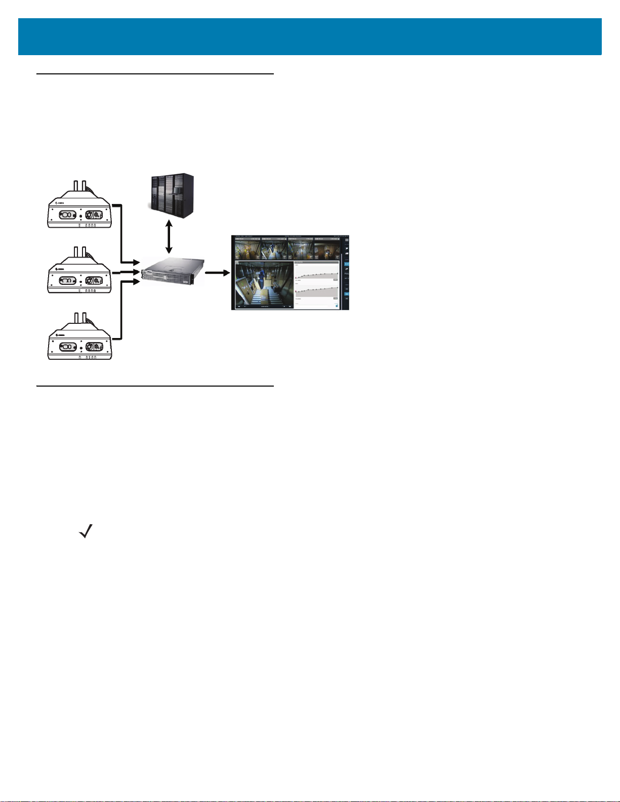
Introduction
The TM2000 captures trailer load information using an onboard RGB camera and 3D sensor, processes the captured data,
and sends the results to a server over a wired or wireless connection. The TM2000 is installed on dock doors at loading
facilities to monitor trailer load progress and provide real time data about important load metrics. The Trailer Load Analytics
(TLA) Dashboard displays this data in a web based interface.
Box Contents and Unpacking
The TM2000 box contains the following items:
• TM2000
• Four mounting screws
• TM2000 Regulatory Guide.
Carefully remove the device from the packaging to avoid damaging the hardware. Inspect the device for damage.
NOTE The mounting bracket is sold separately. For information or to purchase the mounting bracket, contact
your Zebra sales representative.
3
Page 4
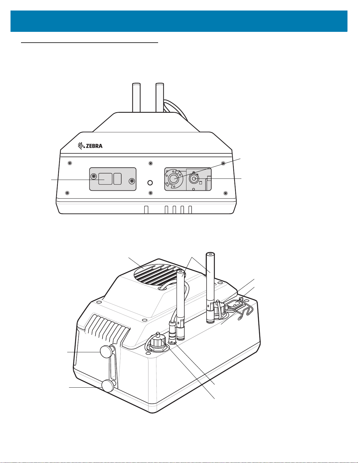
TM2000 Features
Illumination
Source
3D Camera
RGB Camera
Antenna (2)
Locking Screw (2)
Ethernet Connector
Pivot Screw (2)
Fan Connector
USB Connector
A/C Power Connector
Fan
Front View
TM2000 Installation Guide
Top View
4
Page 5
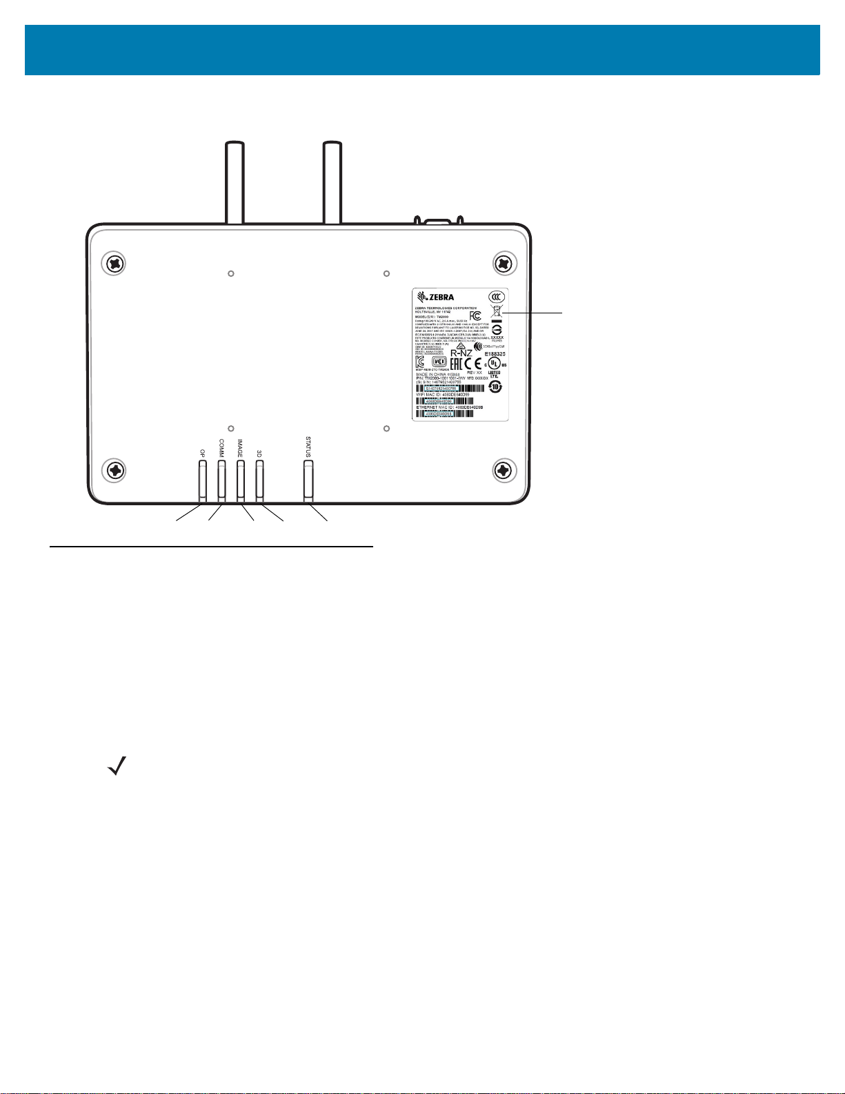
Bottom View
Label
COMM
3D
Image
Status
OP
TM2000 Installation Guide
Installation Requirements
Tools
• Impact drill (an 8mm allen wrench or ratchet hand socket wrench can also be used although it is not as time
efficient)
• Torque wrench with 6 mm allen key
• 3/8 in. hex socket for screws.
Hardware
NOTE Hardware requirements are based on mounting to structural steel.
• Mounting bracket, p/n BRKT-10002-02R (sold separately)
• Four #12 x 1 in., type F, galvanized steel, thread cutting screws (no washers needed) for attaching the mounting
bracket to the door frame (not provided)
• Mounting screws for attaching the device to the mounting bracket
• Power receptacle located near (approximately 1 ft) the top of the dock door frame
• Ladder or step stool.
Software
• Add TM2000 Wi-Fi MAC addresses to the site access point control list (contact your local IT support person).
• If using an ethernet connection, the ethernet MAC address must be added to the control list (contact your local IT
support person).
5
Page 6

TM2000 Installation Guide
Facing Dock
Facing into
Trailer Door
Dock and Trailer markings are located
under the top of the mounting bracket.
Mounting Bracket Holes
Mounting Bracket Installation
IMPORTANT The device power cord is three feet in length. Ensure the electrical receptacle is easily accessible and
located within proper distance to the device.
Installing Mounting Bracket With Template
To install the mounting bracket using the TMU Mounting Bracket Template included in the bracket box:
1. Place the TMU Mounting Bracket Template in the center of the trailer door. Position the edge of the template, facing
the dock, 2 in. from the edge of the dock door frame and tape the template in place.
2. Drill the mounting bracket holes.
3. Remove the template.
4. Install the bracket using four #12 x 1 in. thread cutting screws.
Installing Mounting Bracket Without Template
To install the mounting bracket (without the use of the TMU Mounting Bracket Template):
1. Place the mounting bracket in the center of the trailer door. Position the edge of the bracket, facing the dock, 2 in. from
the edge of the dock door frame.
2. While holding the mounting bracket in position, mark the surface with a pencil through each of the four mounting
bracket holes to determine the location of the screw holes to drill. It is recommended to use four screws to mount the
bracket securely. Use two screws on each side. If there is a center hole (not shown), do not use the center hole.
3. Drill the holes and install the bracket using four #12 x 1 in. thread cutting screws.
6
Page 7
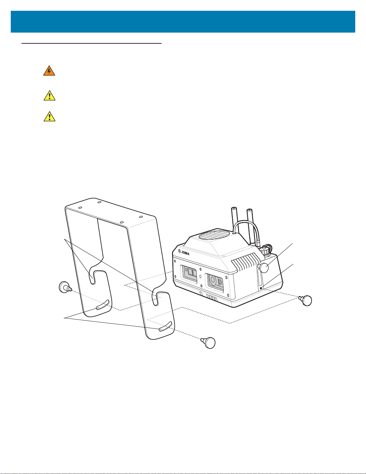
TM2000 Installation Guide
Non-adjustable
Top Mounting
Bracket Pivots
Angle
Adjustment
Slots
Non-adjustable
Top Pivot Screws
(one on each side)
Angle Adjustment
Locking Screws
(one on each side)
TMU Installation
WARNING! Use of controls or adjustments or performance of procedures other than those specified herein may
result in hazardous radiation exposure.
CAUTION Always utilize professional installers to safely install, mount, and supply power to the device. Always ensure
device mounting and power routing meets regional building codes.
CAUTION Double Pole/Neutral Fusing: If a fuse in the neutral conductor is out, the fuse in the line conductor may still be
intact which can result in internal parts remaining energized. Take extreme caution when servicing the unit.
1. Screw and torque the non-adjustable top pivot screws on each side of the device to 4.5 ft-lbs.
2. Make sure the required installation tools are within reach (see Tools on page 5).
3. Place a ladder or step stool at the trailer door.
4. Hang the device on the mounting bracket (see Mounting Bracket Installation on page 6) by sliding the two
non-adjustable top pivot screws into the non-adjustable top mounting bracket pivots.
5. Allow the device to rotate backwards and come to a stop. Release the unit and hand thread the angle adjustment
locking screws. Do not tighten the locking screws in this position.
7
Page 8
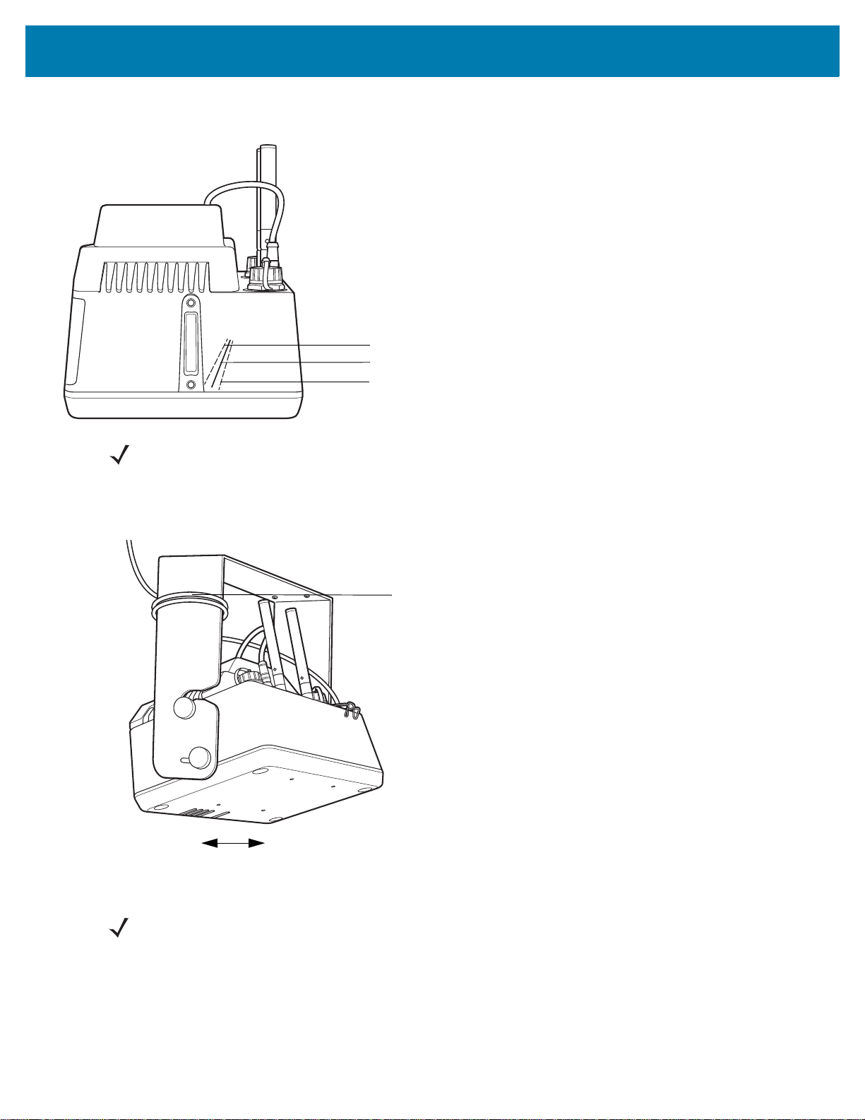
TM2000 Installation Guide
Solid Angle Marking = 20°
Dashed Angle Marking = 12.5°
Dashed Angle Marking = 27.5°
Power Cord Placement
Facing Dock
Facing into
Trailer Door
6. Rotate the device to the proper operating orientation of 20° (minimum angle marking is 12.5°; maximum angle marking
is 27.5°). The angle markings on the device are guidelines only.
NOTE When the TM2000 is connected to the server, it can be viewed on the TLA Dashboard to confirm it has the
proper angle for maximum viewing coverage of the trailer.
7. Torque the angle adjustment locking screws to 4.5 ft-lbs.
8. Wrap the power cord around the bracket. Leave adequate length for the cable to reach the power receptacle at the
trailer door. Do not plug the device in until the installation is complete.
9. Ensure that the antenna’s are positioned vertically.
NOTE The preferred antenna orientation is vertical or 45 degrees (90 degree antenna orientation is not
recommended).
10. Plug the power cord into a socket outlet with earthing connection, which is grounded in accordance with local
regulations. It may take 2-3 minutes for the device to boot up
8
Page 9

11. Check the LEDs for normal operation.
Facing Dock
Facing into
Trailer Door
TM2000 Installation Guide
LED Indicators
The device LED indicators display to indicate status.
• Image - RGB camera indicator lights to indicate the device is taking an image.
• 3D - Depth sensor indicator lights when acquiring a depth image.
• COMM - Wi-Fi communication lights when Wi-Fi is running.
• Status - Provides current operational status of the device.
• OP - Lights to indicate that the device has power.
The standard LED indicators are defined as follows:
Image 3D COMM Status OP Description
--- --- --- --- On Device has power.
--- --- On --- On Wi-Fi is running and accessible.
--- --- Off --- On Wi-Fi interference does not have an IP address or cannot
connect to an AP.
Off On --- --- On Acquiring depth image.
On Off --- --- On Acquiring RGB image.
On On --- --- On Writing PCD or JPG RGB image to file.
Off Off --- --- On Processing scene.
--- --- --- Blinking
Red
(---)
Indicates that the LED may or may not be illuminated
On Depth camera not operational due to the device overheating.
9
Page 10

TM2000 Installation Guide
TM2000 Specifications
Feature Description
Operating System Linux OS with associated drivers for USB, UART, SDIO, I2C, Ethernet and Wi-Fi
CPU 1.5GHz dual-core ARM Cortex A9
NAND Flash 64 GB
SDRAM 1 GB
Environmental
Operating Temperature -30°C to 50°C
Storage Temperature -40°C to 70°C
Dust and Water IP IP54 of IEC529
Power Consumption Maximum: 100W
Initial inrush current: 40A max when operating from 115VAC.
Case Dimensions 11.3 in. x 7.1 in. x 6.3 in.
Depth Sensor
Working Range and Resolution Resolve a1x1x2 ft^3 (X*Y*Z) brown cardboard box at 54 feet
FOV 57.5° x 45°
Image Size 320 x 240
Laser Safety Class 1
Data Interference USB 2.0
Power Consumption Less than 2.5 watts
RGB Camera
Field of View 120°
Data Interference USB 2.0
Power Consumption Less than 2 watts continuous
Frame Rate 30 frames per second
Image Size 1920 x 1080
Depth Capture Rate One per 15 sec
Exposure Time 64 ms max
10
Page 11

TM2000 Installation Guide
Cleaning and Maintenance
Perform routine cleaning and maintenance. To keep the sensor window free of dust and debris, clean regularly using a dry,
soft duster on a long pole.
Service Information
To return a faulty device:
1. Complete a repair return request (RMA) form at: www.zebra.com/repair.
2. Place a clean cloth over the device camera window to protect it from damage during transit.
3. Put the device in a container provided by the on-site contact.
Ship to the repair depot address identified in the RMA.
11
Page 12

www.zebra.com
 Loading...