

Page 1
Part #980476-001 | Rev. A
®
Zebra
R2844-Z
Smart Label Printer
and Encoder
User Guide
TM
Page 2

ii 980476-001A
Page 3

Proprietary Statement
This manual contains proprietary information of the manufacturer. It is intended solely for the information and use of parties operating and maintaining the
equipment described herein. Such proprietary information may not be used, reproduced, or disclosed to any other parties for any other purpose without the
expressed written permission of the manufacturer.
Product Improvements
Continuous improvement of products is a policy of the manufacturer. All specifications and signs are subject to change without notice.
FCC Compliance Statement
NOTE: This equipment has been tested and found to comply with the limits for a Class B digital device, pursuant to Part 15 of the FCC Rules. These limits are
designed to provide reasonable protection against harmful interference in a residential installation. This equipment generates, uses, and can radiate radio
frequency energy and, if not installed and used in accordance with the instructions, may cause harmful interference to radio communications. However, there is
no guarantee that the interference will not occur in a particular installation. If this equipment does cause harmful interference to radio or television reception,
which can be determined by turning the equipment off and on, the user is encouraged to try to correct the interference by one or more of the following measures:
■
Reorient or relocate the receiving antenna.
■
Increase the separation between the equipment and the receiver.
■
Connect the equipment into an outlet on a circuit different than that to which the receiver is connected.
■
Consult the dealer or an experienced Radio/TV technician for help.
NOTE: This unit was tested with shielded cables on the peripheral devices. Shielded cables must be used with the unit to insure compliance.
“The user is cautioned that any changes or modifications not expressly approved by the manufacturer could void the user’s authority to operate the equipment.”
Industry Canada Statement
IC: I28-R2844Z
Operation is subject to the following two conditions: (1) this device may not cause interference, and (2) this device must accept any interference, including
interference that may cause undesired operation of the device.
Liability Disclaimer
The manufacturer takes steps to assure that its published Engineering specifications and Manuals are correct; however, errors do occur. The manufacturer
reserves the right to correct any such errors and disclaims liability resulting therefrom.
No Liability for Consequential Damage
In no event shall the manufacturer or anyone else involved in the creation, production, or delivery of the accompanying product (including hardware and
software) be liable for any damages whatsoever (including, without limitation, damages for loss of business profits, business interruption, loss of business
information, or other pecuniary loss) arising out of the use of or the results of use of or inability to use such product, even if the manufacturer has been advised
of the possibility of such damages. Because some states do not allow the exclusion or limitation of liability for consequential or incidental damages, the above
limitation may not apply to you.
Trademarks and Copyrights
The Zebra logo and the zebra head design are both registered trademarks and R2844-Z is a service mark of ZIH Corp. Windows and MS-DOS are registered
trademarks of Microsoft Corp.
Software® Zebra Technologies Corporation; all rights reserved worldwide. CG Triumvirate is a tradmark of AGFA Monotype Corporation; all rights reserved
worldwide. CG Triumvirate™ Font© AGFA Monotype Corporation. Intellifont™ Portion© AGFA Monotype Corporation; all rights reserved worldwide.
UFST is a registered tradmark of AGFA Monotype Corporation; all rights reserved worldwide. This product incorporates the ZPL®, ZPL II®, and Zebralink™
programs. This product incorporates the Element Energy Equalizer® circuit, and E3® circuit.
All other marks are trademarks or registered trademarks of their respective holders.
This copyrighted manual and the label printer described herein are owned by the manufacturer. All rights are reserved. Unauthorized reproduction of this
manual or the software in the label printer may result in imprisonment of up to one year and fines of up to $10,000 (17 U.S.C.506). Copyright violators may be
subject to civil liability.
©2004 ZIH Corp. All rights reserved.
980476-001A iii
Page 4
Battery
The main printed circuit board assembly includes a three-volt lithium
battery.
CAUTION • Risk of explosion if battery is replaced with an incorrect type.
Note • Recycle batteries according to local your guidelines and regulations.
Shock Hazard
The printer and power supply should never be operated in a location where
either one can get wet. Personal injury could result.
Media and Ribbon
Always use high-quality, approved labels, tags and ribbons. If adhesive
backed labels are used that DO NOT lay flat on the backing liner, the
exposed edges may stick to the label guides and rollers inside the printer,
causing the label to peel off from the liner and jam the printer. Permanent
damage to the print head may result if a non-approved ribbon is used as it
may be wound incorrectly for the printer or contain chemicals corrosive to
the print head. Approved supplies can be ordered from your dealer.
If labels or ribbon run out while printing, DO NOT turn the power switch
OFF (0) while reloading or data loss may result. After loading new
supplies, press the feed button to resume printing.
Static Discharge
The discharge of electrostatic energy that accumulates on the surface of the
human body or other surfaces can damage or destroy the print head or
electronic components used in this device. DO NOT TOUCH the print
head or the electronic components under the top cover.
Thermal Printing
The print head becomes hot while printing. To protect from damaging the
print head and risk of personal injury, avoid touching the print head. Use
only the cleaning pen to perform maintenance.
iv 980476-001A
Page 5

Introduction
Hello!. . . . . . . . . . . . . . . . . . . . . . . . . . . . . . . . . . . . . . . . . . . . . . . . . . . . . 1
What's in the Box?. . . . . . . . . . . . . . . . . . . . . . . . . . . . . . . . . . . . . . . . . . . 2
Inspecting the Printer. . . . . . . . . . . . . . . . . . . . . . . . . . . . . . . . . . . . . . . . . 3
Opening the printer . . . . . . . . . . . . . . . . . . . . . . . . . . . . . . . . . . . . . . . 3
Closing the printer. . . . . . . . . . . . . . . . . . . . . . . . . . . . . . . . . . . . . . . . 5
Reporting Damage . . . . . . . . . . . . . . . . . . . . . . . . . . . . . . . . . . . . . . . 6
Related Documentation . . . . . . . . . . . . . . . . . . . . . . . . . . . . . . . . . . . . . . . 6
Getting Started
Modes of Printing . . . . . . . . . . . . . . . . . . . . . . . . . . . . . . . . . . . . . . . . . . . 7
Attaching Power Supply . . . . . . . . . . . . . . . . . . . . . . . . . . . . . . . . . . . . . . 8
Loading Roll Media. . . . . . . . . . . . . . . . . . . . . . . . . . . . . . . . . . . . . . . . . . 9
Placing the Roll in the Media Compartment. . . . . . . . . . . . . . . . . . . . 9
Adjusting the Guides. . . . . . . . . . . . . . . . . . . . . . . . . . . . . . . . . . . . . 10
Using the Optional Media Adapter Plates. . . . . . . . . . . . . . . . . . . . . 11
Loading Ribbon. . . . . . . . . . . . . . . . . . . . . . . . . . . . . . . . . . . . . . . . . . . . 12
Install the Ribbon Supply Roll . . . . . . . . . . . . . . . . . . . . . . . . . . . . . 12
Install the Take-Up Core. . . . . . . . . . . . . . . . . . . . . . . . . . . . . . . . . . 12
Attach and Tighten the Ribbon. . . . . . . . . . . . . . . . . . . . . . . . . . . . . 13
Operator Controls . . . . . . . . . . . . . . . . . . . . . . . . . . . . . . . . . . . . . . . . . . 14
Power Switch . . . . . . . . . . . . . . . . . . . . . . . . . . . . . . . . . . . . . . . . . . 14
Feed Button . . . . . . . . . . . . . . . . . . . . . . . . . . . . . . . . . . . . . . . . . . . 14
Status Light. . . . . . . . . . . . . . . . . . . . . . . . . . . . . . . . . . . . . . . . . . . . 14
Printing a Test Label . . . . . . . . . . . . . . . . . . . . . . . . . . . . . . . . . . . . . . . . 15
Hooking Up the Printer and Computer . . . . . . . . . . . . . . . . . . . . . . . . . . 16
Interface Cable Requirements. . . . . . . . . . . . . . . . . . . . . . . . . . . . . . 16
USB Interface Requirements . . . . . . . . . . . . . . . . . . . . . . . . . . . . . . 16
Parallel Interface Requirements . . . . . . . . . . . . . . . . . . . . . . . . . . . . 17
Ethernet Interface Requirements. . . . . . . . . . . . . . . . . . . . . . . . . . . . 17
Serial Interface Requirements. . . . . . . . . . . . . . . . . . . . . . . . . . . . . . 17
Contents
980476-001A v
Page 6

Communicating with the Printer . . . . . . . . . . . . . . . . . . . . . . . . . . . . . . . 18
Universal Serial Bus (USB) Communications . . . . . . . . . . . . . . . . . 18
Parallel Communications . . . . . . . . . . . . . . . . . . . . . . . . . . . . . . . . . 18
Internal Ethernet Communications . . . . . . . . . . . . . . . . . . . . . . . . . . 18
Serial Communications. . . . . . . . . . . . . . . . . . . . . . . . . . . . . . . . . . . 19
Adjusting the Print Width . . . . . . . . . . . . . . . . . . . . . . . . . . . . . . . . . . . 20
Adjusting the Print Quality . . . . . . . . . . . . . . . . . . . . . . . . . . . . . . . . . . . 20
Operation & Options
Thermal Printing . . . . . . . . . . . . . . . . . . . . . . . . . . . . . . . . . . . . . . . . . . . 21
Replacing Supplies . . . . . . . . . . . . . . . . . . . . . . . . . . . . . . . . . . . . . . . . . 22
Adding a New Transfer Ribbon . . . . . . . . . . . . . . . . . . . . . . . . . . . . 22
Replacing a Partially Used Transfer Ribbon. . . . . . . . . . . . . . . . . . . 22
Printing in Peel-Mode . . . . . . . . . . . . . . . . . . . . . . . . . . . . . . . . . . . . . . . 23
Printing on Fan-Fold Media . . . . . . . . . . . . . . . . . . . . . . . . . . . . . . . . . . 24
RFID Guidelines
Print Quality Over the Transponder . . . . . . . . . . . . . . . . . . . . . . . . . . . . 27
Supported Transponders . . . . . . . . . . . . . . . . . . . . . . . . . . . . . . . . . . . . . 28
Transmission and Identification Standards. . . . . . . . . . . . . . . . . . . . 29
Manufacturers and Brands . . . . . . . . . . . . . . . . . . . . . . . . . . . . . . . . 30
ZPL II Commands for RFID . . . . . . . . . . . . . . . . . . . . . . . . . . . . . . . . . . 36
^WT – Write Tag . . . . . . . . . . . . . . . . . . . . . . . . . . . . . . . . . . . . . . . 37
^RT – Read Tag . . . . . . . . . . . . . . . . . . . . . . . . . . . . . . . . . . . . . . . . 38
^RS – RFID Setup. . . . . . . . . . . . . . . . . . . . . . . . . . . . . . . . . . . . . . . 40
^RI – RFID Get Tag ID . . . . . . . . . . . . . . . . . . . . . . . . . . . . . . . . . . 42
^RE – Enable/Disable Electronic Article Surveillance Bit. . . . . . . . 44
RFID Programming Examples . . . . . . . . . . . . . . . . . . . . . . . . . . . . . 45
Maintenance
Cleaning. . . . . . . . . . . . . . . . . . . . . . . . . . . . . . . . . . . . . . . . . . . . . . . . . . 53
Print Head Considerations . . . . . . . . . . . . . . . . . . . . . . . . . . . . . . . . 54
Media Path Considerations . . . . . . . . . . . . . . . . . . . . . . . . . . . . . . . . 54
Cleaning Card Considerations . . . . . . . . . . . . . . . . . . . . . . . . . . . . . 54
Platen Considerations . . . . . . . . . . . . . . . . . . . . . . . . . . . . . . . . . . . . 55
Lubrication . . . . . . . . . . . . . . . . . . . . . . . . . . . . . . . . . . . . . . . . . . . . . . . 55
Replacing the Platen . . . . . . . . . . . . . . . . . . . . . . . . . . . . . . . . . . . . . . . . 56
Replacing the Print Head. . . . . . . . . . . . . . . . . . . . . . . . . . . . . . . . . . . . . 57
Thermal-Transfer TLP Model. . . . . . . . . . . . . . . . . . . . . . . . . . . . . . 58
vi 980476-001A
Page 7

Troubleshooting
Resolutions . . . . . . . . . . . . . . . . . . . . . . . . . . . . . . . . . . . . . . . . . . . . . . . 61
Print Quality Problems . . . . . . . . . . . . . . . . . . . . . . . . . . . . . . . . . . . . . . 64
RFID Symptoms . . . . . . . . . . . . . . . . . . . . . . . . . . . . . . . . . . . . . . . . . . . 66
External reader cannot confirm RFID tags are programmed.. . . . . . 66
VOID messages are printed across media. . . . . . . . . . . . . . . . . . . . . 66
Nothing is printed. . . . . . . . . . . . . . . . . . . . . . . . . . . . . . . . . . . . . . . 66
Manual Calibration . . . . . . . . . . . . . . . . . . . . . . . . . . . . . . . . . . . . . . . . 67
Troubleshooting Tests . . . . . . . . . . . . . . . . . . . . . . . . . . . . . . . . . . . . . . 68
Printing a Configuration Label . . . . . . . . . . . . . . . . . . . . . . . . . . . . 68
Recalibration . . . . . . . . . . . . . . . . . . . . . . . . . . . . . . . . . . . . . . . . . . 68
Resetting the Factory Default Values . . . . . . . . . . . . . . . . . . . . . . . . . . . 69
Communications Diagnostics . . . . . . . . . . . . . . . . . . . . . . . . . . . . . . . . . 69
Feed Button Modes . . . . . . . . . . . . . . . . . . . . . . . . . . . . . . . . . . . . . . . . 70
Appendix
Interfaces . . . . . . . . . . . . . . . . . . . . . . . . . . . . . . . . . . . . . . . . . . . . . . . . . 71
Universal Serial Bus (USB) Connector. . . . . . . . . . . . . . . . . . . . . . . 71
Parallel Interface Technical Information . . . . . . . . . . . . . . . . . . . . . 72
ZebraNet® PrintServer II for Ethernet Networks. . . . . . . . . . . . . . . 73
Serial (RS-232) Connector . . . . . . . . . . . . . . . . . . . . . . . . . . . . . . . 74
980476-001A vii
Page 8

980476-001A
Page 9

Hello!
Introduction
This section describes what you get in your shipping box and provides an
overview of printer parts. This section also has procedures that describe
how to open and close the printer and report any problems.
Thank you for choosing a Zebra®R2844-Z™ printer, a high-quality
on-demand printer with RFID (radio-frequency identification) capability
manufactured by the industry leader in quality, service, and value—Zebra
Technologies Corporation. For over 25 years, Zebra Technologies
Corporation has provided customers with the highest caliber of products
and support.
Your R2844-Z printer provides thermal-transfer printing (which uses
ribbon) and direct-thermal printing.
This manual provides all of the information you will need to operate your
printer on a daily basis. To create label formats, refer to the RFID-specific
ZPL II commands in this guide and the ZPL II Programming Guide. The
programming guide is available by contacting your distributor or Zebra
Technologies Corporation.
NOTE • Many printer settings may also be controlled by your printer’s driver or label
preparation software. Refer to the driver or software documentation for more
information.
Your printer, when connected to a host computer, functions as a complete
system for printing labels and tags, especially those with RFID applications.
980476-001A 1
Page 10

What's in the Box?
Save the carton and all packing materials in case you need to ship or store
the printer later. After unpacking, make sure you have all parts. Follow the
procedures for inspecting the printer to familiarize yourself with printer
parts so you can follow the instructions in this book.
2 980476-001A
Page 11

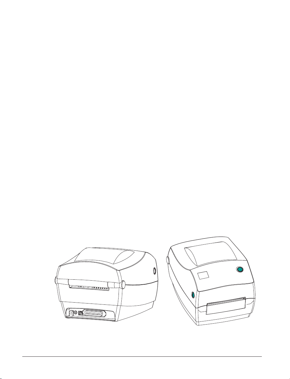
Inspecting the Printer
Look at the outside of the printer and make sure that all parts are present.
Opening the printer
To access the media compartment, you
must open the printer.
Pull the release levers towards you and lift
the cover.
980476-001A 3
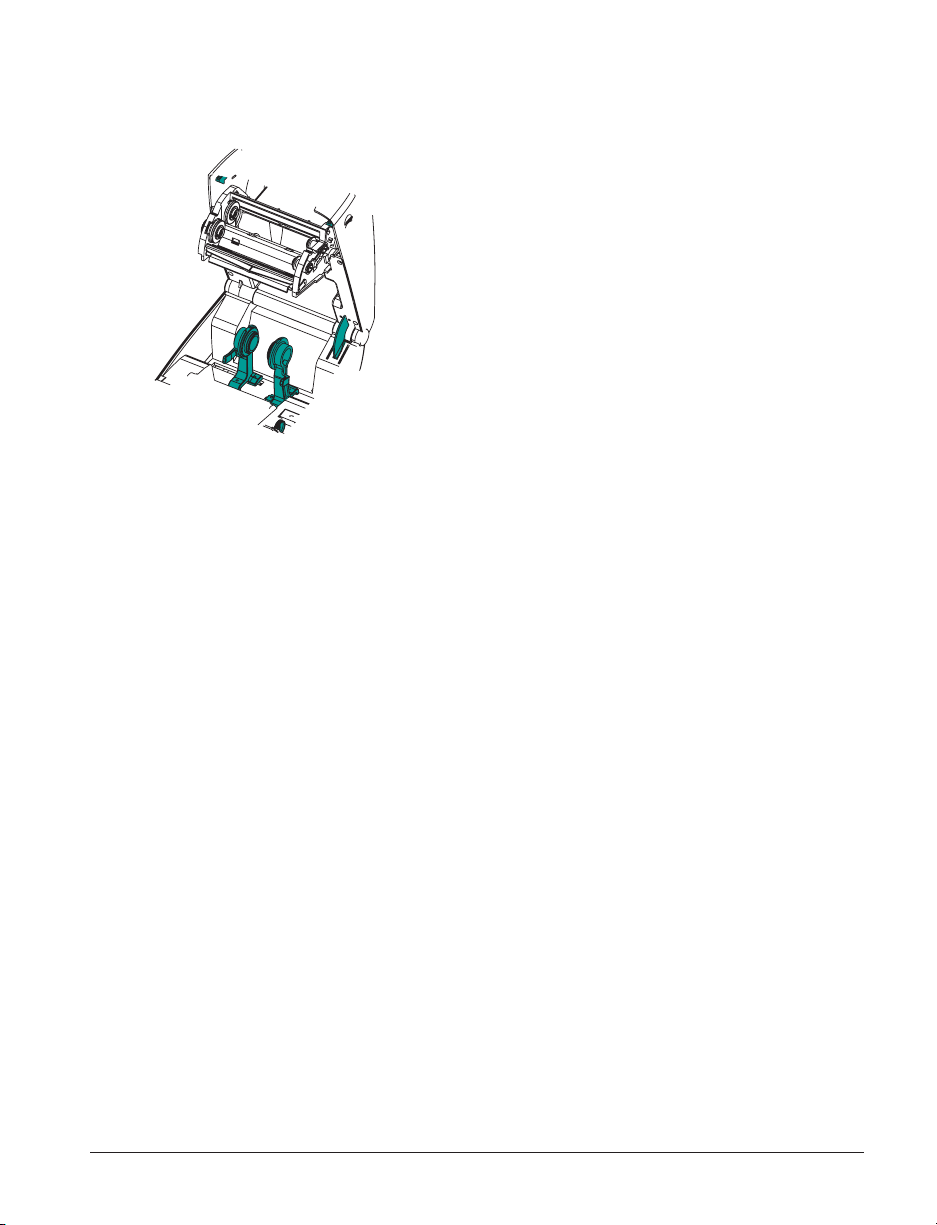
Page 12

INSPECTING THE PRINTER (continued)
After opening the printer, check the media compartment.
4 980476-001A
Page 13
Closing the printer
Hold the top cover and press the
“kick-stand” cover lock to release.
Lower the top cover. The ribbon
carriage automatically folds up into place.
Press down until the cover snaps closed.
980476-001A 5
Page 14

Reporting Damage
If you discover damage or missing parts:
■
Immediately notify and file a damage report with the shipping company.
The manufacturer is not responsible for any damage incurred during
shipment of the printer and will not cover the repair of this damage
under its warranty policy.
■
Keep the carton and all packing material for inspection.
■
Notify the authorized reseller
Related Documentation
Depending on the options you have ordered or choose to use with your new
printer, you will find the following documents helpful:
■
ZPL II® Programming Guide
■
ZebraNet® PrintServer IITMfor Ethernet Networks Installation and
Operation Guide
■
Universal Serial Bus Specification available from the USB
Implementation Forum
6 980476-001A
Page 15

This section describes how to set up your printer for the first time and use
the most common operating procedures for loading media in tear-off mode
and loading ribbon.
Modes of Printing
You can operate this printer in different modes:
■
Standard tear-off mode allows you to tear off each label (or a strip of
labels) after it is printed.
■
In optional peel-off mode, the backing material is peeled away from the
label as it is printed. After this label is removed, the next one is printed.
The printer typically uses roll media, but you can use fan-fold or other
continuous media as well.
For procedures to use optional modes and features, refer to the Operation
and Options section.
Getting Started
980476-001A 7
Page 16

Attaching Power Supply
y
Check the power supply to make certain it is appropriate for your input
voltage.
Caution • Use the power supply that came with your printer. Never operate the
printer and power supply in an area where they can get wet. Serious personal injury
could result!
1. Make sure the power switch is in the off position (down).
2. The DC power supply has a barrel connector on one end that must be
inserted into the power supply receptacle on the back of the printer.
3. Insert the separate AC power cord into the power supply.
4. Plug the other end of the cord into an appropriate AC electrical outlet.
Plug
Varies b
Country
AC
Power
Cord
Power
Switch
Power
Supply
Receptacle
Barrel
Connector
Power
Supply
8 980476-001A
Page 17

Loading Roll Media
When you load media, you must place the roll on the media hangers and
then adjust the media guides.
You must use the correct media for the type of printing you require. When
printing without a ribbon, you must use direct thermal media. When using
ribbon, you must use thermal transfer media. The printer's ribbon sensor
detects motion of the supply spindle.
Placing the Roll in the Media Compartment
Whether your roll media is inside or
outside wound you load it into the printer
the same way.
1. Open the printer. Remember that you
need to pull the release levers toward
the front of the printer.
2. Remove the outside length of media.
During shipment, the roll may become
dirty when handled or dusty when
stored. Removing the outside length
avoids dragging adhesive or dirty
media between the print head and
platen.
3. Separate and hold open the media
hangers.
4. Orient the media roll so that its
printing surface will be up as it passes
over the platen.
5. Lower the roll between the hangers
and close them onto the core.
980476-001A 9
Page 18

Adjusting the Guides
The adjustable guides direct the media
toward the platen and print head.
1. Open the media guides by turning the
guide adjuster knob to the rear.
2. Thread the media through the guides.
3. Close the media guides by turning the
guide adjuster knob to the front. They
should just touch, but not restrict, the
edges of the media.
4. Unless you need to load ribbon, close
the top cover. Remember that you
need to release the cover lock, lower
the top cover, and press down until the
latches snap into place.
10 980476-001A
Page 19

Using the Optional Media Adapter Plates
If your media roll has a larger diameter
core, you can use an accessory to adapt
the core to the media holders.
1. Note which position will fit the
diameter of the roll core.
2. On the left side plate, align the pegs
with the screws and use a small
Phillips driver to tighten them.
3. On the right side plate, align the pegs
with the screws and use a small
Phillips driver to tighten them.
4. Align the plates so that the pegs hold
the roll core and press together.
5. Place the roll into the media
compartment.
980476-001A 11
Page 20

Loading Ribbon
You must use thermal transfer media (accepts wax and/or resin transferred
off a ribbon) when you use a ribbon. When loading ribbon, you install the
supply and take-up rolls, then tighten the ribbon on the carriage.
Install the Ribbon Supply Roll
Before following these steps, prepare the
ribbon by removing its wrapping and
pulling its adhesive strip free.
1. Thread the ribbon through the
carriage.
2. Press the right side onto the supply
hub.
3. Align the notches on the left side and
mount onto the spokes of the left hub.
Install the Take-Up Core
1. Press the right side onto the take-up
hub.
2. Align the notches on the left side and
mount onto the spokes of the left hub.
You can find your first ribbon take-up
core in the packing box. Subsequently,
use the empty supply core to take up the
next roll of ribbon.
12 980476-001A
Page 21

Attach and Tighten the Ribbon
You must align the ribbon so that it will
be taken straight onto the core.
1. Attach the ribbon to the take up core.
Use the adhesive strip on new rolls;
otherwise, use tape.
2. Turn the ribbon take-up gear
counter-clockwise (top moves toward
rear) to remove slack from the ribbon.
3. Close the top cover. Remember that
you need to release the cover lock,
lower the top cover, and press down
until the latches snap into place.
980476-001A 13
Page 22
Operator Controls
Power Switch
Press up to turn ON or down to turn OFF the printer.
CAUTION • The power should be turned off before connecting or disconnecting the
communications and power cables.
Feed Button
Press once to feed one blank label.
Press once to take the printer out of a “pause” condition. (The printer is put
into “pause” by either a programming command or an error condition.) See
“What the Status Light is Telling You” on page 61.
Use the Feed button for printer setup and status (see “Feed Button Modes”
on page 70).
Status Light
Functions as a printer operational indicator (see “What the Status Light is
Telling You” on page 61).
14 980476-001A
Page 23

Printing a Test Label
PRINTER CONFIGURATION
Zebra Technologies
ZTC R2844-Z-200dpi
+10 DARKNESS
................
+000 TEAR OFF
...............
TEAR OFF PRINT MODE
NON-CONTINUOUS MEDIA TYPE
WEB SENSOR TYPE
THERMAL-TRANS. PRINT METHOD
104 0/8 MM PRINT WIDTH
12 LABEL LENGTH
39 988 .....
NOT CONNECTED ...... USM COMM.
PARALLEL........... PARALLEL COMM.
RS232 ............. SERIAL COMM.
860 ...............
8 BITS DATA BITS
NONE PARITY
XON/XOFF HOST HANDSHAKE
NONE PROTOCOL
000 NETWORK ID
NORMAL MODE COMMUNICATIONS
<˜> 7EH CONTROL PREFIX
<^> 5EH FORMAT PREFIX
<,> 2CH DELIMITER CHAR
ZPL II ZPL MODE
FEED...............
FEED HEAD CLOSE
DEFAULT BACKFEED
+020 LABEL TOP
+0000 LEFT POSITION
029 WEB S.
068 MEDIA S.
050 RIBBON S.
050 MARK S.
001 MARK MED S.
062................ MEDIA LED
000................ RIBBON LED
081................ MARK LED
CS MODES ENABLED
.. MODES DISABLED
832 8/MM FULL RESOLUTION
SP.814.B <- FIRMWARE
V2.2.6.98.C HARDWARE ID
CUSTOMIZED CONFIGURATION
1024.............R: RAM
0768.............E: ONBOARD FLASH
NONE FORMAT CONVERT
................... TWINAX/COAX ID
NONE OPTION
NONE ZEBRA NET II
OEM 4F
FIRMWARE IN THIS PRINTER IS COPYRIGHTED
...........
................
48...............
.0IN MM MAXIMUM LENGTH
0 BAUD
.............
...............
...............
................
.............
...............
...............
..............
................
................
................
................
................
.................
.................
...............
...............
...............
400:Ver. 2. RFID VERSION
.....
.....
.........
...........
........
...........
...........
...........
............
......
.....
........
.........
MEDIA POWER UP
Before you connect the printer to your
computer, make sure that the printer is in
proper working order. You can do this by
printing a configuration label.
1. Make sure the media is properly
loaded and the top cover of the printer
is closed. Then, turn the printer
power on if you have not already done
so.
2. When the status light is solid green,
press and hold the feed button until
the status light flashes once.
3. Release the feed button. A
configuration label will print.
If you cannot get this label to print, refer
to Troubleshooting on page 61.
980476-001A 15
Page 24

Hooking Up the Printer and Computer
Your printer will have one of two combinations of interfaces:
■
Universal Serial Bus (USB), parallel and serial
■
MOVIE
Interface Cable Requirements
USB, ethernet, and serial
Each specific interface option—USB, parallel, ethernet, serial—is discussed
individually.
You must supply the required interface cable for your application.
CAUTIONS • Keep the power switch in the OFF position when attaching the
interface cable.
The power supply barrel connector must be inserted into the power supply
receptacle on the back of the printer before connecting or disconnecting the
communications cables.
This printer complies with FCC “Rules and Regulations,” Part 15, for Class B
Equipment, using fully shielded six-foot data cables. Use of longer cables or
unshielded cables may increase radiated emissions above the Class B limits.
Data cables must be of fully shielded construction and fitted with metal or
metalized connector shells. Shielded cables and connectors are required to
prevent radiation and reception of electrical noise.
To minimize electrical noise pickup in the cable:
Keep data cables as short as possible (6’ [1.83 m] recommended).
Do not tightly bundle the data cables with power cords.
Do not tie the data cables to power wire conduits.
USB Interface Requirements
Universal Serial Bus (version 1.1) provides a high-speed interface that is
compatible with your existing PC hardware. USB’s “plug and play” design
makes installation easy. Multiple printers can share a single USB port/hub.
16 980476-001A
Page 25

Parallel Interface Requirements
The required cable (IEEE 1284-compliant is recommended) must have a
standard 36-pin parallel connector on one end, which is plugged into the
parallel port located on the back of the printer. The other end of the parallel
interface cable connects to the printer connector at the host computer.
For pinout information, refer to page 72.
Ethernet Interface Requirements
Ethernet provides a powerful networking capability that can be of use in a
variety of internet/intranet printing solutions. After you load media and
close the top cover, you can press the test button next to the connector on
the rear of the printer to get an ethernet configuration label.
Serial Interface Requirements
The required cable must have a nine-pin “D” type (DB-9P) male connector
on one end, which is plugged into the mating (DB-9S) serial port located on
the back of the printer. The other end of this signal interface cable connects
to a serial port at the host computer. Depending on the specific interface
requirements, this will most likely be a null modem cable.
For pinout information, refer to page 74
980476-001A 17
Page 26

Communicating with the Printer
Universal Serial Bus (USB) Communications
The printer is a terminal device when using a universal serial bus interface.
You can refer to the Universal Serial Bus Specification for details regarding
this interface.
Parallel Communications
When using the parallel port, typically there is no setup is required once the
cable is plugged in. If you should encounter any problems, consult the
user’s guide that came with your computer.
Internal Ethernet Communications
For details regarding this interface, refer to the ethernet guide from the
manufacturer.
18 980476-001A
Page 27

Serial Communications
Serial communications between the printer and the host computer can be set
by either autobaud synchronization or the
Autobaud
Autobaud synchronization allows the printer to automatically match the
communication parameters of the host computer. To autobaud:
1. Press and hold the feed button until the green status LED flashes once,
twice, and then three times.
2. While the status LED flashes, send a ZPL II format to the printer.
3. When the printer and host are synchronized, the LED changes to solid
green. (No labels will print during autobaud synchronization.)
^SC Command
^SC
command.
Use the Set Communications (
communications settings on the printer.
1. With the host computer set at the same communications settings as the
printer, send the
settings.
2. Change the host computer settings to match the new printer settings.
Refer to the ZPL II Programming Guide for more information about this
command.
^SC
^SC
) command to change the
command to change the printer to the desired
Defaulting the Serial Parameters
To reset the communications parameters on the printer to the factory
defaults (9600 baud, 8 bit word length, no parity, 1 stop bit, and
XON/XOFF), do the following:
1. Press and hold the feed button until the green status LED flashes once,
twice, and then three times.
2. While the status LED rapidly flashes amber and green, press the feed
button.
980476-001A 19
Page 28

Adjusting the Print Width
Print width must be calibrated when:
■
You are using the printer for the first time.
■
There is a change in the width of the media.
Print width may be set by way of the five-flash sequence in “Feed Button
Modes” (see page 70) or refer to the Print Width (
your ZPL II Programming Guide).
Adjusting the Print Quality
Print quality is influenced by the heat of the print head, the speed of the
media and the type of media you are using. Only by experimenting will
you find the optimal mix for your application.
The relative darkness setting is controlled by either the six-flash sequence
in “Feed Button Modes” (see page 70) or the Set Darkness (
command (follow the instructions in the ZPL II Programming Guide).
If you find that the print speed needs to be adjusted, refer to the Print Rate
(
^PR
) command in the ZPL II Programming Guide.
^PW
) command (consult
~SD
) ZPL II
20 980476-001A
Page 29

Operation & Options
This section helps you get the most from your printer.
You must use programming to control many of the printer’s functions. A
few examples:
■
The
~JL
command controls label length.
■
The
^XA^MTD^XZ
thermal; the
thermal transfer.
■
The
^XA^JUS^XZ
For detailed information about creating labels using ZPL II, refer to the ZPL
II Programming Guide or visit our web site at www.zebra.com.
To improve print quality, changing both print speed and density may be
required to achieve the desired results. Your application’s printer driver
provides control of the speed and heat (density).
command changes the printing mode to direct
^XA^MTT^XZ
command saves the new settings to flash memory.
command changes the printing mode to
Thermal Printing
The print head becomes hot while printing. To protect from damaging the
print head and risk of personal injury, avoid touching the print head. Use
only the cleaning pen to perform maintenance.
The discharge of electrostatic energy that accumulates on the surface of the
human body or other surfaces can damage or destroy the print head or
electronic components used in this device. You must observe static-safe
procedures when working with the print head or the electronic components
under the top cover.
You must use the correct media for the type of printing you require. When
printing without a ribbon, you must use direct thermal media. When using
ribbon, you must use thermal transfer media. The printer’s ribbon sensor
detects motion of the supply spindle.
980476-001A 21
Page 30

Replacing Supplies
If labels or ribbon run out while printing, leave the printer power on while
f labls or ribbonoll,he elose thFeed buttbbotosls tart .leIadhesivile
e the printewaitosfs oyou toIado a fls horoll.le
Page 31

Printing in Peel-Mode
The optional dispenser allows you
to print in “peel-mode” where the
label backing follows a different path and
the labels are presented one at a time for
subsequent placement.
Before using peel-mode, you must send
the programming commands
^XA ^MMP ^XZ
^XA ^JUS ^XZ
to the printer. Refer to your ZPL II
Programmer’s Manual.
1. Remove several labels from the
backing material.
2. Open the top cover.
3. Open the dispenser door.
4. Switch on the label-taken sensor.
5. Insert the backing in front of the peel
bar and behind the peel roller.
6. Close the dispenser door.
7. Close the top cover.
8. Press the Feed button to advance the
label.
During the print job, the printer will peel
off the backing and present a single label.
Take the label from the printer so it will
print the next label.
980476-001A 23
Page 32

Printing on Fan-Fold Media
Printing on fan-fold media requires you to
set both the media hangers and the media
guides in position.
1. Open the top cover.
2. With a sample of your media, adjust
the media hangers to the width of the
media. The hangers should just touch,
but not restrict, the edges of the
media.
3. Tighten the screw using a small
Phillips driver #1.
4. With a sample of your media, adjust
the guides to the width of the media.
The guides should just touch, but not
restrict, the edges of the media.
5. Insert the media through the slot at the
rear of the printer.
6. Run the media between the hangers
and guides.
7. Close the top cover.
24 980476-001A
Page 33

RFID Guidelines
The Zebra R2844-Z Smart Label Printer and Encoder serves as dynamic
tool for both printing and programming smart labels and tags. These labels
and tags are usually made from two components, media and an RFID (radio
frequency identification) transponder.
■
The media is comprised of synthetic- or paper-based material that can be
printed upon using direct thermal or thermal transfer printing techniques.
The media is typically made from the same materials and adhesives used
by a standard barcode printer.
■
The transponder is usually comprised of an antenna coil that is bonded
to an integrated circuit (IC) chip. The IC contains the drivers, coders,
decoders and memory. At a minimum, the transponder has memory that
can be read, while the vast majority also have memory that can be
programmed by the user as well.
Media
Liner
Transponder
Media
Transponder
Outline of
transponder
(
shape varies
by manufacturer
Media
Supply
)
980476-001A 25
Page 34

The communication between the RFID tag and the printer is established
when the transponder lines up with the printer’s antenna.
Note • The transponder position, prior to encode/decode, is critical. The optimal
transponder position varies with antenna coil size and type of RFID IC used. It is
important to use media and tags that have been specifically designed for use in this
printer. Failure to do so may result in the inability to read or program the embedded
RFID tags.
Printing and programming of smart labels is handled through the use of
Zebra's printer programming language, ZPL. The printer segments the
received ZPL's RFID-specific and printing-related commands. The printer
will execute the RFID commands first, followed by those for printing
barcodes and text. Each transponder has blocks of addressable memory that
are written to and read from through ZPL commands. Many transponders
also contain a pre-programmed unique ID/serial number. The ZPL
commands also provide for exception handling, such as setting the number
of read/write retries before declaring the transponder defective.
Transponders
imbedded
in media
Media
Supply
Bracket
Ribbon
Supply
Reader/Writer
Board
Ribbon
Take-up
Antenna
26 980476-001A
Page 35

If an RFID tag is declared defective (fails to program correctly or cannot be
detected) the printer ejects it and prints the word "void" across the entire
label (see samples on page 45). If problems persist, this process—using the
same data and format—will continue from one to ten tags; you set the
retries using a parameter in the RFID Setup command (^RS). After the last
tag is ejected the printer removes the customer format from the print queue,
and proceeds with the next format (if one exists in the buffer).
Print Quality Over the Transponder
There is a raised area on each label immediately around the location of the
IC chip where the printer may print with low quality.
Design your printed label around the location of the chip in the type of
approved smart label you select. For best results, do not print barcodes
directly over the transponder. If in doubt, check the print quality and adjust
the label format, or obtain smart labels with an alternate transponder
placement.
Top View
Profile
980476-001A 27
Page 36

Supported Transponders
Use transponders specifically approved for use in the R2844-Z printer.
Failure to do so may result in the inability to read or write to imbedded
RFID tags. For a current list of approved transponders, contact Zebra
Technologies Corporation or visit the website (http://www.rfid.zebra.com).
As new transponders become commercially available, Zebra will evaluate
them for compatibility with the R2844-Z printer.
Important • Function of an encoded smart label in an application depends on factors
such as where the label is placed on an item (such as a carton or a pallet) as well as
on the contents of the items (such as metals or liquids). Contact the supplier of your
external RFID reader for assistance with these types of issues. Zebra can only
support issues regarding printing and encoding smart labels.
28 980476-001A
Page 37

Transmission and Identification Standards
ISO-15693
ISO-15693 is an international standard for 13.56 MHz RFID devices. As
this is a public standard, tags and integrated circuits may be produced by a
wide variety of manufacturers. The current standard stipulates that
manufacturers may configure memory in various ways (up to 256 blocks
comprising a block size up to 256 bits (32 bytes)). The standard also
stipulates that a manufacturer may, or may not, use the recommended
methods of reading and writing to the tag as stipulated in the standard. For
these reasons, the printer may not be compatible with every manufacturer's
ISO-15693 transponders. Contact your technical support representative for
the latest list of supported ISO-15693 transponders.
For more information, see the International Standards Organization web
site at:
http://www.iso.org
Electronic Product Code™ (EPC™)
The Electronic Product Code™ (EPC™) is a product numbering standard
that can be used to identify a variety of items using RFID technology. The
EPC format contains 12-bytes (96-bits) of data defining the manufacturer,
product, and serial number. The EPC can link to an online database,
providing a secure way of sharing product-specific information along the
supply chain.
For more information, see the EPCglobal web site at:
http://www.epcglobalinc.org
980476-001A 29
Page 38

Manufacturers and Brands
In your printer, you can use these brands of transponders:
■
Texas Instruments® Tag-it™
■
Philips® I•Code
■
Inside Technologies Picotag® 2K
■
Infineon Technologies® my-d vicinity
30 980476-001A
Page 39

Texas Instruments® Tag-it™ Transponders
Texas Instruments transponders are high frequency (13.56MHz) RFID
devices. Each transponder has 256 bits of memory. Data is segmented into
4-byte (32-bit) blocks that are uniquely addressable, for a total of 8 blocks.
Each memory block is lockable using the write protect function during the
writing process.
Texas Instruments Tag-it™ Blocks
Block # Description Bytes
0 User Data
1 User Data
2 User Data
3 User Data
4 User Data
5 User Data
6 User Data
7 User Data
Texas Instruments ISO15693
Block
32 User
Page 40

Philips® I•Code Transponders
Philips I•Code transponders are high frequency (13.56MHz) RFID devices.
Each transponder has 512 bits of memory. Data is segmented into 4 byte
(32 bit) blocks that are uniquely addressable for a total of 16 blocks. Each
memory block is lockable using the write protect function during the
writing process. The first two blocks of data (block 0 and 1) are
pre-programmed, non-changeable, and are used for storage of a unique 64
bit serial number. The next two blocks (blocks 2 and 3) are used for storage
of configuration information; block 4 is used for family or application
identification and blocks 5 to 15 are free for user application use.
If you are using these transponders for your own use, and don’t require
universal special function or family codes, then you can program blocks 3
through 15.
Philips I•Code Blocks
Block # Description Bytes
0 Serial Number (write protected)
1 Serial Number (write protected)
2 Write Protect Block (Caution)
3 Special Function Block
4 Family Code
5 User Data
6 User Data
7 User Data
8 User Data
9 User Data
10 User Data
11 User Data
12 User Data
13 User Data
14 User Data
15 User Data
8 Optional
40 User
Note • The bits in block 2 determine the write access conditions for itself and each of
the remaining blocks. You can leave blocks 2 through 15 open or you can
write-protect them. Write-protected blocks (included block 2) can never be written to
from the moment they are locked
32 980476-001A
Page 41

Block
-4
-3
-2
-1
0
1
2
...
26
27
Philips I•Code ISO15693
Byte number within a block
012 3
Unique
Identifier 0
Unique
Identifier 4
Internally
Used
Unique
Identifier 1
Unique
Identifier 5
Electronic
Article
Surveillance
Unique
Identifier 2
Unique
Identifier 6
Application
Family
Identifier
Unique
Identifier 3
Unique
Identifier 7
Data Storage
Format
Identifier
Write Access Conditions
00 00 00 00
User Data
980476-001A 33
Page 42

Inside Technologies Picotag® Transponders
Inside Technologies Picotag® transponders are high frequency (13.56MHz)
RFID devices. Each transponder has 2048 bits of memory. Data is
segmented into 8 byte (64 bit) blocks that are uniquely addressable for a
total of 31 blocks. Blocks 6 to 12 are lockable using the write protect
function during the writing process. The first block of data (block 0) is
pre-programmed and is used for storage of a unique 64 bit serial number.
The next two blocks (blocks 1 and 2) are used for storage of configuration
information; blocks 3 to 31 are free for user application use.
Inside Technologies Picotag® 2K
Block
0 Serial Number (64 bits)
1
2 Application Issuer Area
3
5
6
7
8
9
10
11
12
13
31
0123456 7
FFh
Application
16-bit OTP
Byte number within a block
Block
Area
Block Write Lockable Application Area
Write
Lock
Application Area4
Application Area...
Tun-
ing
Cap
1Fh E.A.S. Fuses
34 980476-001A
Page 43

Infineon Technologies® my-d vicinity Transponders
Infineon Technologies® my-d vicinity transponders are high frequency
(13.56MHz) RFID devices. Each transponder has 10,000 bits of memory.
Data is segmented into 128 pages where each page has 8 bytes data storage
and 2 bytes administrative storage.
Infineon Technologies® 10K ISO15693
Block
0 Unique ID Number — Read Only
1
2
3
4
...
7E
7F
Block
0 Unique ID Number — Read Only
1
2
3
4
...
1E
1F
0123456 7
Infineon Technologies® 2K ISO 15693
0123456 7
Byte number within a block
Manufacturer's Information — Read Only
User Data
Byte number within a block
Manufacturer's Information — Read Only
User Data
980476-001A 35
Page 44

ZPL II Commands for RFID
Valid programming requires that printer instructions begin with the Start
Format command (^XA) and finish with the End Format command (^XZ);
they are the opening and closing brackets, respectivley, of a label format
instruction.
This subsection describes the RFID-related commands:
■
^WT – Write Tag
■
^RT – Read Tag
■
^RS – RFID Setup
■
^RI – RFID Get Tag ID
■
^RE – Enable/Disable Electronic Article Surveillance Bit
36 980476-001A
Page 45

^WT – Write Tag
The format for the ^WT instruction is:
where the parameters are:
b = block number
Default value: 0
Other values: 1 to n, where n is the maximum number of
blocks for the tag
This is the starting block number. If the user sends more than a block of data it
will overflow into the next block. If the user overflows the block and
subsequent blocks cause errors (write protects, beyond range, etc.), the write
will be aborted, but blocks already written will not revert to original contents.
It’s up to the user to ensure blocks aren’t accidentally overwritten.
r = retries
Default value: 0
Other values: 1 to 10, number of retries
m = motion
Default value: 0 (Feed label after writing)
Other value: 1 (No Feed after writing, other ZPL may cause
a feed)
w = write protect
Default value: 0 (NOT write protected)
Other value: 1 (Write protect)
^WTb,r,m,w,f,v
f = data format
Default value: 0 (ASCII)
Other value: 1 (Hexadecimal)
v =
Not used for this printer.
If there is an error within the data for the transponder, the printer acts
according to the error handling parameter of the RFID Setup command
(^RS).
980476-001A 37
Page 46

^RT – Read Tag
The format for the ^RT instruction is:
where the parameters are:
# = number to be assigned to the field
Default value: 0
Other Values: 1 to 9999
b = starting block number
Default value: 0
Other values: 1 to n, where n is the maximum number of
blocks for the tag
n = number of blocks to read
Default value: 1
Other values: 2 to n, where n is maximum number of blocks
minus starting block number. In other words, if the tag has 8
blocks (starting with block 0) and you’re starting with block 6,
n can be 2. This would give you block 6 and block 7
information.
f = format
Default value: 0 ASCII
Other value: 1 Hexadecimal
^RT#,b,n,f,r,m,s
r = retries
Default value: 0
Other values: 1 to 10, number of retries
m = motion
Default value: 0 (Feed label after writing)
Other value: 1 (No Feed after writing, other ZPL may cause
a feed)
s =
Default value: 0 (Least Significant Byte first)
Other value: 1 (Most Significant Byte first)
38 980476-001A
Page 47

^RT – Read Tag (continued)
Example: This reads a block from a tag, and prints it on a label:
^XA
^RS1,0^FS
^FO20,120^A0N,60^FN1^FS
^FO20,100^A0N,20^FN2^FS
^RT1,7,3,0,5,0,0^FS
^RT2,2,2,0,5,0,0^FS
^XZ
The first ^RT command automatically detects the tag type, starting at block
7, reads three blocks of data in ASCII format. It will retry the command 5
times if necessary. A “void” label will be generated if the read is
unsuccessful after ‘r’ retries. The data read will go into the ^FN1 location
of the recalled format.
The second ^RT command automatically detects the tag type, starting at
block 2, and reads two blocks of data in ASCII format. It retries up to 5
times. The data read will go into the ^FN2 location of the recalled format.
You can send data back to the host with the Host Verification command
(^HV). Refer to the ZPL II manual to learn about this command.
980476-001A 39
Page 48

^RS – RFID Setup
Use this command to set up RFID operation and error handling. You can
move the tag into an effective area to read or write.
The format for the ^RS instruction is:
^RSt,p,v,n,e
where the parameters are:
t = tag type
Default value: 1 –Auto Detect (automatically determine the
tag type, by querying the tag)
Other values:
2- Texas Instruments Tag-it™ tags
3- Philips I•Code tags
4- Inside Technologies Picotag® 2K
5- ISO 15693 tag (see note)
6- EPC Tag (13.56 MHz)
p = read/write position of a transponder in vertical (Y-axis) in
dot-rows from the top of the label.
Default value: label length minus eight dot-rows
Other values: zero to label length
Set to zero ( 0 ) so that the media will not move; that is, the
transponder is already in the effective area.
v = length of void print out in vertical (Y-axis) dot-rows.
Default value: label length
Other values: zero to label length
n = number of labels to try in case of read/encode failure
Default value: 3
Other values: 1 to 10, number of labels
e = error handling
Default value: 'N' (no action)
Other values:
'P'- printer pauses
'E'- printer goes into error mode
40 980476-001A
Page 49

^RS – RFID Setup (continued)
If the read/encode retries exceed the number set by the "n" parameter, an
error will be sent to the host as an unsolicited message. To control the
unsolicited message, use the ZebraNet Alert commands (^SX and ^SQ) and
set the "condition type" parameter to "P."
Note • Use caution when using this function in combination with ^RI (reading the
unique ID number) or ^RT (reading tag data). Problems can occur if the data read
from the tag is going to be printed on the label. Any data read from the transponder
must be positioned to be printed above the read/write position. Failure to do this will
prevent read data from being printed on the label or tag.
980476-001A 41
Page 50

^RI – RFID Get Tag ID
The format for the ^RI instruction is:
^RI#,f,r,m
where the parameters are:
# = field number to store the unique ID
Default value: 0
Other values: 1 to 9999
f = format
Default value: 0- MSB first for ISO15693. LSB first in
other tags.
Other value: 1- LSB first for ISO15693. MSB first in
other tags.
r = retries
Default value: 0
Other values: 1 to 10, number of tries
m = motion
Default value: 0 (feed)
Other value: 1 (no feed)
The printer reads the ID from the tag so that it can be printed or returned to
the host by using the Host Verification command (^HV).
42 980476-001A
Page 51

^RI – RFID Get Tag ID (continued)
The example below reads the unique ID/serial number from a tag, and
prints it on a label:
^XA
^FO100,100^A0N, 60^FN0^FS
^RI0^FS
^FD ^FS
^XZ
980476-001A 43
Page 52

^RE – Enable/Disable Electronic Article Surveillance Bit
Use this command to set the Electronic Article Surveillance (E.A.S.) bit.
This command has no effect on transponders (such as the Texas Instruments
ISO 15693) that do not support E.A.S. capabilities.
The format for the ^RE instruction is:
where the parameters are:
t = set the E.A.S. bit
Default value: 'n' (Disable E.A.S.)
Other value: 'y' (Enable E.A.S.)
r = retries
Default value: 0
Other values: 0 to 10, number of retries
^REt,r
44 980476-001A
Page 53

RFID Programming Examples
ZPL IITMis Zebra Technologies Corporation’s Zebra Programming
Language II label design language. ZPL II lets you create a wide variety of
labels from the simple to the very complex, including text, bar codes, and
graphics.
This subsection is not intended as an introduction to ZPL II. If you are a
new ZPL II user, order a copy of the ZPL II Programming Guide or go to
the internet address http://support.zebra.com and select the Documentation
Button to download the guide.
980476-001A 45
Page 54

Sending ZPL Commands to the Printer
For your programming, do the following:
1. Set up the printer and turn the power on.
2. Use any word processor or text editor capable of creating ASCII-only
files (for example, Microsoft Word® and save as a .txt file) and type in
the label format exactly as shown in the sample label format that
follows.
3. Save the file in a directory for future use. Use the “.zpl” extension.
4. Copy the file to the printer.
From the DOS command window, use the “COPY” command to send a
file to the Zebra printer. For example, if your file name is format1.zpl
then type, “COPY FORMAT 1.ZPL XXXX”, where “XXXX” is the
port to which your Zebra printer is connected, for example, “LPT1.”
5. Compare your results with those shown. If your printout does not look
like the one shown, confirm that the file you created is identical to the
format shown, then repeat the printing procedure. If nothing prints,
refer to the “Getting Started” on page 7 to make sure your system is set
up correctly, otherwise refer to the “Troubleshooting” on page 61.
46 980476-001A
Page 55

Line # Type this label format Resulting printout
1.
2.
3.
4.
5.
6.
7.
^XA
^WT6^FDZebra^FS
^FO100,100^A0n,60^FN0^FS
ZEBRA
^FO100,200^A0n,40^FN1^FS
5A65627261000000
^RT0,6,2^FS
^RT1,6,2,1
^XZ
Line 1 Indicates start of label format.
Line 2 Writes the data “Zebra” to block 6 for the tag (one byte will
spill into block 7, since we have 4 bytes/block.
Line 3 Print field number ‘0’ at location 100,100.^FN0 is replaced
by what we read on line #5.
Line 4 Print field number ‘1’ at location 100,200. ^FN1 is replaced
by what we read on line #6.
Line 5 Read Tag into field number 0, starting at block 6, lasting for 2
blocks in ASCII format (default).
Line 6 Read Tag into field number 1, starting at block 6, lasting for 2
blocks in hexadecimal format.
Line 7 End of label format.
980476-001A 47
Page 56

Handling Voided Transponders
Line # Type this label format Resulting printout
1.
3.
Line 1 Indicates start of label format.
Line 2 Moves the media to 800 dots from the top of the media (or
Line 3 End of label format.
^XA
^RS,800,,2,P^FS
^XZ
label length minus 800 from the bottom (leading edge) and
voids the rest of the media in case of error. The printer will
try to print two labels, then will pause the printer if printing
and encoding fail.
See next page2.
The following figure shows the resulting voided label. Note where the void
starts. The media has been moved 800 dot rows from the top of the label
(label length minus 800 dot rows from the bottom (leading edge) of a label)
to bring the transponder into the effective area to read/write a tag. If the
printer fails the operation, the rest of the media is voided.
48 980476-001A
Page 57

Top of label
800 dot rows
Start of RFID
operation
VOIDVOIDVOIDVOIDVOIDVOIDVOIDVOIDVOIDVOID
VOIDVOIDVOIDVOIDVOIDVOIDVOIDVOIDVOIDVOID
VOIDVOIDVOIDVOIDVOIDVOIDVOIDVOIDVOIDVOID
VOIDVOIDVOIDVOIDVOIDVOIDVOIDVOIDVOIDVOID
VOIDVOIDVOIDVOIDVOIDVOIDVOIDVOIDVOIDVOID
VOIDVOIDVOIDVOIDVOIDVOIDVOIDVOIDVOIDVOID
VOIDVOIDVOIDVOIDVOIDVOIDVOIDVOIDVOIDVOID
VOIDVOIDVOIDVOIDVOIDVOIDVOIDVOIDVOIDVOID
VOIDVOIDVOIDVOIDVOIDVOIDVOIDVOIDVOIDVOID
VOIDVOIDVOIDVOIDVOIDVOIDVOIDVOIDVOIDVOID
VOIDVOIDVOIDVOIDVOIDVOIDVOIDVOIDVOIDVOID
VOIDVOIDVOIDVOIDVOIDVOIDVOIDVOIDVOIDVOID
VOIDVOIDVOIDVOIDVOIDVOIDVOIDVOIDVOIDVOID
VOIDVOIDVOIDVOIDVOIDVOIDVOIDVOIDVOIDVOID
VOIDVOIDVOIDVOIDVOIDVOIDVOIDVOIDVOIDVOID
VOIDVOIDVOIDVOIDVOIDVOIDVOIDVOIDVOIDVOID
VOIDVOIDVOIDVOIDVOIDVOIDVOIDVOIDVOIDVOID
VOIDVOIDVOIDVOIDVOIDVOIDVOIDVOIDVOIDVOID
VOIDVOIDVOIDVOIDVOIDVOIDVOIDVOIDVOIDVOID
VOIDVOIDVOIDVOIDVOIDVOIDVOIDVOIDVOIDVOID
VOIDVOIDVOIDVOIDVOIDVOIDVOIDVOIDVOIDVOID
VOIDVOIDVOIDVOIDVOIDVOIDVOIDVOIDVOIDVOID
VOIDVOIDVOIDVOIDVOIDVOIDVOIDVOIDVOIDVOID
VOIDVOIDVOIDVOIDVOIDVOIDVOIDVOIDVOIDVOID
VOIDVOIDVOIDVOIDVOIDVOIDVOIDVOIDVOIDVOID
VOIDVOIDVOIDVOIDVOIDVOIDVOIDVOIDVOIDVOID
VOIDVOIDVOIDVOIDVOIDVOIDVOIDVOIDVOIDVOID
VOIDVOIDVOIDVOIDVOIDVOIDVOIDVOIDVOIDVOID
VOIDVOIDVOIDVOIDVOIDVOIDVOIDVOIDVOIDVOID
VOIDVOIDVOIDVOIDVOIDVOIDVOIDVOIDVOIDVOID
VOIDVOIDVOIDVOIDVOIDVOIDVOIDVOIDVOIDVOID
VOIDVOIDVOIDVOIDVOIDVOIDVOIDVOIDVOIDVOID
VOIDVOIDVOIDVOIDVOIDVOIDVOIDVOIDVOIDVOID
Label length minus
800 dot rows
Bottom of label
980476-001A 49
Page 58

Line # Type this label format Resulting printout
1.
3.
Line 1 Indicates start of label format.
Line 2 Sets the printer to move the media to 800 dots from the top
Line 3 End of label format.
^XA
^RS,800,500,2,P^FS
^XZ
of the media (or label length -800 from the bottom (leading
edge) of the media) and prints "VOID" 500 dots in vertical
length (Y axis) on case of an error.
See next page2.
The following figure shows the resulting voided label. Note where the void
starts. The media has been moved 800 dot rows from the top of the label
(label length minus 800 dot rows from the bottom (leading edge) of a label)
to bring the transponder into the effective area to read/write a tag. If the
printer fails the operation, an area that is 500 dot rows of the media is
voided instead of the rest of the media (as in the previous example).
50 980476-001A
Page 59

Top of label
800 dot rows
Start of RFID
operation
500 dot rows
VOIDVOIDVOIDVOIDVOIDVOIDVOIDVOIDVOIDVOID
VOIDVOIDVOIDVOIDVOIDVOIDVOIDVOIDVOIDVOID
VOIDVOIDVOIDVOIDVOIDVOIDVOIDVOIDVOIDVOID
VOIDVOIDVOIDVOIDVOIDVOIDVOIDVOIDVOIDVOID
VOIDVOIDVOIDVOIDVOIDVOIDVOIDVOIDVOIDVOID
VOIDVOIDVOIDVOIDVOIDVOIDVOIDVOIDVOIDVOID
VOIDVOIDVOIDVOIDVOIDVOIDVOIDVOIDVOIDVOID
VOIDVOIDVOIDVOIDVOIDVOIDVOIDVOIDVOIDVOID
VOIDVOIDVOIDVOIDVOIDVOIDVOIDVOIDVOIDVOID
VOIDVOIDVOIDVOIDVOIDVOIDVOIDVOIDVOIDVOID
VOIDVOIDVOIDVOIDVOIDVOIDVOIDVOIDVOIDVOID
VOIDVOIDVOIDVOIDVOIDVOIDVOIDVOIDVOIDVOID
VOIDVOIDVOIDVOIDVOIDVOIDVOIDVOIDVOIDVOID
VOIDVOIDVOIDVOIDVOIDVOIDVOIDVOIDVOIDVOID
VOIDVOIDVOIDVOIDVOIDVOIDVOIDVOIDVOIDVOID
VOIDVOIDVOIDVOIDVOIDVOIDVOIDVOIDVOIDVOID
VOIDVOIDVOIDVOIDVOIDVOIDVOIDVOIDVOIDVOID
VOIDVOIDVOIDVOIDVOIDVOIDVOIDVOIDVOIDVOID
VOIDVOIDVOIDVOIDVOIDVOIDVOIDVOIDVOIDVOID
VOIDVOIDVOIDVOIDVOIDVOIDVOIDVOIDVOIDVOID
VOIDVOIDVOIDVOIDVOIDVOIDVOIDVOIDVOIDVOID
Label length minus
800 dot rows
Bottom of label
980476-001A 51
Page 60

52 980476-001A
Page 61

Cleaning
When you clean the printer, use one or more of the following supplies that
best suits your needs:
Cleaning pens (12)
Cleaning swabs (25)
Cleaning cards, 4-in wide (25)
Save-a-Print Head film, 4-in wide (3)
The cleaning process takes just a couple of minutes using the steps outlined
below.
Printer Part Method Interval
Print head
Platen roller
Peel bar
Tear bar
Exterior Water-dampened cloth
Interior Brush or air blow
Cutter Use tweezers to remove scraps
Maintenance
CLEANING SUPPLIES
Let the print head to cool for one minute, then use a new
cleaning pen to swab the print elements (the thin gray
line on the print head) from end to end. NOTE: You do
not have to turn off the printer to do this.
If print quality remains poor after cleaning, try the
Save-a-Print Head cleaning film to remove buildup
without damaging the print head. Call your authorized
reseller for more information.
Manually rotate the platen roller. Clean it thoroughly
with 70% isopropyl alcohol and a cleaning swab,
cleaning card, or lint-free cloth.
Clean it thoroughly with 70% isopropyl alcohol and a
cotton swab.
As
necessary
or after
every five
rolls of
media
As needed
980476-001A 53
Page 62

Adhesives and coatings of media can over time transfer onto the printer
components along the media path including the platen and print head.
This build-up can accumulate dust and debris. Failure to clean the print
head, media path and platen roller could result in inadvertent loss of labels,
label jams and possible damage to the printer.
Print Head Considerations
Always use a new cleaning pen on the print head (an old pen carries
contaminants from its previous uses that may damage the print head).
MOVIE
Media Path Considerations
Use a cleaning swab or pen to remove debris, dust or crust that has built-up
on the holders, guides and media path surfaces.
1. Use the alcohol in the cleaning swab or pen to soak the debris so that it
breaks up.
2. Wipe the area with the cleaning swab or pen to remove the debris.
3. Discard the cleaning swab or pen after use.
Cleaning Card Considerations
Use a cleaning card to remove debris that has built-up on the platen. Avoid
scrubbing or vigorously rubbing the platen; otherwise, the surface could be
damaged.
1. Open the printer and remove labels.
2. Place the cleaning card into the label path so that it is under the guides
and it extends between the print head and platen roller.
3. Close and latch the printer.
4. With the power switch on, press the feed switch to move the cleaning
card through the printer.
5. Discard the card after use.
54 980476-001A
Page 63

Platen Considerations
The standard platen (drive roller) normally does not require cleaning. Paper
and liner dust can accumulate without effecting print operations.
Contaminates on the platen roller can damage the print head or cause the
media to slip when printing. Adhesive, dirt, general dust, oils and other
contaminates should be cleaned immediately off the platen.
Keep a new platen available as a spare and install it whenever the printer
has significantly poorer performance, print quality or media handling. If
sticking or jamming continues even after cleaning, you must replace the
platen.
The platen can be cleaned with a fiber-free swab (such as a Texpad swab)
or a lint free, clean, damp cloth very lightly moistened with medical grade
alcohol (70% pure or better).
1. Open the media door and remove the media.
2. Clean the platen surface with the alcohol moistened swab. Rotate the
platen while swabbing. Repeat this process two to three times with a
new swab to remove residual contaminates. Adhesives and oils, for
example, may be thinned by the initial cleaning but not completely
removed.
3. Discard the cleaning swab or pen after use.
Allow the printer to dry for one minute before loading labels.
Lubrication
No lubricating agents of any kind should be used on this printer! Some
commercially available lubricants, if used, will damage the finish and the
mechanical parts inside the printer.
980476-001A 55
Page 64

Replacing the Platen
Removal
Open the printer and remove any media.
1. Using a pointed stylus (such as
tweezers, small slot-head screwdriver,
or razor-knife), unhook the tabs on the
right and left sides. Then rotate them
forward.
2. Lift the platen out of the printer’s
bottom frame.
MOVIE
Assembly
Make sure the right bearing is on the shaft
of the platen.
1. Align the platen with the gear to the
left and lower it into the printer’s
bottom frame.
2. Rotate the tabs back and snap them
into place.
56 980476-001A
Page 65

Replacing the Print Head
In the event you need to replace the print head, read the procedure and
review the removal and installation steps before actually replacing the print
MOVIE
head.
Prepare your work area by protecting against static discharge. Your work
area must be static-safe and include a properly grounded conductive
cushioned mat to hold the printer and a conductive wrist strap for yourself.
CAUTION • Turn the printer power off and unplug the power cord before replacing
the print head.
980476-001A 57
Page 66

Thermal-Transfer TLP Model
Before following the steps in this
MOVIE
procedure, open the printer by
pulling the release latches forward then
lifting the top cover. Remove any ribbon
from the carriage.
Removal
1. Grasp the print head spring and pull it
to the left; then, slide it free of the
carriage.
2. Use the spring to pry the print head
clip off the right side of the carriage.
3. Pull the print head and bracket
forward.
4. Use a #2 Phillips driver to remove the
screw that holds the ground wire.
5. Unplug both bundles of print head
wires from their connectors.
58 980476-001A
Page 67

Replacing the TLP Print Head (Continued)
Assembly
The new print head comes with the clip
and ground screw attached.
1. Align the print head and bracket to
2. Attach the ground wire and secure it
3. Insert the bracket pegs into the left
4. Align the right side of the bracket and
plug the left and right connectors into
the black and white wire bundles.
with the screw. Use a #2 Phillips
driver to tighten it.
side of the carriage.
insert the print head clip through the
right side of the ribbon carriage into
the bracket.
5. Slip the left end of the print head
spring into the left side of the ribbon
carriage; then slide the right end into
the other side. The angle of the “V”
fits into the indent on top of the print
head bracket.
6. Clean the print head with the cleaning
pen.
Reload media and ribbon. Plug in the
power cord. Print a status report to ensure
proper function.
980476-001A 59
Page 68

60 980476-001A
Page 69

Troubleshooting
What the Status Light is Telling You
Status LED
Condition and Color
Off Off 1
Solid Green On 2
Flashing Yellow Stopped 3
Flashing Green Normal Operation 4
Flashing Red Stopped 5
Double Flashing Green Paused 6
Solid Yellow Various 7
Alternately Flashing Green and Red Needs Service 8
Printer
Status
Resolutions
1. The printer is not receiving power.
For a Resolution,
Refer to number:
■
Have you turned on the printer power?
■
Check power connections from the wall outlet to the power supply, and
from the power supply to the printer.
2. The printer is on and in an idle state.
■
No action necessary.
980476-001A 61
Page 70

3. The printer has failed its power on self test (POST).
■
If this error occurs right after you turn on the printer, contact an
authorized reseller for assistance.
There is a shortage of memory.
■
If this error occurs after you have been printing, turn the printer power
off and on. Then, resume printing.
4. The printer is receiving data.
■
As soon as all of the data has been received, the status LED will turn
green; then, the printer will automatically resume operation.
5. Either the media or ribbon is out.
■
Load a roll of media, following the instructions in “Loading the Media”
on page 9. Then, press the feed button to resume printing.
■
Load a roll of ribbon, following the instructions in “Loading the
Ribbon” on page 12. Then, press the feed button to resume printing.
The print head is open.
■
Close the top cover. Then, press the feed button to resume printing.
6. The printer is paused.
■
Press the feed button to resume printing.
62 980476-001A
Page 71

7. The print head is under temperature.
■
Continue printing while the print head reaches the correct operating
temperature.
The print head is over temperature.
■
Printing will stop until the print head cools to an acceptable printing
temperature. When it does, the printer will automatically resume
operation.
8. FLASH memory is not programmed.
■
Return the printer to an authorized reseller.
980476-001A 63
Page 72

Print Quality Problems
No print on the label.
■
You must use the correct media for the method of printing you require.
When printing without a ribbon, you must use direct thermal media.
When using ribbon, you must use thermal transfer media. The printer's
ribbon sensor detects motion of the supply spindle.
■
Is the media loaded correctly? Follow the instructions in “Loading the
Media” on page 9.
The printed image does not look right.
■
The print head is dirty. Clean the print head according to the
instructions on page 59.
■
The print head is under temperature.
■
Adjust the print darkness and/or print speed. Refer to the six-flash
sequence in “Feed Button Modes” on page 70, or the
commands in the ZPL II Programming Guide.
■
The media being used is incompatible with the printer. Be sure to use
the recommended media for your application, and always use
Zebra-approved labels and tags.
^PR
and
~SD
There are long tracks of missing print (blank vertical lines) on
several labels.
■
The print head is dirty. Clean the print head as shown on page 59.
■
The print head elements are damaged. Replace the print head (see
“Replacing the Print Head” on page 58).
The ribbon sensor settings did not print.
■
The printer is set for direct thermal printing; use the
command to reset the printer for thermal transfer printing and calibrate
again.
64 980476-001A
^XA^MTT^XZ
Page 73

The printing does not start at the top of the label, or misprinting of
one to three labels.
■
The media may not be threaded under the media guides. Refer to
“Loading the Media” on page 9.
■
The printer needs to be calibrated. Refer to “Auto Calibration” on page
14.
■
The correct media sensor may not be activated. Manual calibration
selects the media sensing method for the labels being used (refer to the
^MN
command in the ZPL II Programming Guide).
■
Verify that the Label Top (
^LT
) command is correctly set for your
application (consult the ZPL II Programming Guide).
A label format was sent to, but not recognized by, the printer.
■
Is the printer in pause mode? If so, press the feed button.
■
If the status LED is on or flashing, refer to “What the Status LED is
Telling You” on page 61.
■
Make sure the data cable is correctly installed.
■
A communications problem has occurred. First, make sure that the
correct communications port on the computer is selected. Refer to
“Communicating with the Printer” on page 18.
980476-001A 65
Page 74

RFID Symptoms
External reader cannot confirm RFID tags are programmed.
■
Is the printer set up correctly? Print a configuration label to verify RFID
version. See “Auto Calibration” on page 14.
■
Check if supported RFID media is loaded correctly.
VOID messages are printed across media.
■
Verify tag type is properly selected in ZPL II. Use RFID media with
supported tag type. Edit ZPL II to select proper tag type or increase
retries.
■
ZPL II is attempting to write to a non-existent block. Some tags’ blocks
are identified as 0-7. If ZPL II attempts to write to block “8,” it will fail.
■
Check voided tag on external reader. If this is a media probelm, discard
or return bad tags.
■
Media's transponder is out of range from printer's antenna. Contact
Zebra for the latest media and transponder specifications.
Nothing is printed.
■
See if the correct media is loaded or load new, fresh media.
■
See if tags can be read/programmed using other hardware.
■
Verify ZPL II RFID commands. Debug the printing program.
■
Tag is out of reach of the antenna or too close. Verify tag alignment.
■
Wrong type of tag was selected. Check ZPL II.
■
Block is write protected. Ensure that the tag is not write protected.
■
Aluminum and other metals within tag may interfere with read/write.
Make sure media meets requirements.
■
Increase the number of retries in the ZPL II commands.
■
Time out may have occurred during internal communication. Cycle
power and try printing label again.
Call a service technician if you have been unsuccessful in getting your
expected print out and data.
66 980476-001A
Page 75

Manual Calibration
Manual calibration is recommended whenever you are using pre-printed
labels (or label backing) or if the printer will not correctly auto calibrate.
1. Turn on the printer power.
2. Remove approximately 4" (102 mm) of labels from a section of backing
material. Load the media so that only the backing material is threaded
through the printer and under the print head.
3. Press and hold the feed button until the green status LED flashes once,
then twice. Release the feed button.
4. The printer will set the media sensor for the label backing being used.
After it is done making this adjustment, the roll will automatically feed
until a label is positioned at the print head.
5. A profile of the media sensor settings (similar to the example below)
will print. Upon completion, the printer will save the new settings in
memory and the printer is ready for normal operation.
6. Press the feed button. One entire blank label will feed. If this does not
happen, try defaulting (refer to the four-flash sequence in “Feed Button
Modes” on page 70) and recalibrating the printer.
NOTE • Performing a manual calibration disables the auto calibration function. To
return to auto calibration, default the printer (see the four-flash sequence in “Feed
Button Modes” on page 70).
980476-001A 67
Page 76

Troubleshooting Tests
Printing a Configuration Label
To print out a listing of the printer’s current configuration, refer to the
one-flash sequence in “Feed Button Modes” on page 70.
Recalibration
Recalibrate the printer if it starts to display unusual symptoms, such as
skipping labels. See “Auto Calibration” on page 14.
PRINTER CONFIGURATION
Zebra Technologies
ZTC R2844-Z-200dpi
+10 DARKNESS
................
+000 TEAR OFF
...............
TEAR OFF PRINT MODE
...........
NON-CONTINUOUS MEDIA TYPE
WEB SENSOR TYPE
................
THERMAL-TRANS. PRINT METHOD
104 0/8 MM PRINT WIDTH
12 LABEL LENGTH
48...............
.0IN MM MAXIMUM LENGTH
39 988 .....
NOT CONNECTED ...... USM COMM.
PARALLEL........... PARALLEL COMM.
RS232 ............. SERIAL COMM.
0 BAUD
860 ...............
8 BITS DATA BITS
NONE PARITY
...............
XON/XOFF HOST HANDSHAKE
NONE PROTOCOL
...............
000 NETWORK ID
................
NORMAL MODE COMMUNICATIONS
<˜> 7EH CONTROL PREFIX
<^> 5EH FORMAT PREFIX
<,> 2CH DELIMITER CHAR
ZPL II ZPL MODE
FEED...............
FEED HEAD CLOSE
...............
DEFAULT BACKFEED
+020 LABEL TOP
...............
+0000 LEFT POSITION
..............
029 WEB S.
................
068 MEDIA S.
................
050 RIBBON S.
................
050 MARK S.
................
001 MARK MED S.
................
062................ MEDIA LED
000................ RIBBON LED
081................ MARK LED
CS MODES ENABLED
.................
.. MODES DISABLED
.................
832 8/MM FULL RESOLUTION
SP.814.B <- FIRMWARE
V2.2.6.98.C HARDWARE ID
CUSTOMIZED CONFIGURATION
1024.............R: RAM
0768.............E: ONBOARD FLASH
NONE FORMAT CONVERT
...............
................... TWINAX/COAX ID
NONE OPTION
...............
NONE ZEBRA NET II
...............
400:Ver. 2. RFID VERSION
OEM 4F
FIRMWARE IN THIS PRINTER IS COPYRIGHTED
.....
.....
.........
.............
...........
........
...........
...........
...........
.............
............
......
.....
........
.........
MEDIA POWER UP
68 980476-001A
Page 77

Resetting the Factory Default Values
Sometimes, resetting the printer to the factory defaults solves some of the
problems. Follow the four-flash sequence instructions in “Feed Button
Modes” on page 70.
Communications Diagnostics
If there is a problem transferring data between the computer and printer, try
putting the printer in the communications diagnostics mode. The printer
MOVIE
will print the ASCII characters and their respective hexadecimal values (a
sample is shown below) for any data received from the host computer. To
find out how, refer to the power off mode procedure in “Feed Button
Modes” on page 70.
980476-001A 69
Page 78

Feed Button Modes
Power Off Mode (Communications Diagnostics Mode)
With the printer power off, press and hold the feed button while you turn on the power. The printer
prints out a listing of its current configuration (see Figure 22). After printing the label, the printer will
automatically enter a diagnostic mode in which the printer prints out a literal representation (see Figure
23) ofall data subsequently received. To exit thediagnostic modeand resumeprinting, turn off and then
turn on the printer.
Power On Modes
With theprinter poweron and top cover closed,press and hold the feed button forseveral seconds. The
green status LED will flash a number of times in sequence. The explanation at the right (Action) shows
what happens when you release the key after the specific number of flashes.
Flash
Sequence
*
A configuration label prints.
MOVIE
Action
*
**
*
**
***
*
**
***
****
*
**
***
****
*****
*
**
***
****
*****
******
If the feed button remains pressed after a 7-flash sequence, the printer will ignore the button
when it is released.
The media sensor calibrates and a media sensor profile prints (see “Manual
MOVIE
Calibration” on page 67).
To reset the communication parameters. Press and release the feed button while
the LED rapidly flashes yellow and green.
For autobaud synchronization: Send a ZPL II format to the printer while the LED
rapidly flashes yellow and green. When the printer and host are synchronized, the
LED changes to solid green. NOTE: No labels will print during autobaud
synchronization.
Resets the factory defaults, auto calibrates, and saves settings into memory.
The print width calibrates. While the status LED alternately flashes green and
yellow, a series of stacking rectangles print on the label. When the rectangle prints
to the outer edges of the label, press and release the feed button. The label width
and current communication parameters will be saved into memory.
The print darkness calibrates. A series of nine samples print, starting with the
lightest and ending with the darkest image. When the desired print darkness is
achieved, press and release the feed button. The print darkness will be saved into
memory.
70 980476-001A
Page 79

Interfaces
Universal Serial Bus (USB) Connector
The figure below displays the cable wiring required to use the printer’s
USB interface.
Appendix
Pin Signal
2
3
For printer supported operating systems and drivers, see the software and
documentation CD or visit the Zebra printer web site at:
For information on the USB interface, go to the USB web site at:
1
4
http://www.zebra.com
http://www.usb.org
1 Vbus-N/C
2D-
3D+
4 Ground
Shell Shield/
Drain Wire
980476-001A 71
Page 80

Parallel Interface Technical Information
The maximum current available through the interface port is not to exceed a
total of 0.75 amps.
Pin No. Description
1 NStrobe/Host Clk
2-9 Data Bits 1-8
10 nACK/PtrClk
11 Busy/Per Busy
12 PError/ACK Dat Req.
13 Select/Xflag
14 NAuto Fd/Host Busy
15 Not Used
16-17 Ground
18 +5 V @ 0.75 A Fused
19-30 Ground
31 nInit
32 NFault/nData Avail.
33-34 Not Used
35 +5 V throught 1.8 K Ohms Resistor
36 NSelectin/1284 active
72 980476-001A
Page 81

ZebraNet® PrintServer II for Ethernet Networks
This interface uses an RJ-45 straight-through cable type. The table below
provides the pinout assignments.
Signal Pin Pin Signal
Tx+ 1 1 Tx+
Tx- 2 2 Tx-
Rx+ 3 3 Rx+
--- 4 4 ---
--- 5 5 ---
Rx- 6 6 Rx-
--- 7 7 ---
--- 8 8 ---
Pin 4
Pin 3
Pin 2
Pin 1
Pin 5
Pin 6
Pin 7
Pin 8
Looking into the Printer’s
RJ-45 Modular Connector
You can refer to the ZebraNet® PrintServer IITMfor Ethernet Networks
Installation and Operation Guide for details regarding this interface.
980476-001A 73
Page 82

Serial (RS-232) Connector
Pin No. Description
1 Not used
2 RXD (receive data) input to the printer
3 TXD (transmit data) output from the printer
4
5 Chassis ground
6 DSR (data set ready) input to the printer
7
8 Not Used
9 +5 V @ 0.75 A fused
The maximum current available through the serial and/or parallel port is not
to exceed a total of 0.75 Amps.
When XON/XOFF handshaking is selected, data flow is controlled by the
ASCII control codes DC1 (XON) and DC3 (XOFF). The DTR control lead
will have no effect.
DTR (data terminal ready) output from the printer -- controls when the
host may send data
RTS (request to send) output from the printer -- always in the ACTIVE
condition when the printer is turned on
Interconnecting to DTE Devices —The printer is configured as data
terminal equipment (DTE). To connect the printer to other DTE devices
(such as the serial port of a personal computer), use an RS-232 null modem
(crossover) cable.
Interconnecting to DCE Devices —When the printer is connected via its
RS-232 interface to data communication equipment (DCE) such as a
modem, a STANDARD RS-232 (straight-through) interface cable must be
used.
74 980476-001A
Page 83

Connecting the Printer to a DTE Device
DB-25S
Connector
to DTE Device (PC)
TXD
2
RXD RXD
3
RTS
4
CTS
5
DSR
6
GND
7
DCD
8
DTR
20
22
DB-9P
Connector
to Printer
DCD
1
2
TXD
3
DTR
4
GND
5
DSR
6
RTS
7
CTS
8
9
Connecting the Printer to a DCE Device
DB-25S
Connector
to DCE Device
RXD
2
TXD
3
CTS
4
RTS
5
DTR
6
GND
7
DCD
8
DSR
20
22
DB-9P
Connector
to Printer
DCD
1
RXD
2
TXD
3
DTR
4
GND
5
DSR
6
RTS
7
CTS
8
9
DB-9S
Connector
to DTE Device (PC)
DCD
1
2
3
4
5
6
RTS
7
CTS
8
9
DB-9S
Connector
to DCE Device
DCD
1
TXD
2
RXD
3
DSR
4
5
DTR
6
CTS
7
RTS
8
9
DB-9P
Connector
to Printer
DCD
1
RXDRXD
2
TXDTXD
3
DTRDTR
4
GNDGND
5
DSRDSR
6
RTS
7
CTS
8
9
DB-9P
Connector
to Printer
DCD
1
RXD
2
TXD
3
DTR
4
GNDGND
5
DSR
6
RTS
7
CTS
8
9
980476-001A 75
Page 84

76 980476-001A
Page 85

Page 86

 Loading...