

Page 1
Zebra® R110Xi™/R170Xi™
High-Performance Printers
User Guide
Page 2

© 2004 ZIH Corp.
The copyrights in this manual and the label print engine described therein are
owned by Zebra Technologies Corporation. Unauthorized reproduction of this
manual or the software in the label print engine may result in imprisonment of
up to one year and fines of up to $10,000 (17 U.S.C.506). Copyright violators
may be subject to civil liability.
This product may contain ZPL®, ZPL II®, and ZebraLink(tm) programs;
Element Energy Equalizer® Circuit; E3®; and AGFA fonts. Software © ZIH
Corp. All rights reserved worldwide.
ZebraLink and all product names and numbers are trademarks, and Zebra, the
Zebra logo, ZPL, ZPL II, Element Energy Equalizer Circuit, and E3 Circuit are
registered trademarks of ZIH Corp. All rights reserved worldwide.
CG Triumvirate is a trademark of AGFA Monotype Corporation. All rights
reserved worldwide. CG Triumvirate™ font © AGFA Monotype Corporation.
Intellifont® portion © AGFA Monotype Corporation. All rights reserved
worldwide. UFST is a registered trademark of AGFA Monotype Corporation.
All rights reserved worldwide.
All other brand names, product names, or trademarks belong to their respective
holders.
Customer Order # 23063L-003
Manufacturer Part # 23063L-003 Rev. 2
Page 3

I have determined that the Zebra printers identified as the
Xi Plus
III Series
Xi Plus, Xi Plus, Xi Plus,
90 III 96 III 110 III
Xi Plus, Xi Plus, Xi Plus
140 III 170 III 220 III
manufactured by:
Zebra Technologies
333 Corporate Woods Parkway
Vernon Hills, Illinois 60061-3109 U.S.A.
Have been shown to comply with the applicable technical standards of the FCC
For Home, Office, Commercial, and industrial use
If no unauthorized changed is made in the equipment,
and if the equipment is properly maintained and operated.
Page 4

Notes • ___________________________________________________________________
__________________________________________________________________________
__________________________________________________________________________
__________________________________________________________________________
__________________________________________________________________________
__________________________________________________________________________
__________________________________________________________________________
__________________________________________________________________________
__________________________________________________________________________
__________________________________________________________________________
Page 5

Contents
Preface . . . . . . . . . . . . . . . . . . . . . . . . . . . . . . . . . . . . . . . . . . . . . . . . . . . . . . . . . . . ix
Contacts . . . . . . . . . . . . . . . . . . . . . . . . . . . . . . . . . . . . . . . . . . . . . . . . . . . . . . . . . . . . . . . .x
Support . . . . . . . . . . . . . . . . . . . . . . . . . . . . . . . . . . . . . . . . . . . . . . . . . . . . . . . . . . . . . .x
Document Conventions. . . . . . . . . . . . . . . . . . . . . . . . . . . . . . . . . . . . . . . . . . . . . . . . . . . . xi
Related Documents . . . . . . . . . . . . . . . . . . . . . . . . . . . . . . . . . . . . . . . . . . . . . . . . . . . . . .xii
1 • Introduction . . . . . . . . . . . . . . . . . . . . . . . . . . . . . . . . . . . . . . . . . . . . . . . . . . . . 1
Exterior View. . . . . . . . . . . . . . . . . . . . . . . . . . . . . . . . . . . . . . . . . . . . . . . . . . . . . . . . . . . . 2
Front Panel . . . . . . . . . . . . . . . . . . . . . . . . . . . . . . . . . . . . . . . . . . . . . . . . . . . . . . . . . . . . . 3
Front Panel Buttons . . . . . . . . . . . . . . . . . . . . . . . . . . . . . . . . . . . . . . . . . . . . . . . . . . . 4
Front Panel Lights. . . . . . . . . . . . . . . . . . . . . . . . . . . . . . . . . . . . . . . . . . . . . . . . . . . . . 5
Printer Components . . . . . . . . . . . . . . . . . . . . . . . . . . . . . . . . . . . . . . . . . . . . . . . . . . . . . . 6
2 • Printer Setup . . . . . . . . . . . . . . . . . . . . . . . . . . . . . . . . . . . . . . . . . . . . . . . . . . . 7
Before You Begin . . . . . . . . . . . . . . . . . . . . . . . . . . . . . . . . . . . . . . . . . . . . . . . . . . . . . . . . 8
Unpack and Inspect the Printer. . . . . . . . . . . . . . . . . . . . . . . . . . . . . . . . . . . . . . . . . . . . . . 9
Report Shipping Damage . . . . . . . . . . . . . . . . . . . . . . . . . . . . . . . . . . . . . . . . . . . . . . . 9
Store or Reship the Printer . . . . . . . . . . . . . . . . . . . . . . . . . . . . . . . . . . . . . . . . . . . . . . 9
Select a Site for the Printer. . . . . . . . . . . . . . . . . . . . . . . . . . . . . . . . . . . . . . . . . . . . . . . . 10
Select a Surface . . . . . . . . . . . . . . . . . . . . . . . . . . . . . . . . . . . . . . . . . . . . . . . . . . . . . 10
Provide Proper Operating Conditions . . . . . . . . . . . . . . . . . . . . . . . . . . . . . . . . . . . . . 10
Allow Proper Space . . . . . . . . . . . . . . . . . . . . . . . . . . . . . . . . . . . . . . . . . . . . . . . . . . 10
Provide a Data Source . . . . . . . . . . . . . . . . . . . . . . . . . . . . . . . . . . . . . . . . . . . . . . . . 10
Connect the Printer to a Power Source . . . . . . . . . . . . . . . . . . . . . . . . . . . . . . . . . . . . . . .11
Power Cord Specifications . . . . . . . . . . . . . . . . . . . . . . . . . . . . . . . . . . . . . . . . . . . . . .11
Select a Communication Interface . . . . . . . . . . . . . . . . . . . . . . . . . . . . . . . . . . . . . . . . . . 12
Data Cable Requirements. . . . . . . . . . . . . . . . . . . . . . . . . . . . . . . . . . . . . . . . . . . . . . 13
Types of Media . . . . . . . . . . . . . . . . . . . . . . . . . . . . . . . . . . . . . . . . . . . . . . . . . . . . . . . . . 14
23063L-003 Rev. 2 12/23/04 R110Xi/R170Xi User Guide v
Page 6

Contents
Ribbon. . . . . . . . . . . . . . . . . . . . . . . . . . . . . . . . . . . . . . . . . . . . . . . . . . . . . . . . . . . . . . . . 16
When to Use Ribbon. . . . . . . . . . . . . . . . . . . . . . . . . . . . . . . . . . . . . . . . . . . . . . . . . . 16
Coated Side of Ribbon . . . . . . . . . . . . . . . . . . . . . . . . . . . . . . . . . . . . . . . . . . . . . . . . 16
3 • Printer Operation . . . . . . . . . . . . . . . . . . . . . . . . . . . . . . . . . . . . . . . . . . . . . . . 19
Loading the Media . . . . . . . . . . . . . . . . . . . . . . . . . . . . . . . . . . . . . . . . . . . . . . . . . . . . . . 20
Load Roll Media . . . . . . . . . . . . . . . . . . . . . . . . . . . . . . . . . . . . . . . . . . . . . . . . . . . . . 21
Load Fanfold Media . . . . . . . . . . . . . . . . . . . . . . . . . . . . . . . . . . . . . . . . . . . . . . . . . . 24
Loading Ribbon. . . . . . . . . . . . . . . . . . . . . . . . . . . . . . . . . . . . . . . . . . . . . . . . . . . . . . . . . 26
Create a Ribbon Leader . . . . . . . . . . . . . . . . . . . . . . . . . . . . . . . . . . . . . . . . . . . . . . . 27
Load Ribbon . . . . . . . . . . . . . . . . . . . . . . . . . . . . . . . . . . . . . . . . . . . . . . . . . . . . . . . . 27
Remove Used Ribbon. . . . . . . . . . . . . . . . . . . . . . . . . . . . . . . . . . . . . . . . . . . . . . . . . 31
Print a Printer Configuration Label . . . . . . . . . . . . . . . . . . . . . . . . . . . . . . . . . . . . . . . . . . 32
Print a Network Configuration Label . . . . . . . . . . . . . . . . . . . . . . . . . . . . . . . . . . . . . . . . . 34
Calibrate the Printer . . . . . . . . . . . . . . . . . . . . . . . . . . . . . . . . . . . . . . . . . . . . . . . . . . . . . 35
Adjust Media Sensors . . . . . . . . . . . . . . . . . . . . . . . . . . . . . . . . . . . . . . . . . . . . . . . . . . . . 37
Adjust Printhead Pressure and Toggle Position . . . . . . . . . . . . . . . . . . . . . . . . . . . . . . . . 39
Toggle Position Adjustment . . . . . . . . . . . . . . . . . . . . . . . . . . . . . . . . . . . . . . . . . . . . 39
Printhead Pressure Adjustment . . . . . . . . . . . . . . . . . . . . . . . . . . . . . . . . . . . . . . . . . 40
4 • Front Panel Controls . . . . . . . . . . . . . . . . . . . . . . . . . . . . . . . . . . . . . . . . . . . . 41
Overview. . . . . . . . . . . . . . . . . . . . . . . . . . . . . . . . . . . . . . . . . . . . . . . . . . . . . . . . . . . . . . 42
Enter Setup Mode. . . . . . . . . . . . . . . . . . . . . . . . . . . . . . . . . . . . . . . . . . . . . . . . . . . . 42
Exit Setup Mode . . . . . . . . . . . . . . . . . . . . . . . . . . . . . . . . . . . . . . . . . . . . . . . . . . . . . 42
Password-Protected Parameters . . . . . . . . . . . . . . . . . . . . . . . . . . . . . . . . . . . . . . . . . . . 43
Default Password Value . . . . . . . . . . . . . . . . . . . . . . . . . . . . . . . . . . . . . . . . . . . . . . . 43
Disable the Password Protection Feature . . . . . . . . . . . . . . . . . . . . . . . . . . . . . . . . . 43
Front Panel LCD . . . . . . . . . . . . . . . . . . . . . . . . . . . . . . . . . . . . . . . . . . . . . . . . . . . . . . . . 44
Standard LCD Displays. . . . . . . . . . . . . . . . . . . . . . . . . . . . . . . . . . . . . . . . . . . . . . . . 44
®
ZebraNet
RFID LCD Displays. . . . . . . . . . . . . . . . . . . . . . . . . . . . . . . . . . . . . . . . . . . . . . . . . . . 62
Wired and Wireless Print Server LCD Displays . . . . . . . . . . . . . . . . . . . . 60
5 • RFID Guidelines . . . . . . . . . . . . . . . . . . . . . . . . . . . . . . . . . . . . . . . . . . . . . . . . 65
Overview. . . . . . . . . . . . . . . . . . . . . . . . . . . . . . . . . . . . . . . . . . . . . . . . . . . . . . . . . . . . . . 66
Transponder Placement . . . . . . . . . . . . . . . . . . . . . . . . . . . . . . . . . . . . . . . . . . . . . . . 66
ZPL Commands for RFID Applications. . . . . . . . . . . . . . . . . . . . . . . . . . . . . . . . . . . . 66
Electronic Product Code (EPC) . . . . . . . . . . . . . . . . . . . . . . . . . . . . . . . . . . . . . . . . . 67
EPC Structure in RFID Labels . . . . . . . . . . . . . . . . . . . . . . . . . . . . . . . . . . . . . . . . . . 67
XML-Enabled Printing. . . . . . . . . . . . . . . . . . . . . . . . . . . . . . . . . . . . . . . . . . . . . . . . . 67
Getting Started with RFID . . . . . . . . . . . . . . . . . . . . . . . . . . . . . . . . . . . . . . . . . . . . . . . . . 68
vi R110Xi/R170Xi User Guide 12/23/04 23063L-003 Rev. 2
Page 7

Contents
Creating Basic RFID Label Formats . . . . . . . . . . . . . . . . . . . . . . . . . . . . . . . . . . . . . . . . . 69
RFID Label Format 1—Write a 96-bit Tag in Hexadecimal. . . . . . . . . . . . . . . . . . . . . 70
RFID Label Format 2—Write a 64-bit Tag in Hexadecimal. . . . . . . . . . . . . . . . . . . . . 71
RFID Label Format 3—Write a 96-bit Tag in ASCII . . . . . . . . . . . . . . . . . . . . . . . . . . 72
RFID Label Format 4—Read Data from Tag and Print on Label . . . . . . . . . . . . . . . . 73
RFID Label Format 5—Write Tag, Read Tag, and Print Data on Label . . . . . . . . . . . 74
RFID Label Format 6—Write Tag, Read Tag, and Return Results to Host . . . . . . . . . 75
ZPL II Commands for RFID . . . . . . . . . . . . . . . . . . . . . . . . . . . . . . . . . . . . . . . . . . . . . . . 77
^HR Calibrate RFID Transponder Position . . . . . . . . . . . . . . . . . . . . . . . . . . . . . . . . . . 78
^HV Host Verification . . . . . . . . . . . . . . . . . . . . . . . . . . . . . . . . . . . . . . . . . . . . . . . . . . . 80
^RB Define EPC Data Structure . . . . . . . . . . . . . . . . . . . . . . . . . . . . . . . . . . . . . . . . . . 81
^RF Read or Write RFID Format . . . . . . . . . . . . . . . . . . . . . . . . . . . . . . . . . . . . . . . . . . 83
^RM Enable RFID Motion . . . . . . . . . . . . . . . . . . . . . . . . . . . . . . . . . . . . . . . . . . . . . . . . 85
^RR Specify RFID Retries for a Block . . . . . . . . . . . . . . . . . . . . . . . . . . . . . . . . . . . . . . 86
^RS RFID Setup . . . . . . . . . . . . . . . . . . . . . . . . . . . . . . . . . . . . . . . . . . . . . . . . . . . . . . 87
^RT Read RFID Tag . . . . . . . . . . . . . . . . . . . . . . . . . . . . . . . . . . . . . . . . . . . . . . . . . . . 91
^RW Set RFID Read and Write Power Levels . . . . . . . . . . . . . . . . . . . . . . . . . . . . . . . . 93
^RZ Set RFID Tag Password . . . . . . . . . . . . . . . . . . . . . . . . . . . . . . . . . . . . . . . . . . . . . 94
^WT Write Tag . . . . . . . . . . . . . . . . . . . . . . . . . . . . . . . . . . . . . . . . . . . . . . . . . . . . . . . . 95
^WV Verify RFID Write Operation . . . . . . . . . . . . . . . . . . . . . . . . . . . . . . . . . . . . . . . . . . 97
6 • Data Ports . . . . . . . . . . . . . . . . . . . . . . . . . . . . . . . . . . . . . . . . . . . . . . . . . . . . . 99
Parallel Port . . . . . . . . . . . . . . . . . . . . . . . . . . . . . . . . . . . . . . . . . . . . . . . . . . . . . . . . . . 100
Serial Port . . . . . . . . . . . . . . . . . . . . . . . . . . . . . . . . . . . . . . . . . . . . . . . . . . . . . . . . . . . . 102
Serial Pin Configuration . . . . . . . . . . . . . . . . . . . . . . . . . . . . . . . . . . . . . . . . . . . . . . 103
RS-232 Interface Connections . . . . . . . . . . . . . . . . . . . . . . . . . . . . . . . . . . . . . . . . . 104
RS-422/RS-485 Interconnections . . . . . . . . . . . . . . . . . . . . . . . . . . . . . . . . . . . . . . . 106
USB 2.0 Port . . . . . . . . . . . . . . . . . . . . . . . . . . . . . . . . . . . . . . . . . . . . . . . . . . . . . . . . . . 107
7 • Memory Cards . . . . . . . . . . . . . . . . . . . . . . . . . . . . . . . . . . . . . . . . . . . . . . . . 109
PCMCIA Memory Card . . . . . . . . . . . . . . . . . . . . . . . . . . . . . . . . . . . . . . . . . . . . . . . . . . .110
CompactFlash Card . . . . . . . . . . . . . . . . . . . . . . . . . . . . . . . . . . . . . . . . . . . . . . . . . . . . .112
8 • Routine Maintenance . . . . . . . . . . . . . . . . . . . . . . . . . . . . . . . . . . . . . . . . . . 115
Cleaning Schedule . . . . . . . . . . . . . . . . . . . . . . . . . . . . . . . . . . . . . . . . . . . . . . . . . . . . . .116
Clean Exterior . . . . . . . . . . . . . . . . . . . . . . . . . . . . . . . . . . . . . . . . . . . . . . . . . . . . . . . . . .116
Clean Interior . . . . . . . . . . . . . . . . . . . . . . . . . . . . . . . . . . . . . . . . . . . . . . . . . . . . . . . . . .117
Printhead and Platen Roller . . . . . . . . . . . . . . . . . . . . . . . . . . . . . . . . . . . . . . . . . . . .117
Sensors. . . . . . . . . . . . . . . . . . . . . . . . . . . . . . . . . . . . . . . . . . . . . . . . . . . . . . . . . . . .119
Snap Plate . . . . . . . . . . . . . . . . . . . . . . . . . . . . . . . . . . . . . . . . . . . . . . . . . . . . . . . . 121
Replace Fuse . . . . . . . . . . . . . . . . . . . . . . . . . . . . . . . . . . . . . . . . . . . . . . . . . . . . . . . . . 122
23063L-003 Rev. 2 12/23/04 R110Xi/R170Xi User Guide vii
Page 8

Contents
9 • Troubleshooting . . . . . . . . . . . . . . . . . . . . . . . . . . . . . . . . . . . . . . . . . . . . . . 125
Troubleshooting . . . . . . . . . . . . . . . . . . . . . . . . . . . . . . . . . . . . . . . . . . . . . . . . . . . . . . . 126
LCD Error Messages . . . . . . . . . . . . . . . . . . . . . . . . . . . . . . . . . . . . . . . . . . . . . . . . . . . 127
Print Quality Problems . . . . . . . . . . . . . . . . . . . . . . . . . . . . . . . . . . . . . . . . . . . . . . . . . . 130
Communications Problems . . . . . . . . . . . . . . . . . . . . . . . . . . . . . . . . . . . . . . . . . . . . . . . 132
Miscellaneous Printing Problems . . . . . . . . . . . . . . . . . . . . . . . . . . . . . . . . . . . . . . . . . . 133
Printer Diagnostics . . . . . . . . . . . . . . . . . . . . . . . . . . . . . . . . . . . . . . . . . . . . . . . . . . . . . 134
Power-On Self Test. . . . . . . . . . . . . . . . . . . . . . . . . . . . . . . . . . . . . . . . . . . . . . . . . . 134
Additional Printer Self Tests . . . . . . . . . . . . . . . . . . . . . . . . . . . . . . . . . . . . . . . . . . . 134
Communications Diagnostics Test . . . . . . . . . . . . . . . . . . . . . . . . . . . . . . . . . . . . . . 138
Additional Printer Diagnostics. . . . . . . . . . . . . . . . . . . . . . . . . . . . . . . . . . . . . . . . . . 138
A • Specifications . . . . . . . . . . . . . . . . . . . . . . . . . . . . . . . . . . . . . . . . . . . . . . . . 139
Features . . . . . . . . . . . . . . . . . . . . . . . . . . . . . . . . . . . . . . . . . . . . . . . . . . . . . . . . . . . . . 140
Standard Features . . . . . . . . . . . . . . . . . . . . . . . . . . . . . . . . . . . . . . . . . . . . . . . . . . 140
Print Modes. . . . . . . . . . . . . . . . . . . . . . . . . . . . . . . . . . . . . . . . . . . . . . . . . . . . . . . . 140
®
Zebra Programming Language (ZPL II
Bar Codes. . . . . . . . . . . . . . . . . . . . . . . . . . . . . . . . . . . . . . . . . . . . . . . . . . . . . . . . . 141
Agency Approvals. . . . . . . . . . . . . . . . . . . . . . . . . . . . . . . . . . . . . . . . . . . . . . . . . . . 141
General Specifications . . . . . . . . . . . . . . . . . . . . . . . . . . . . . . . . . . . . . . . . . . . . . . . . . . 142
Electrical Specifications . . . . . . . . . . . . . . . . . . . . . . . . . . . . . . . . . . . . . . . . . . . . . . 142
Environmental Conditions for Operation and Storage . . . . . . . . . . . . . . . . . . . . . . . 142
Print Specifications by Model . . . . . . . . . . . . . . . . . . . . . . . . . . . . . . . . . . . . . . . . . . . . . 143
Ribbon Specifications by Model . . . . . . . . . . . . . . . . . . . . . . . . . . . . . . . . . . . . . . . . . . . 145
Label Specifications . . . . . . . . . . . . . . . . . . . . . . . . . . . . . . . . . . . . . . . . . . . . . . . . . . . . 146
) . . . . . . . . . . . . . . . . . . . . . . . . . . . . . . . . . 140
Proprietary Statement . . . . . . . . . . . . . . . . . . . . . . . . . . . . . . . . . . . . . . . . . . . . . 149
Warranty Information . . . . . . . . . . . . . . . . . . . . . . . . . . . . . . . . . . . . . . . . . . . . . 153
Printer Software and Firmware License Agreement . . . . . . . . . . . . . . . . . . . . 157
Index . . . . . . . . . . . . . . . . . . . . . . . . . . . . . . . . . . . . . . . . . . . . . . . . . . . . . . . . . . . 163
viii R110Xi/R170Xi User Guide 12/23/04 23063L-003 Rev. 2
Page 9

Preface
This section provides you with contact information, document structure and organization, and
additional reference documents.
Contents
Contacts. . . . . . . . . . . . . . . . . . . . . . . . . . . . . . . . . . . . . . . . . . . . . . . . . . . . . . . . . . . . . . . x
Support . . . . . . . . . . . . . . . . . . . . . . . . . . . . . . . . . . . . . . . . . . . . . . . . . . . . . . . . . . . . . x
Document Conventions . . . . . . . . . . . . . . . . . . . . . . . . . . . . . . . . . . . . . . . . . . . . . . . . . . . xi
Related Documents . . . . . . . . . . . . . . . . . . . . . . . . . . . . . . . . . . . . . . . . . . . . . . . . . . . . . .xii
23063L-003 Rev. 2 12/23/04 R110Xi/R170Xi User Guide ix
Page 10

Preface
Contacts
Contacts
You can contact Zebra Technologies at any of the following:
Visit us at: http://www.zebra.com
Our Mailing Addresses:
Zebra Technologies Corporation
333 Corporate Woods Parkway
Vernon Hills, Illinois 60061.3109 U.S.A
Telephone: +1 847.634.6700
Fax: +1 847.913.8766
Zebra Technologies Europe Limited
Zebra House
The Valley Centre, Gordon Road
High Wycombe
Buckinghamshire HP13 6EQ, UK
Telephone: +44 (0)1494 472872
Fax: +44 (0)1494 450103
Support
You can contact Zebra support at:
Web Address: www.zebra.com/SS/service_support.htm
Note • The web address is case-sensitive.
US Phone Number +1 847.913.2259
UK/International Phone Number +44 (0) 1494 768289
xR110Xi/R170Xi User Guide 23063L-003 Rev. 2 12/23/04
Page 11
Document Conventions
The following conventions are used throughout this document to convey certain information:
Alternate Color (online only) Cross-references contain hot links to other sections in this
guide. If you are viewing this guide online in
blue text) to jump directly to its location.
(
Command Line Examples All command line examples appear in Courier New font.
For example, type the following to get to the Post-Install scripts in the
Ztools
Files and Directories All file names and directories appear in Courier New font. For
example, the
Cautions, Important, Note, and Example
Caution • Warns you of the potential for electrostatic discharge.
Zebra<version number>.tar file and the /root directory.
Preface
Document Conventions
.pdf format, you can click the cross-reference
bin directory:
Caution • Warns you of a potential electric shock situation.
Caution • Warns you of a situation where excessive heat could cause a burn.
Caution • Advises you that failure to take or avoid a specific action could result in physical
harm to you.
Caution • Advises you that failure to take or avoid a specific action could result in physical
harm to the hardware.
Important • Advises you of information that is essential to complete a task.
Note • Indicates neutral or positive information that emphasizes or supplements important
points of the main text.
Example • Provides an example, often a scenario, to better clarify a section of text.
Tools • Tells you what tools you need to complete a given task.
23063L-003 Rev. 2 12/23/04 R110Xi/R170Xi User Guide xi
Page 12
Preface
Related Documents
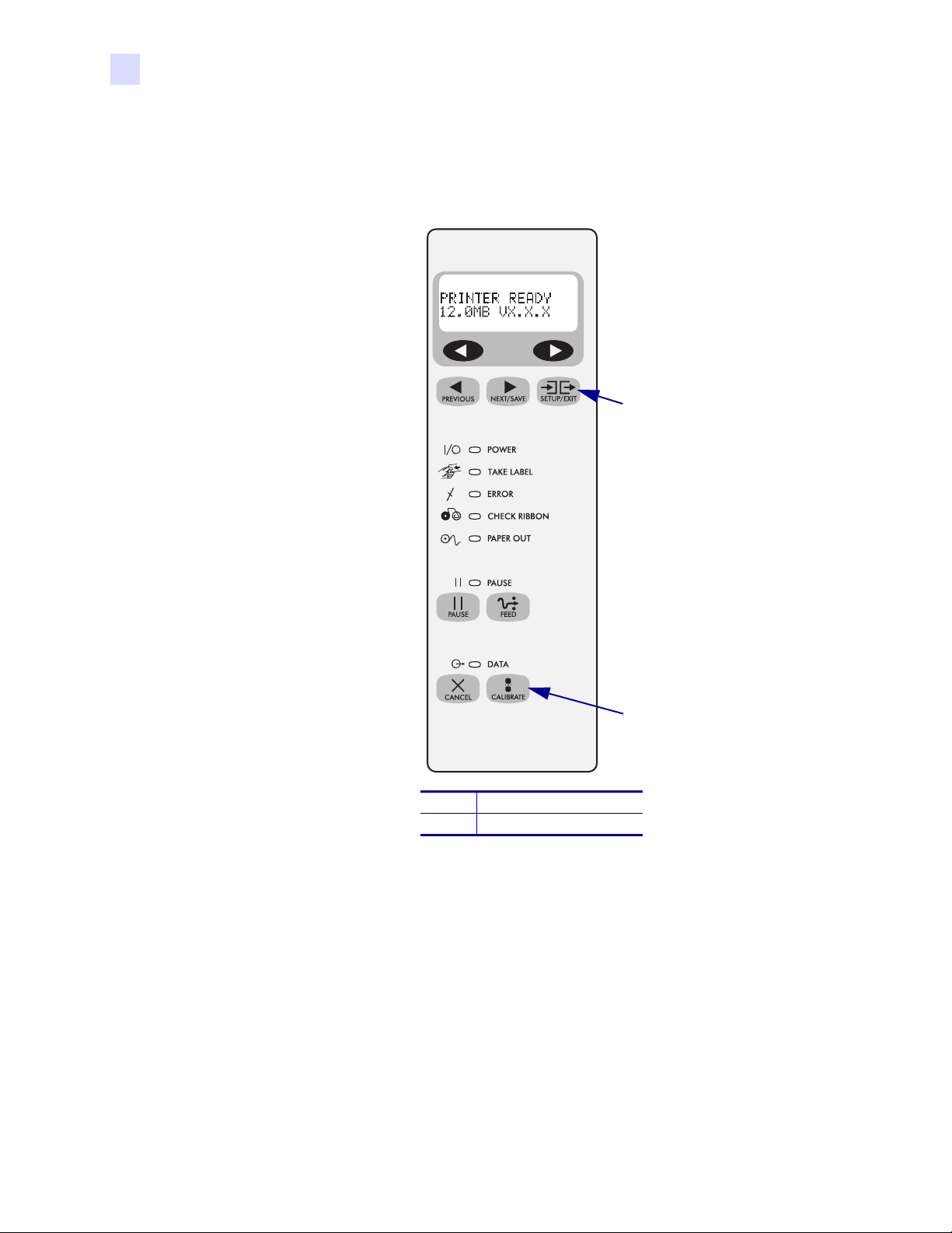
Illustration Callouts Callouts are used when an illustration contains information that needs
to be labeled and described. A table that contains the labels and descriptions follows the
graphic. Figure 1 provides an example.
Figure 1 • Sample Figure with Callouts
1
Related Documents
The following documents might be helpful references:
®
• ZPL II
number 45542L)
• ZebraNet
• Maintenance Manual (part number 48152L)
Programming Guide Volume I (part number 45541L) and Vol um e I I (part
®
PrintServer II™ Installation and User Guide (part number 45537L)
SETUP/EXIT button
1
CALIBRATE button
2
2
xii R110Xi/R170Xi User Guide 23063L-003 Rev. 2 12/23/04
Page 13

Introduction
This chapter provides a high-level overview of the printer and its components.
1
Contents
Exterior View . . . . . . . . . . . . . . . . . . . . . . . . . . . . . . . . . . . . . . . . . . . . . . . . . . . . . . . . . . . 2
Front Panel. . . . . . . . . . . . . . . . . . . . . . . . . . . . . . . . . . . . . . . . . . . . . . . . . . . . . . . . . . . . . 3
Front Panel Buttons . . . . . . . . . . . . . . . . . . . . . . . . . . . . . . . . . . . . . . . . . . . . . . . . . . . . 4
Front Panel Lights . . . . . . . . . . . . . . . . . . . . . . . . . . . . . . . . . . . . . . . . . . . . . . . . . . . . . 5
Printer Components . . . . . . . . . . . . . . . . . . . . . . . . . . . . . . . . . . . . . . . . . . . . . . . . . . . . . . 6
23063L-003 Rev. 2 12/23/04 R110Xi/R170Xi User Guide 1
Page 14
Introduction
Exterior View
Exterior View
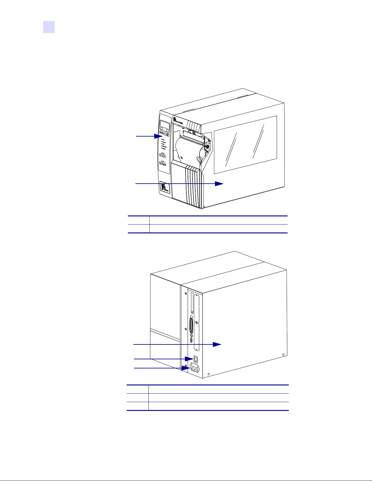
The following illustrations show the exterior of the printer.
Figure 2 • Printer Exterior—Front View
1
2
Front panel
1
Media door
2
Figure 3 • Printer Exterior—Rear View
1
2
3
Electronics cover
1
Power switch
2
AC power cord connection
3
2R110Xi/R170Xi User Guide 23063L-003 Rev. 2 12/23/04
Page 15
Front Panel
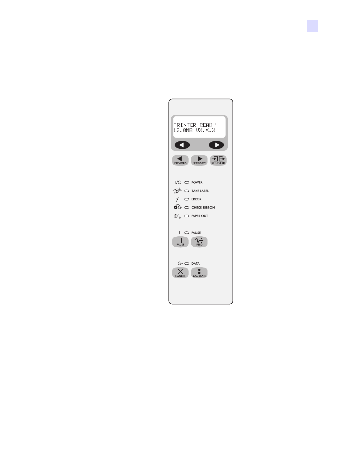
Figure 4 shows the buttons and lights on the front panel. For a description of the front panel
buttons, see Table 1 on page 4, and for a description of the front panel lights, see Tabl e 2
on page 5.
Introduction
Front Panel
Figure 4 • Front Panel Buttons and Lights
23063L-003 Rev. 2 12/23/04 R110Xi/R170Xi User Guide 3
Page 16
Introduction
Front Panel
Front Panel Buttons
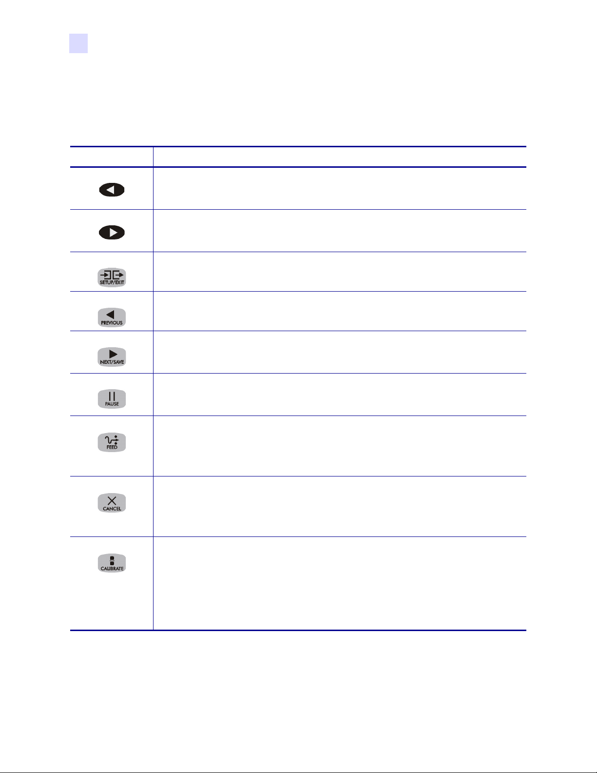
This table describes the function of the buttons shown in Figure 4.
Table 1 • Front Panel Buttons
Button Details
LEFT OVAL Changes parameter values. Common uses are to increase/decrease a value, answer yes or
no, indicate on or off, scroll through several choices, input the password, or set up the
printer for a firmware download.
RIGHT OVAL Changes parameter values. Common uses are to increase/decrease a value, answer yes or
no, indicate on or off, scroll through several choices, input the password, or set up the
printer for a firmware download.
SETUP/EXIT Enters and exits the setup mode.
PREVIOUS While in setup mode, scrolls to the previous parameter. Press and hold this button to
scroll back quickly through parameter sets.
NEXT/SAVE While in setup mode, scrolls to the next parameter. Press and hold this button to scroll
forward quickly through parameter sets. When exiting setup mode, this button scrolls
through the save options.
PAUSE Starts and stops the printing process and allows other buttons to be used. If an error
messages is on the LCD, pressing this button after the problem is resolved clears the error
and allows printing to resume.
FEED Forces the printer to feed a blank label each time the button is pressed.
• If the printer is not printing, one blank label immediately feeds.
• If the printer is printing, one blank label feeds after the current batch of labels is
complete.
CANCEL In the pause mode, this button cancels print jobs.
• If there are multiple print jobs in the print queue, press CANCEL once for each print
job to be deleted.
• To delete all print jobs, hold CANCEL for several seconds. The DATA light turns off.
CALIBRATE This button can be used to calibrate the printer for the following:
• Media length
• Media type (continuous or non-continuous)
• Print mode (direct thermal or thermal transfer)
• Sensor values
For more information on calibration, see Calibrate the Printer on page 35.
4R110Xi/R170Xi User Guide 23063L-003 Rev. 2 12/23/04
Page 17
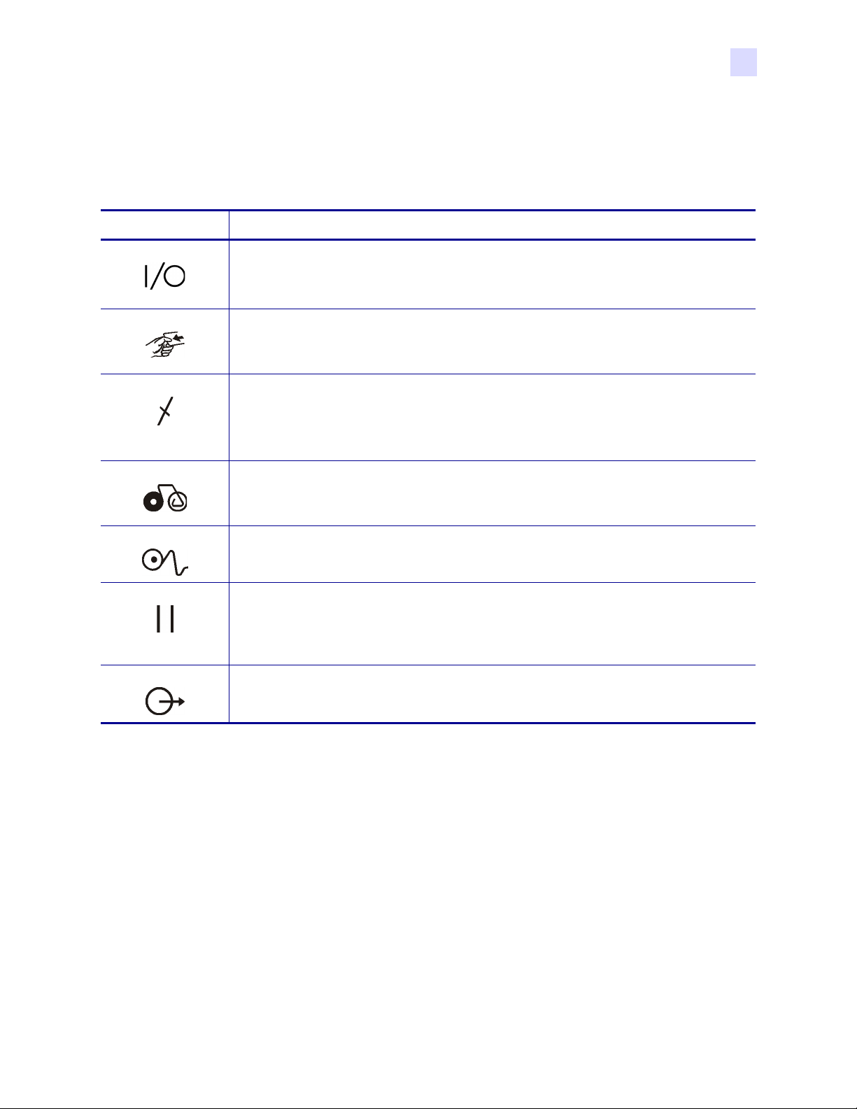
Front Panel Lights
This table details the lights shown in Figure 4 on page 3.
Table 2 • Front Panel Lights
Light Details
POWER Indicates printer power status.
• Off — printer is off.
• On — printer is on.
TAKE LABEL • Off — Normal operation.
• Flashing — (Peel-Off Mode only.) The label is available. Printing is paused until the
label is removed.
ERROR Indicates printer operation.
• Off — Normal operation.
• Flashing — printer pauses until the error condition is resolved and the PAUSE
button is pressed.
Introduction
Front Panel
CHECK RIBBON • Off — Normal operation; ribbon (if used) is properly loaded.
• On — No ribbon is detected under the ribbon sensor. Printing is paused, the LCD
shows an error message, and the PAUSE light is on.
PAPER OUT Indicates that labels need to be reloaded.
PAU SE • Off — normal operation.
• On — all printing operations have stopped. Either PAUSE was pressed, a pause
command was included in the label format, the on-line verifier detected an error, or a
printer error was detected.
DATA • Off — Normal operation. No data being received or processed.
• On/Blinking — Data processing or printing is taking place. Data is being received.
23063L-003 Rev. 2 12/23/04 R110Xi/R170Xi User Guide 5
Page 18
Introduction
Printer Components
Printer Components
Figure 5 shows a side view of the printer’s internal components.
Note • Depending on the printer options that you selected, your printer could look slightly
different. For more about printer options, go to www.zebra.com.
123
Figure 5 • Internal Components
4
7
11
10
9
Printhead lever
1
Ribbon take-up spindle
2
Ribbon supply spindle
3
Ribbon dancer assembly (only on select models)
4
Media guide
5
Media dancer roller assembly
6
Media supply guide
7
Media supply hanger
8
Lower roller
9
Platen roller
10
Tear- o ff b a r
11
5
8
6
6R110Xi/R170Xi User Guide 23063L-003 Rev. 2 12/23/04
Page 19

2
Printer Setup
This chapter provides the tasks that you must complete and the issues that you must consider
before you load and configure your printer.
Contents
Before You Begin . . . . . . . . . . . . . . . . . . . . . . . . . . . . . . . . . . . . . . . . . . . . . . . . . . . . . . . . 8
Unpack and Inspect the Printer . . . . . . . . . . . . . . . . . . . . . . . . . . . . . . . . . . . . . . . . . . . . . 9
Report Shipping Damage. . . . . . . . . . . . . . . . . . . . . . . . . . . . . . . . . . . . . . . . . . . . . . . . 9
Store or Reship the Printer. . . . . . . . . . . . . . . . . . . . . . . . . . . . . . . . . . . . . . . . . . . . . . . 9
Select a Site for the Printer . . . . . . . . . . . . . . . . . . . . . . . . . . . . . . . . . . . . . . . . . . . . . . . 10
Select a Surface. . . . . . . . . . . . . . . . . . . . . . . . . . . . . . . . . . . . . . . . . . . . . . . . . . . . . . 10
Provide Proper Operating Conditions . . . . . . . . . . . . . . . . . . . . . . . . . . . . . . . . . . . . . 10
Allow Proper Space . . . . . . . . . . . . . . . . . . . . . . . . . . . . . . . . . . . . . . . . . . . . . . . . . . . 10
Provide a Data Source. . . . . . . . . . . . . . . . . . . . . . . . . . . . . . . . . . . . . . . . . . . . . . . . . 10
Connect the Printer to a Power Source . . . . . . . . . . . . . . . . . . . . . . . . . . . . . . . . . . . . . . 11
Power Cord Specifications. . . . . . . . . . . . . . . . . . . . . . . . . . . . . . . . . . . . . . . . . . . . . . 11
Select a Communication Interface . . . . . . . . . . . . . . . . . . . . . . . . . . . . . . . . . . . . . . . . . . 12
Data Cable Requirements . . . . . . . . . . . . . . . . . . . . . . . . . . . . . . . . . . . . . . . . . . . . . . 13
Types of Media. . . . . . . . . . . . . . . . . . . . . . . . . . . . . . . . . . . . . . . . . . . . . . . . . . . . . . . . . 14
Ribbon . . . . . . . . . . . . . . . . . . . . . . . . . . . . . . . . . . . . . . . . . . . . . . . . . . . . . . . . . . . . . . . 16
When to Use Ribbon . . . . . . . . . . . . . . . . . . . . . . . . . . . . . . . . . . . . . . . . . . . . . . . . . . 16
Coated Side of Ribbon. . . . . . . . . . . . . . . . . . . . . . . . . . . . . . . . . . . . . . . . . . . . . . . . . 16
23063L-003 Rev. 2 12/23/04 R110Xi/R170Xi User Guide 7
Page 20

Printer Setup
Before You Begin
Before You Begin
Review this checklist, and resolve any issues before you begin setting up your printer. When
you are ready, continue with Printer Operation on page 19.
Unpack and Inspect Have you unpacked the printer and inspected it for damage? If
you have not, see Unpack and Inspect the Printer on page 9.
Select a Site Have you selected an appropriate location for the printer? If you have not,
see Select a Site for the Printer on page 10.
Attach Power Cord Do you have the correct power cord for your printer? If you are
unsure, see Power Cord Specifications on page 11. To attach the power cord and connect the
printer to a power source, see Connect the Printer to a Power Source on page 11.
Connect to a Data Source Have you determined how the printer will be connected to
a data source (usually a computer)? For more information, see Select a Communication
Interface on page 12.
Select Media Do you have the correct media for your application? If you are unsure,
see Types of Media on page 14.
Select Ribbon Do you need to use ribbon, and is the appropriate ribbon available, if
needed? If you are unsure, see Ribbon on page 16.
8R110Xi/R170Xi User Guide 23063L-003 Rev. 2 12/23/04
Page 21

Unpack and Inspect the Printer
When you unpack the printer, save all packing materials. When the printer is out of the box,
raise the printer’s media door, and remove the power cord.
Inspect the printer for possible damage incurred during shipment. Check all exterior surfaces
for damage. Raise the media door, and inspect the media compartment for damage to
components.
Report Shipping Damage
If you discover shipping damage upon inspection:
• Immediately notify the shipping company of the damage, and file a damage report with
them. Zebra is not responsible for any damage incurred during shipment of the equipment
and does not repair this damage under warranty.
• Keep all packaging material for shipping company inspection.
• Notify your authorized Zebra reseller.
Store or Reship the Printer
Printer Setup
Unpack and Inspect the Printer
If you are not placing the printer into immediate operation, repackage it using the original
packing materials. You may store the printer under the following conditions:
• Temperature: –40° to 140°F (–40° to 60°C)
• Relative humidity: 5% to 85% non-condensing
If you must ship the printer, remove any ribbon and media from the supply spools to avoid
damaging the printer. Carefully pack the printer into the original container or a suitable
alternate container to avoid damage during transit.
23063L-003 Rev. 2 12/23/04 R110Xi/R170Xi User Guide 9
Page 22
Printer Setup
Select a Site for the Printer
Select a Site for the Printer
Consider the following when selecting an appropriate location for your printer.
Select a Surface
Select a solid, level surface of sufficient size and strength to accommodate the printer and
other equipment (such as a computer), if necessary. The choices include a table, countertop,
desk, or cart.
Provide Proper Operating Conditions
Because the printer was designed and is fabricated as an industrial-type unit, it functions
satisfactorily in a location that conforms to specified environmental and electrical conditions,
including a warehouse or factory floor. For more information on the required conditions, see
General Specifications on page 142.
Table 3 shows the temperature and relative humidity requirements for the printer when it is
operating.
Table 3 • Operating Temperature and Humidity
Mode Temperature Relative Humidity
Thermal Transfer 41° to 104°F (5° to 40°C) 20 to 85% non-condensing
Direct Thermal 32° to 104°F (0° to 40°C) 20 to 85% non-condensing
Allow Proper Space
The printer should have enough space around it for you to be able to open the media door. To
allow for proper ventilation and cooling, leave open space on all sides of the printer.
Caution • Do not place any padding or cushioning material behind or under the printer
because this restricts air flow and could cause the printer to overheat.
Provide a Data Source
If the printer will be located away from the data source, the selected site must provide the
appropriate connections to that data source. For more information on the types of
communication interfaces, see Select a Communication Interface on page 12.
10 R110Xi/R170Xi User Guide 23063L-003 Rev. 2 12/23/04
Page 23

Connect the Printer to a Power Source
Connect the Printer to a Power Source
Caution • For personnel and equipment safety, always use an approved three-conductor
power cord specific to the region or country intended for installation. This cord must use
an IEC 320 female connector and the appropriate region-specific three-conductor
grounded plug configuration.
To connect the printer to a power source, complete these steps:
1. Turn the printer power switch (located on the rear of the printer) to the Off (O) position.
2. Plug the power cord into the mating connector on the rear of the printer.
3. Plug the other end of the power cord into the power source.
Power Cord Specifications
Depending on how your printer was ordered, a power cord may or may not be included. If one
is not included or if the one included is not suitable for your requirements, refer to the
following guidelines:
• The overall cord length must be less than 9.8 ft (3.0 m).
• The cord must be rated for at least 5 A, 250 V.
• The chassis ground (earth) must be connected to ensure safety and reduce electromagnetic
interference. The third wire in the power cord grounds the connection (Figure 6).
Printer Setup
Figure 6 • Power Cord Specifications
1 2 3 4
AC power plug for your country
1
3-conductor HAR cable
2
IEC 320 connector
3
Neutral, earth, live in contact view
4
• The AC power plug and the IEC 320 connector must bear the certification mark of at least
one of the known international safety organizations shown in Figure 7.
Figure 7 • International Safety Organization Marks
+
R
23063L-003 Rev. 2 12/23/04 R110Xi/R170Xi User Guide 11
Page 24
Printer Setup
Select a Communication Interface
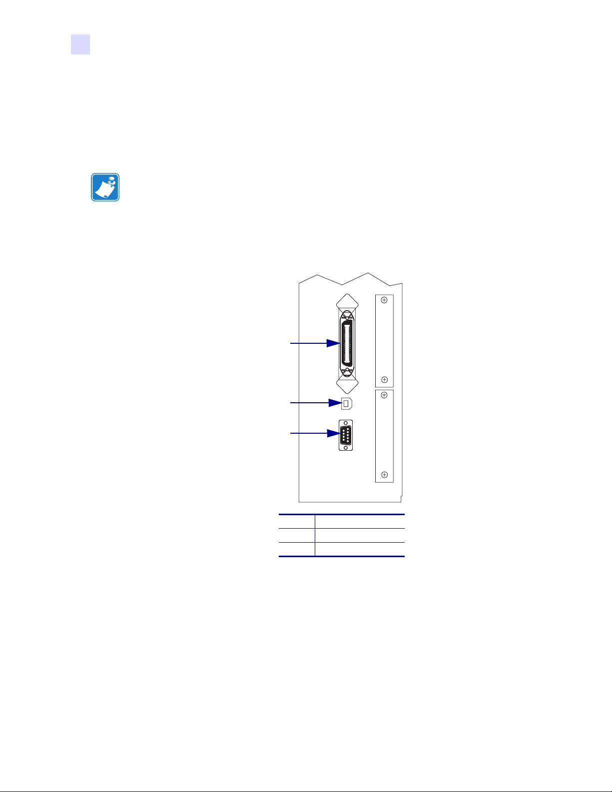
Select a Communication Interface
The way that you connect your printer to a data source depends on the communication options
installed in the printer.
Standard interfaces: The standard communication interfaces are an RS-232 serial data port, a
bidirectional parallel port, and a USB 2.0 port.
Note • RS-422 and RS-485 serial data ports are available through an adapter. A DB-25 cable
and a USB 2.0 cable are also available.
Figure 8 shows the location of the communication interfaces on the back of the printer. For
more information about these interfaces, see Data Ports on page 99.
Figure 8 • Communication Interfaces
1
2
3
Parallel port
1
USB 2.0 port
2
Serial port
3
Optional Print Servers:
• ZebraNet PrintServer II (PSII). For more information on PSII, see the PrintServer II User
and Reference Guide (Zebra part number 45537L).
12 R110Xi/R170Xi User Guide 23063L-003 Rev. 2 12/23/04
Page 25

Data Cable Requirements
Data cables must be fully shielded and fitted with metal or metallized connector shells.
Shielded cables and connectors are required to prevent radiation and reception of electrical
noise.
To minimize electrical noise pickup in the cable:
• Keep data cables as short as possible.
• Do not bundle the data cables tightly with the power cords.
• Do not tie the data cables to power wire conduits.
Note • Zebra printers comply with FCC Rules and Regulations, Part 15 for Class B Equipment
using fully shielded, 6.5 ft (2 m) data cables. Use of unshielded cables may increase radiation
above the Class B limits.
Note • RS-422 and RS-485 applications should use twisted shielded pairs as recommended in
the TIA/EIA-485 Specification.
Printer Setup
Select a Communication Interface
23063L-003 Rev. 2 12/23/04 R110Xi/R170Xi User Guide 13
Page 26
Printer Setup
Types of Media
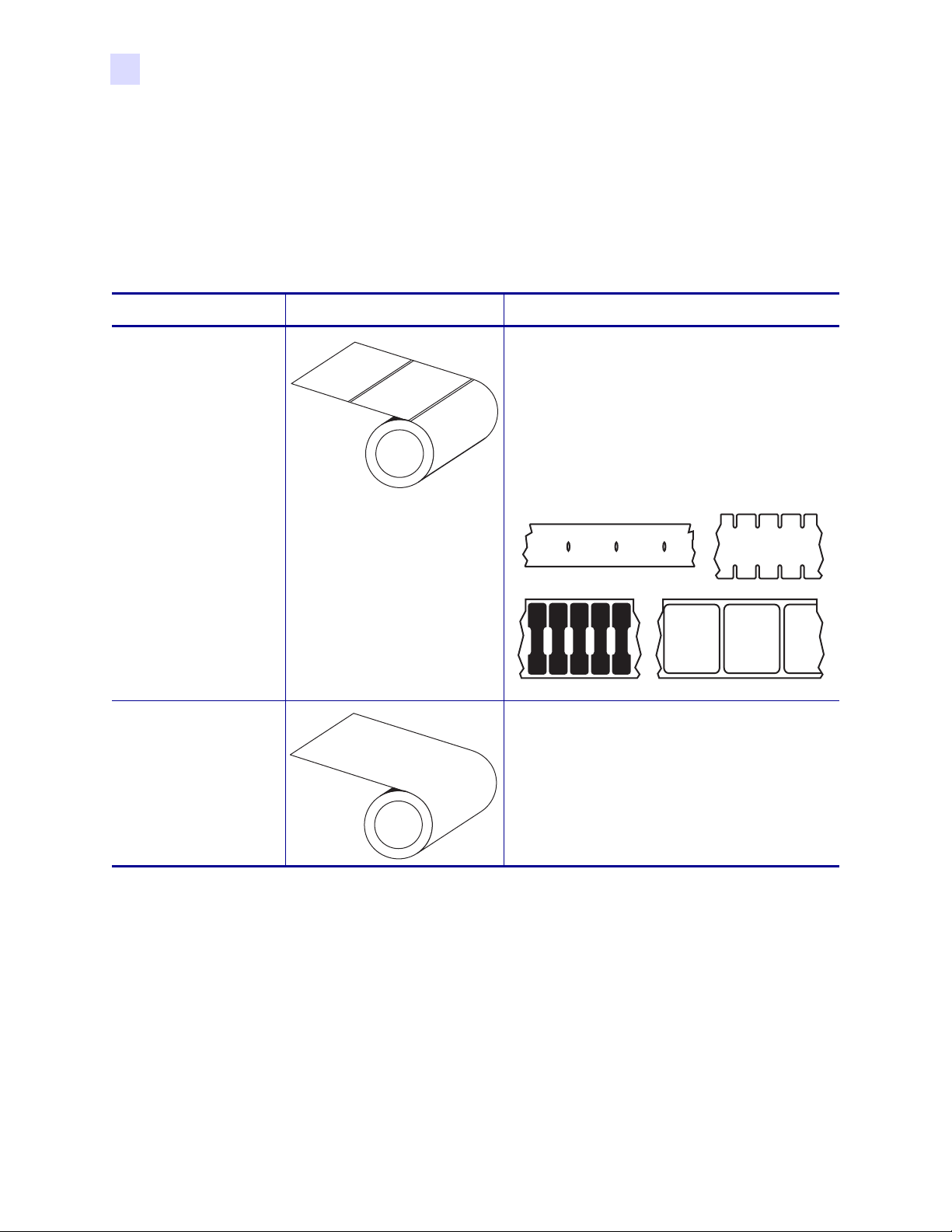
Types of Media
The printer can use various types of media (Table 4 ). We strongly recommend the use of
Zebra-brand supplies for continuous high-quality printing. A wide range of paper,
polypropylene, polyester, and vinyl stock has been specifically engineered to enhance the
printing capabilities of the printer and to ensure against premature printhead wear.
Table 4 • Types of Media
Media Type How It Looks Description
Non-Continuous
Roll Media
Continuous
Roll Media
The media is wound on a core. Individual labels
are separated by a gap, black mark, notch, or
hole, which enables you to see where one label
ends and the next one begins. When using media
that has holes or notches, position the media
sensor directly over a hole or notch. Figure 9
shows different types of non-continuous media.
Figure 9 • Non-Continuous Web Media
The media is wound on a core and is without
gaps, holes, notches, or black marks. This allows
the image to be printed anywhere on the label.
14 R110Xi/R170Xi User Guide 23063L-003 Rev. 2 12/23/04
Page 27
Printer Setup
Types of Media
Table 4 • Types of Media (Continued)
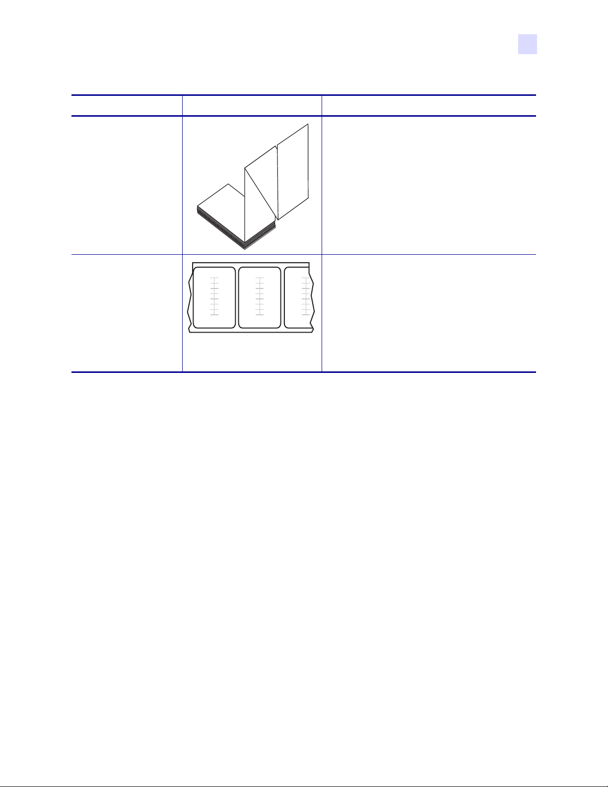
Media Type How It Looks Description
Fanfold Media The media is folded in a zigzag pattern.
RFID “Smart” Media Each label has a radio frequency identification
(RFID) chip and antenna inlay embedded
between the label and the liner. The media is
made from the same materials and adhesives as
non-RFID labels. The outline of the transponder
(which varies by manufacturer) can be seen
through the label. All “smart” labels have
memory that can be read, and many have
memory that can be encoded.
23063L-003 Rev. 2 12/23/04 R110Xi/R170Xi User Guide 15
Page 28
Printer Setup
Ribbon
Ribbon
Ribbon is a thin film that is coated on one side with wax, resin, or wax resin, which is
transferred to the media during the thermal transfer process. The media determines whether
you need to use ribbon and how wide the ribbon must be.
When ribbon is used, it must be as wide as or wider than the media being used. If the ribbon is
narrower than the media, areas of the printhead are unprotected and subject to premature wear.
When to Use Ribbon
Thermal transfer media requires ribbon for printing while direct thermal media does not.
To determine if ribbon must be used with a particular media, perform a media scratch test.
To perform a label scratch test, complete these steps:
1. Scratch the print surface of the media rapidly with your fingernail.
2. Did a black mark appear on the media?
If a black mark... Then the media is...
Does not appear on the media Thermal transfer. A ribbon is required.
Appears on the media Direct thermal. No ribbon is required.
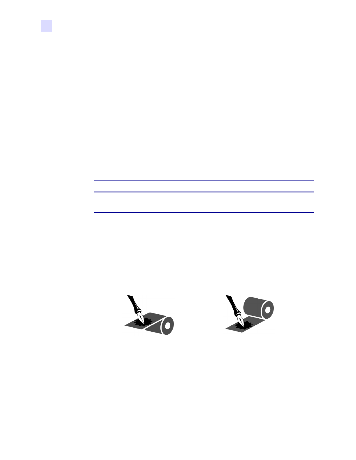
Coated Side of Ribbon
Ribbon can be wound with the coated side on the inside or outside (Figure 10). This printer
can only use ribbon that is coated on the outside. If you are unsure which side of a particular
roll of ribbon is coated, perform an adhesive test or a ribbon scratch test to determine which
side is coated.
Figure 10 • Ribbon Coated on Outside or Inside
Outside Inside
16 R110Xi/R170Xi User Guide 23063L-003 Rev. 2 12/23/04
Page 29

Adhesive Test
If you have labels available, perform the adhesive test to determine which side of a ribbon is
coated. This method works well for ribbon that is already installed.
To perform an adhesive test, complete these steps:
1. Peel a label from its liner.
2. Press a corner of the sticky side of the label to the outer surface of the roll of ribbon.
3. Peel the label off of the ribbon.
4. Observe the results. Did flakes or particles of ink from the ribbon adhere to the label?
If ink from the ribbon... Then...
Adhered to the label The ribbon is coated on the outer surface.
Printer Setup
Ribbon
Did not adhere to
the label
Ribbon Scratch Test
Perform the ribbon scratch test when labels are unavailable.
To perform a ribbon scratch test, complete these steps:
1. Unroll a short length of ribbon.
2. Place the unrolled section of ribbon on a piece of paper with the outer surface of the
ribbon in contact with the paper.
3. Scratch the inner surface of the unrolled ribbon with your fingernail.
4. Lift the ribbon from the paper.
5. Observe the results. Did the ribbon leave a mark on the paper?
If the ribbon... Then...
Left a mark on the paper The ribbon is coated on the outer surface.
Did not leave a mark on
the paper
The ribbon is coated on the inner surface. To verify this,
repeat the test on the inner surface of the roll of ribbon.
The ribbon is coated on the inner surface. To verify this,
repeat the test on the other surface of the roll of ribbon.
23063L-003 Rev. 2 12/23/04 R110Xi/R170Xi User Guide 17
Page 30

Printer Setup
Ribbon
Notes • ___________________________________________________________________
__________________________________________________________________________
__________________________________________________________________________
__________________________________________________________________________
__________________________________________________________________________
__________________________________________________________________________
__________________________________________________________________________
__________________________________________________________________________
__________________________________________________________________________
__________________________________________________________________________
18 R110Xi/R170Xi User Guide 23063L-003 Rev. 2 12/23/04
Page 31

3
Printer Operation
If you have completed the tasks and resolved the issues in the checklist in Before You Begin
on page 8, follow the instruction in this chapter to load and calibrate your printer and to print
configuration labels.
Contents
Loading the Media . . . . . . . . . . . . . . . . . . . . . . . . . . . . . . . . . . . . . . . . . . . . . . . . . . . . . . 20
Load Roll Media . . . . . . . . . . . . . . . . . . . . . . . . . . . . . . . . . . . . . . . . . . . . . . . . . . . . . . 21
Load Fanfold Media . . . . . . . . . . . . . . . . . . . . . . . . . . . . . . . . . . . . . . . . . . . . . . . . . . . 24
Loading Ribbon . . . . . . . . . . . . . . . . . . . . . . . . . . . . . . . . . . . . . . . . . . . . . . . . . . . . . . 26
Remove Used Ribbon . . . . . . . . . . . . . . . . . . . . . . . . . . . . . . . . . . . . . . . . . . . . . . . . . 31
Print a Printer Configuration Label. . . . . . . . . . . . . . . . . . . . . . . . . . . . . . . . . . . . . . . . . . 32
Print a Network Configuration Label . . . . . . . . . . . . . . . . . . . . . . . . . . . . . . . . . . . . . . . . 34
Calibrate the Printer . . . . . . . . . . . . . . . . . . . . . . . . . . . . . . . . . . . . . . . . . . . . . . . . . . . . . 35
Adjust Media Sensors . . . . . . . . . . . . . . . . . . . . . . . . . . . . . . . . . . . . . . . . . . . . . . . . . . . 37
Adjust Printhead Pressure and Toggle Position . . . . . . . . . . . . . . . . . . . . . . . . . . . . . . . . 39
Toggle Position Adjustment . . . . . . . . . . . . . . . . . . . . . . . . . . . . . . . . . . . . . . . . . . . . . 39
Printhead Pressure Adjustment . . . . . . . . . . . . . . . . . . . . . . . . . . . . . . . . . . . . . . . . . . 40
23063L-003 Rev. 2 12/23/04 R110Xi/R170Xi User Guide 19
Page 32

Printer Operation
Loading the Media
Loading the Media
This section gives you a series of instructions to load labels for a standard printer in Tear-Off
mode (Figure 11). You can use roll or fanfold media in this printer. For more information about
the types of media, see Types of Media on page 14.
• To load roll media, see Load Roll Media on page 21.
• To load fanfold media, see Load Fanfold Media on page 24.
Caution • Be sure the printer is Off (O) if you have connected the power cable.
Figure 11 • Printer Loaded in Tear-Off Mode
20 R110Xi/R170Xi User Guide 23063L-003 Rev. 2 12/23/04
Page 33

Load Roll Media
Roll media feeds through the printer from the media hanger or media supply spindle. Figure 12
identifies the components of the printer with which you need to be familiar to load roll media
in Tear-Off mode.
Figure 12 • Interior Components for Media Loading (Tear-Off Mode)
Printer Operation
Loading the Media
1
2
3
Printhead lever
1
Media guide
2
Media guide roller
3
Media guide on media hanger
4
Media hanger
5
4
5
23063L-003 Rev. 2 12/23/04 R110Xi/R170Xi User Guide 21
Page 34

Printer Operation
Loading the Media
To load roll media, complete these steps:
1. Open the printhead.
2. See Figure 13. Slide the media guide away from the printer frame. You may need to
loosen the media guide thumb screw.
Figure 13 • Adjusting the Media Guide
1
2
Media guide
1
Location of media guide thumb screw
2
Media guide on media hanger
3
Media hanger
4
3. Place the roll of media on the media hanger.
4. Push the media core toward the printer frame. Make sure that the labels are aligned with
3
4
the media core.
5. Adjust the media guide on the media hanger so it just touches but does not restrict the
media.
6. See Figure 14. Feed the media under the media guide roller and under the upper media
sensor assembly.
Important • Be sure to thread the media under the upper media sensor assembly and the
ribbon guide roller. If you thread the media over these, the media blocks the ribbon sensor.
22 R110Xi/R170Xi User Guide 23063L-003 Rev. 2 12/23/04
Page 35

Printer Operation
Loading the Media
Figure 14 • Threading Media
1
2
3
4
5
Ribbon guide roller
1
Upper media sensor assembly
2
Media guide roller
3
Media guide
4
Media
5
7. Pull the media through under the printhead.
8. Adjust the media guide so that it just touches but does not restrict the media. The labels
should lie flat.
9. Which type of media are you using?
If you are... Then...
Using direct thermal media Close the printhead, and then go to Print a Printer
Configuration Label on page 32.
Using thermal transfer media Go to Loading Ribbon on page 26.
Not sure Go to When to Use Ribbon on page 16.
23063L-003 Rev. 2 12/23/04 R110Xi/R170Xi User Guide 23
Page 36

Printer Operation
Loading the Media
Load Fanfold Media
Fanfold media feeds through either the bottom or rear access slot from outside the printer. The
media hanger and media supply spindle are not used with fanfold media.
To load fanfold labels, complete these steps:
1. Slide the printhead lever to the Open position.
2. See Figure 13 on page 22. Slide the media guide away from the printer frame. You may
need to loosen the media guide screw.
3. How do you want to feed the fanfold labels?
• From the bottom slot in the printer body.
Figure 15 shows the printer with fanfold labels loaded through the bottom slot.
Figure 15 • Fanfold Media—Bottom Loading
1
2
Printhead lever (shown in the Open position)
1
Media guide
2
Fanfold labels
3
3
24 R110Xi/R170Xi User Guide 23063L-003 Rev. 2 12/23/04
Page 37

Printer Operation
Loading the Media
• From the rear slot in the printer body.
Figure 16 shows the printer with fanfold labels loaded through the rear slot.
Figure 16 • Fanfold Media—Rear Loading
1
2
3
Printhead lever (shown in the Open position)
1
Media guide
2
Fanfold labels
3
4. See Figure 14 on page 23. Feed the media under the media guide roller and under the
upper media sensor assembly.
Important • Be sure to thread the media under the upper media sensor assembly and the
ribbon guide roller. If you thread the media over these, the media blocks the ribbon sensor.
5. Pull the media through under the printhead.
6. Adjust the media guide so that it just touches, but does not restrict, the edge of the media.
The labels should lie flat.
7. Which type of media are you using?
If you are... Then...
Using direct thermal
media
Using thermal transfer
Close the printhead, and then go to Print a Printer
Configuration Label on page 32.
Go to Loading Ribbon on page 26.
media
Not sure Go to When to Use Ribbon on page 16.
23063L-003 Rev. 2 12/23/04 R110Xi/R170Xi User Guide 25
Page 38

Printer Operation
Loading Ribbon
Loading Ribbon
Before you load ribbon, make sure that the media that you are using needs ribbon. Only
thermal transfer media requires ribbon. Ribbon is not required with direct thermal media,
though it may be used to protect the printhead from abrasion. For more information, see When
to Use Ribbon on page 16.
Caution • Use ribbon that is wider than the thermal transfer media. If the printhead is not
protected by the ribbon, the resulting abrasion from the media may cause premature
printhead wear.
Figure 17 shows the printer components that are mentioned in the ribbon loading procedure
and shows the path that the ribbon follows through the printer.
Figure 17 • Ribbon Path
1
2
3
8
7
64
Top roller
1
Ribbon take-up spindle
2
Ribbon supply spindle
3
Ribbon dancer assembly upper roller (only on some models)
4
Ribbon dancer assembly lower roller (only on some models)
5
Ribbon guide roller
6
Platen roller (not shown)
7
Printhead lever (shown in the Closed position)
8
5
26 R110Xi/R170Xi User Guide 23063L-003 Rev. 2 12/23/04
Page 39

Create a Ribbon Leader
A ribbon leader makes it easier to load and unload ribbon. Make a leader for your ribbon roll if
it does not already have one.
To make a ribbon leader, complete these steps:
1. Unroll the ribbon about 6 in. (15 cm).
2. Tear off a strip of labels and backing about 6 in. (15 cm) long from the label roll.
3. Peel a label from the backing.
4. Overlap the ribbon and the backing with the ribbon on top, and use the label to tape them
together. This serves as a ribbon leader (Figure 18).
Printer Operation
Loading Ribbon
Figure 18 • Ribbon Leader
Load Ribbon
To load the ribbon, complete these steps:
1. See Figure 19. Align the segments of the ribbon supply spindle.
2. Place the roll of ribbon on the ribbon supply spindle, and push the core as far back as it
can go.
3. If the printhead is closed, open it using the printhead lever.
Figure 19 • Ribbon Supply Spindle Segments
23063L-003 Rev. 2 12/23/04 R110Xi/R170Xi User Guide 27
Page 40

Printer Operation
Loading Ribbon
4. Does your printer contain a ribbon dancer assembly?
If... Then...
No See Figure 20. Thread the ribbon under the ribbon guide roller.
Figure 20 • Loading Ribbon, No Dancer Assembly
1
Ye s
Ribbon guide roller
1
a. See Figure 21. Thread the ribbon under the upper roller of the ribbon
dancer assembly and then over the lower roller.
b. Thread the ribbon under the ribbon guide roller.
Figure 21 • Loading Ribbon through the Dancer Assembly
1
2
3
Ribbon guide roller
1
Ribbon dancer assembly lower roller
2
Ribbon dancer assembly upper roller
3
28 R110Xi/R170Xi User Guide 23063L-003 Rev. 2 12/23/04
Page 41

Printer Operation
Loading Ribbon
5. See Figure 22. Thread the ribbon under the printhead and past the platen roller.
Figure 22 • Threading Ribbon Under the Printhead
1
2
3
4
Ribbon leader
1
Top roller
2
Printhead
3
Platen roller
4
6. Pull the ribbon leader over the printhead and above the top roller.
23063L-003 Rev. 2 12/23/04 R110Xi/R170Xi User Guide 29
Page 42

Printer Operation
Loading Ribbon
7. See Figure 23. Bring the ribbon under the ribbon take-up spindle, and wrap it around the
spindle counter-clockwise.
Figure 23 • Winding Ribbon around the Ribbon Take-up Spindle
1 2
Ribbon leader
1
Ribbon take-up spindle
2
8. Turn the ribbon take-up spindle counterclockwise until the ribbon stays on it, as shown.
9. Close the printhead.
30 R110Xi/R170Xi User Guide 23063L-003 Rev. 2 12/23/04
Page 43

Remove Used Ribbon
When the ribbon has run out or must be changed, remove the used ribbon from the take-up
spindle (Figure 24).
Figure 24 • Ribbon Take-Up Spindle
1 2
Used ribbon
1
Ribbon take-up spindle
2
Ribbon release bars
3
Notch in ribbon take-up spindle
4
Arrow on ribbon take-up spindle
5
Ribbon release knob
6
3
4
Printer Operation
Loading Ribbon
5
6
To remove used ribbon, complete these steps:
1. Open the printhead.
2. Has the ribbon run out?
If the ribbon... Then
Ran out Continue with the next step.
Did not run out Tear or cut the ribbon as close to the ribbon take-up spindle
as possible.
Caution • Do not cut through the ribbon that is on the
take-up spindle because you may damage the spindle.
Use the ribbon release knob to slide the ribbon off of the
spindle.
3. While holding the ribbon take-up spindle, turn the ribbon release knob clockwise until it
stops.
The ribbon release bars pivot down, easing the spindle’s grip on the used ribbon.
4. Slide the used ribbon off of the ribbon take-up spindle.
5. Align the arrow on the ribbon take-up spindle knob with the notch in the ribbon take-up
spindle.
23063L-003 Rev. 2 12/23/04 R110Xi/R170Xi User Guide 31
Page 44

Printer Operation
Print a Printer Configuration Label
Print a Printer Configuration Label
When you have loaded the media and ribbon (if necessary), print a configuration label as a
record of your printer’s current settings. Keep the label to use when troubleshooting printing
problems.
Caution • For personal and equipment safety, always use an approved three-conductor
power cord specific to the region or country intended for installation. This cord must use
an IEC 320 female connector and the appropriate region-specific three-conductor
grounded plug configuration.
To print a configuration label, complete these steps:
1. Connect the power cord to the power connection on the back of the printer.
2. To confirm the power connection, turn the printer On (I).
The printer performs the power-up self test (POST). When the test is complete,
READY
3. Does the front panel LCD display PRINTER READY?
displays on the front panel LCD.
PRINTER
If... Then...
Ye s Continue with the next step.
No Go to Troubleshooting on page 125.
4. Turn the printer Off (O).
5. Press and hold CANCEL while turning the printer On (I).
6. Release CANCEL when the DATA light turns off (approximately five seconds).
The configuration label prints (Figure 25).
7. Did the label print?
If a configuration
label...
Then...
Printed Connect the printer to your data source. Communication can be
handled in many different ways. More information about the
options is available in Select a Communication Interface
on page 12.
Did not print Sensors out of position is a common cause of printing problems.
Refer to Adjust Media Sensors on page 37. For additional
assistance, refer to Troubleshooting on page 125.
32 R110Xi/R170Xi User Guide 23063L-003 Rev. 2 12/23/04
Page 45

Print a Printer Configuration Label
Figure 25 • Printer Configuration Label
Printer Operation
23063L-003 Rev. 2 12/23/04 R110Xi/R170Xi User Guide 33
Page 46

Printer Operation
Print a Network Configuration Label
Print a Network Configuration Label
If you are using a print server, you can print a network configuration label after the printer is
connected to the network.
To print a network configuration label, complete these steps:
1. On the front panel, press SETUP/EXIT.
2. Use the left or right oval to scroll through the parameters until you reach LIST
NETWORK.
3. Press the right oval to confirm printing.
A network configuration label prints (Figure 26). An asterisk designates whether the
wired or wireless print server is active. If no wireless print server is installed, the wireless
portion of the label does not print.
Figure 26 • Network Configuration Label
asterisk
indicating
the active
print server
(With a Wireless Print Server Installed)
34 R110Xi/R170Xi User Guide 23063L-003 Rev. 2 12/23/04
Page 47

Printer Operation
Calibrate the Printer
Calibrate the Printer
Calibrate the printer when it is first put into service. Calibration allows the printer to establish
the proper settings for the specific media and ribbon used in your application. You may
calibrate the printer at other times as needed. Table 5 shows the different methods for
calibration.
Table 5 • Types of Calibration
Type of Calibration Description When/How It Occurs
Auto-calibration The printer automatically sets the
value it detects for the spaces
between labels.
Long (Standard)
Calibration
The printer does the following:
• feeds media and ribbon
• sets the values it detects for media
length, media type (continuous or
non-continuous), and print mode
(thermal transfer or direct thermal)
• updates the sensor values
Occurs at the following times:
• When the printer is first turned on
if CALIBRATION is selected for
MEDIA POWER UP (see Media
Power Up on page 54)
• When the printer feeds media after
the printhead is closed if
CALIBRATION is selected for
HEAD CLOSE (see Head Close
on page 54).
• As part of both the sensor profile
and media and ribbon sensor
calibration procedures.
To perform a long calibration, do one
of the following:
• Press
• Select CALIBRATION for the
PAUSE on the front panel to
pause the printer, and then press
CALIBRATE.
MEDIA POWER UP or HEAD
CLOSE parameter (see Media
Power Up on page 54 or Head
Close on page 54).
Short Calibration The printer calibrates using the
current sensor values rather than
detecting the spaces between labels
and resetting the sensors. This
calibration sequence uses fewer
labels than the long calibration
sequence, but it is less reliable
because the values that are stored in
the sensors could be incorrect.
23063L-003 Rev. 2 12/23/04 R110Xi/R170Xi User Guide 35
Select SHORT CAL for the
POWER UP or HEAD CLOSE
parameter (see Media Power Up
on page 54 or Head Close
on page 54).
MEDIA
Page 48

Printer Operation
Calibrate the Printer
Table 5 • Types of Calibration (Continued)
Type of Calibration Description When/How It Occurs
Sensor Profile
Calibration
Media and Ribbon
Sensor Sensitivity
Calibration
The printer auto-calibrates and prints
a media sensor profile.
One of the most common
adjustments to printer settings. The
printer resets the sensitivity of the
sensors to detect correctly the media
and ribbon that you are using. If you
change the type of ribbon and/or
media, you might need to reset the
sensitivity of the media and ribbon
sensors. When the sensors are at their
new sensitivity, the printer performs
an auto-calibration.
Select the SENSOR PROFILE
option on the front panel. See Sensor
Profile on page 49 for instructions.
Select the
CALIBRATE
MEDIA AND RIBBON
option on the front
panel. See Calibrate Media and
Ribbon Sensors on page 50 for
instructions.
36 R110Xi/R170Xi User Guide 23063L-003 Rev. 2 12/23/04
Page 49

Adjust Media Sensors
The transmissive sensor consists of two sections: a light source (the lower media sensor) and a
light sensor (the upper media sensor). The media passes between the two.
Adjust these sensors only when the printer cannot detect the top of the label. The front panel
LCD displays
the printer.
Note • The upper media sensor can be positioned along the inside half of the media (the side
closest to the back of the printer) or the outside half of the media (the side farthest from the
back of the printer).
To adjust the upper media sensor for the inside half of the media, complete
these steps:
1. Remove the ribbon (if ribbon is used).
2. Locate the upper media sensor (Figure 27). The upper media sensor eye is directly below
the adjustment screw head.
ERROR CONDITION PAPER OUT, even though there are labels loaded in
Printer Operation
Adjust Media Sensors
Figure 27 • Upper Media Sensor Location
1
Upper media sensor adjustment screw
1
Upper media sensor
2
3. Using a Phillips-head screwdriver, slightly loosen the upper media sensor adjustment
2
screw.
4. Using the tip of the screwdriver, slide the upper sensor along the slot to the desired
position (for non-continuous media with a notch or hole in the media, the sensor must be
directly above the notch or hole).
5. Tighten the adjustment screw to secure the upper media sensor.
23063L-003 Rev. 2 12/23/04 R110Xi/R170Xi User Guide 37
Page 50

Printer Operation
Adjust Media Sensors
To adjust the upper media sensor for the outside half of the media:
1. Remove the ribbon (if ribbon is used).
2. Locate the upper media sensor. The upper media sensor eye is directly below the
adjustment screw head.
3. Using a Phillips-head screwdriver, remove the upper media sensor adjustment screw.
4. Lift the upper media sensor assembly from the slot, and move it and the wire cover to the
outside slot. Carefully pull the wires through the cable tie. You may need to set aside the
sensor wire cover if the adjustment is too far to the outside.
5. Replace and slightly tighten the adjustment screw.
6. Slide the upper media sensor along the slot to the desired position (for non-continuous
media with a notch or hole in the media, the sensor must be directly above the notch or
hole).
7. Tighten the adjustment screw.
8. Make sure that the wires are routed back into the groove of the media sensor bracket.
To adjust the lower media sensor, complete these steps:
1. Locate the lower media sensor assembly under the rear roller (Figure 28). The sensor is a
spring clip holding a circuit board.
Figure 28 • Lower Media Sensor Location
1
Lower media sensor
1
2. Slide the lower sensor until it is under the upper media sensor. Gently pull wires out as
needed (wires should have a little slack).
3. If you move the sensor inward and a large loop of wire develops, remove the electronics
cover from the side of the printer, and gently pull the wires through. Clamp the wires so
that they do not touch any drive belts.
38 R110Xi/R170Xi User Guide 23063L-003 Rev. 2 12/23/04
Page 51

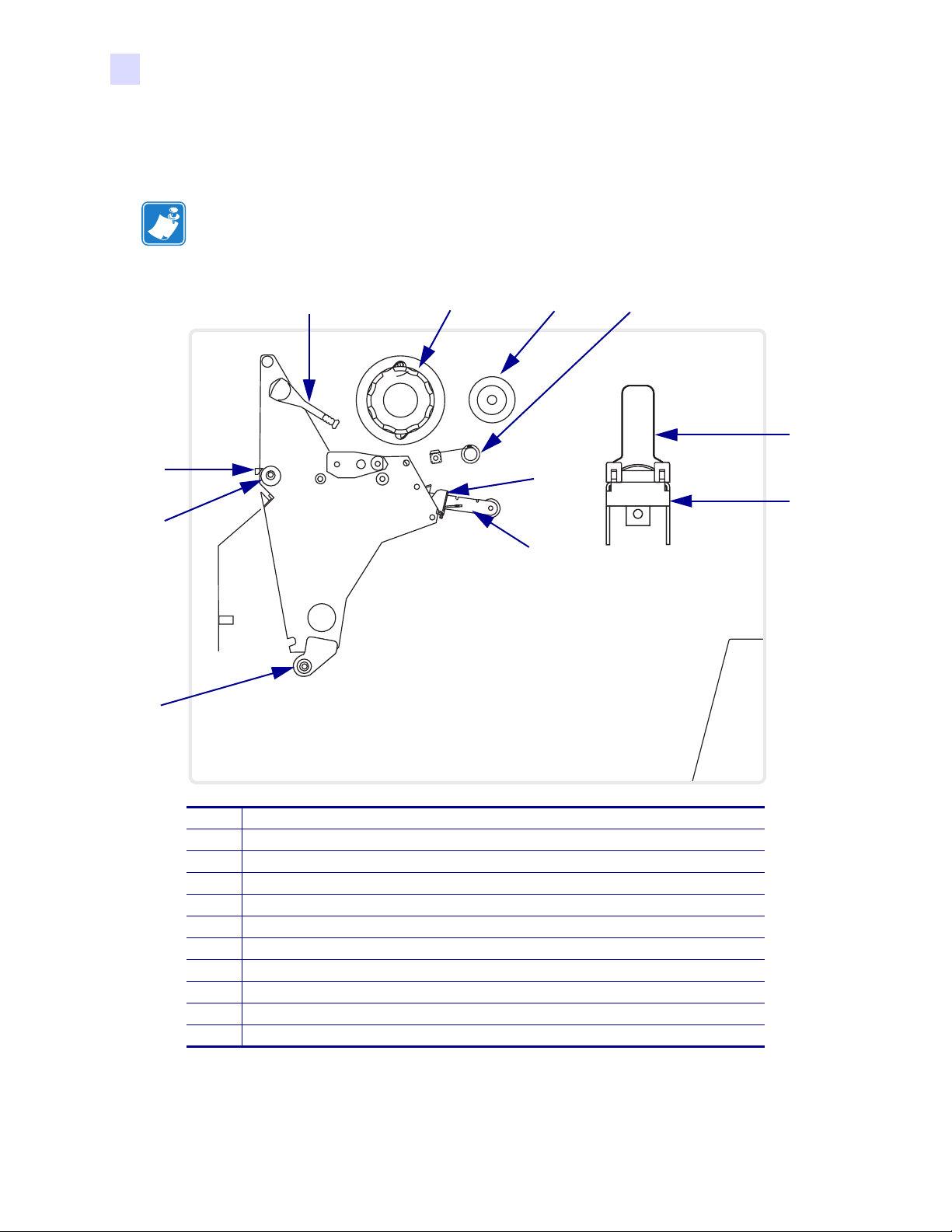
Adjust Printhead Pressure and Toggle Position
Adjust Printhead Pressure and Toggle Position
Printhead pressure is one factor that affects print quality. If the toggle pressure is too light or
uneven, the labels and ribbon may slip.
Important • Print quality depends on the labels and ribbon used as well as the toggle pressure.
Make sure that your labels and ribbon are right for your application.
• Direct thermal media does not need ribbon.
• Thermal transfer media needs ribbon.
Toggle Position Adjustment
You may need to adjust the toggles if printing is too light on one side or if thick labels are used.
To position the toggles, complete these steps:
1. Loosen the locking nuts at the top of the toggle assemblies (Figure 30).
Figure 29 • Adjusting Toggle Assembly Positions
1
Printer Operation
Locking nuts
1
2. Slide the toggles until they provide even pressure on the media. For extremely narrow
media, position one toggle over the center of the labels, and decrease the pressure on the
unused toggle.
3. Tighten the locking nuts.
23063L-003 Rev. 2 12/23/04 R110Xi/R170Xi User Guide 39
Page 52

Printer Operation
Adjust Printhead Pressure and Toggle Position
Printhead Pressure Adjustment
If positioning the toggles properly does not solve the problem, adjust printhead pressure.
Maximize printhead life by using the lowest pressure that produces the desired print quality.
Caution • Observe proper electrostatic safety precautions when handling any staticsensitive components such as circuit boards and printheads.
To adjust printhead pressure, complete these steps:
1. Print some labels at 2.4 in. (61 mm) per second by running the PA U S E S e l f Te s t
on page 136.
2. While printing labels, use the front panel controls to lower the darkness setting until the
labels are printing gray instead of black.
3. Loosen the upper knurled nuts on the toggle assemblies (Figure 30).
Figure 30 • Adjusting Printhead Pressure
1
2
Upper knurled nuts
1
Lower knurled nuts
2
4. Some media types require higher pressure to print well. For these media types, increase or
decrease pressure using the lower knurled nuts until the left and right edges of the printed
area are equally dark.
5. Increase the darkness level using the front panel controls until the printing is clear.
6. Tighten the upper knurled nuts.
40 R110Xi/R170Xi User Guide 23063L-003 Rev. 2 12/23/04
Page 53

Front Panel Controls
This chapter describes the function of the front panel.
4
Contents
Overview . . . . . . . . . . . . . . . . . . . . . . . . . . . . . . . . . . . . . . . . . . . . . . . . . . . . . . . . . . . . . 42
Enter Setup Mode . . . . . . . . . . . . . . . . . . . . . . . . . . . . . . . . . . . . . . . . . . . . . . . . . . . . 42
Exit Setup Mode. . . . . . . . . . . . . . . . . . . . . . . . . . . . . . . . . . . . . . . . . . . . . . . . . . . . . . 42
Password-Protected Parameters . . . . . . . . . . . . . . . . . . . . . . . . . . . . . . . . . . . . . . . . . . . 43
Default Password Value. . . . . . . . . . . . . . . . . . . . . . . . . . . . . . . . . . . . . . . . . . . . . . . . 43
Disable the Password Protection Feature . . . . . . . . . . . . . . . . . . . . . . . . . . . . . . . . . . 43
Front Panel LCD . . . . . . . . . . . . . . . . . . . . . . . . . . . . . . . . . . . . . . . . . . . . . . . . . . . . . . . 44
ZebraNet
RFID LCD Displays . . . . . . . . . . . . . . . . . . . . . . . . . . . . . . . . . . . . . . . . . . . . . . . . . . . 62
®
Wired and Wireless Print Server LCD Displays . . . . . . . . . . . . . . . . . . . . . 60
23063L-003 Rev. 2 12/23/04 R110Xi/R170Xi User Guide 41
Page 54

Front Panel Controls
Overview
Overview
After you have installed media and ribbon and printed a configuration label, you can change
the printer’s settings using the front panel controls. For an overview of the front panel,
including descriptions of the buttons and lights, see Front Panel on page 3. If you need to
restore the printer to its factory default settings, see FEED and PAUSE Self Test on page 138.
Many printer settings may be controlled by your printer’s driver or label preparation software.
Refer to the driver or software documentation for more information.
Enter Setup Mode
To enter Setup Mode, complete these steps:
1. Press SETUP/EXIT to enter Setup Mode.
2. Press either NEXT/SAVE or PREVIOUS to scroll through the parameters.
Exit Setup Mode
To leave Setup Mode, complete these steps:
1. Press SETUP/EXIT.
The LCD displays
2. Press the left or right oval to display the save options (Table 6).
Table 6 • Save Options When Leaving Setup Mode
LCD Display Description
PERMANENT
TEMPORARY
CANCEL
LOAD DEFAULTS
LOAD LAST SAVE
DEFAULT NET
Permanently saves the changes. Values are stored in the printer even when
power is turned off.
Saves the changes until you change them again or until power is turned off.
Cancels all changes from the time you pressed SETUP/EXIT except the
darkness and tear-off settings (if they were changed).
Sets all parameters other than the network settings back to the factory defaults.
To see the factory default values, see Front Panel LCD on page 44.
Note • Loading factory defaults causes the printer to auto-calibrate.
Loads values from the last permanent save.
Sets the wired and wireless network settings back to factory defaults.
SAVE CHANGES.
3. Press NEXT/SAVE to select the displayed choice.
When the configuration and calibration sequence is done,
42 R110Xi/R170Xi User Guide 23063L-003 Rev. 2 12/23/04
PRINTER READY displays.
Page 55

Password-Protected Parameters
Certain parameters are password-protected by factory default, including the communication
parameters.
Note • If the parameters are set incorrectly, the printer may function unpredictably.
The first attempt to change a password-protected parameter (pressing one of the ovals)
requires you to enter a four-digit password at the
changes the selected digit position; the right oval increases the selected digit value. After
entering the password, press
If the password was entered correctly, you can now change the value.
The first time that you attempt to change a password-protected parameter, the printer displays
ENTER PASSWORD. Before you can change the parameter, you must enter the four-digit
password. After you have entered the password correctly, you do not have to enter it again
unless you leave Setup Mode by pressing
To Enter a Password for a Password-Protected Parameter, complete
these steps:
NEXT/SAVE. The parameter you wish to change is displayed.
Front Panel Controls
Password-Protected Parameters
ENTER PASSWORD display. The left oval
SETUP/EXIT or by turning the printer Off (O).
1. At the password prompt, use the left oval to change the selected digit position.
2. When you have selected the digit that you wish to change, use the right oval to increase
the selected digit value. Repeat these two steps for each digit of the password.
3. After entering the password, press NEXT/SAVE.
The parameter you selected to change is displayed. If the password was entered correctly,
you can change the value.
Default Password Value
The default password value is 1234. The password can be changed using the ^KP (Define
Password) ZPL II instruction or through ZebraLink
required).
Disable the Password Protection Feature
You can disable the password protection feature so that it no longer prompts you for a
password. To do this, set the password to 0000 by sending the ZPL/ZPL II command ^KPØ to
the printer. To reenable the password-protection feature, send the command ^KPx, where x
can be any number from 1 to 9999.
™
WebVi ew ( Zeb r aNe t®PrintServer II
23063L-003 Rev. 2 12/23/04 R110Xi/R170Xi User Guide 43
Page 56

Front Panel Controls
Front Panel LCD
Front Panel LCD
Use the LCD display on the front panel to adjust printer settings. The tables in this section
show parameters in the order in which they are displayed when you press
entering setup mode. Throughout this process, press
parameter, or press
Standard LCD Displays
Table 7 lists the standard parameters displayed on all models of this printer. Additional
parameters may appear when different options are installed in the printer. See
ZebraNet
Displays on page 62 for more parameters.
Parameter Action/Explanation
®
Wired and Wireless Print Server LCD Displays on page 60 and RFID LCD
Table 7 • Standard LCD Displays (Page 1 of 16)
PREVIOUS to return to the previous parameter in the cycle.
NEXT/SAVE after
NEXT/SAVE to continue to the next
DARKNESS
PRINT SPEED
Adjusting Print Darkness
Darkness settings depend on a variety of factors, including ribbon type, labels, and
the condition of the printhead. You may adjust the darkness for consistent highquality printing.
If printing is too light, or if there are voids in printed areas, you should increase the
darkness. If printing is too dark, or if there is spreading or bleeding of printed areas,
you should decrease the darkness. Darkness settings also may be changed by the
driver or software settings.
The FEED Self Test described in FEED Self Test on page 137 can also be used to
determine the best darkness setting. Because the darkness setting takes effect
immediately, you can see the results on labels that are currently printing.
Important • Set the darkness to the lowest setting that provides good print quality.
If the darkness is set too high, the ink may smear, the ribbon may burn through, or
the printhead may wear prematurely.
• Press the right oval to increase darkness.
• Press the left oval to decrease darkness.
Default: +4
Range: 0 to +30.0
Adjusting Print Speed
Slower print speeds typically yield better print quality. Print speed changes take
effect upon exiting the menu mode.
• Press the right oval to increase print speed.
• Press the left oval to decrease print speed.
Default: 2 ips
Range: 2 ips to +12 ips (depends on specific printer)
44 R110Xi/R170Xi User Guide 23063L-003 Rev. 2 12/23/04
Page 57

Table 7 • Standard LCD Displays (Page 2 of 16)
Parameter Action/Explanation
Front Panel Controls
Front Panel LCD
TEAR OFF
PRINT MODE
MEDIA TYPE
Adjusting the Tear-Off Position
This parameter establishes the position of the labels over the tear-off/peel-off bar
after printing.
Each press of an oval adjusts the tear-off position by four dot rows.
• Press the right oval to increase value.
• Press the left oval to decrease value.
Default: +0
Range: –120 to +120
Selecting Print Mode
Print mode settings tell the printer the method of label delivery that you wish to use.
Be sure to select a print mode that your hardware configuration supports because
some of the selections displayed are for optional printer features.
• Press either oval to display choices.
Default: Tear- O ff
Selections: Tear-Off, Peel-Off, Cutter, Applicator, Rewind
Note • Only Tear-Off mode is supported.
Setting Media Type
This parameter tells the printer the type of media that you are using. Selecting
continuous media requires that you include a label length instruction in your label
format (
When non-continuous media is selected, the printer feeds media to calculate label
length (the distance between two recognized registration points of the inter-label
gap, webbing, or alignment notch or hole).
• Press either oval to display choices.
Default: Non-Continuous
Selections: Continuous, Non-Continuous
^LLxxxx if you are using ZPL or ZPL II).
SENSOR TYPE
23063L-003 Rev. 2 12/23/04 R110Xi/R170Xi User Guide 45
Setting the Sensor Type
This parameter tells the printer whether you are using media with a web (gap/space
between labels, notch, or hole) to indicate the separations between labels or if you
are using media with a black mark printed on the back. If your media does not have
black marks for registration on the back, leave your printer at the default (web).
• Press either oval to display other choices.
Default: WEB
Selections: WEB, MARK
Page 58

Front Panel Controls
Front Panel LCD
Table 7 • Standard LCD Displays (Page 3 of 16)
Parameter Action/Explanation
PRINT METHOD
PRINT WIDTH
Selecting Print Method
The print method parameter tells the printer the method of printing that you wish to
use: direct thermal (no ribbon) or thermal transfer (using thermal transfer media and
ribbon).
• Press either oval to display choices.
Default: THERMAL-TRANS.
Selections: THERMAL-TRANS., DIRECT-THERMAL
Note • Selecting direct thermal when using thermal transfer media and ribbon
creates a printer error condition, but printing continues.
Setting Print Width
Print width determines the printable area across the width of the label.
To change value shown:
1. Press the left oval to move the cursor.
2. Press the right oval to increase the value of the digit.
Note • The printer does not accept any value larger than the maximum print width
listed in General Specifications on page 142.
To change the unit of measurement:
a. Press the left oval until the unit of measurement is active.
b. Press the right oval to toggle to a different unit of measure (mm, inches,
or dots).
Default Range:
The default and range of acceptable values vary depending on the
printer. See General Specifications on page 142 for further information about the
ranges available for your model.
MAXIMUM LENGTH
Setting Maximum Length
Maximum length is used in conjunction with the calibration procedure. The value
of this setting is the maximum label length that is used during the media portion of
the calibration process. Only a few labels are required to set media sensors. Always
set the value that is at least 1 in. (25.4 mm) longer than the longest label to be used
on the printer.
• To increase the value, press the right oval.
• To decrease the value, press the left oval.
Default Range:
The default and range of acceptable values vary depending on your
printer’s configuration. Values are adjustable in 1 in. (25.4 mm) increments.
46 R110Xi/R170Xi User Guide 23063L-003 Rev. 2 12/23/04
Page 59

Table 7 • Standard LCD Displays (Page 4 of 16)
Parameter Action/Explanation
Front Panel Controls
Front Panel LCD
EARLY WARNING
Setting Early Warning
When this parameter is enabled, the printer provides warnings when labels or
ribbons are running low or when the printhead needs to be cleaned.
Note • Labels per roll and ribbon length need to be updated when beginning use of
the Early Warning System. Also, the printer does not make any adjustments when
power is turned off and on.
• Press the right or left oval to display other choices.
Default: MEDIA DISABLED, MAINTENANCE OFF
Selections: MEDIA DISABLED, MEDIA ENABLED, MAINTENANCE OFF,
MAINTENANCE ON
To change the Early Warning settings,
1. When the LCD displays EARLY WARNING, press the right or left oval until
the desired setting is listed on the LCD. (If you are prompted for a password,
enter your password using the instructions in Password-Protected Parameters
on page 43.)
2. Press NEXT/SAVE to access the next early warning option.
3. Repeat this process to set the early warning for ribbon or maintenance
(printhead cleaning).
When the printer detects that less than 15% of the labels or ribbon remain,
WARNING MEDIA LOW appears on the LCD. If the alert function has been
enabled, an alert is also sent. When the printhead is opened then closed after a
media or ribbon warning has been received, the LCD prompts with
REPLACED?
. Press the right oval to select YES to clear the warning and reset
the label counter.
When setting the Early Warning for maintenance, the LCD prompts
CLEAN?
4. Press the right oval to select YES.
5. Press SETUP/EXIT to exit setup mode.
6. Press NEXT/SAVE to save changes.
.
MEDIA
HEAD
LABELS PER ROLL
Setting Labels Per Roll
This parameter needs to be updated when setting the Early Warning System so the
printer can provide early warnings when labels are running low.
• Press the right or left oval to display other choices.
Default: 900 labels
Range: 100 labels to 9999 labels
LIST FONTS
List Fonts
• Press the right oval to print a label that lists the available fonts in the printer,
including standard printer fonts plus any optional fonts. Fonts may be stored in
RAM, Flash memory, font EPROMs, or font cards.
LIST BAR CODES
List Bar Codes
• Press the right oval to print a label that lists the available bar codes in the printer.
23063L-003 Rev. 2 12/23/04 R110Xi/R170Xi User Guide 47
Page 60

Front Panel Controls
Front Panel LCD
Table 7 • Standard LCD Displays (Page 5 of 16)
Parameter Action/Explanation
LIST IMAGES
LIST FORMATS
LIST SETUP
LIST NETWORK
LIST ALL
FORMAT CARD
A: B:
List Images
• Press the right oval to print a label that lists the available images stored in the
printer’s RAM, Flash memory, optional EPROM, or optional memory card.
List Formats
• Press the right oval to print a label that lists the available formats stored in the
printer’s RAM, Flash memory, optional EPROM, or optional memory card.
List Setup
• Press the right oval to print a label that lists the current printer configuration.
(Same label as shown in Print a Printer Configuration Label on page 32.)
List Network Settings
This selection is used to print a network configuration label, which lists the settings
for the wired ZebraNet PrintServer II (PSII) and the ZebraNet Wireless Print Server
(if installed).
• Press the right oval to print a label that lists the current network configuration.
(Same label as shown in Print a Network Configuration Label on page 34.)
List All
• Press the right oval to print labels that list the available fonts, bar codes, images,
formats, and the current printer and network configurations.
Format Memory Card
Caution • Perform this operation only when it is necessary to erase all
previously stored information from the memory card.
1. When the LCD displays INITIALIZE CARD, press the left oval to select the
A memory (internal CompactFlash) or the right oval to select B memory
(PCMCIA card). (If you are prompted for a password, enter your password
using the instructions in Password-Protected Parameters on page 43.)
The front panel LCD asks
2. Do you wish to continue?
• Press the left oval to select NO to cancel the request and return to
ARE YOU SURE?.
INITIALIZE CARD prompt.
• Press the right oval to select
YES and begin initialization.
FORMATTING CARD displays.
When formatting is complete,
Note • Depending on the amount of memory in the memory card, initialization may
take up to three minutes to complete.
INITIALIZE CARD displays.
48 R110Xi/R170Xi User Guide 23063L-003 Rev. 2 12/23/04
Page 61

Table 7 • Standard LCD Displays (Page 6 of 16)
Parameter Action/Explanation
Front Panel Controls
Front Panel LCD
INIT FLASH MEM
SENSOR PROFILE
Initialize Flash Memory
Caution • Perform this operation only when it is necessary to erase all
previously stored information from Flash memory.
1. When the LCD displays INITIALIZE CARD, press the right oval to select
YES. (If you are prompted for a password, enter your password using the
instructions in Password-Protected Parameters on page 43.)
The LCD asks
2. Press the right oval to select YES.
The LCD asks ARE YOU SURE?.
3. Do you wish to continue?
• Press the left oval to select
FLASH MEM
• Press the right oval to select
When formatting is complete,
Sensor Profile
The media sensor profile may be used to troubleshoot registration problems that
may be caused when the media sensor detects preprinted areas on the media or
experiences difficulty in determining web location.
• Press the right oval to start this standard calibration procedure and print a media
sensor profile.
Figure 31 shows a media sensor profile. If the sensitivity of the media and/or ribbon
sensors must be adjusted, use Calibrate Media and Ribbon Sensors on page 50 to
adjust the media and ribbon sensor sensitivity.
INITIALIZE FLASH.
NO to cancel the request and return to the INIT
prompt.
YES and begin initialization.
INIT FLASH MEM displays.
Figure 31 • Media Sensor Profile
23063L-003 Rev. 2 12/23/04 R110Xi/R170Xi User Guide 49
Page 62

Front Panel Controls
Front Panel LCD
Table 7 • Standard LCD Displays (Page 7 of 16)
Parameter Action/Explanation
MEDIA AND
RIBBON
CALIBRATE
Calibrate Media and Ribbon Sensors
Use this procedure to adjust sensitivity of media and ribbon sensors.
Important • This procedure must be followed exactly as presented. All of the steps
must be performed even if only one of the sensors requires adjustment. You may
press the left oval at any step in this procedure to cancel the procedure.
1. Press the right oval to start the calibration procedure.
LOAD BACKING prompt displays.
The
2. Open the printhead.
3. Remove approximately 8 in. (203 mm) of labels from the backing, and pull the
media into the printer so that only the backing is between the media sensors.
4. Leave the printhead open.
5. Press the right oval to continue.
REMOVE RIBBON prompt displays.
The
6. Remove the ribbon.
7. Close the printhead.
8. Press the right oval to continue.
The message
CALIBRATING PLEASE WAIT displays.
The printer adjusts the scale (gain) of the signals that it receives from the media
and ribbon sensors. On the sensor profile, this essentially corresponds to moving
the peak of the graph up or down to optimize the readings for your application.
When calibration is complete,
9. Open the printhead and pull the media forward until a label is positioned under
RELOAD ALL displays.
the media sensor.
10. Reload the ribbon.
11. Close the printhead.
12. Press the right oval to continue.
The printer does a calibration equivalent to pressing
CALIBRATE; during this
process, the printer determines the label length. To see the new readings on the
new scale, print a sensor profile.
PARALLEL COMM
Setting Parallel Communications
Select the communications port that matches the one being used by the host
computer.
• Press the right or left oval to display other choices.
Default: BIDIRECTIONAL
Selections: BIDIRECTIONAL, UNIDIRECTIONAL, OR TWINAX/COAX
SERIAL COMM
Setting Serial Communications
Select the communications port that matches the one being used by the host
computer.
• Press the right or left oval to display other choices.
Default: RS-232
Selections: RS-232, RS-422/485, RS485MULTIDROP
50 R110Xi/R170Xi User Guide 23063L-003 Rev. 2 12/23/04
Page 63

Table 7 • Standard LCD Displays (Page 8 of 16)
Parameter Action/Explanation
Front Panel Controls
Front Panel LCD
BAUD
DATA BITS
PARITY
Setting Baud
The baud setting of the printer must match the baud setting of the host computer for
accurate communications to take place. Select the value that matches the one being
used by the host computer.
• Press the right or left oval to display other choices.
Default: 9600
Selections: 110, 300, 600, 1200, 2400, 4800, 9600, 14400, 19200, 28800, 38400,
57600, 115200
Setting Data Bits
The data bits of the printer must match the data bits of the host computer for
accurate communications to take place. Set the data bits to match the setting being
used by the host computer.
Note • Code Page 850 requires the data bits to be set to 8 bits.
• Press the right or left oval to display other choices.
Default: 8BITS
Selections: 7BITS, 8BITS
Setting Parity
The parity of the printer must match the parity of the host computer for accurate
communications to take place. Select the parity that matches the one being used by
the host computer.
• Press the right or left oval to display other choices.
Default: NONE
Selections: NONE, ODD, EVEN
HOST HANDSHAKE
PROTOCOL
Setting Host Handshake
The handshake protocol of the printer must match the handshake protocol of the
host computer for proper communications to take place. Select the handshake
protocol that matches the one being used by the host computer.
• Press the right or left oval to display other choices.
Default: XON/XOFF
Selections: XON/XOFF, DSR/DTR, RTS/CTS
Setting Protocol
Protocol is a type of error checking system. Depending on the selection, an
indicator may be sent from the printer to the host computer signifying that data has
been received. Select the protocol that is requested by the host computer. Further
details on protocol can be found in the ZPL II Programming Guide.
• Press the right or left oval to display other choices.
Default: NONE
Selections: NONE, ZEBRA, ACK_NAK
Note • Zebra is the same as ACK_NAK, except that Zebra response messages are
sequenced. If Zebra is selected, the printer must use DSR/DTR host handshake
protocol.
23063L-003 Rev. 2 12/23/04 R110Xi/R170Xi User Guide 51
Page 64

Front Panel Controls
Front Panel LCD
Table 7 • Standard LCD Displays (Page 9 of 16)
Parameter Action/Explanation
NETWORK ID
COMMUNICATIONS
Setting Network ID
Network ID is used to assign a unique number to a printer used in an RS-422/RS485 network. This gives the host computer the means to address a specific printer. If
the printer is used in an RS-422/RS-485 network, you must select a network ID
number. This does not affect TCP/IP or IPX networks.
1. Press the left oval to move to the next digit position.
2. Press the right oval to increase the value of the digit.
Default: 000
Range: 000 to 999
Setting Communications Mode
The communication diagnostics mode is a troubleshooting tool for checking the
interconnection between the printer and the host computer. When
DIAGNOSTICS
is selected, all data sent from the host computer to the printer is printed as straight
ASCII characters, with the hex value below the ASCII text. The printer prints all
characters received, including control codes, like CR (carriage return). A sample
printout is shown in Communications Diagnostics Test on page 138.
Notes on diagnostic printouts are:
• FE indicates a framing error.
• OE indicates an overrun error.
• PE indicates a parity error.
• NE indicates noise.
1. Press the right or left oval to toggle between the choices.
2. For any errors, check that your communication parameters are correct.
3. Set the print width equal to or less than the label width used for the test. See
Label Specifications on page 146 for more information.
Default: NORMAL MODE
Selections: NORMAL MODE, DIAGNOSTICS
CONTROL PREFIX
Control Prefix Character
The printer looks for this two-digit hex character to indicate the start of a ZPL/ZPL
II control instruction.
Note • Do not use the same hex value for the control, format, and delimiter
character. The printer must see different characters to work properly.
1. Press the left oval to move to the next digit position.
2. Press the right oval to increase the value of the digit.
Default: 7E (tilde—displayed as a black square)
Range: 00 to FF
52 R110Xi/R170Xi User Guide 23063L-003 Rev. 2 12/23/04
Page 65

Table 7 • Standard LCD Displays (Page 10 of 16)
Parameter Action/Explanation
Front Panel Controls
Front Panel LCD
FORMAT PREFIX
DELIMITER CHAR
Format Prefix Character
The format prefix is a two-digit hex value used as a parameter place marker in
ZPL/ZPL II format instructions. The printer looks for this hex character to indicate
the start of a ZPL/ZPL II format instruction. See the ZPL II Programming Guide
Vol u me I for more information.
Note • Do not use the same hex value for the control, format, and delimiter
character. The printer must see different characters to work properly.
1. Press the left oval to move to the next digit position.
2. Press the right oval to increase the value of the digit.
Default: 5E (caret)
Range: 00 to FF
Delimiter Character
The delimiter character is a two-digit hex value used as a parameter place marker in
ZPL/ZPL II format instructions. See the ZPL II Programming Guide Volume I for
more information.
Note • Do not use the same hex value for the control, format, and delimiter
character. The printer must see different characters to work properly.
1. Press the left oval to move to the next digit position.
2. Press the right oval to increase the value of the digit.
Default: 2C (comma)
Range: 00 to FF
ZPL MODE
Selecting ZPL Mode
The printer remains in the selected mode until it is changed by this front panel
instruction or by using a ZPL/ZPL II command. The printer accepts label formats
written in either ZPL or ZPL II, eliminating the need to rewrite any ZPL formats
that already exist. See the ZPL II Programming Guide for more information on the
differences between ZPL and ZPL II.
• Press the right or left oval to display other choices.
Default: ZPL II
Selections: ZPL II, ZPL
23063L-003 Rev. 2 12/23/04 R110Xi/R170Xi User Guide 53
Page 66

Front Panel Controls
Front Panel LCD
Table 7 • Standard LCD Displays (Page 11 of 16)
Parameter Action/Explanation
MEDIA POWER UP
HEAD CLOSE
Media Power Up
This parameter sets the action of the labels when the printer is turned on.
• Press the right or left oval to display the choices.
Note • For best results with RFID labels, set this parameter to FEED or
LENGTH.
Default: CALIBRATION
Selections:
• FEED—feeds the labels to the first registration point.
• CALIBRATION—determines the length of the label and adjusts the sensor
settings.
• LENGTH—In continuous mode, feeds the last stored label length. In
non-continuous mode, calibrates based on the maximum label length setting
(see Setting Maximum Length on page 46).
• SHORT CAL—calibrates label length using the current sensor settings.
• NO MOTION—the media does not move. You must press
FEED to cause
the printer to resynch to the start of the next label.
Head Close
This parameter sets the action of the labels when the printhead is closed.
• Press the right or left oval to display the choices.
Note • For best results with RFID labels, set this parameter to FEED or
LENGTH.
Default: CALIBRATION
Selections:
• FEED—feeds the labels to the first registration point.
• CALIBRATION—determines the length of the label and adjusts the sensor
settings.
• LENGTH—In continuous mode, feeds the last stored label length. In
non-continuous mode, calibrates based on the maximum label length setting
(see Setting Maximum Length on page 46).
• SHORT CAL—calibrates label length using the current sensor settings.
• NO MOTION—the media does not move. You must press
FEED to cause
the printer to resynch to the start of the next label.
54 R110Xi/R170Xi User Guide 23063L-003 Rev. 2 12/23/04
Page 67

Table 7 • Standard LCD Displays (Page 12 of 16)
Parameter Action/Explanation
Front Panel Controls
Front Panel LCD
BACKFEED
LABEL TOP
Backfeed Sequence
This parameter establishes when and how much label backfeed occurs after a label
is removed or cut in Peel-Off, Cutter, and Applicator modes. It has no effect in
Rewind or Tear-Off modes. This parameter setting can be superseded by the ~JS
instruction when received as part of a label format (see the ZPL II Programming
Guide).
Note • The difference between the value entered and 100% establishes how much
backfeed occurs before the next label prints. For example, a value of 40 means that
40% of the backfeed takes place after the label is removed or cut. The remaining
60% takes place before the next label prints. A value of
BEFORE means that all
backfeed takes place before the next label prints.
• Press the right or left oval to display other choices.
Default: DEFAULT (90%)
Selections:
DEFAULT, AFTER, OFF, BEFORE, 10%, 20%, 30%, 40%, 50%,
60%, 70%, 80%
Adjusting Label Top Position
The label top position adjusts the print position vertically on the label. Positive
numbers adjust the label top position further down the label (away from the
printhead), negative numbers adjust the position up the label (toward the printhead).
The displayed value represents dots.
• To increase the value, press the right oval.
• To decrease the value, press the left oval.
Default: +0
Range: –120 to +120 dot rows
LEFT POSITION
Adjusting Left Position
This parameter establishes how far from the left edge of a label the format begins to
print by adjusting horizontal positioning on the label. Positive numbers adjust the
printing to the left by the number of dots selected; negative numbers shift printing
to the right.
The displayed value represents dots.
1. Press the left oval to move the cursor.
2. Press the right oval to change between + and to increase the value of the digit.
3. For a negative value, enter the value before changing to the minus sign.
Default: 0000
Range: –9999 to +9999
23063L-003 Rev. 2 12/23/04 R110Xi/R170Xi User Guide 55
Page 68

Front Panel Controls
Front Panel LCD
Table 7 • Standard LCD Displays (Page 13 of 16)
Parameter Action/Explanation
HEAD TEST COUNT
HEAD RESISTOR
Setting the Head Test Count
The printer periodically performs a test of the printhead functionality, called a
printhead test or head test. This parameter establishes how many labels are
printed between these internal tests.
1. Press the left oval to move to the next digit position.
2. Press the right oval to increase the value of the digit.
Default: 0000 (disables the test)
Range: 0000 to 9999
Setting the Head Resistor Value
Caution • This parameter should be changed only by qualified service
personnel. Do not set the value higher than that shown on the printhead.
Setting a higher value may damage the printhead.
This value has been preset at the factory to match the resistance value of the
printhead. It does not need to be changed unless the printhead or the main logic
board is replaced.
1. Look on the printhead for the label that shows the resistance value (Ω value).
2. Press the left oval to move to the next digit position.
3. Press the right oval to increase the value of the digit.
Initial Value: Factory-set to match the printhead shipped with your printer.
Default Value: 0500
Range: 0500 to 2500
VERIFIER PORT
Setting the Verifier Port
The auxiliary port is used to determine how the printer reacts to the online verifier.
The three operating conditions for this port are:
• OFF: The verifier port is off.
• VER-RPRNT ERR: Label reprinted if verifier detects an error. If a bar code
is near the upper edge of the label, the label is fed out far enough to be verified
and then backfed to allow the next label to print and be verified.
• VER-THRUPUT: Allows greatest throughput but may not indicate a
verification error immediately upon detection. May print from one to three
labels before an error is recognized and printing stops.
• Press the right or left oval to display other choices.
Default: OFF
Selections: OFF, VER-RPRNT, VER-THRUPUT
For more information on the operation of the optional verifier, see the
documentation provided with that option.
56 R110Xi/R170Xi User Guide 23063L-003 Rev. 2 12/23/04
Page 69

Table 7 • Standard LCD Displays (Page 14 of 16)
Parameter Action/Explanation
Front Panel Controls
Front Panel LCD
APPLICATOR PORT
START PRINT SIG
Setting the Applicator Port
Determines the action of the applicator port.
Note • Set this value as suggested by the applicator manufacturer.
• Off: The applicator port is off.
• Mode 1: Asserts the ~END_PRINT signal low while the printer is moving the
label forward.
• Mode 2: Asserts the ~END_PRINT signal high while the printer is moving
the label forward.
• Mode 3: Asserts the ~END_PRINT signal low for 20 milliseconds when a
label has been completed and positioned. Not asserted during continuous
printing modes.
• Mode 4: Asserts the ~END_PRINT signal high for 20 milliseconds when a
label has been completed and positioned. Not asserted during continuous
printing modes.
• Press the right or left oval to display other choices.
Default: OFF
Selections: OFF, MODE 1, MODE 2, MODE 3, MODE 4
Start Print Signal
This parameter determines how the printer reacts to the Start Print Signal input on
pin 3 of the applicator interface connector at the rear of the printer.
•In Pulse Mode, labels print when the signal transitions from HIGH to LOW.
•In Level Mode, labels print as long as the signal is asserted LOW.
Caution • Start Print Signal is set by the applicator manufacturer and should not
be changed unless the factory defaults have been reloaded. The printer must be
returned to its designated setting for it to work properly.
•Press the right or left oval to display other choices.
Default: PULSE MODE
Selections: PULSE MODE, LEVEL MODE
23063L-003 Rev. 2 12/23/04 R110Xi/R170Xi User Guide 57
Page 70

Front Panel Controls
Front Panel LCD
Table 7 • Standard LCD Displays (Page 15 of 16)
Parameter Action/Explanation
RESYNCH MODE
WEB S.
MEDIA S.
RIBBON S.
TAKE LABEL
Resynch Mode
This parameter determines how the printer reacts if the label synchronization is lost
and the label top is not where expected.
• Feed Mode—If the label top is not where expected, the printer feeds a blank
label to find the label top position.
• Error Mode—If the label top is not where expected, the printer stops, enters
Pause Mode, displays the message
flashes the
the Applicator Interface Connector).
To resynch the media to the top of the label in Error Mode, press PAUSE to exit
Pause Mode. The
is deactivated. The action of the printer is determined by the
configuration selection (see Head Close on page 54).
• Press the right or left oval to toggle between choices.
Default: FEED MODE
Selections: FEED MODE, ERROR MODE
These parameters are automatically set during the calibration procedure. They
should be changed only by a qualified service technician. See the Maintenance
Manual for more information on these parameters.
•Press NEXT/SAVE to scroll through these parameters.
ERROR light, and asserts the Service Required signal (pin 10 on
ERROR light stops flashing, and the Service Required signal
Error Condition Feed Label,
Head Close
MARK S.
MARK MED S.
MEDIA LED
RIBBON LED
MARK LED
LCD ADJUST
FORMAT CONVERT
Adjust LCD Contrast
This parameter allows you to adjust the contrast of your LCD if it is difficult to
read.
1. Press the left oval to move the cursor.
2. Press the right oval to toggle +/- or to increase the value of the digit.
Range: 00 to 19
Select Format Conversion Factor
Selects the bitmap scaling factor. The first number is the original dots per inch (dpi)
value; the second, the dpi to which you would like to scale.
Note • Not applicable on all printers.
• Press the right or left oval to display other choices.
Default: None
Selections:
None, 150 → 300, 150 → 600, 200 → 600, 300 → 600
58 R110Xi/R170Xi User Guide 23063L-003 Rev. 2 12/23/04
Page 71

Table 7 • Standard LCD Displays (Page 16 of 16)
Parameter Action/Explanation
Front Panel Controls
Front Panel LCD
IDLE DISPLAY
RTC DATE
RTC TIME
LANGUAGE
Select Idle Display
This parameter selects the LCD options for the real-time clock.
Note • If the default value is not selected, pressing either oval briefly displays the
firmware version of the printer.
• Press the right or left oval to display other choices.
Default: FW (firmware) VERSION
Selections: FW VERSION, MM/DD/YY (24 HR), MM/DD/YY (12 HR),
DD/MM/YY (24 HR), DD/MM/YY (12 HR)
Set RTC (Real-time clock) Date
This parameter allows you to set the date following the convention selected in
IDLE DISPLAY.
1. Press the left oval to move to the next digit position.
2. Press the right oval to change the value of the digit.
Set RTC (Real-time clock) Time
This parameter allows you to set the time following the convention selected in
IDLE DISPLAY.
1. Press the left oval to move to the next digit position.
2. Press the right oval to change the value of the digit.
Selecting the Display Language
This parameter allows you to change the language used on the LCD.
• Press the right or left oval to display other choices.
Default: ENGLISH
Selections: ENGLISH, SPANISH, FRENCH, GERMAN, ITALIAN,
NORWEGIAN, PORTUGUESE, SWEDISH, DANISH, SPANISH 2, DUTCH,
FINNISH, JAPANESE
23063L-003 Rev. 2 12/23/04 R110Xi/R170Xi User Guide 59
Page 72

Front Panel Controls
Front Panel LCD
ZebraNet®Wired and Wireless Print Server LCD Displays
The menu options shown in Table 8 display only if you have the ZebraNet PrintServer II, or
10/100 PrintServer, or Wireless Print Server installed.
Table 8 • Print Server LCD Displays
Parameter Action/Explanation
LOAD LAN FROM?
1
This parameter, which serves the same function as the ^NP ZPL command, specifies
whether to use the printer’s or the print server’s IP settings at bootup.
Accepted Values: PRINTER, PRINTSERVER
Default Value: PRINTER
WIRED PS
CHECK?
1
IP PROTOCOL
IP ADDRESS
SUBNET MASK
This parameter, which serves the same function as the ^NB ZPL command, tells the
printer whether to search for a wired print server at bootup.
Accepted Values: YES, NO
Default Value: NO
2
IP Protocol
Allows either the user (permanent) or the server (dynamic) to select the IP address.
If a dynamic option is chosen, this selection determines the method(s) by which the
print server receives the IP address from the server.
• Press the right or left oval to display other choices.
Default: ALL
Selections: ALL, GLEANING ONLY, RARP, BOOTP, DHCP, DHCP AND
BOOTP, PERMANENT
Note • Use of GLEANING ONLY is not recommended when the Wireless Print
Server is installed.
2
IP Address
This parameter allows you to select the IP address if PERMANENT was chosen in
IP PROTOCOL. (If a dynamic option was chosen, the user cannot select the
address.)
1. Press the left oval to move to the next digit position.
2. Press the right oval to increase the value of the digit.
2
Subnet Mask
This parameter selects the part of the IP address that is considered to be part of the
local network. It can be reached without going through the default gateway.
1. Press the left oval to move to the next digit position.
2. Press the right oval to increase the value of the digit.
1 Appears only when the ZebraNet Wireless Print Server is installed.
2 These parameters appear after the system recognizes the existence of a ZebraNet print server (wired or wireless). After the
print server is recognized, all zeroes (000.000.000.000) will display until the printer obtains an IP address or defaults to
address 192.168.254.254.
3 If a wireless password is set, you must enter the wireless password (not the printer password) to access this parameter.
4 This parameter appears 1) when no wireless card is inserted or 2) when the wireless card is associated to the WLAN and the
card supports LEAP.
60 R110Xi/R170Xi User Guide 23063L-003 Rev. 2 12/23/04
Page 73

Table 8 • Print Server LCD Displays (Continued)
Parameter Action/Explanation
Front Panel Controls
Front Panel LCD
DEFAULT
GATEWAY
2
MAC ADDRESS
ESSID
1,3
AUTH. TYPE
LEAP MODE
3,4
ENCRYPTION
1,3
MODE
1,3
1,3
Default Gateway
This parameter allows you to select the IP address that the network traffic is routed
through if the destination address is not part of the local network.
1. Press the left oval to move to the next digit position.
2. Press the right oval to increase the value of the digit.
MAC Address
This parameter cannot be changed through the front panel.
ESSID
This parameter cannot be changed through the front panel.
Authentication Type
Default: OPEN
Selections: OPEN, SHARED
An encryption method that is available with some wireless cards. Set the LEAP user
name and password through the printer web pages.
Accepted Values: ON, OFF
Default Value: OFF
Encryption Mode
Default: OFF
Selections: OFF, 40-BIT, 128-BIT
ENCRYPTION
INDEX
1,3
Encryption Index
Default: 1
Selections: 1, 2, 3, 4
RESET
NETWORK
2,3
Reset Network
This option resets the wireless card and the print server when the wireless option is
running. Selecting this option has no effect when the wireless option is not running,
when there is no card inserted, or when the wireless password is anything other than
the default (zero).
1. Press the right oval to select YES.
The LCD prompts ARE YOU SURE?.
• Press the left oval to select
• Press the right oval to select
1 Appears only when the ZebraNet Wireless Print Server is installed.
2 These parameters appear after the system recognizes the existence of a ZebraNet print server (wired or wireless). After the
print server is recognized, all zeroes (000.000.000.000) will display until the printer obtains an IP address or defaults to
address 192.168.254.254.
3 If a wireless password is set, you must enter the wireless password (not the printer password) to access this parameter.
4 This parameter appears 1) when no wireless card is inserted or 2) when the wireless card is associated to the WLAN and the
card supports LEAP.
NO to cancel the request.
YES and reset the network.
23063L-003 Rev. 2 12/23/04 R110Xi/R170Xi User Guide 61
Page 74

Front Panel Controls
Front Panel LCD
RFID LCD Displays
The menu options shown in Tab le 9 display only if you have a Radio Frequency Identification
(RFID) reader installed.
Table 9 • RFID LCD Displays
Parameter Action/Explanation
RFID TEST
QUICK SLOW
Perform RFID Test
In both versions of this test, the printer attempts to read and write to a transponder.
In the slow test, the printer also checks the reader version number. If the printer fails
the test, the front panel displays an error message. No label movement occurs with
this test.
1. Position an RFID label so that the transponder is over the antenna support.
2. Press the left oval to select QUICK.
OR
Press the right oval to select
3. If necessary, press the right arrow to select CONTINUE.
SLOW.
Figure 32 • Antenna Support Location
1
Antenna support
1
62 R110Xi/R170Xi User Guide 23063L-003 Rev. 2 12/23/04
Page 75

Table 9 • RFID LCD Displays (Continued)
Parameter Action/Explanation
Front Panel Controls
Front Panel LCD
RFID TAG CALIB
RESTORE RUN
Calibrate RFID Tag
This option allows you to have the printer determine the optimum programming
position for a given label or to bypass this function and use a default position if the
media conforms to Zebra’s placement requirements. An auto-calibration occurs
after this tag calibration to realign the media to its proper rest position and to update
the media tracking values in the printer.
1. Place an RFID label over the reader (no movement occurs with the test).
2. Press the left oval to select RESTORE.
OR
Press the right oval to select
• RESTORE—Selecting this option resets the programming position to the label
length minus 1 mm (0.04 in.).
• RUN—This option performs an RFID transponder calibration for a specific
RFID label. The printer feeds the RFID label one dot-row at a time while taking
readings (via the READ TAG command and the WRITE TAG commands) to
profile the RFID transponder. Based on the results, the printer determines the
optimum programming position for the label. The calibrated value is used as the
programming position for the
command, and is saved to nonvolatile memory (the value is saved even if the
power is turned off).
This calibration takes into account the print mode, backfeed mode, and tear off
position. The
results table to the host.
^HR ZPL command performs the same calibration and returns a
RUN.
^RS command, can be overwritten by the ^RS
RFID READ PWR
RFID WRITE PWR
RFID ERR STATUS
RFID TAG TYPE
View or Change RFID Read Power
This parameter displays the current value for RFID read power.
Selections: HI, MED, LOW
Default: HI
View or Change RFID Write Power
This parameter displays the current value for RFID write power.
Selections: HI, MED, LOW
Default: HI
RFID Error Status
If an error condition exists, a message may be displayed here.
Specify RFID Tag Type
Selections:
• CLASS 1 64-BIT
• CLASS 1 96-BIT
• ISO18000
• NONE
•CLASS 0
•CLASS 0+
Default: CLASS 1 96-BIT
23063L-003 Rev. 2 12/23/04 R110Xi/R170Xi User Guide 63
Page 76

Front Panel Controls
Front Panel LCD
Table 9 • RFID LCD Displays (Continued)
Parameter Action/Explanation
RFID TAG DATA
Read and Display RFID Tag Data
When this option is selected, the reader attempts to read a tag over the reader, even
if the printhead is open. If no tag data can be read, the text
the bottom line of the display.
If a tag is present, the data for that tag appears on the bottom line of the display in
hexadecimal format. If there is more data than can fit on the bottom line (such as for
96-bit tags), the bottom line will cycle from the first 8 bytes (most significant) to the
next 4 bytes (least significant) approximately every 2 seconds. Whatever
hexadecimal data that can fit on two screens is displayed and cycled through.
For example, if the tag contains the data
when this option is selected, the bottom line of the display shows:
0x112233445566778899001122,
NO DATA appears on
1122334455667788 for 2 seconds followed by 99001122 for 2 seconds. The
printer cycles through these indefinitely.
The printer rereads the tag every cycle, so if the tag changes, data is displayed for
the current tag over the antenna.
64 R110Xi/R170Xi User Guide 23063L-003 Rev. 2 12/23/04
Page 77

5
RFID Guidelines
This chapter describes how Radio Frequency Identification (RFID) works and provides the
commands used to create RFID labels.
Contents
Overview . . . . . . . . . . . . . . . . . . . . . . . . . . . . . . . . . . . . . . . . . . . . . . . . . . . . . . . . . . . . . 66
Transponder Placement. . . . . . . . . . . . . . . . . . . . . . . . . . . . . . . . . . . . . . . . . . . . . . . . 66
ZPL Commands for RFID Applications . . . . . . . . . . . . . . . . . . . . . . . . . . . . . . . . . . . . 66
Electronic Product Code (EPC) . . . . . . . . . . . . . . . . . . . . . . . . . . . . . . . . . . . . . . . . . . 67
EPC Structure in RFID Labels . . . . . . . . . . . . . . . . . . . . . . . . . . . . . . . . . . . . . . . . . . . 67
Getting Started with RFID . . . . . . . . . . . . . . . . . . . . . . . . . . . . . . . . . . . . . . . . . . . . . . . . 68
Creating Basic RFID Label Formats . . . . . . . . . . . . . . . . . . . . . . . . . . . . . . . . . . . . . . . . 69
RFID Label Format 1—Write a 96-bit Tag in Hexadecimal . . . . . . . . . . . . . . . . . . . . . 70
RFID Label Format 2—Write a 64-bit Tag in Hexadecimal . . . . . . . . . . . . . . . . . . . . . 71
RFID Label Format 3—Write a 96-bit Tag in ASCII . . . . . . . . . . . . . . . . . . . . . . . . . . . 72
RFID Label Format 4—Read Data from Tag and Print on Label . . . . . . . . . . . . . . . . . 73
RFID Label Format 5—Write Tag, Read Tag, and Print Data on Label . . . . . . . . . . . . 74
RFID Label Format 6—Write Tag, Read Tag, and Return Results to Host . . . . . . . . . 75
ZPL II Commands for RFID . . . . . . . . . . . . . . . . . . . . . . . . . . . . . . . . . . . . . . . . . . . . . . . 77
^HR Calibrate RFID Transponder Position . . . . . . . . . . . . . . . . . . . . . . . . . . . . . . . . 78
^HV Host Verification. . . . . . . . . . . . . . . . . . . . . . . . . . . . . . . . . . . . . . . . . . . . . . . . . 80
^RB Define EPC Data Structure . . . . . . . . . . . . . . . . . . . . . . . . . . . . . . . . . . . . . . . . 81
^RF Read or Write RFID Format . . . . . . . . . . . . . . . . . . . . . . . . . . . . . . . . . . . . . . . . 83
^RM Enable RFID Motion. . . . . . . . . . . . . . . . . . . . . . . . . . . . . . . . . . . . . . . . . . . . . . 85
^RR Specify RFID Retries for a Block . . . . . . . . . . . . . . . . . . . . . . . . . . . . . . . . . . . . 86
^RS RFID Setup . . . . . . . . . . . . . . . . . . . . . . . . . . . . . . . . . . . . . . . . . . . . . . . . . . . . 87
^RT Read RFID Tag . . . . . . . . . . . . . . . . . . . . . . . . . . . . . . . . . . . . . . . . . . . . . . . . . 91
^RW Set RFID Read and Write Power Levels . . . . . . . . . . . . . . . . . . . . . . . . . . . . . . 93
^RZ Set RFID Tag Password. . . . . . . . . . . . . . . . . . . . . . . . . . . . . . . . . . . . . . . . . . . 94
^WT Write Tag . . . . . . . . . . . . . . . . . . . . . . . . . . . . . . . . . . . . . . . . . . . . . . . . . . . . . . 95
^WV Verify RFID Write Operation. . . . . . . . . . . . . . . . . . . . . . . . . . . . . . . . . . . . . . . . 97
23063L-003 Rev. 2 12/23/04 R110Xi/R170Xi User Guide 65
Page 78

RFID Guidelines
Overview
Overview
The R110Xi/R170Xi RFID label printers/encoders serve as dynamic tools for both printing and
encoding RFID labels, tickets, and tags. The printer encodes information on ultra-thin UHF
RFID transponders that are embedded in “smart” labels. It then immediately verifies proper
encoding and prints bar codes, graphics, and/or text on the label’s surface. For more
information about RFID media, see Table 4, Types of Media on page 14.
How well that an encoded RFID label functions depends on factors such as where the label is
placed on an item as well as on the contents of the item (such as metals or liquids). Contact the
supplier of your RFID transponders for assistance with these types of issues.
Transponder Placement
The RFID transponder, which is sometimes called the RFID tag, is usually comprised of an
antenna that is bonded to an integrated circuit (IC) chip. The IC chip contains the RF circuit,
coders, decoders, and memory. If you hold an RFID label up to the light, you can see the
transponder’s antenna embedded within the label, and you can feel a bump in the label where
the IC chip is located.
Communication between the RFID label and the printer is established when the label’s
transponder lines up with the printer’s antenna. The optimal transponder programming
position varies with the transponder size, its configuration, and the type of RFID IC chip used.
Print quality may be affected by printing directly over the transponder. In particular,
there is an area on each label immediately around the location of the IC chip where the
printer may print with low quality. Design your printed label around the location of the
chip in the type of approved RFID label that you select.
Important • It is important to use transponders that have been specifically approved for use in
this RFID printer. Failure to do so may result in the inability to read or write to the embedded
RFID tags. As new transponders become commercially available, Zebra will evaluate them for
compatibility with this printer. To order labels with transponders that are approved for your
specific RFID printer, contact your authorized Zebra reseller.
ZPL Commands for RFID Applications
Each RFID label has memory that can be read and most have memory that can be written to
through Zebra Programming Language (ZPL) commands. Use ZPL to read and encode
(write to) RFID labels just as you would use ZPL to print data on the labels. You can use
serialized fields, field variables, and any other ZPL features (such as the command ^HV
on page 80 to return the results to a host computer).
The RFID-specific ZPL commands for this printer are described in ZPL II Commands for
RFID on page 77. For examples of how you may use the ZPL commands, see Creating Basic
RFID Label Formats on page 69.
For more information about non-RFID ZPL commands and how to use them, refer to the
ZPL II Programming Guide (part number 46530L). A copy is available on the R110Xi/R170Xi
User CD (part number 23062-003) and online at http://www.zebra.com/manuals.
66 R110Xi/R170Xi User Guide 12/23/04 23063L-003 Rev. 2
Page 79

Electronic Product Code (EPC)
EPC is a product numbering standard that can be used to identify a variety of items by using
RFID technology. The 96-bit EPC code links to an online database, providing a secure way of
sharing product-specific information along the supply chain.
As with bar codes, EPC is divided into numbers that identify the manufacturer and product
type. However, EPC contains the following additional information:
• Header—identifies the length, type, structure, version, and generation of EPC
• Manager Number—identifies the company or company entity
• Object Class—similar to a stock keeping unit (SKU)
• Serial Number—the specific instance of the Object Class being tagged
Additional fields may be used as part of the EPC code to encode and decode information from
different numbering systems into human-readable form.
EPC Structure in RFID Labels
In the printer, you can subdivide transponder data into unique fields. You can customize these
fields to create “smart” labels that meet your needs or that meet the standards necessary in
EPC programming.
RFID Guidelines
Overview
^RB ZPL command is used to define EPC structure. EPC field data can be delimited with
The
any of the following characters:
, ~ ! @ # $ % ^ & * | . < > / \ : ;
See ^RB on page 81 for more information about and examples for defining EPC structure.
XML-Enabled Printing
This printer contains the XML-Enabled Printing option, which offers increased flexibility and
interoperability by making it possible to integrate Zebra printers quickly and easily into most
Enterprise Resource Planning (ERP) systems and their applications. XML-enabled printers
print directly from Oracle Warehouse Management System (WMS), Mobile Supply Chain
Applications (MSCA), and many other ERP vendor applications. XML-enabled label formats
upload directly to the label printer, and the XML data stream is sent via TCP/IP directly to the
appropriate Zebra printer.
For more information about XML-Enabled Printing, refer to the Zebra XML-Enabled Printer
Reference Guide (part number 13426L-001). A copy is available on the R110Xi/R170Xi
User CD (part number 23062-003) and online at http://www.zebra.com/manuals.
23063L-003 Rev. 2 12/23/04 R110Xi/R170Xi User Guide 67
Page 80

RFID Guidelines
Getting Started with RFID
Getting Started with RFID
How you set up your printer for RFID applications is determined in part by the transponder
that you select. This section guides you through that selection and the settings that you may
need to change on your printer to make RFID reading and encoding possible. When you have
completed this section, you will be ready to program your RFID label formats.
Select a Transponder Type Before you purchase RFID labels, determine what type of
RFID transponder to use (Table 10). Different transponder types can have different attributes.
Some transponders can only be read while others can be read and written to repeatedly.
Transponders also have different amounts of available memory, which corresponds to the
amount of data that can be encoded in it. Select the combination that best suits your needs.
Table 10 • Characteristics of Different Transponder Types
Transponder Type Read Write Size (in bits)
Class 0 X 96 bits
Class 0+ X X 96 bit (ID)
104 bit (USER)
Class 1 64 bits X X 64 bits
Class 1 96 bits X X 96 bits
ISO18000 X X Varies
Set Tag Ty p e After you have selected a transponder type and purchased labels, set the
transponder (tag) type on the printer. Do this through the front panel menu (see Specify RFID
Tag Type on page 63) or through the
Set Power Settings Each transponder has specific power setting requirements, which
define how much power the printer’s antenna will emit to “energize” the transponder in its
program field. The tag type that you are using must match the RFID power settings of the
printer. If necessary, you can change the power settings through the front panel (see View o r
Change RFID Read Power or View or Change RFID Write Power on page 63) or through the
^RS ZPL command (see ^RS on page 87).
^RW ZPL command (see ^RW on page 93).
Perform RFID Transponder Calibration If you are using RFID labels that were
designed to meet the specifications of this printer, you do not need to perform RFID
transponder calibration. The printer will automatically place the labels in the optimal
programming position.
However, if you are using RFID labels that were not designed to meet the specifications of this
printer, you may need to perform an RFID transponder calibration to determine the optimal
programming position for your media. If necessary, you can perform this calibration through
the front panel (see Calibrate RFID Tag on page 63) or through the
^HR on page 78).
^HR ZPL command (see
68 R110Xi/R170Xi User Guide 12/23/04 23063L-003 Rev. 2
Page 81

Creating Basic RFID Label Formats
After you have selected a transponder type and set your printer appropriately, use the ZPL
samples in this section as a base for programming your own RFID label formats. For specific
information about individual ZPL commands, see ZPL II Commands for RFID on page 77.
To create an RFID label based on a sample label, complete these steps:
1. Set up the printer, and turn the power On (I).
RFID Guidelines
Creating Basic RFID Label Formats
2. Using any word processor or text editor that is capable of creating ASCII-only files (for
example, use Microsoft
®
Word and save as a .txt file), type in the label format exactly as
shown in the desired sample.
3. Save the file to your computer.
When naming the file, use
choose to name a file
4. Copy the file to the printer.
.zpl as the extension for the file (for example, you may
format1.zpl).
If you are connected to the printer via the parallel port, from the DOS command window,
use the “COPY” command to send a file to the printer. For example, if your file name is
format1.zpl, type
COPY FORMAT1.ZPL XXXX
where XXXX is the port to which your printer is connected (such as LPT1).
5. Compare your label results with those shown in the sample. If your printout does not look
like the one shown, confirm that the file you created is identical to the format shown, then
repeat the printing procedure.
6. Check the RFID data on your label.
a. Open the printhead, and place the label above the reader in the printer.
b. Use the front panel to view the transponder data (see Read and Display RFID Tag
Data on page 64).
c. Compare your RFID data with that shown in the sample. If your front panel display
does not look like what is shown, confirm that the file you created is identical to the
format shown, then repeat the printing procedure.
7. If nothing prints, make sure that your system is set up correctly by referring to the
following:
• Printer Setup on page 7
• Printer Operation on page 19
• Front Panel Controls on page 41
• Troubleshooting on page 125
23063L-003 Rev. 2 12/23/04 R110Xi/R170Xi User Guide 69
Page 82

RFID Guidelines
Creating Basic RFID Label Formats
RFID Label Format 1—Write a 96-bit Tag in Hexadecimal
Line
Number
1
2
3
4
5
Type This ZPL Code Function of ZPL Code
^XA
^RS4
^FO50,50
^A0N,65
Indicates start of label format.
Sets tag type to EPC Class 1 96-bit.
Prints “Simple write example” on the label at
location 50,50.
^FDSimple write example
^FS
^RFW,H
^FD112233445566778899001122
^FS
^XZ
W,H = write hex
Writes the 12 bytes of data (96 bits) to the
tag. The data written is:
112233445566778899001122
Indicates end of label format.
Resulting Label
Simple write example
Programmed to Transponder
112233445566778899001122
Front Panel Display (toggles between these two)
RFID TAG DATA
1122334455667788
RFID TAG DATA
99001122
70 R110Xi/R170Xi User Guide 12/23/04 23063L-003 Rev. 2
Page 83

RFID Guidelines
Creating Basic RFID Label Formats
RFID Label Format 2—Write a 64-bit Tag in Hexadecimal
Line
Number
1
2
3
4
5
Type This ZPL Code Function of ZPL Code
^XA
^RS3
^FO50,50
^A0N,65
Indicates start of label format.
Sets tag type to EPC Class 1 64-bit.
Prints “Simple write example” on the label at location
50,50.
^FDSimple write example
^FS
^RFW,H
^FD1122334455667788
^FS
^XZ
W,H = write hex
Writes the 8 bytes of data (64 bits) to the tag. The data
written is: 1122334455667788
Indicates end of label format.
Resulting Label
Simple write example
Programmed to Transponder
1122334455667788
Front Panel Display
RFID TAG DATA
1122334455667788
23063L-003 Rev. 2 12/23/04 R110Xi/R170Xi User Guide 71
Page 84

RFID Guidelines
Creating Basic RFID Label Formats
RFID Label Format 3—Write a 96-bit Tag in ASCII
This label format is different in what shows on the front panel. The front panel always displays
RFID data in hexadecimal.
Line
Number
1
2
3
4
5
Type This ZPL Code Function of ZPL Code
^XA
^RS4
^FO50,50
^A0N,65
Indicates start of label format.
Sets tag type to EPC Class 1 96-bit.
Prints “Simple write example” on the label at location
50,50.
^FDSimple write example
^FS
^RFW,A
^FD00 rfid data
^FS
^XZ
W,A = write ASCII
Writes the 12 bytes of data (96 bits) to the tag. The
data written is: 00 rfid data
Indicates end of label format.
Resulting Label
Simple write example
Programmed to Transponder
00 rfid data
Front Panel Display (toggles between these two)
RFID TAG DATA
3030207266696420
RFID TAG DATA
64617461
72 R110Xi/R170Xi User Guide 12/23/04 23063L-003 Rev. 2
Page 85

RFID Guidelines
Creating Basic RFID Label Formats
RFID Label Format 4—Read Data from Tag and Print on Label
This example assumes that the tag created using RFID Label Format 1—Write a 96-bit Tag in
Hexadecimal on page 70 is being read.
Line
Number
1
2
3
4
5
Type This ZPL Code Function of ZPL Code
^XA
^RS4
^FO50,50
^A0N,40
^FN0
^FS
^FN0
^RFR,H
^FS
^XZ
Indicates start of label format.
Sets tag type to EPC Class 1 96-bit.
is a placeholder field variable for the tag data
^FN0
that will be read in the following line. When the label
prints, the data read from the tag will be printed at
50,50.
R,H = read hexadecimal
The read results are put into field variable 0 (
At this point, the printer substitutes previous
instances of
from this field. The data read from the tag will be
padded with zeroes to the maximum bit size.
Indicates end of label format.
^FN0 in the label format with the data
Read from Transponder
112233445566778899001122
Resulting Label
^FN0).
112233445566778899001122
Front Panel Display (toggles between these two)
RFID TAG DATA
1122334455667788
RFID TAG DATA
99001122
23063L-003 Rev. 2 12/23/04 R110Xi/R170Xi User Guide 73
Page 86

RFID Guidelines
Creating Basic RFID Label Formats
RFID Label Format 5—Write Tag, Read Tag, and Print Data on Label
Line
Number
1
2
3
4
5
6
Type This ZPL Code Function of ZPL Code
^XA
^RS4
^FO60,60
^A0N,40
^FN7
Indicates start of label format.
Sets tag type to EPC Class 1 96-bit.
When the label prints, the data read from the tag at
field variable 7 (
60,60.
^FN7) will be printed at location
^FS
^RFW,A
^FD0data
^FS
^FN7
^RFR,A
^FS
W,A = write ASCII
Writes “0data” into the block padded with 8 bytes of
zeroes to make the data 12 bytes. The data written is:
306461746100000000000000 (“0data” in ASCII)
R,A = read ASCII
Reads the tag data into field variable 7 (
this occurs, any fields in this label format that have
^FN7 will be replaced with this read data.
^XZ
Indicates end of label format.
Programmed to Transponder
306461746100000000000000
^FN7). After
Read from Transponder
306461746100000000000000
Resulting Label
0data
Front Panel Display (toggles between these two)
RFID TAG DATA
3064617461000000
RFID TAG DATA
00000000
74 R110Xi/R170Xi User Guide 12/23/04 23063L-003 Rev. 2
Page 87

RFID Guidelines
Creating Basic RFID Label Formats
RFID Label Format 6—Write Tag, Read Tag, and Return Results
to Host
Line
Number
1
2
3
4
5
6
7
Type This ZPL Code Function of ZPL Code
^XA
^RS3
^FO50,50
^A0N,65
^FN3
Indicates start of label format.
Sets tag type to EPC Class 1 64-bit.
When the label prints, the data read from the tag at
field variable 3 (
50,50.
^FN3) will be printed at location
^FS
^RFW,H
^FD0102030405
^FS
^FN3
^RFR,H
^FS
W,H = write hex
Writes 8 bytes of data (64 bits) to the tag with 3 bytes
of zeroes as padding. The data written is:
0102030405000000
R,H = read hexadecimal
Reads the tag data into field variable 3 (
this occurs, any fields in this label format that have
^FN3 will be replaced with this read data.
^HV3
^XZ
Return the value in ^FN3 to the host computer. Data
is sent over whichever communication channel is
established with the host (such as parallel, serial,
USB, ethernet) In this example, 0102030405000000
would be returned to the host.
Indicates end of label format.
^FN3). After
Programmed to Transponder
0102030405000000
Read from Transponder
0102030405000000
Resulting Label
0102030405000000
23063L-003 Rev. 2 12/23/04 R110Xi/R170Xi User Guide 75
Page 88

RFID Guidelines
Creating Basic RFID Label Formats
Front Panel Display
RFID TAG DATA
0102030405000000
Sent to Host Computer
0102030405000000
76 R110Xi/R170Xi User Guide 12/23/04 23063L-003 Rev. 2
Page 89

ZPL II Commands for RFID
This section contains the ZPL commands for RFID-specific applications. For non-RFID ZPL
commands, refer to the ZPL II Programming Guide (part number 46530L). A copy is available
on the R110Xi/R170Xi User CD (part number 23062-003) and online at
http://www.zebra.com/manuals.
In addition to reading or encoding RFID tags, these ZPL commands also provide for RFID
exception handling, such as setting the number of read/write retries before declaring a
transponder defective (set with
attempted if an error occurs (set with
For example, if an RFID label fails to program correctly or if the transponder cannot be
detected, the printer ejects the label and prints VOID across it. The printer will try to print
another label with the same data and format for the number of RFID labels specified by the
^RS command. If the problem persists, the printer follows the error handling instructions
specified by the
queue and proceed with the next format (if one exists in the buffer), or it may place the printer
in Pause or Error mode.
Important • If a parameter in the following tables is designated as not applicable, any value
entered for the parameter will be ignored, but the place holder for the field is required.
^RS command: the printer may remove the problematic format from the print
RFID Guidelines
ZPL II Commands for RFID
^RT and ^WT) or setting the number of labels that will be
^RS).
23063L-003 Rev. 2 12/23/04 R110Xi/R170Xi User Guide 77
Page 90

RFID Guidelines
^HR
^HR
Calibrate RFID Transponder Position
Description This command initiates an RFID transponder calibration for a specific RFID
label and returns the results to the host computer. This calibration is used to determine the
optimal programming position for RFID media that may not meet the transponder placement
specifications for the printer.
Note • You do not need to perform transponder calibration for RFID media that meets the
transponder placement specifications for the printer. To order media that is designed for use
with your RFID printer, contact your authorized Zebra reseller.
During transponder calibration, the printer feeds the RFID label one-dot row at a time while
taking readings (via the READ TAG command and the WRITE TAG commands) to profile the
RFID transponder. Based on the results, the printer determines the optimal programming
position for the label and returns a results table to the host. The calibrated value is used as the
programming position for the
saved to nonvolatile memory (the value is saved even if the power is turned off).
^RS command, can be overwritten by the ^RS command, and is
This calibration takes into account the print mode, backfeed mode, and tear off position. The
RUN
option in the
but does not create a results table.
If a label format specifies a value for parameter
^RS command, that value will be used for the programming position for all RFID labels
the
until a new position is specified or until the printer is turned Off (
Format
The following table identifies the parameters for this format.
Parameters Details
^HRa,b
RFID TAG CALIB
front panel parameter performs the same calibration
p (read/write position of the transponder) in
a = start string User text to appear before the results table.
Accepted values: any string less than 65 characters
Default value: start
b = end string User text to appear after the results table.
Accepted values: any string less than 65 characters
Default value: end
Comments
• Based on the recommended transponder placement position for most RFID labels, the
printer’s default RFID programming position is the label length minus 1 mm (1/16 in.).
To return to the default programming position at any time, use the RESTORE option in the
RFID TAG CALIB
front panel parameter (see Calibrate RFID Tag on page 63).
O) and then back On (I).
78 R110Xi/R170Xi User Guide 12/23/04 23063L-003 Rev. 2
Page 91

RFID Guidelines
^HR
• At the end of calibration, a results table is returned to the host. Each line in the results
table appears as:
Row, Read Result, Write Result
where
Row = the dot row where calibration occurred
Read Result = results of calibration (R = read, “ ” = unable to read)
Write Result = results of calibration (W = write, “ ” = unable to write)
Example • If the following command is sent to the printer:
^XA^HR^XZ
The printer starts the transponder calibration and returns a results table such as the following:
start
position=195
215, ,
214, ,
213, ,
212, ,
211, ,
210, ,W
209,R,
208, ,
207, ,
206, ,W
205,R,
204, ,
203, ,
202, ,W
201,R,W
200,R,W
199,R,W
198,R,W
197,R,W
196,R,W
195,R,W <---****
194,R,W
193,R,W
192,R,W
191,R,W
190,R,W
189,R,
188, ,
187, ,
186, ,
185, ,
.
.
.
end
In this example, the optimal programming position is 195. This is identified at the top of the
position=195) and with an the arrow (<---****) in the table.
table (
23063L-003 Rev. 2 12/23/04 R110Xi/R170Xi User Guide 79
Page 92

RFID Guidelines
^HV
^HV
Host Verification
Description This command is used to return data from specified fields, along with an
optional ASCII header, to the host computer. The command can be used with any field that has
been assigned a number with the
^RT command or the ^FN and ^RF commands.
Format
The following table identifies the parameters for this format.
Parameters Details
# = field number
specified with another
command
n = number of bytes to be
returned
h = header Header (in uppercase ASCII characters) to be returned with the data.
^HV#,n,h
The value assigned to this parameter should be the same as the one used in
another command.
Accepted values: 0 to 9999
Default value: 0
Accepted values: 1 to 256
Default value: 64
Acceptable values: 0 to 3072 characters
Default value: no header
80 R110Xi/R170Xi User Guide 12/23/04 23063L-003 Rev. 2
Page 93

^RB
Define EPC Data Structure
Description This command defines the structure of EPC data, which can be read from or
written to an RFID transponder.
RFID transponders can have different partitions defined. This command specifies the number
of partitions and how many bits are in each partition.
Important • All parameters in this command are persistent and will be used in subsequent
formats if not provided. The values are initially set to the default values.
RFID Guidelines
^RB
Format
The following table identifies the parameters for this format.
Parameters Details
n = total bit size of the
field
p1 ... p15 =
partition sizes
Example 1 • The following command specifies that there are 96 bits used with three fields.
Fields 1, 2, and 3 contain 10, 26, and 60 bits, respectively.
^RBn,p0,p1,p2, ..., p15
Accepted values: 1 to n, where n is the bit size of the tag.
Default value: 96
Specify each partition size. These must add up to the total bit size.
Accepted values: 1 to 64 bit total bit size
Default value: 1
^RB96,10,26,60
The ZPL code to write to a tag with this format would look like this:
^RFW,E^FD1000.67108000.1122921504606846976^FS
When writing to the tag, the data will be stored in the tag in the following way:
• Field 1 contains 1000. This value is stored in the first 10 bits
• Field 2 contains 67108000. This value is stored in the next 26 bits.
• Field 3 contains 1122921504606846976. This value is stored in the remaining 60 bits.
Example 2 • The following command specifies that there are 64 bits used with eight 8-bit
fields.
^RB64,8,8,8,8,8,8,8,8^FS
The ZPL code to write to a tag with this format would look like this:
^RFW,E^FD1.123.160.200.249.6.1.0^FS
When writing to the tag, each set of data is written in its respective 8-bit field.
23063L-003 Rev. 2 12/23/04 R110Xi/R170Xi User Guide 81
Page 94

RFID Guidelines
^RB
Example 3 • This example uses the SCTIN-64 standard, which defines 64-bit structure in
the following way:
Header Filter Value
Company
Prefix Index
Item
Reference
Serial
Number
SGTIN-64 2 3 14 20 25
10
(binary value)8 (decimal
capacity)
* Capacity of Item Reference field varies with the length of the company prefix.
16,383
(decimal
capacity)
9 to 1,048,575
(decimal
capacity*)
33,554,431
(decimal
capacity)
The ZPL code to write to a tag with this format would look like this:
^XA
^RB64,2,3,14,20,25
^RFW,E^FD0,3,12345,544332,22335221^FS
^XZ
These commands would put
• 0 in the header
• 3 as the filter value
• 12345 as the company prefix
• 544332 as the item reference
• 22335221 as the serial number
To read this EPC data and print the results on the label, you would use the following code:
^XA
^RB64,2,3,14,20,25
^FO50,50^A0N,40^FN0^FS
^FN0^RFR,E^FS
^XZ
The resulting label would look like this:
0.3.12345.544332.22335221
82 R110Xi/R170Xi User Guide 12/23/04 23063L-003 Rev. 2
Page 95

^RF
Read or Write RFID Format
Description This command allows you to read or write to an RFID tag.
Note • To read into a field variable, you must have a ^FN command in the
RFID Guidelines
^RF
Format
The following table identifies the parameters for this format.
Parameters Details
^RFo,t,b,n
o = operation The action to be performed.
Accepted values:
• W = write to the tag
• L = write with LOCK (if supported by tag type)
• R = read the tag
Default value: W
t =type Accepted values:
•A = ASCII
• H = Hexadecimal
• E = EPC (ensure proper setup with the
Default value: H
^RB command)
b = starting block number Accepted values: 0 to n, where n is the maximum number of blocks for the tag.
Default value: 0
n = number of blocks
to read*
*Not applicable for R110Xi/R170Xi
This parameter is valid only for the read operation.
Accepted values: 1 to n, where n is the maximum number of blocks for the tag
type minus the starting block number. For example, if the tag has 8 blocks
(starting with block 0) and you start with block 6, n can be 2. This would return
block 6 and block 7 information.
Default value: 1
23063L-003 Rev. 2 12/23/04 R110Xi/R170Xi User Guide 83
Page 96

RFID Guidelines
^RF
Examples •
Write ASCII
This example writes 96-bit data.
^XA
^RS4
^RFw,a^FD00 my data^FS
^XZ
Write Hex
This example writes 64-bit data.
^XA
^RS3
^RFW,H^FD1122334455667788^FS
^XZ
Write EPC
This example writes 96-bit data, as specified by the
^RB command.
^XA
^RB96,8,3,3,20,24,38
^RFw,e^FD16,3,5,78742,146165,1234567891^FS
^XZ
84 R110Xi/R170Xi User Guide 12/23/04 23063L-003 Rev. 2
Page 97

^RM
Enable RFID Motion
Description This command enables or disables RFID motion. By default, labels
automatically print at the end of the format. This command allows you to inhibit the label from
actually moving when it reaches the program position, which is useful for debugging, setup,
and custom applications. This parameter is not persistent (carried over from label to label).
RFID Guidelines
^RM
Format
The following table identifies the parameters for this format.
Parameters Details
e =enable Accepted values: Y (Yes, move the label), N (No, do not move the label)
^RMe
Default value: Y
23063L-003 Rev. 2 12/23/04 R110Xi/R170Xi User Guide 85
Page 98

RFID Guidelines
^RR
^RR
Specify RFID Retries for a Block
Description This command changes the number of times that the printer attempts to read or
write to a particular block of a single RFID tag. By default, the printer will attempt six retries.
This command is persistent and will be used in subsequent formats if not provided.
Important • This command is not the same as the number of labels to try parameter in the
^RS command.
Format
The following table identifies the parameters for this format.
Parameters Details
n = number of retries Accepted values: 0 to 10
Examples •
Set read block retries to 5
Set write block retries to 2
^RRn
Default value: 0
^XA
^FN1^RR5^RFR,H^FS
^HV1^FS
^XZ
^XA
^RR2^RFW,H^FD1234^FS
^XZ
86 R110Xi/R170Xi User Guide 12/23/04 23063L-003 Rev. 2
Page 99

^RS
RFID Setup
RFID Guidelines
^RS
Description This command sets up parameters including tag type, read/write position of the
transponder, and error handling.
Important • Use care when using this command in combination with ^RT or ^RFR for
reading tag data. Problems can occur if the data read from the tag is going to be printed on the
label. Any data read from the transponder must be positioned to be printed above the
read/write position. Failure to do this will prevent read data from being printed on the label.
Format
The following table identifies the parameters for this format.
Parameters Details
^RSt,p,v,n,e,a,c,s
t =tag type Accepted values:
•0 = None
• 1 = EPC Class 0
• 2 = EPC Class 0 Plus
• 3 = EPC Class 1 64-bit
• 4 = EPC Class 1 96-bit
• 5 = ISO 18000-06B
Default value: 4
p = read/write position of
the transponder
v = length of void
printout
Sets the read/write position of the transponder in the vertical (Y axis) in dot
rows from the top of the label. Set to 0 (no movement) if the transponder is
already in the effective area without moving the media.
Important • If a label format specifies a value for this parameter, this
value will be used for the programming position for all labels until a
new position is specified or until the printer is powered Off (
then back On (
Accepted values: 0 to label length
Default value: label length minus 1 mm (1/16 in.)
Sets the length of the void printout in vertical (Y axis) dot rows.
Accepted values: 0 to label length
Default value: label length
I).
O) and
n = number of labels The number of labels that will be attempted in case of read/encode failure.
Accepted values: 1 to 10
Default value: 3
23063L-003 Rev. 2 12/23/04 R110Xi/R170Xi User Guide 87
Page 100

RFID Guidelines
^RS
Parameters Details
e = error handling If an error persists after the specified number of labels are tried, perform this
error handling action.
Accepted values:
• N = No action (printer drops the label format causing the error and moves to
the next queued label)
• P = Place printer in Pause mode (label format stays in the queue until the
user cancels)
• E = Place printer in Error mode (label format stays in the queue until the
user cancels)
Default value: N
Note • You can set the printer to send an error message to the host as an
unsolicited message for each failure. To enable or disable the
unsolicited error message, refer to the
The parameter for the RFID error in these commands is
^SX and ^SQ ZPL commands.
V.
a = signals on applicator When the value for parameter p (read/write position of the transponder) is
nonzero, this parameter changes the number of start and stop print signals
required for printing.
In Single mode, one start print command is required. In Double mode, two are
required, so the printer will resume printing only after the second start print
command is received.
Accepted values:
• S (single) signal
• D (double) signal
Default value: S
c = certify tag with a
* Not used in this version of the printer. The encoder does this automatically.
pre-read*
s = void print speed
If a label is voided, the speed at which “VOID” will be printed across the label.
Accepted values: any valid print speed
Default value: the printer’s maximum print speed
88 R110Xi/R170Xi User Guide 12/23/04 23063L-003 Rev. 2
 Loading...