

Page 1
LP2824
Thermal Printer
User’s Manual
User’s Manual No. 980293-001 Rev. A
©1999 Zebra Technologies Corporation
Page 2
FOREWORD
This manual provides installation and operation information for the LP2824 series printers, manu
factured by Zebra Technologies Corporation, Camarillo, California.
COPYRIGHT NOTICE
This document contains information proprietary to Zebra Technologies Corporation. This docu
ment and the information containedwithiniscopyrightedby Zebra Technologies Corporation and
may not beduplicated in fullor in partby any personwithout written approvalfrom Zebra Technol
ogies Corporation. Whileevery effort has beenmade to keepthe information contained withincur
rent and accurateas of the date of publication, no guarantee is given or implied that the document
is error-free or that it is accurate with regard to any specification. Zebra Technologies Corporation
reserves the right to make changes, for the purpose of product improvement, at any time.
TRADEMARKS
LP2824 is a service mark and Eltron is a registered trademarkof Zebra Technologies Corporation.
Windows and MS-DOS are registered trademarks of Microsoft Corp. All other marks are trademarks or registered trademarks of their respective holders.
-
-
-
-
LP2824 Thermal Printers
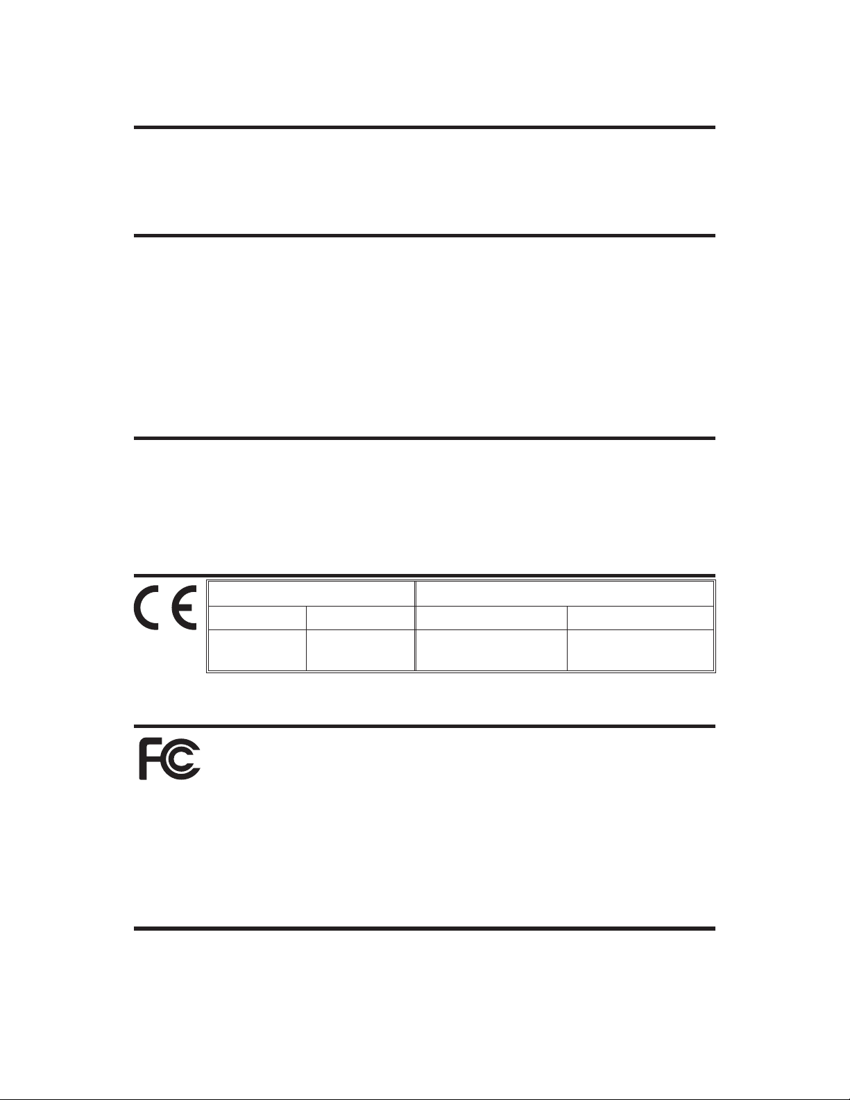
European Council Directive Compliance to Standards
89/336/EEC EMC Directive EN 55022-A, CISPR 22 RF Emissions control
92/31/EE EMC Directive EN 50082-1 IEC 801
Immunity to Electro
magnetic Disturbances
-
FCC - DECLARATION OF CONFORMITY:
Model: LP2824 conforms to the following specification:
FCC Part 15, Subpart B, Section 15.107(a) and Section 15.109(a) Class B digital de
vice
Supplemental Information:
This device complies with Part15 of the FCC Rules.Operation is subject tothe followingTwo Con
ditions: (1) This device may not cause harmful interference , and (2) this device must accept any
interference received, including interference that may cause undesired operation.
INDUSTRY CANADA NOTICE:
This device complies with Industry Canada ICS-003 class B requirements.
-
-
Cet equipement est conforme a l’ICS-003 classe B de la norm Industrielle Canadian
ii 980293-001 Rev. A
Page 3

WARRANTY INFORMATION
We Need To Hear From You!
To Establish Your Warranty Period And Provide Access To Technical Support,
Send Us Your Product Registration Card Today!
Zebra Technologies Corporation warrants the mechanism, control electronics and power supply,
under normal use and service, to be free from defects in material and workmanship for a period of
twelve (12) months from the date of purchase by the end user. Zebra Technologies Corporation
warrants the printhead, under normal use andservice, to befree from defects in materialand work
manship for aperiod of ninety (90) days or 30KM of printing (whichever occurs first) from thedate
of purchase by the end user. Proof of purchase or product registration is required. If proof of pur
chase or product registration cannot be established, shipment date to the original buyer (dealer or
distributor) will be used to establish the warranty period.
Failure to exercise caution to protect the equipment from electrostatic discharge damage, adverse
temperature and humidity conditionsor physicalabuse may void the warranty. Failure to use only
Eltron brand approved media may void the warranty. Zebra Technologies Corporation will, at its
option, repair or replace the equipment or any parts which are determined to be defective within
this warranty period, and which are returned to Zebra Technologies CorporationF.O.B. factory of
origin.
The warranty set forth above is exclusive and no other warranty, whether written or oral, is expressed or implied. Zebra TechnologiesCorporation specifically disclaims the implied warranties of
merchantability and fitness for a particular purpose.
-
-
RETURN MATERIALS AUTHORIZATION
Before returning any equipment to Zebra for in warranty or out of warranty repair, contact Repair
Administration for a Return Materials Authorization (RMA) number. Repack the equipment in the
original packing material and mark the RMA number clearly on the outside. Ship the equipment,
freight prepaid, to the address listed below:
Zebra Eltron Repair Administration, USA
1001 Flynn Road
Camarillo, CA. 93012
Phone: +1 (805) 579-1800
FAX: +1 (805) 579-1808
Label Printers: Card Printers:
Zebra Technologies, Europe Zebra Technologies, Europe
Zebra House Zone Indutrielle, Rue d'Amsterdam
The Valley Centre, Gordon Road 44370 Varades, France
High Wycombe Phone: +33 (0) 240 097 070
Buckinghamshire HP13 6EQ, UK FAX: +33 (0) 240 834 745
Phone: +44 (0) 1494 472872
FAX: +44 (0) 1494 450103
980293-001 Rev. A iii
Page 4
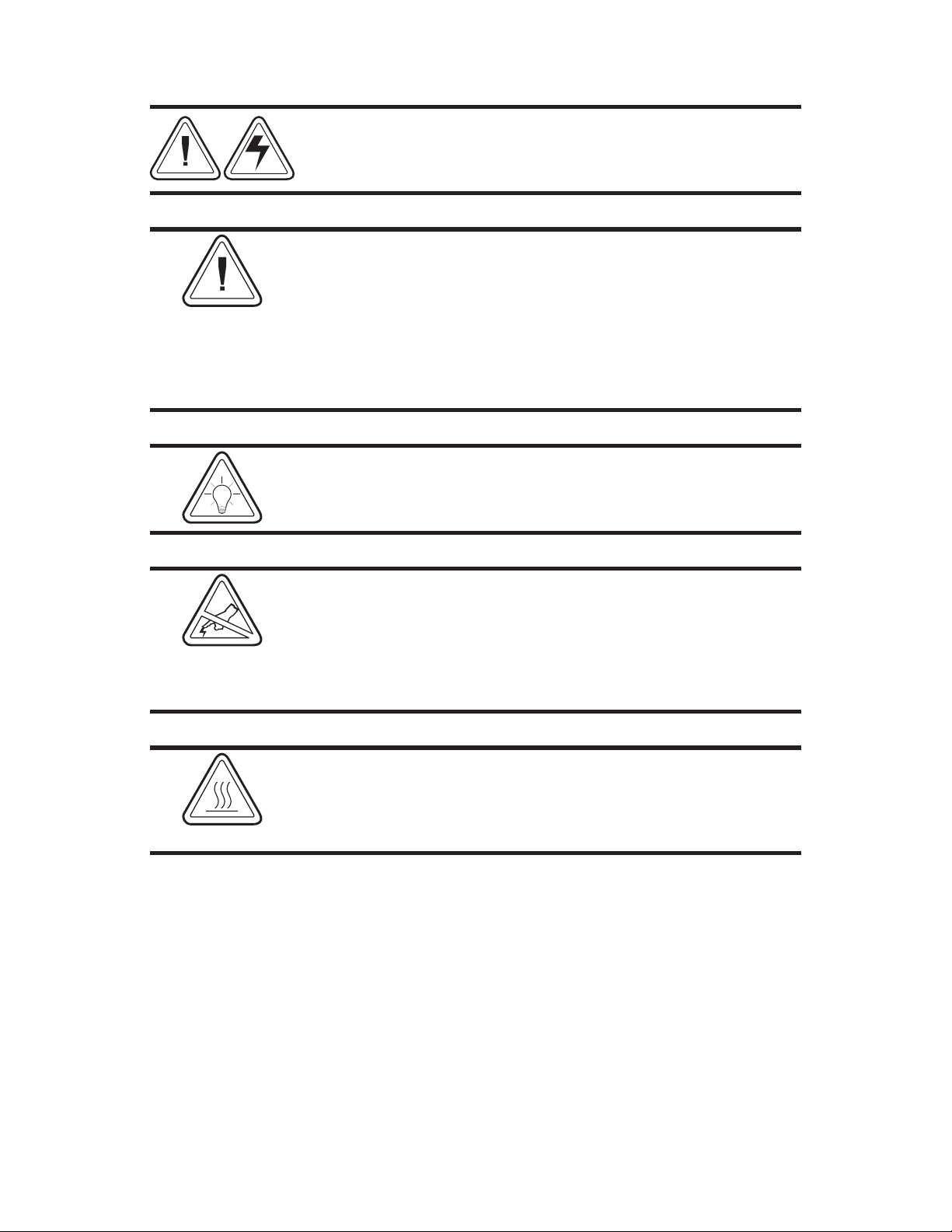
SHOCK HAZARD WARNING:
The printer and power supply should never be operated in a
location where either one can get wet. Personal injury could
result.
MEDIA WARNING:
Always use high quality Eltron approved labels, tags and
transfer ribbons. If adhesive backed labels are used that DO
NOT lay flat on the backing liner, the exposed edges may stick
to the label guides and rollers inside the printer, causing the
label to peel off from the liner and jam the printer. Eltron
approved supplies can be ordered from your ELTRON dealer.
For the name of a dealer in your area, call the nearest Eltron
office (located on the back of this manual).
RELOADING HINT:
If you should run out of labels while printing, DO NOT turn the
power switch OFF (0) while reloading or data loss may result.
The printer will automatically a new label roll is loaded.
STATIC DISCHARGE:
The discharge of electrostatic energy that accumulates on the
surface of the human body or other surfaces can damage or
destroy the print head or electronic components used in this
device.
DO NOT TOUCH the print head or the electronic components
under the top cover.
THERMAL PRINTING:
The print head becomes hot while printing. To protect from
damaging the print head and risk of personal injury, avoid
touching the print head. Use only the cleaning pen to perform
maintenance.
iv 980293-001 Rev. A
Page 5

TABLE OF CONTENTS
Installation and Operation .................1
Unpacking Your Printer ....................2
Getting To Know Your Printer .................3
Installation ...........................4
AutoSense Gap Sensor Adjustment ..............8
Label Dispenser Option ....................10
Using Fan-Fold Media .....................11
Appendix A - Troubleshooting ................13
Other Support Resources ...................15
Serial Interface Cable Wiring..................16
Cash Drawer Cable Wiring ..................17
Parallel Interface Cable Wiring .................18
Cleaning the Print Head ....................19
Appendix B - Accessories ..................20
980293-001 Rev. A v
Page 6

vi 980293-001 Rev. A
Page 7

1
Installation and Operation
This section provides information on the
installation and operation of the printer.
The printer is a low cost, desktop direct thermal
printer. The printer is specifically designed for
printing labels, tags or continuous receipts (with
or without bar codes) from any DOS™, Windows™or ASCII-based compatible host.
980293-001 Rev. A 1
Page 8
Installation and Operation
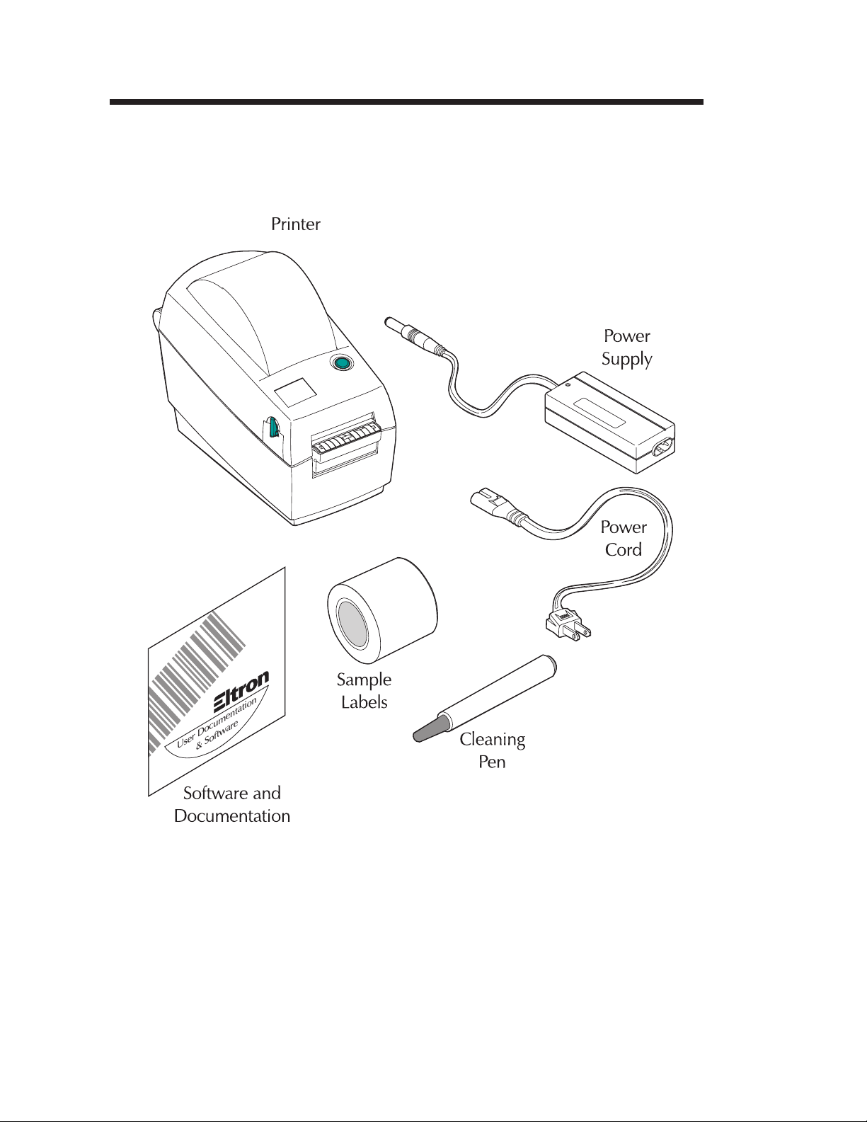
Unpacking Your Printer
User Documentation
&Software
2 980293-001 Rev. A
Page 9
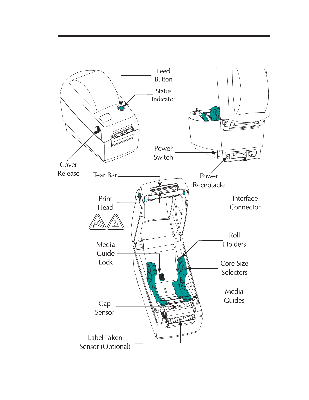
Getting To Know
Your Printer
Installation and Operation
980293-001 Rev. A 3
Page 10

Installation and Operation
Installation The following steps will guide you through the
installation of the printer and software.
Step ➊ Attach Power Supply To The Printer
Power OFF
Check Voltage
Plug in
Power
Module
Plug in
Power
Cord
Plug Power Cord
into a Suitable
AC Outlet
See the SHOCK HAZARD WARNING on page
iv.
4
980293-001 Rev. A
Page 11

Step ➋ Attach Interface Cable
The printer has either a parallel interface or a
serial interface (with optional RJ-11 connector).
Power OFF
Parallel Interface
Installation and Operation
RJ-11 Interface
(Optional)
Serial Interface
For additional information on serial cable wir
ing, refer to Appendix A.
980293-001 Rev. A 5
-
Page 12

Installation and Operation
Step ➌ Load Labels
Power ON
Open Cover
MOVIE
Adjust Holders
1.0 inch
2.5 cm
1.5 inch
3.8 cm
MOVIE
6 980293-001 Rev. A
Page 13

Load Labels - continued
Install Roll
Installation and Operation
Thread Through
Guides
Close Cover
Tap Feed Button
If the indicator remains dark, see Appendix A Troubleshooting.
980293-001 Rev. A 7
Page 14

Installation and Operation
Step AutoSense Gap Sensor Adjustment
Perform this procedure when loading a new
roll. If your printer has the label dispenser
option, turn OFF the label taken sensor.
Power OFF
MOVIE
Hold
Feed Button
Power ON
8
980293-001 Rev. A
Page 15

Installation and Operation
AutoSense Gap Sensor Adjustment - continued
When Indicator
Flashes, Release
Feed Button
Printer Advances
Media and Prints
Status Summary
Note: Printer is in
diagnostic dump mode
Tap Feed Button
To Begin Normal
Operation
Note: Printer prints
“out of DUMP”
4 MO3351F 16 V3.21
Serial port : 96,N,8,1
Image buffer size:245K
Fmem:000,0K,019.9K avl
Gmem:000K,0241K avl
E
mem:000K,0241K avl
I8,0,001 rY
S2 D8 R016,000 ZT UN
q800 Q1029,025
Option:
04 08 13
now in DUMP
If the indicator remains orange or red, see the
troubleshooting steps.
980293-001 Rev. A 9
Page 16

Installation and Operation
Label Dispenser Option
Open Door
Use a Stylus to
Switch On the
Label Taken Sensor
Remove Several
Labels
MOVIE
Push Liner
Through Slot
Close Door
10 980293-001 Rev. A
Page 17

Using Fan-Fold Media
Open Guides to
Width of Media
Lock Guides
in Place
Insert Media
Installation and Operation
Thread Media
Through Guides
980293-001 Rev. A 11
Page 18

Installation and Operation
Step ➎ Install Software
Start your computer and follow the installation
instructions on the compact disc (CD).
12
980293-001 Rev. A
Page 19

Appendix A - Troubleshooting
Problem Solution or Reason
STATUS Indicator
Does not light when power
switch is turned to ON (I)
position.
Lights GREEN, but printer
will not print.
Blinks GREEN-RED-RED.
Lights AMBER.
Blinks RED.
Lights RED.
Blinks GREEN-AMBER.
1. Check power connections from A.C.
outlet to power supply to printer.
1. Check interface cable connections from
computer to printer.
2. Make sure top cover is locked closed.
1. Operator has paused the printer during
a batch job. Tap the FEED button to
continue.
1. Printer has encountered a syntax or
command error.
1. The optional cover open sensor is active. Press top cover to close and lock.
1. Media is out. Reload a new source of
media so printer can continue printing.
2. Power-up failure.
1. AutoSense in process. Wait until printer
dispenses a status report.
Lights AMBER-RED.
1. Download in process.
Operation
1. Verify that the labels are the correct
Printer appears to be
working (media is being fed
out), but nothing is printed.
type (direct thermal).
2. Check that the roll is loaded with the di
rect thermal side facing up.
3. Clean the print head with cleaning pen.
-
4. Ensure top cover is locked closed.
Printing is faded or poor
quality.
980293-001 Rev. A 13
1. Clean the print head with cleaning pen.
2. Adjust print speed/darkness in software.
Page 20

Appendix A - Troubleshooting
Problem Solution or Reason
Prints only partial label or
skips a label.
1. Perform AutoSense gap sensor
adjustment on page 8.
2. Label caught on print head.
3. Print head is not properly latched.
4. Possible software problem. Check the
printer memory configuration. Refer to
the EPL2 Programming manual.
Printing stops and STATUS
indicator lights ORANGE or
RED.
1. Perform AutoSense gap sensor adjust
-
ment on page 8.
2. Possible problem with label stock. Use
only Eltron approved labels and tags.
3. Possible label jam.
4. Insufficient memory for label size. Check
the printer memory configuration.
5. Possible software problem. Refer to the
EPL2 Programming manual.
14 980293-001 Rev. A
Page 21

Appendix A - Troubleshooting
Other Support
Resources
The first troubleshooting reference source is the
table on the previous page. Next, contact the
dealer where you purchased your printer.
Zebra Technologies also provides a variety of
information and user support services:
Internet:
•
http://www.eltron.com
ftp: //ftp.eltron.com
e-mail:
Label Printers: techsup@eltron.com
Card Printers: cardsup@eltron.com
Europe: eurosup@eltron.com
Singapore: asiasup@eltron.com
Latin America: latinsup@eltron.com
• Customer Service: +1 (800) 344 4003
For the name of a dealer in your area.
• Technical Support FAX:
USA: +1 (805) 579 1808
Asia: +65 84 20 366
Europe: +44 (0) 1189 895 762
Latin America: +1 (847) 584 2725
For your assistance and support with Eltron
printers and software.
980293-001 Rev. A 15
Page 22

Appendix A - Troubleshooting
Serial Interface
Cable Wiring
The figure below displays the cable wiring
required to use the printer's RS-232 serial
interface.
DB-9
Pin #
N/C
RxD
TxD
DTR
GND
DSR
RTS
CTS
RI
Female DB-9 to Male DB-9
Cable P/N 300017-006 (6') or 300017-010 (10')
DB-25
Pin #
N/C
RxD
TxD
DTR
GND
DSR
RTS
CTS
RI
DB-9
Pin #
11
22
33
44
55
66
77
88
99
DB-9
Pin #
18
23
32
420
57
66
74
85
922
PrinterHost
+5 Volts*
TxD
RxD
N/C
GND
RDY
N/C
RDY
N/C
PrinterHost
+5 Volts*
TxD
RxD
N/C
GND
RDY
N/C
RDY
N/C
16
FemaleDB-25toMaleDB-9
Cable P/N 300018-006 (6')
*+5 volts at 150 mA for external device (e.g. KDU or scanner)
980293-001 Rev. A
Page 23

Appendix A - Troubleshooting
Cash Drawer
Cable Wiring
The figure below displays the pin assignments
for the printer's retail cash drawer interface. Re
fer to the cash draw manufacturer's documenta
tion for proper drawer wiring.
RJ-11
Pin No.
1
2
3
4
5
6
PRINTER
SGND
/SDRV1
/Sense
+24V*
/SDRV2
LGND
Male RJ-11
*+24 volts D.C. at no greater than 1.5 amps.
-
-
980293-001 Rev. A 17
Page 24

Appendix A - Troubleshooting
Parallel Interface
Cable Wiring
The figure below displays the cable wiring
required to use the printer's Centronics parallel
interface.
HOST
STROBE
DATA 0
DATA 1
DATA 2
DATA 3
DATA 4
DATA 5
DATA 6
DATA 7
ACK/
BUSY
PAPER ERR.
READY
INIT
ERROR/
N/A
N/A
N/A
SIG. GND
SIG. GND
SIG. GND
SIG. GND
SIG. GND
SIG. GND
SIG. GND
DB-25
Pin No.
1
2
3
4
5
6
7
8
9
10
11
12
13
14
15
16
17
18
19
20
21
22
23
24
25
Centronics
Pin No.
1
2
3
4
5
6
7
8
9
10
11
12
13
14
15
16
17
18
19
20
21
22
23
24
25
PRINTER
STROBE
DATA 0
DATA 1
DATA 2
DATA 3
DATA 4
DATA 5
DATA 6
DATA 7
ACK/
BUSY
PAPER ERR.
READY
INIT
ERROR/
N/A
N/A
+5V
SIG. GND
SIG. GND
SIG. GND
SIG. GND
SIG. GND
SIG. GND
FemaleDB-25toMaleCentronics
(Cable)
+5 volts at 300 mA for external device (e.g. KDU or scanner)
18 980293-001 Rev. A
Page 25

Appendix A - Troubleshooting
Cleaning the
Print Head
Rub Cleaning Pen
Across Dark Area
of Print Head
Wait One Minute
Before Closing
Printer
Do Not Clean Roller
When you load new media, you can also clean
the print head.
MOVIE
980293-001 Rev. A 19
Page 26

Appendix B - Accessories
Appendix B - Accessories
Accessories available for the printer are listed
below. Always refer to the ELTRON part num
ber when placing an order. For the name of an
Eltron brand dealer in your area, call: 1(805)
579-1800 or the nearest Zebra Technologies
office (located on the back of this manual).
Description Part Number
-
Parallel Interface Cable, 6’
Parallel Interface Cable, 10’
Serial Interface Cable, 6’ (DB-9 to DB-9)
Serial Interface Cable, 10’ (DB-9 to DB-9)
Serial Interface Cable, 6’ (DB-25 to DB-9)
Power Rewinder, 120V
Power Rewinder, 230V
Create-A-Label 3 Software for Windows
Keyboard Display Unit
User’s Manual (this manual)
Programmer’s Manual
Software and Documentation CD
300016-006
300016-010
300017-006
300017-010
300018-006
103284-001
103284-002
105524-001
120180-001
980293-001
980009-001
105551-001
20 980293-001 Rev. A
Page 27

Page 28

World Wide Offices:
Zebra Technologies Corporation
Eltron Products
1001 Flynn Road
Camarillo, CA 93012-8706 USA
Phone: +1 (805) 579 1800
FAX: +1 (805) 579 1808
e-mail: sales@eltron.com
Zebra Technologies, Europe
Zebra House
The Valley Centre, Gordon Road, High Wycombe
Buckinghamshire HP13 6EQ, UK
Phone: +44 (0) 1494 472872
FAX: +44 (0) 1494 450103
e-mail: eurosales@eltron.com
Zebra Technologies, France
50 rue Marcel Dassault
92100 Boulogne-Billancourt
France
Phone: +33 (0) 1 55 20 93 93
FAX: +33 (0) 1 55 20 93 99
e-mail: eurosales@eltron.com
Zebra Technologies, Latin America
6175 NW 153rd Street #121
Miami Lakes, FL 33014
Phone: +1 (305) 558 8470
FAX: +1 (305) 558 8485
e-mail: latinsales@eltron.com
Zebra Technologies, Asia/Pacific
1 Sims Lane #06-11
Singapore 387355
Phone: +65 84 20 322
FAX: +65 84 20 366
e-mail: asiasales@eltron.com
980293- 001A
 Loading...