

Page 1
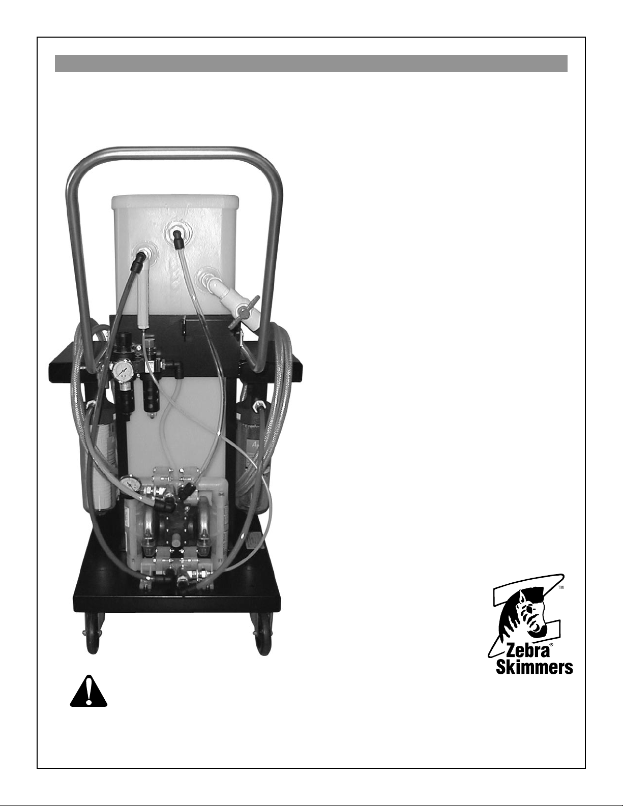
FM60-7309 Operator’s Manual
Zebra Skimmers Corp. Series FM 60 • Model Number 7309
Zebra
™
Snapdragon
™
Sierra
Water & Fines Removal Equipment
for Straight Oils
®
WARNING
This manual must be read and
understood before operating this piece
of machinery.
Warning! Failure to do so will void all warranties.
Printed in the USA • Revised April 2007
888-249-4855 • www.ZebraSkimmers.com • Zebra Skimmers Corporation Page 1
Copyright 2007 © ZSC
Zebra Skimmers Corp.
PO Box 833
Chagrin Falls, OH 44022
888-249-4855
www.ZebraSkimmers.com
Page 2

FM60-7309 Operator’s Manual
FM60-7309 Operator’s Manual
888-249-4855 • www.ZebraSkimmers.com • Zebra Skimmers Corporation Page 3
Table of Contents
Chapter One: Introduction to your Snapdragon Coalescer
1.0 Introduction to your Snapdragon Coalescer ………………………………………………… page 3
1.1 Limited Warranty Information ………………………………………………………………… page 3
1.2 Contacting Customer Support ………………………………………………………………… page 3
Chapter Two: Precautionary Safety Measures
2.0 Precautionary Safety Measures ……………………………………………………………… page 4
Chapter Three: Coalescing System Review
3.0 Component Review ……………………………………………………………………………page 5-6
3.1 Fluid Movement through the System ………………………………………………………… page 7
3.2 System Flow Schematic ……………………………………………………………………… page 7
Chapter Four: Coalescing System Operation & Maintenance Guidelines
4.0 Installation & Usage Guidelines ……………………………………………………………… page 8
4.1 Oil Accumulation & Waste Discharge ………………………………………………………… page 8
4.2 Finishing Up …………………………………………………………………………………… page 8
4.3 Emptying the Coalescing Tank ……………………………………………………………… page 9
4.4 Storing the System …………………………………………………………………………… page 9
4.5 Cleaning the System …………………………………………………………………………… page 9
Appendix: Third Party Equipment
Parker Pneumatic Filter Regulator ………………………………………………………… page 10-12
All Flo Diaphragm Pump ……………………………………………………………………… page 13-14
Calling Customer Support
If you have difculty assembling this product or have any questions regarding the
controls, operation, or maintenance of this unit, please call the Customer Support Line
at 888-249-4855.
For the latest details about the Zebra Snapdragon™ you can also visit our web site at
www.ZebraSkimmers.com.
Page 2 888-249-4855 • www.ZebraSkimmers.com • Zebra Skimmers Corporation
Page 3

Chapter 1
1.0 Introduction to Your Snapdragon
Coalescer
Thank you for purchasing the Zebra® Snapdragon™ Sierra™ Coalescer System to meet your oil maintenance
challenges.
This system is designed to be utilized on straight oil applications to lter out ne particulate and separate any
water-based liquid content. The oils will accumulate
inside the tank, and then be drawn through the ultra
lter to remove particulate. The ltered oil will then be
delivered against pressure to your holding vessel.
The water-based liquid content of your solution, if any,
will remain at the bottom the tank for manual discharge
to your waste container. Please make sure to discharge
the water portion on a timely basis so that oils are
always being fed to the ultra lter. If no oils are in the
holding tank of this unit, it will circulate the water portion
instead.
Please assemble, install, operate, and maintain this system in accordance with the guidelines provided in this
manual. This will help to insure that the unit performs
properly to your satisfaction.
FM60-7309 Operator’s Manual
in earnest and good faith to make this manual as comprehensive, complete and detailed as possible. However, all information contained herein is subject to change
without notice at the sole discretion of ZSC, or at the
discretion of third party vendors whose information has
been reprinted herein with their permission. ZSC is not
liable for any damages which may or may not be caused
by improper use of this equipment, as explicitly stated
within this operator’s manual. Furthermore, ZSC is not liable for the quality of information that may be contained
in, or unintentionally omitted from this manual. ZSC will
repair or replace such defective components at its sole
discretion. Customer must pay for shipping any parts or
the entire Zebra Snapdragon™ to or from ZSC repair
facilities, at the sole discretion of ZSC. Zebra Snapdragon™, ADAPT™, Sierra™, Zebra Sumpster™, and
Zebra Hammerhead™ are wholly owned trademarks of
the Zebra Skimmers Corporation.
1.2 Customer Support
If you would like any assistance in assembly or installation of this system, or have any questions on its use or
maintenance, please contact customer support at 888249-4855. We would be glad to help you and welcome
your feedback.
For the latest product details, please visit our web site
www.ZebraSkimmers.com.
1.1 Limited Warranty information
The Zebra® Snapdragon™ Coalescer is warranted for
one year from date of purchase against manufacturing
or material defects, except for disposable elements.
Individual warranties may apply to third party components, above and beyond this expressed warranty. This
warranty will be void, in full or in part, for any use not in
keeping with general safe operating procedures or any
of those principles outlined in this manual.
THE ABOVE WARRANTY IS EXCLUSIVE AND IN
LIEU OF ALL OTHER WARRANTIES, WHETHER
EXPRESSED OR IMPLIED, INCLUDING THE IMPLIED WARRANTIES OF MERCHANTABILITY, FITNESS FOR A PARTICULAR PURPOSE AND NONINFRINGEMENT. THIS WARRANTY GIVES YOU
SPECIFIC LEGAL RIGHTS. YOU MAY HAVE OTHER
RIGHTS, WHICH VARY FROM STATE TO STATE.
Zebra Skimmers Corp. (ZSC) has made every attempt
888-249-4855 • www.ZebraSkimmers.com • Zebra Skimmers Corporation Page 3
Page 4
FM60-7309 Operator’s Manual
FM60-7309 Operator’s Manual
888-249-4855 • www.ZebraSkimmers.com • Zebra Skimmers Corporation Page 5
Chapter 2
2.0 Precautionary Safety Measures
WARNING: Read, understand, and follow all instructions contained in this manual before starting. Keep
this manual in a safe, yet convenient, place for future reference.
WARNING: Failure to comply with all installation, operating, and maintenance guidelines will void all
warranties, may cause damage to the unit, or cause personal injury.
WARNING: It is the responsibility of the user to only allow individuals familiar with, and with full knowl-
edge of, this unit to install, operate, and maintain it. Zebra Skimmers Corp. will not be liable
for any damages due to lack of proper use of this equipment.
WARNING: Make sure you have the MSDS for your coolant on le, and measures related to its mixing,
measuring, maintenance, and disposal are read and understood. If you have any questions
regarding your specic coolant, contact your coolant supplier’s technical support service.
WARNING: Care must be taken at all times when handling coolant and waste oils. This includes utiliz-
ing safety glasses with side shield protection, gloves, longsleeved shirts and long-legged
pants. Sturdy shoes should also be worn, preferably with reinforced toes. Any liquids that
come into contact with the skin should be washed off with mild soap as soon as possible.
Liquid that comes into contact with the eyes should be washed out immediately with water
only.
WARNING: Tramp oils oating on coolant promote growth of anaerobic bacteria. These bacteria cre-
ate noxious gases, such as hydrogen sulde (H2S) and hydrochloric acid (HCl). Hydrogen
sulde causes unpleasant odors. Hydrochloric acid, however, can cause skin, eye, and
lung irritation. If these symptoms are present, consult a physician. Use the Zebra Muscle
Coalescer in a well- ventilated area to prevent these symptoms, should these gases be
present.
WARNING: Waste oil is hazardous and should be handled accordingly. Observe all proper national and
local disposal laws and regulations.
WARNING: Do not operate this equipment while under the inuence of drugs or alcohol.
WARNING: Do not put hands or feet in the barrel of this unit.
WARNING: While moving this equipment, slow down before turning corners to prevent tippage. To pre-
vent spillage, do not move the unit over hoses, mats, or other oor obstructions.
Page 4 888-249-4855 • www.ZebraSkimmers.com • Zebra Skimmers Corporation
Page 5
Chapter 3
3.0 Component Review
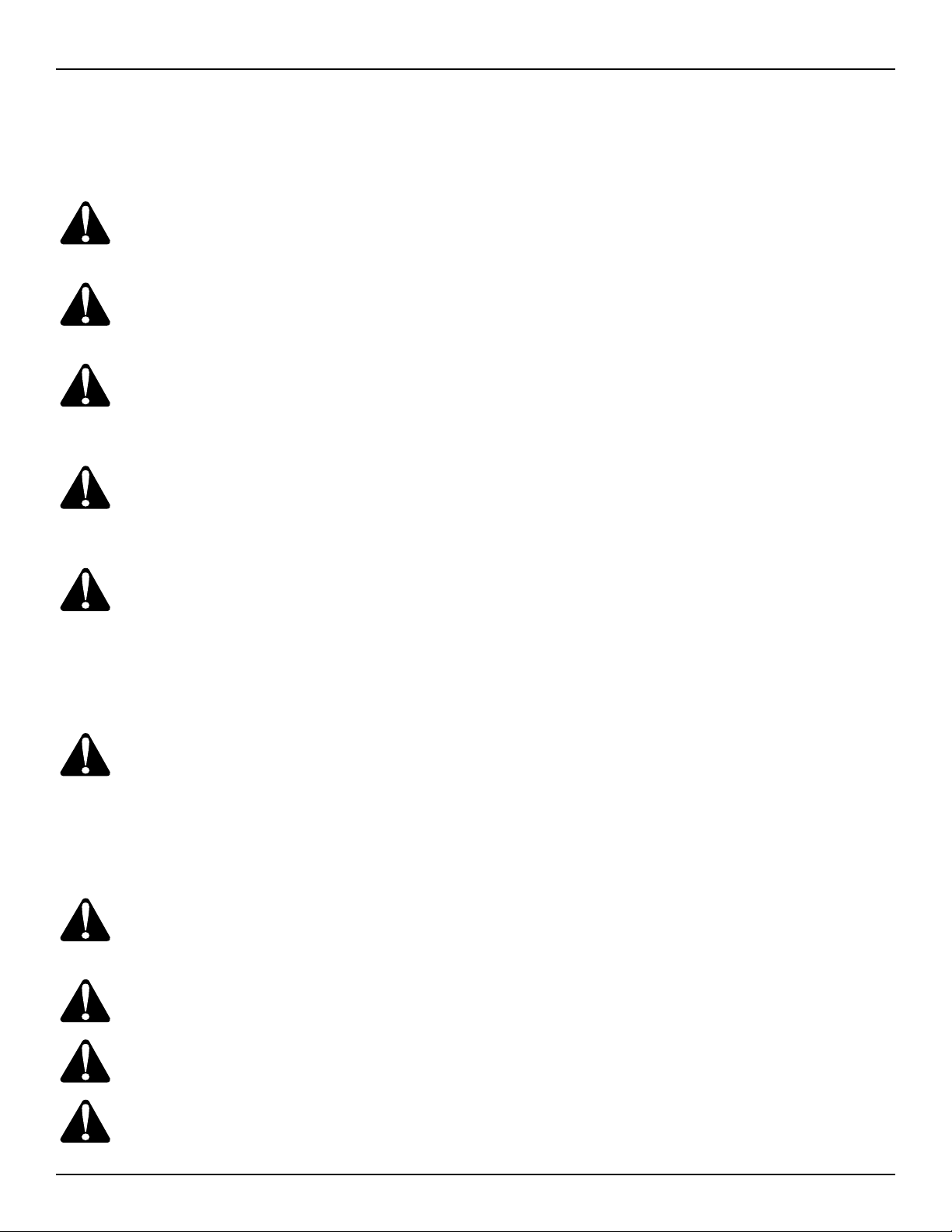
Sumpster™ Skimmer
This free-standing skimmer intake attachment can be mounted on the provided rod or on the
sump wall with a magnet, depending upon your tank depth.
Position the Sumpster so the
top of the box is 1/4” ABOVE the
maximum uid level in the tank.
It can handle a 3” uid level drop
once installed.
The chip screen will prevent large oating chips, such
as aluminum and plastic, from clogging the intake hose
or damaging the pump diaphragms and other internal
pump components. Periodically clean the debris to
maintain the 1 gpm ow rate of the system and to maximize the pump life.
Oil Wand™ Skimmer
This manual attachment is used
to clean machine
ways and other
hard to access
machine and
sump areas,
which also tend
to accumulate oil.
Just connect it to the intake hose when ready to use.
Cam Lock Quick-Connectors
We supply these connectors standard with
the Sierra. The female
is permanently xed to
the oil intake hose and
the male to the end of
the intake attachment.
Before making the connection, verify that the interiors of these connectors are
free of chips, debris, and oil residue to maintain a tight
seal.
FM60-7309 Operator’s Manual
Hoses
The 1/2”, clear braided hose is
industrial strength and will withstand use with water, coolants,
and oils. Over time, however,
they may become stiff, depending upon your overall tank conditions.
You may contact your distributor for replacement hose
or choose your own. If choosing your own, please select a grade that has a wall thickness comparable to our
standard to prevent wall collapse and thus poor system
performance. Periodically inspect them for any blockages caused by debris to maintain system performance
and maximize pump life.
Push-to-Connect Fittings
Zebra uses Department of Transportation-rated pushto-connect ttings for vacuum loss prevention
Pump Prelter
The pump prelter is made of
stainless steel with 500µ pores
to prevent debris from damaging
the pump.
It may be cleaned and reused as
long as the mesh integrity is maintained. After cleaning
and reinstallation, verify that the lter housing and o-ring
is free of debris to prevent vacuum loss.
Pressure Limiter
Zebra incorporates a pressure limiter to
prevent over-pressurization of the pump
diaphragms, which leads to immediate
pump failure.
If more than 85psi is needed to draw uid through the
system, thorough inspection of the intake attachment,
connectors, hoses, and ttings is needed. It is likely that
there is a vacuum leak caused by an improper seal of
one of the above components or there is a debris blockage in the system.
888-249-4855 • www.ZebraSkimmers.com • Zebra Skimmers Corporation Page 5
Page 6
FM60-7309 Operator’s Manual
FM60-7309 Operator’s Manual
888-249-4855 • www.ZebraSkimmers.com • Zebra Skimmers Corporation Page 7
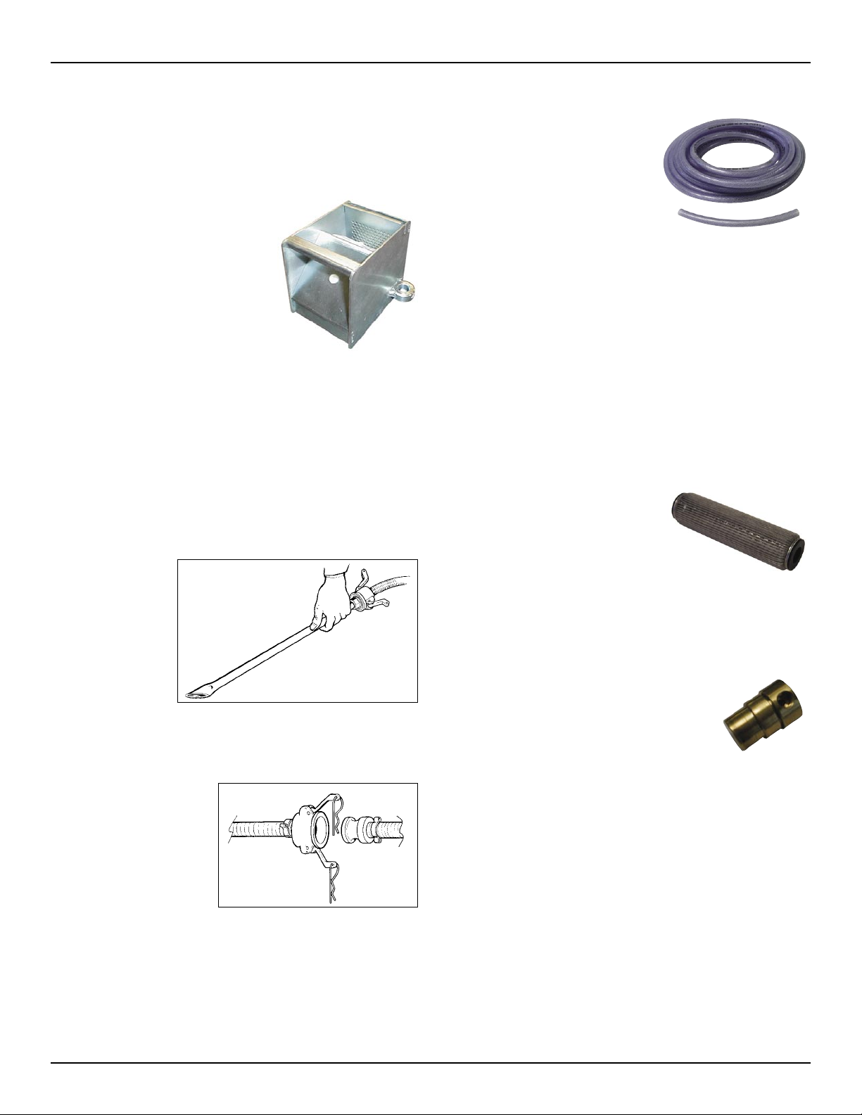
Pressure Regulator and Lubricator Package
Use the adjustment knob
of the pressure regulator to
adjust the air pressure going
through the pump. It must be
pulled up before adjusting.
Check the oil atomizer, located near the air line and
behind the regulator, to verify
Pressure
Regulator
that it is running at approximately one drop every 2-3
minutes. This atomizer feeds
lubrication to the air line and
should be relled with ISO
32 SAE10 Airline Lubricating
A Lubricator adjustment knob
B Air pressure adjustment knob
C Pressure gauge
D Filter drain
E Unscrew to ll lubricator
(mineral) Oil when necessary. Use of the wrong oil may
cause o-ring failure. If there is oil leaking from the mufer, adjust the oil atomizer valve.
Air-Diaphragm Pump
The 1/2” air diaphragm pump
is the heart of the system and
should be well maintained. Zebra has chosen this particular
brand pump for its durability and
ease of maintenance.
In normal operation, it will emit a
thumping sound. The faster the
sound, the faster uid is moving
through the system.
The pump can handle lifting uids 15 feet on the intake
side. However, it develops great pressures on the output side, and care must be taken to never try to restrict
the uid ow in any way.
For more information on the pump, please refer to the
Third Party Information in the Appendix of this manual.
Coalescing Tank
Bafed Anti-Turbulence System (BATS)
The BATS is made of PVC and acts to remove air
bubbles from the incoming uid. In so, turbulence is
lessened in the coalescing tank, aiding in the separation
of oil and water-based uids.
Pressurized Filtered Oil Return System
The oil return piping system will remove oil from the
coalescing tank, circulating it through the pump to the
ultralter. After ultraltration, it is then pumped under
pressure to your holding vessel.
Ultralter
The Sierra is equipped with a 5µ ultralter,
standard. This lter cartridge is made of
cellulose and should not be reused, but replaced, when necessary. Reuse of this lter
may cause damage to the pump and void all
warranties.
Periodically inspect the cartridge to determine whether it needs replacement. Another
good indication for replacement is if the
system requires more than 40psi to maintain the proper
ow rate. Also verify that the o-ring is free of debris before reinstallation.
Overll Prevention Line
This line, which is the 1/4” clear hose, recirculates up to
10% of the uid back through the right side of the pump
to prevent the coalescing tank from overowing.
Ball Valve for Waste Fluid Discharge
The waste uid, whether it’s water or coolant, will settle
on the bottom of the coalescing tank. It will be necessary
to manually discharge this uid to a waste container before its level reaches that of the oil return piping. NOTE:
Waste waters will recirculate through the ultralter and
into your holding vessel if not regularly discharged.
The coalescing tank is made of polyethylene to withstand oils and coolant. It is not made to withstand
punctures or shock, so care must be taken to prevent
damage.
It can hold approximately 19 gallons of liquid. You will
need to prell the tank with oil only in the event that your
application requires no oil to be “removed” from the tank
in service.
Page 6 888-249-4855 • www.ZebraSkimmers.com • Zebra Skimmers Corporation
Page 7

3.1 Fluid Movement through the System
• Intake attachment
• Intake hose
• Prelter, 500µ stainless steel
• Pump, right side
• BATS
• Coalescing tank
• Overll prevention line (10% of uid only)
• Pump, left side
• Ultralter, 5µ cellulose
• Pressurized oil return hose
• Wasterwaters will accumulate in the coalescing tank until manually discharged
3.2 System Flow Schematic
FM60-7309 Operator’s Manual
Please review the ow schematic of the
Snapdragon Sierra before attempting
to install and utilize the system. Understanding the system will aid in accident prevention, provide for ease
of use, and help keep you satised
with its performance.
888-249-4855 • www.ZebraSkimmers.com • Zebra Skimmers Corporation Page 7
Page 8

FM60-7309 Operator’s Manual
FM60-7309 Operator’s Manual
888-249-4855 • www.ZebraSkimmers.com • Zebra Skimmers Corporation Page 9
Chapter 4 System Operation & Maintenance
4.0 Installation & Usage Guidelines
1. Inspect the unit to make sure it is in good operating condition.
2. Fill the coalescing tank with 3 gallons of water to
ll the waste discharge pipe column. NOTE: If
the coalescer tank is not pre-lled, oils will enter
this column and your rst waste discharge may
contain oil until this column lls with water-based
uid.
3. Secure the ltered oil return hose to your preferred holding vessel using the magnet, provided.
4. Install your preferred uid intake attachment, according to the guidelines in Section 3.0, quickconnecting it to the uid intake hose.
5. Connect your air hose to the air connection tting.
6. Lift the air regulator knob and adjust until the
pressure is approximately 10-20 psi. NOTE:
You will need to adjust this pressure higher as
the lters ll with debris, if there is a blockage
in a line or tting, or there is a loss of vacuum
pressure due to an improper seal. In each of the
previous cases, it is recommended to correct
the problem and not use excessive pressure
to operate the system. This will ensure a proper
ow rate for maximum oil/water separation.
4.1 Oil Accumulation for
Ultraltration & Waste Discharge
Once the uid is drawn into the coalescing tank, it will
begin to separate into two main layers. The oil component will oat towards the top of the tank and water-based uids will accumulate near the bottom of the
coalescing tank. The degree of this separation will be
strictly determined by these factors:
• The strength of the water-based uids anti-emulsi-
cation components (as in metalworking uid, aka
coolants)
• The age and quality of the water-based uid to be
manually discharged
• The age and quality of the oil to be ultraltered
• Chemical instabilities caused by other additives en-
tering uid pool
• The ow rate of the coalescing system
Maintain a regulated ow rate so it provides for a proper
hold time for all uids to separate, usually 1-2 gallons
per minute.
If there is not a complete separation of the oil and water
portions, then a slower ow rate may be necessary, as
your uids have lost the ability to gravity separate within
10-20 minutes. You may notice a third layer which does
not completely separate at all. These are called inverse
layers, and are generally caused by high-pressure systems which further emulsify oils into one another. Consider this layer as waste and discharge it regularly.
The Snapdragon Sierra is not guaranteed to separate
a straight oil from another straight oil and/or tramp oils.
Before reusing any straight oil, verify its integrity.
Manually discharge the wastewater portion to a waste
container, via the ball valve, so as not to recirculate it
through the ultralter and into your preferred holding
vessel. NOTE: We recommend maintaining a waste
water level of about a third of the tank heighth to maintain the separated uid layers. ALWAYS discharge the
waste uid while the pump is running to prevent vacuum
loss in the waste discharge pipe.
Page 8 888-249-4855 • www.ZebraSkimmers.com • Zebra Skimmers Corporation
Page 9

FM60-7309 Operator’s Manual
4.2 Finishing Up
1. Once the oils have been removed from the tank
being skimmed, disconnect the intake hose from
the intake attachment via the quick connection.
2. Before shutting off the pump, lift the intake hose
out of the tank for about 10 seconds. This will
ensure that no liquid is still in the intake line.
3. Shut the pump off by adjusting the regulator.
NOTE: See Section 4.3 for details on emptying the tank, if necessary, before proceeding
further.
4. Disconnect your air line from the air intake tting.
5. Remove the return line from the tank being
skimmed by lifting it near its connection to the
coalescing tank to free it of liquid.
4.3 Emptying the Coalescing Tank
1. Open waste water ball valve to manually drain
any wastewater to your waste container, then
close (refer to ow schematic in Section 3.2).
4.4 Storing the System
It is recommended to empty the coalescing tank before
storing the system for more than 1 or 2 days. Holding liquid in the tank can contribute to bacterial contamination
of the coalescer, and thus your equipment. We recommend utilizing an Oxygenator™ when storing uids in
the coalescing tank to minimize bacterial growth.
4.5 Cleaning the System
1. Empty and clear the coalescing tank and both
hoses of all uids (refer to Section 4.3)
2. Discard the cellulose ultralter.
3. Mix a 10% solution of a mild degreasing agent,
such as Red Thunder™, provided, to clean the
coalescing tank and stainless steel prelter. A
pressure washer works well, or just clean by
hand with the brush, provided.
4. Rinse thoroughly with straight water.
5. Dispose of wash and rinse baths in accordance
to federal, state, and local environmental laws
and regulations.
2. Tilt, in an upward position, the prelter and ultralter housings.
3. Close ball valve for the oil ultraltration line (refer
to ow schematic in Section 3.2).
4. Open ball valve for oils to be emptied from tank
(refer to ow schematic in Section 3.2).
5. Place the oil return line into your preferred oil
holding vessel. Make sure that it can hold the remaining amount of oil left in the coalescing tank.
CAUTION: Fluid is returned under pressure.
6. Adjust the air regulator of the pump to 10psi.
6. Replace lters, making sure o-rings are free of
debris and seated correctly.
7. Double-check all hoses, ttings, and attachments for cracks and obstructions.
888-249-4855 • www.ZebraSkimmers.com • Zebra Skimmers Corporation Page 9
Page 10

FM60-7309 Operator’s Manual
FM60-7309 Operator’s Manual
888-249-4855 • www.ZebraSkimmers.com • Zebra Skimmers Corporation Page 11
Appendix: Third Party Equipment
Contents
Parker Pneumatic Filter/Regulator …………………… 10-11
Parker Pneumatic 14E Mini Filter/Regulator ………… 11-12
ALL-FLOW PUMP ……………………………………… 13-14
Parker Pneumatic Filter/Regulator
Pneumatic Division North America
Richland, Michigan 49083
WARNING
To avoid unpredictable system behavior that can cause personal injury and property damage:
• Disconnect air supply and depressurize all air lines connected to this product before
installation, servicing, or conversion.
• Operate within the manufacturer ’s specied pressure, temperature, and other conditions
listed on these instructions.
• Medium must be moisture-free if ambient temperature is below freeing.
• Service according to procedures listed in these instructions.
• Installation, service, and conversion of these products must be performed by knowledgeable
personnel who understand how pneumatic products are to be applied.
• After installation, servicing, or conversion, air supply should be connected and the product
tested for proper function and leakage. If audible leakage is present, or the product does
not operate properly, do not put into use.
• Warnings and specications on the product should not be covered by paint, etc. If masking
is not possible, contact your local representative for replacement labels.
Introduction
Follow these instructions when installing, operating, or servicing the product.
Application Limits
These products are intended for use in general purpose compressed air systems
only
Operating Inlet Pressure:
kPa PSIG bar
with Polycarbonate Bowl 1000 150 10.3
with Metal Bowl 1700 250 17.0
Note: The maximum recommended pressure drop for a particulate lter is 70 kPa
(10 psig, 0.7 bar).
Ambient Temperature Range:
with Polycarbonate Bowl O°C to 52°C (32°F to 125°F)
with Metal Bowl O°C to 52°C (32°F to 175°F)
Symbols
Filter/Regulator Filter/Regulator 12E
05E, 06E & 07E (Coalescing Element)
Installation
1. The lter/regulator should be installed with reasonable accessibility for service
whenever possible - repair service kits are available. Keep pipe or tubing lengths to
a minimum with inside clean and free of dirt and chips. Pipe joint compound should
be used sparingly and applied only to the male pipe - never into the female port. Do
not use Teon† tape to seal pipe joints - pieces have a tendency to break off and
lodge inside the unit, possibly causing malfunction. Also, new pipe or hose should be
installed between the lter/regulator and equipment being protected.
2. The upstream pipe work must be clear of accumulated dirt and liquids.
3. Select a lter/regulator location as close as possible to the equipment being
protected.
4. Install lter/regulator so that air ows in the direction of arrow on body.
5. Install lter/regulator vertically with the bowl drain mechanism at the bottom. Free
moisture will thus drain into the sump (“quiet zone”) at the bottom of the bowl.
6. Gauge ports are located on both sides of the lter/regulator body for your
convenience. It is necessary to install a gauge or socket pipe plugs into each port
during installation.
Operation
1. Both free moisture and solids are removed automatically by the lter. Units with
coalescing elements (e.g. 12E series) also remove oil. For coalescing units, a 5
micrometer pre-lter is recommended to protect and prolong the life of the coalescent
lter element.
2. Manual drain lters must be drained regularly before the separated moisture and
oil reaches the bottom of the bafe or end cap.
3. The lter element should be removed and replaced when pressure differential
across the lter is 69 kPa (10 psig).
4. Before turning on the air supply, turn the knob counterclockwise until compression
is released from the pressure control spring. Then turn knob clockwise and adjust
regulator to desired downstream pressure. This permits pressure to build up slowly
in the downstream line.
5. To decrease regulated pressure settings, always reset from a pressure lower than
the nal setting required. Example, lowering the secondary pressure from 550 to 410
kPa (80 to 60 psig) is best accomplished by dropping the secondary pressure to 350
kPa (50 psig), then adjusting upward to 410 kPa (60 psig).
6. When desired secondary pressure settings have been reached, push the knob
down to lock this pressure setting.
Service
Caution: Disconnect or shut off air supply and exhaust the primary and secondary
pressures before servicing unit. Turning the adjusting knob counterclockwise does
not vent downstream pressure on non-relieving regulators. Downstream pressure
must be vented before servicing regulator.
Note: Grease packets are supplied with kits for lubrication of seals. Use only mineral
based grease or oils. Do not use synthetic oils such as esters. Do not use silicones.
Note: After servicing unit, turn on air supply and adjust regulator to the desired
downstream pressure. Check unit for leaks. If leakage occurs, do not operate conduct repairs and retest.
Servicing Filter Element
A. 05E, 06E, & 07E Units (Refer to Figure 1.)
1. Unscrew the bottom threaded collar and remove bowl.
2. Unscrew the bafe and then remove element.
3. Clean all internal parts and bowl before reassembling. See polycarbonate bowl
cleaning section. IMPORTANT: The 05E & 06E Filter/Regulator will not operate
properly if the deector (or rubber spacer if using an 06E adsorber) is not installed
properly. The deector (or rubber spacer) must be installed between the lter stem
and the lter body
4. Install new element.
5. Attach bafe and nger tighten rmly.
6. Replace bowl seal. Lightly lubricate new seal to assist with retaining it in
position.
7. Install bowl into body and tighten collar; hand tight, plus 1/4 turn.
WARNING FAILURE OR IMPROPER SELECTION OR IMPROPER USE OF THE
PRODUCTS AND/OR SYSTEMS DESCRIBED HEREIN OR RELATED ITEMS CAN
CAUSE DEATH, PERSONAL INJURY AND PROPERTY DAMAGE.
This document and other information from Parker Hannin Corporation, its
subsidiaries and authorized distributors provide product and/or system options for
further investigation by users having technical expertise. It is important that you
analyze all aspects of your application, including consequences of any failure and
review the information concerning the product or system in the current product
catalog. Due to the variety of operating conditions and applications for these products
or systems, the user, through its own analysis and testing, is solely responsible
for making the nal selection of the products and systems and assuring that all
performance, safety and warning requirements of the application are met.
The products described herein, including without limitation, product features,
specications, designs, availability and pricing, are subject to change by Parker
Hannin Corporation and its subsidiaries at any time without notice.
05E, 06E, 07E, & 12E Filter/ Regulator Series
B. 12E Units (Refer to Figure 2.)
1. Hold bowl collar stationary while unscrewing and removing bowl.
2. Unscrew end cap and then remove element. (Do not remove threaded rod.)
3. Clean all internal parts and bowl before reassembling.
4. Install new element.
5. Attach end cap and nger tighten rmly,
6. Replace bowl seal. Lightly lubricate new seal to assist with retaining it in
position.
7. Thread bowl into collar; hand tighten until bowl stops against collar.
Servicing Regulator
A. 05E, 06E, & 07E Units - (Refer to Figure 1.)
1. Disengage the adjusting knob by pulling upward. Turn adjusting knob
counterclockwise until the compression is released from the pressure control spring.
2. Remove the bonnet and bowl assemblies by unscrewing the two threaded
collars.
3. Remove diaphragm assembly from bonnet assembly.
4. Remove lter stem, lter element, poppet assembly, poppet return spring, (seat)
insert and its o-rings.
5. Clean and carefully inspect parts for wear or damage. If replacement is necessary,
use parts from service kits. Clean bowl. See polycarbonate bowl cleaning section.
6. Lubricate o-ring and vee packing seals with grease found in service kits.
7. Install poppet return spring, poppet assembly, (seat) insert and its o-rings, and
lter stem. IMPORTANT: The 05E & 06E Filter/Regulator will not operate properly if
the defector (or rubber spacer if using an 06E adsorber) is not installed properly. The
deector (or rubber spacer) must be installed between the lter stem and lter body.
8. Install lter element and rmly tighten bafe onto the lter stem.
9. Install diaphragm assembly into bonnet assembly. Assemble bonnet assembly to
body and tighten threaded collar from 5.4 to 5.9 N•m (48 to 52 in-lbs).
10. Install bowl into body and tighten collar; hand tight, plus 1/4 turn,
B. 12E Units - (Refer to Figure 2.)
1 . Disengage the adjusting knob by pulling upward. Turn adjusting knob
counterclockwise until the compression is released from the pressure control spring.
2. Remove the bonnet assembly by unscrewing its threaded collar.
Page 10 888-249-4855 • www.ZebraSkimmers.com • Zebra Skimmers Corporation
Page 11

FM60-7309 Operator’s Manual
3. Remove the bottom collar
and bowl as an integral unit.
Note: The reverse ow adapter
and element assembly should
remain in proper alignment
with the collar; they are held in
place by the o-ring between the
adapter and the collar.
4. Remove diaphragm
assembly from bonnet
assembly.
5. Remove poppet assembly,
poppet return spring, (seat)
insert and its o-rings.
6. Clean and carefully inspect
parts for wear or damage. If
replacement is necessary, use
parts from service kits.
7. Lubricate o-ring and vee
packing seals with grease found
in service kits.
8. Install poppet return spring,
poppet assembly, (seat) insert
and its o-rings.
9. Install diaphragm assembly
into bonnet assembly. Assemble
bonnet assembly to body and tighten threaded collar from 5.4 to 5.9 N•m (48 to 52
in-lbs).
10. Install bottom collar and bowl subassembly into body. Tighten collar hand tight,
plus 1/4 turn.
Safety: Polycarbonate Bowls
Bowl guards are recommended for added protection of polycarbonate bowls where
chemical attack may occur.
WARNING To avoid polycarbonate bowl rupture that can cause personal injury or property damage,
do not exceed bowl pressure of temperature ratings. Polycarbonate bowls have a 150 psig (1030 kPa)
pressure rating and a maximum temperature rating of 52°C (125°F).
MAINTENANCE 05E 06E 07E 12E
SERVICE KITS 1/8”,1/4” & 3/8” 1/4”, 3/8” & 1/2” 3/8”,1/2” & 3/4” 3/8”,1/2” & 3/4”
Element Kits
5 Micron PS902P PS702P PS802P N/A
40 Micron PS901P PS701P PS801P N/A
Grade 6 N/A N/A N/A PS884P
Grade 10 N/A N/A N/A PS885P
Relieving Regulator
Repair Kit PS908P PS71OP PS81OP PS886P
Non-Relieving
Regulator Repair Kit PS909P PS711P PS811P PS887P
EXTRA COPIES OF THESE INSTRUCTIONS ARE AVAILABLE FOR INCLUSION IN EQUIPMENT/
MAINTENANCE MANUALS THAT UTILIZE THESE PRODUCTS. CONTACT YOUR LOCAL
REPRESENTATIVE.
Parker Pneumatic 14E Mini Filter/Regulator
Pneumatic Division North America
Richland, Michigan 49083
WARNING
To avoid unpredictable system behavior that can cause personal injury and
property damage:
• Disconnect electrical supply (when necessary) before installation, servicing, or
conversion.
• Disconnect air supply and depressurize a[ air lines connected to this product
before installation, servicing, or conversion.
• Operate within the manufacturer’s specied pressure, temperature, and other
conditions listed In these instructions.
• Medium must be moisture-free if ambient temperature is below freezing.
• Service according to procedures listed in these instructions.
• Installation, service, and conversion of these products must be performed by
knowledgeable personnel who understand how pneumatic products are to be
applied.
• After installation, servicing, or conversion, air and electrical supplies (when
necessary) should be connected and the product tested for proper function and
leakage. If audible leakage is present, or the product does not operate properly,
do not put into use.
• Warnings and specications on the product should not be covered by paint, etc.
If masking is not possible, contact your local representative for replacement
labels.
Introduction
Follow these instructions when installing, operating, or servicing the product.
Application Limits
These products are intended for use in general purpose compressed air systems
only Compliance with the rated pressure and temperature is necessary
Maximum Operating (Inlet) Pressure: kPa psig bar
P3A-RN, 8AR (Plastic Body) 827 120 8.3
14E (with Plastic Bowl) 1030 150 10.3
14E (with Metal Bowl) 1720 250 17.2
14R (Metal Body) 2000 300 20.0
15R (Metal Body) 1720 250 17.2
Ambient Temperature Range: O°C to 52°C (32°F to 125°F)
Symbols
14E P-RN, 8AR 14R & 15R
Manual Drain Filter Relieving Regulator
Relieving Regulator
Installation
1. This unit should be installed with reasonable accessibility for service whenever
possible - repair service kits are available. Keep pipe and tubing lengths to a
minimum with inside clean and free of dirt and chips. Pipe joint compounds should
be used sparingly and applied only to the male pipe - never into the female port. Do
not use PTFE tape to seal pipe joints - pieces have a tendency to break off and lodge
inside the unit, possibly causing malfunction.
2. Install unit so that air ow is in the direction of arrow. Installation must be
upstream of and close to devices it is to service (valve, cylinder, tool etc.). Mounting
of regulators may be in any position; mounting of lter/regulators must be vertical as
shown in gure.
3. Gauge ports are located on both sides of the regulator body for your convenience.
It is necessary to install a gauge or pipe plug into each port during installation.
4. To protect regulator units against rust, pipe scale, and other foreign matter, install
a lter on the upstream (high pressure) side as close to the regulator as possible.
Caution: For proper assembly of P3A-RN and 8AR ttings, they must be installed
hand-tight and then tightened by wrench 1/2 turn. To prevent leakage past
threads, apply thread sealant to tting. Prestolok ttings are recommended. Use
of hard pipe is not recommended.
EXCESSIVE TURNING OF FITTINGS BY WRENCH MAY RESULT IN
PERMANENT DAMAGE AND RENDER THE REGULATOR INOPERABLE.
Operation of Regulator
1. Before turning on air supply, turn adjusting handle counterclockwise until
compression is released from control spring. Then turn on air supply and adjust
regulator to desired secondary pressure by turning adjusting handle clockwise. This
permits pressure to build up slowly, preventing any unexpected operation of the valve,
cylinders, tools, etc., attached to the line. Adjustment to desired secondary pressure
can be made only with primary pressure applied to the regulator,
2. To decrease regulator pressure setting, always reset from a pressure lower than
the nal setting desired. For example, lowering the secondary pressure from 550 to
410 kPa (80 to 60 psig) is best accomplished by dropping the secondary pressure to
350 kPa (50 psig), then adjusting upward to 410 kPa (60 psig).
Operation of Filter/Regulator
1. Both free moisture and solids are removed automatically by the Filter/Regulator.
2. Manual drain lters must be drained regularly before the separated moisture and
oil reaches the bottom of the element holder. Automatic drain models (pulse drain)
will collect and dump liquids automatically. They are actuated when a pressure drop
occurs within the lter.
3. The lter element should be removed and replaced when the pressure differential
across the lter is excessive.
Service
Caution: SHUT OFF AIR SUPPLY and exhaust the primary and secondary
pressure before disassembling unit. (Units may be serviced without removing
them from the air line.)
Servicing Regulator:
Note: See Figure 1, 2, 3 & 4 to aid with this procedure.
1. Unlock the adjusting knob by pulling upward (with the unit in an upright position.)
Then turn adjusting knob counterclockwise until compression of the control spring
has been removed.
2. Remove the bonnet from body. Then remove o-ring (7), piston, lip seal (9), and
control spring to service the bonnet subassembly. Unscrew seat (8) to service the
poppet (17), return spring (5), and/or poppet seal (6), o-rings (25 & 27), and washer
(26).
Note: On lter/regulator units, the poppet assembly & poppet return spring may be
accessed by removing lter element.
3. Clean old grease from unit and inspect seals for sign of wear (nicks, cuts, and
scratches). Repair kits are available which contain the parts which are typically
replaced.
4. Apply a light lm of grease to all seals and sliding surfaces using the grease
packet supplied with repair kit.
Note: Refer to Figures to determine the correct position and orientation of the
888-249-4855 • www.ZebraSkimmers.com • Zebra Skimmers Corporation Page 11
Page 12

FM60-7309 Operator’s Manual
FM60-7309 Operator’s Manual
888-249-4855 • www.ZebraSkimmers.com • Zebra Skimmers Corporation Page 13
various parts during assembly.
5. On relieving 15R units, gently and rmly press vent seal into piston using a blunt
instrument.
6. Install lip seal onto piston with the lips of the seal facing away from the support
ange. Then insert control spring and piston assembly into bonnet.
7. On 15R units, place balancing o-ring (27) and washer (26) into body’s bore. Then
insert poppet return spring and poppet assembly, followed by seat o-ring (25) and
seat. On 14E, P3A-RN, 8AR & 14R units, place poppet return spring and poppet
assembly into bore, followed by poppet seal and seat.
8. On 15R units, tighten seat from 0.6 to 0.8 Nm (5 to 7 in-lbs). On 14E, P3A-RN,
8AR & 14R units, tighten seat to body from 0.9 to 1.1 Nm (8 to 10 in-lbs) of torque.
Tighten bonnet onto body from 5.6 to 7.3 Nm (50 to 65 in-lbs) of torque.
9. Make sure that the control spring is still uncompressed before turning on the
air supply Turn on air supply, then slowly adjust the knob clockwise to increase
downstream pressure until the desired pressure has been reached.
10. To decrease regulator pressure setting, always reset from a pressure lower than
the nal setting desired. For example, lowering the secondary pressure from 550 to
410 kPa (80 to 60 psig) is best accomplished by dropping the secondary pressure to
350 kPa (50 psig), then adjusting upward to 410 kPa (60 psig).
11. When the desired secondary pressure setting has been reached, push the
adjusting knob down to lock it.
12. Check for leaks. If leaks occur, shut off the air supply, exhaust system air
pressure, and make necessary adjustments to eliminate leakage.
Servicing Filter Element:
Note: See Figure 1 to aid with this procedure.
1 . Unscrew threaded bowl and element holder. Then remove lter element,
deector, and gaskets.
2. Clean all internal parts, bowl, and body before re-assembling unit. See
Polycarbonate bowl cleaning section.
3. Install deector, lter element, and gaskets.
4. Attach element holder. Torque 0.9 to 1.4 Nm (8 to 12 in-lbs).
5. To assist with retaining bowl’s o-ring while installing bowl, lubricate the o-ring (with
a mineral based oil or grease). Then place it on the bowl.
6. Screw bowl into body until it is stopped by body; then back off bowl 1/8 turn.
7. Apply pressure to the system and check for leaks. If leaks occur, shut off the
air supply, de-pressurize the system and make necessary adjustments to eliminate
leakage. If you have questions concerning how to service this unit, contact your local
authorized dealer or your customer service representative.
Parts Identication List
Item# Description
1 Bowl (14E)
2 Filter Element (14E)
3 Deector (14E)
4 O-ring (14E) - bowl to body
5 Poppet Return Spring
6 Poppet Seal
7 O-ring - body to bonnet
8 Seat
9 Lip Seal - piston to bonnet
10 O-ring (14E, P3A-RN, 8AR & 14R relieving
units) - piston to poppet
11 Piston (relieving shown)
12 Control Spring
13 Knob
14 Hex Nut
15 Adjusting Screw
16 Bonnet Assembly
17 Poppet (14E, P3A-RN, 8AR & 14R) & Poppet
Assembly (15R)
18 Body
19 Gasket (14E) - deector to body
20 Gasket (14E) - element holder to lter
element
21 Element Holder (14E)
22 O-ring (14E) - body to drain
23 Twist Drain (14E)
24 Vent Seal (15R, relieving units) - poppet
assembly to piston
25 O-ring (15R) - seat to body
26 Washer
(balanced
units)
27 O-ring
(balanced
units)
- poppet
assembly to
body
Service Kits Available
The following service kits contain the appropriate seals and parts necessary for
ordinary eld service.
Description 14E P3A-RN, 8AR & 14R 15R
Poppet Kit - Balanced N/A N/A PS455BP
Piston Kit - Non-Relieving N/A N/A PS422P
Piston Kit - Relieving N/A N/A PS423P
Piston & Poppet Kit - Unbal. Rel. PS426P PS426P N/A
Piston & Poppet Kit - Bal. Rel. PS427P PS427P N/A
Piston & Poppet Kit - Unbal. Non-Rel PS428P PS428P N/A
Piston & Poppet Kit - Bal. Non-Rel PS429P PS429P N/A
Bonnet Assembly L01369 L01369 L01369
Mounting Bracket Kit (plastic ring) PS417BP PS417BP PS417BP
Mounting Bracket Kit (aluminum ring) PS466P PS466P PS466P
Knob Tamperproof Clip P01265 P01265 P01265
5 Micron Element Kit PS403P N/A N/A
40 Micron Element Kit PS401P N/A N/A
Polycarbonate Bowl w/Manual Drain PS404P N/A N/A
Polycarbonate Bowl w/Automatic Drain PS408P N/A N/A
Metal Bowl w/Manual Drain PS447BP N/A N/A
Metal Bowl w/Automatic Drain PS451P N/A N/A
SAFETY: Transparent Bowls
Caution: Polycarbonate bowls, being transparent and tough, are ideal for use
with Filters and Lubricators. They are suitable for use in normal industrial
environments, but should not be located in areas where they could be subject
to direct sunlight, an impact blow, nor temperatures outside of the rated range.
As with most plastics, some chemicals can cause damage. Polycarbonate
bowls should not be exposed to chlorinated hydrocarbons, ketones, esters and
certain alcohols. They should not be used in air systems where compressors are
lubricated with re resistant uids such as phosphate ester and di-ester types.
Metal bowls are recommended where ambient and/or media conditions are not
compatible with Polycarbonate bowls. Metal bowls resist the action of most such
solvents, but should not be used where strong acids or bases are present or in
at laden atmospheres. Consult the factory for specic recommendations where
these conditions exist.
TO CLEAN POLYCARBONATE BOWLS USE MILD SOAP AND WATER ONLY!
DO NOT use cleansing agents such as acetone, benzene, carbon tetrachloride,
gasoline, toluene, etc., which are damaging to this plastic.
Page 12 888-249-4855 • www.ZebraSkimmers.com • Zebra Skimmers Corporation
Page 13

FM60-7309 Operator’s Manual
ALL-FLO Pump Service and Operating Manual
ALL-FLO PUMP
Specications
Capacity:
Adjustable 0 to 14 GPM (53,2 liters/min.)
Maximum Temperature:
KN-5 Model 200°F (93°C)
Other Plastic Models 150°F (66°C)
Maximum Air Pressure:
All Models 100 PSI (6.8 bar)
Minimum Air Pressure:
All Models 20 PSI (1.3 bar)
Dry Lift Capacity @ 100 PSI (6.8 bar):
Models w/PTFE balls 10 ft. (3 meters)
Other Models 15 ft. (4.5 meters)
Masimum Solids: 1/8” (3.2 mm)
Air Supply:
Inlet 1/4” NPT Female
• Air ow control valve supplied, 1/4” NPT or 1/2” BSP Female
Outlet 3/8” NPT Female
• Mufer supplied
Fluid Inlet/Discharge:
All Models 1/2” NPS Female
(BSP or NPT Compatible)
Performance Curve
AIR DRIVEN, DOUBLE DIAPHRAGM PUMP MANUAL
Congratulations on purchasing one of the most durable and versatile pumps made
anywhere. With the proper installation and maintenance the pump will provide years
of great performance.
READ THESE WARNINGS AND SAFETY PRECAUTIONS PRIOR TO
INSTALLATION OR OPERATION. FAILURE TO COMPLY WITH THESE
INSTRUCTIONS COULD RESULT IN PERSONAL INJURY AND OR PROPERTY
DAMAGE. RETAIN THESE INSTRUCTIONS FOR FUTURE REFERENCE.
Before placing the pump in service make certain it is compatible with
the uid being pumped. Changes of temperature, concentrations or combinations
of chemicals may vary resistance of material. Always consult Material Safety Data
Sheets and Engineering Resistance Tables for chemical compatibility.
• Be certain all operators of this equipment have been trained for safe working
practices.
ALL-FLO Pump Co., Inc.
9321 Pineneedle Drive
Mentor, OH 44060
Ph: 440-354-1700
Fax: 440-354-9466
Email: email@all-o.com
be used whenever pumping hazardous or toxic uids.
HAZARDOUS MATERIAL: Protective eye wear and clothing should
• If a diaphragm ruptures, the pumped product can enter the air side of the pump and
exit through the air exhaust. When the uid is hazardous pipe exhaust away from the
work area and personnel.
• When the uid source is at a higher level than the pump (ooded suction), the
exhaust should be piped to a higher level than the uid source to prevent spills
caused by siphoning if a diaphragm rupture should occur.
HAZARDOUS PRESSURE: Do not clean or service pump, hoses or
dispensing valves when the system is pressurized - serious injury may result.
• Disconnect air supply line and relieve pressure from the system prior to
disassembly.
STATIC WARNING: Pumping of ammable materials may cause
a build-up of a static charge within the electrically non conductive pumps. Static
spark can cause explosion resulting in severe injury or death. Ground pump and
pumping systems when pumping ammable products or when used in a location
where surrounding atmosphere is conductive to spontaneous combustion. Optional
conductive non-metallic models are available when grounding is necessary. Use
grounding lugs and always connect to a good ground source.
• Secure pump, connections and all contact points to avoid vibrations and generation
of contact or static spark. Periodically verify continuity of electrical path to ground with
an ohmmeter from each component.
• Consult local building codes and electrical codes for specic grounding
requirements.
• Use hoses incorporating a static wire.
• Use proper ventilation
• Keep ammables away from heat, open ames and sparks.
• Keep containers closed when not in use.
Maximum temperatures are based on mechanical stress only.
Certain chemicals will signicantly reduce maximum safe operating temperature.
Consult engineering guides for chemical compatibility and temperature limits.
• Always use minimum air pressure when pumping at elevated temperatures.
Excessive air pressure can cause pump damage, personal injury or
property damage.
Pump must be reassembled properly after maintenance.
Do not use the pump for the structural support of the piping system.
Be certain the system components are supported to prevent stress on the pump
parts.
• Flexible connections will avoid damage to piping due to vibration.
Installation
NOTICE: Re-torque fasteners prior to use. Refer to torque requirements listed in
maintenance manual and attached to pump.
1. A lube-free, clean, dry, compressed air source (or any nonammable, compressed
gas) is recommended. Use a lter that is capable of ltering out
particles larger than 50 microns.
2. All pumps should be mounted in an upright position with the exception of the 1/4”
models which may be rotated 360° to suit the application.
3. When particles exceed the maximum particle specication of the pump or are
sharp enough to cut elastomers install a particle uid lter on the uid
suction line.
4. Fluid suctions lines and air exhaust lines should never be smaller than specied
pipe size of pump.
5. Apply PTFE tape to threads upon assembly to prevent leakage.
6. Never use pipe dope on air line connections.
7. Never use collapsible tube on uid inlet.
8. Do not exceed 10 ft-pounds of torque on plastic pipe threads.
9. If changing to a different application reconrm compatibility of uid.
GENERAL MAINTENANCE
1. Check periodically for product or air leakage. Tighten any joint where leakage is
occurring.
2. When pumping hazardous or toxic materials, diaphragms should be replaced at
regularly scheduled intervals based upon pump usage.
3. In freezing temperatures, the pump must be completely drained when idle.
4. When pumping highly abrasive uids reduce discharge ow rate or reduce air
pressure to prolong diaphragm life.
5. If you are pumping a material that will settle or compact the pump must be ushed
before shut down.
Trouble Shooting
AIR IS APPLIED TO PUMP BUT PUMP IS NOT STARTING
1. Clean lters and debris from all uid lines
2. Make sure all valves on uid lines are open.
3. Inspect diaphragms for rupture.
4. Air pressure must not be below 20 psi (1,3 bar)
888-249-4855 • www.ZebraSkimmers.com • Zebra Skimmers Corporation Page 13
Page 14

FM60-7309 Operator’s Manual
FM60-7309 Operator’s Manual
888-249-4855 • www.ZebraSkimmers.com • Zebra Skimmers Corporation Page 15
PUMP IS PUMPING BUT NOT PRIMING
1. Check all suction line connections for leakage.
2. Inspect check valves for wear or debris.
3. Suction lift specications may be exceeded.
4. If uid is viscous use larger suction lines.
LEAKAGE
1. Retorque all fasteners to specied torque requirements.
2. Replace o-rings.
3. Inspect diaphragms for rupture
LOW FLOW RATE
1. Conrm air pressure and air capacity at the air valve as required.
2. Check for leaks in suction line or obstructions in lines.
3. If uid is viscous use larger suction lines.
4. Viscosity of uid may have increased if temperature is lower.
AIR IN DISCHARGE LINES
1. Check for leaks in suction lines.
2. Inspect diaphragms for rupture.
ERRATIC CYCLING
1. Inspect check valve seats for debris.
2. Inspect uid lines for debris.
3. Automatic valves must be properly functioning.
4. Viscosity of product may be changing.
PREMATURE DESTRUCTION OF WETTED COMPONENTS
1. If uid is abrasive slow down pump or increase size of pump
2. Filter uid for sharp objects.
3. Make sure uid is compatible with wetted materials.
1⁄2˝ MODELS
MAINTENANCE MANUAL
Check Valve And O-ring Maintenance
1. Flush and neutralize the pump to be certain all corrosives or hazardous materials
are removed prior to any maintenance. This procedure should always be followed
when returning pumps for factory service also.
2. Remove the nuts (19) and washers (10) from the four long pumping cap screws
(35). Suction check valve seats and check balls (26, 27) are located inside of the
bottom of the outer chamber (28). Gently remove and inspect for excessive wear,
pitting or other signs of degradation. Inspect valve seat o-rings (38). Replace if
necessary. Discharge check valves are located inside of the bottom of the discharge
elbows (28). Repeat procedure for inspection of discharge check valves.
3. To inspect the manifold o-rings remove the eight sets of nuts, washers and bolts
(10, 19, 20) from each manifold assembly and replace if necessary. Then reassemble,
lightly tighten fasteners. Tighten all external fasteners to nal torque requirement after
pump is completely assembled. The check ball should t into the curved portion of the
valve seat and be facing upward when reinserted into the valve seat location.
NOTE: When using pumps built with PTFE o-rings always replace with new PTFE
o-rings, since the original o-rings will not reseal the pump.
Diaphragm And Pilot Sleeve Assembly Maintenance
4. To inspect diaphragms remove the band clamps (16) from the
outer pumping chambers (28). If replacement is necessary due to
abrasion or rupture unscrew the outer diaphragm plates (29). Models
that are built with PTFE elastomers will have a PTFE overlay (30) that
faces the outer pumping chamber and a back-up diaphragm (31) on
the air side of pump. Pumps without PTFE will contain only the backup diaphragms.
5. If there has been a diaphragm rupture and corrosive or viscous
uid has entered the air side of pump the complete air system should
be inspected. After removing diaphragms and inner diaphragm plate
(33), the pilot sleeve assembly (14, 40, 42, 45-47) and diaphragm
rod assembly (13, 15) may be removed by removing the retaining
plates (41) (you may only need to remove one retaining plate) and
pushing the entire unit out through the bore in the intermediate (34).
Diaphragm rod assembly must be unscrewed to remove pilot sleeve.
NOTE: To aid in reassembly use a non-synthetic, petroleum based
lubricating grease without EP additives. Carleton-Stuart MagnaLube
G is recommended.
6. Clean or replace any components that have excessive wear,
dirt build-up, or chemical attack. Lube all components prior to
reassembling. Reassemble pilot sleeve spacers, o-rings and lip seals
(40) within bore of intermediate. Make sure that the open side of the
lip seals is facing outward toward the diaphragms. Also make sure
that the end pilot spacers (14) are at the end on either side of the pilot
sleeve assembly and all inner spacers (47) are separated by o-rings.
Next carefully insert the diaphragm rod assembly with pilot sleeve
inside the assembly in the bore. Reattach retaining plates. Do not
overtighten self-tapping screws (24).
7. Take one diaphragm and invert (reverse the natural bow of the
material) and with the curved side of the inner diaphragm plate facing
the diaphragm assemble onto outer diaphragm plate stud and then
screw assembly into diaphragm rod. Push diaphragm rod to opposite
side of intermediate and add the opposite diaphragm assembly.
Tighten the outer diaphragm plates to 70 in-lbs (7,91 NM) of torque.
NOTE: Inverting the rst diaphragm aids reassembly.
8. Position outer diaphragm chambers onto intermediate making sure that witness
lines are matching.
NOTE: If air valve has been removed, proper orientation of air system with uid
chambers must be observed. The top of the intermediate has a single vertical air
passage slot on the air valve mounting face while the outer chamber check ball cavity
should be pointing downward.
9. When positioning band clamps use soapy water or a compatible lubricating spray
on the inside of band clamps to aid assembly. Tap with a mallet on the outside of
clamp to help position the clamp while tightening the fasteners. The band clamp
fasteners are stainless steel. To prevent galling always apply an anti-seize compound
to the thread. Tighten all external fasteners to nal torque requirement after pump is
completely assembled.
10. Position the reassembled manifolds making sure of the proper orientation in
relation to the air valve for your application. Also make sure that the valve seat o-rings
do not shift from their grooves during reassembly. Flat washers should be placed
under the head of each cap screw and nut. Tighten all external fasteners to nal
torque requirement after pump is completely assembled.
External Fastener Torque Requirements
NOTE: When reassembling loosely tighten all external fasteners adjusting and
aligning and gradually, in an alternating fashion, tighten to torque requirements listed
below.
AIR VALVE CAP SCREWS 40 in-lbs (4,52 NM)
BAND CLAMPS 13.3 ft-lbs (18,08 NM)
MANIFOLD BOLTS, 20 in-lbs (2,26 NM)
OUTER CHAMBER CAP SCREWS, 28 in-oz (0,02 NM) (Plastic Pumps)
OUTER CHAMBER CAP SCREWS, 30 in-lbs (3,39 NM) (Metal Pumps)
Air Valve Maintenance
11. To evaluate air valve components, remove the four cap screws (11), washers,
(25, 10) and nuts from the air valve body (7). The valve plate (5) and shuttle (6) may
be inspected by removing them from their location in the slot in the back of the air
valve. Inspect for scratches or surface irregularities. Replace if necessary. To remove
the plug (1) at the bottom of the air valve, point the bottom of the air valve safely away
from people, direct compressed air through one of the lower holes in the back of the
air valve body and the plug will shoot out. Next push the air valve spool (2) out of the
air valve body. Gently reach in and pull lip seals (43) out of inside bore of the air valve
body. Check for cracks, splitting or scratches. Clean components if replacement is
not necessary. Inspect plug oring (44) for any damage and replace if necessary and
reinsert in o-ring groove.
NOTE: Make sure that the open side of the two lip seals face each other when
reassembling air valve. Lube all components with suggested maintenance grease as
an aid in reassembly.
12. Reinsert air valve spool inside of air valve body. Place shuttle on middle rib of
air valve spool through the square slot in back of air valve. If using original valve
plate lubricate side of plate that was facing the shuttle (or if new valve plate is used
lubricate the lapped and polished side of plate) and place the lubricated side next to
the shuttle in the slot. Press valve plug into air valve body, chamfered end rst.
13. Check that gaskets (3, 4) are not cracked. If damaged replace.
14. After gaskets are pressed back into position align air valve onto intermediate and
reinsert the four capscrews with lock washer and at washers. Apply 40 in-lbs (4,52
NM) of torque to fasteners.
Page 14 888-249-4855 • www.ZebraSkimmers.com • Zebra Skimmers Corporation
Page 15

FM60-7309 Operator’s Manual
888-249-4855 • www.ZebraSkimmers.com • Zebra Skimmers Corporation Page 15
Page 16

Copyright 2007 © ZSC
Zebra Skimmers Corp.
PO Box 833
Chagrin Falls, OH 44022
888-249-4855
www.ZebraSkimmers.com
www.CoolantMaintenance.com
 Loading...