


Psion Teklogix
WORKABOUT PRO HDK
User Manual
September 12 2007 Part No. 8100057.C
ISO 9001 Certified
Quality Management System

© Copyright 2007 by Psion Teklogix Inc., Mississauga, Ontario
This document and the information it contains is the property of Psion Teklogix Inc., is issued in
strict confidence, and is not to be reproduced or copied, in whole or in part, except for the sole
purpose of promoting the sale of Psion Teklogix manufactured goods and services. Furthermore,
this document is not to be used as a basis for design, manufacture, or sub-contract, or in any
manner detrimental to the interests of Psion Teklogix Inc.
Windo ws® and th e Windows Logo are trademarks or registered trademarks of Microsoft Corporation in the United States and/or other countries.
The Bluetooth® word mark and logos a re registered trademarks owned by Bluetooth SIG, Inc.
and any use of such trademarks by Psion Teklogix Inc. is under license.
All trademarks are the pr operty of their respective holders.

Return-To-Factory Warr anty
Psion Teklogix Inc. provides a return to factory warranty on this product for a period of twelve
(12) months in accordance with the Statement of Limited Warranty and Limitation of Liability
provided at www .psionteklogix.com/warranty . (If you are not already a member of T eknet and yo u
attempt to view this warranty, you will be asked to register. As a member of Teknet, you will have
access to helpful information about your Psion T eklogix products at no char ge to you .) In some regions, this warranty may exceed this period. Please contact your local Psion Teklogix office for
details. For a list of offices, see Appendix A: “Support Services / Worldwide Offices”. The warranty on Psion Teklogix manufactured equipment does not extend to any product that has been
tampered with, altered, or repaired by any person other than an employee of an authorized Psion
Teklogix service organization. See Psion Teklogix terms and conditions of sale for full details.
W arning: Psion Teklogix warranties take effect on the date of shipment.
Service
Psion Teklogix provides a complete range of product support services to its customers. For detailed information, please refer to Appendix A: “Support Services / Worldwide Offices”. This
section also provides information about accessing support services through the Psion Teklogix
web site.
Waste Electrical and Electronic Equipment (WEEE) Directive 2002/96/EC
This Product, and its accessories, comply with the requirements of the Waste Electrical and Electronic Equipment (WEEE) Directive 2002/96/EC. If your end-of-life Psion Teklogix product or
accessory carries a label as shown here, please contact your local country representative for details
on how to arrange recycling.
For a list of international subsidiaries, please go to:
www.psionteklogix.com/EnvironmentalCompliance

Restriction On Hazardous Substances (RoHS) Directive 2002/95/EC
What is RoHS?
The European Union has mandated that high environmental standards be met in the design and
manufacture of electronic and electrical products sold in Europe, to reduce hazardous substances
from entering the environment. The “Restriction on Hazardous Substances Directive (RoHS)” prescribes the maximum trace levels of lead, cadmium, mercury, hexavalent chromium, and flame
retardants PBB and PBDE that may be contained in a product. Only products meeting these high
environmental standards may be “placed on the market” in EU member states after July 1, 2006.
RoHS Logo
Although there is no legal requirement to mark RoHS-compliant products, Psion Teklogix Inc. indicates its compliance with the directive as follows:
The RoHS logo located either on the back of the product or underneath the battery in the battery
compartment (or on a related accessory such as the charger or docking station) signifies that the
product is RoHS-compliant as per the EU directive. Other than as noted below, a Psion Teklogix
product that does not have an accompanying RoHS logo signifies that it was placed on the EU
market prior to July 1, 2006, and is thereby exempt from the directive.
Note: Not all accessories or peripherals will have a RoHS logo due to physical space limitations
or as a result of their exempt status.
Disclaimer
Every effort has been made to make this material complete, accurate, and up-to-date. In additio n,
changes are periodically added to the information herein; these changes will be incorporated into
new editions of the publication.
Psion Teklogix Inc. reserves the right to make improvements and/or changes in the product(s)
and/or the program(s) described in this document without notice, and shall not be responsible for
any damages, including but not limited to consequential damages, caused by reliance on the material presented, including but not limited to typographical errors.

TABLE OF CONTENTS
Chapter 1: Introduction
1.1 About This Ma nual.........................................................................................3
1.2 Text Conventions...........................................................................................4
1.3 Contents Of The HDK......................................................................................4
1.3.1 Files In The HDK..................................................................................4
1.4 Obtaining The HDK........................................................................................6
1.5 About the WORKABOUT PRO Hand-Held Computer .....................................................6
1.6 Discontinued Hardware.....................................................................................7
Chapter 2: Hardware
2.1 Overview ......................................................................... .........................11
2.2 Variants Of The WORKABOUT PRO.....................................................................11
2.2.1 Scanner Variants................................................................................. 11
2.2.2 Expansion Card Variants......................................................................... 11
2.3 WORKABOUT PRO C, S, M, ME........................................................................ 11
2.3.1 Main Processor................................................................................... 11
2.3.2 Peripheral Processors............................................................................. 12
2.4 WORKABOUT PRO 2nd. Generation C, S............................................................... 13
2.4.1 Main Processor................................................................................... 13
2.4.2 Peripheral Processors............................................................................. 13
2.5 Identifying Hardware..................................................................................... 15
2.6 The LED ................................................................................................. 1 5
2.7 Connectors ....... ........................................................................................ 15
2.8 Power Management....................................................................................... 15
2.8.1 Batteries..................................................................... ..................... 16
2.9 Switching Th e Backup Battery Power On And Off........................................................ 16
2.10 Connector Locations...................................................................................... 17
Chapter 3: Software
3.1 Overview ......................................................................... ........................ 21
3.2 Windows Drivers......................................................................................... 21
3.2.1 The Peripheral Control (PCO) Driver............................................................. 21
3.2.2 The PCMCIA Driver............................................................................. 21
3.2.3 The Serial Port Driver............................................................................ 21
3.3 Non-PsionTeklogix Drivers .............................................................................. 21
3.3.1 Installation .................................... ................................................... 21
3.3.2 Drivers In Windows Mobile 6.................................................................... 21
3.4 System Initialization...................................................................................... 22
3.5 Registry Keys............................................................................................. 22
3.5.1 Registry Settings For Controlling VGA........................................................... 22
3.5.2 Registry Settings For Serial Po rts................................................................. 22
3.5.3 Registry Settings For PsionTeklogix Device D rivers............................................. 23
3.5.4 Registry Settings For Non-PsionTeklogix Device Drivers........................................ 23
3.5.4.1 Loading Non-PsionTeklogix Device Drivers........................................... 24
Psion Teklogix WORKABOUT PRO HDK User Manual i

Contents
3.6 COM Port Assignments................................................................................... 24
3.7 The C++ Application Programming Interface ... ................. ......................................... 25
3.7.1 Installing The Software...........................................................................25
3.7.2 Development Pl atforms...........................................................................26
3.7.3 The Interrupts Namespace........................................................................ 26
3.7.4 The ExpansionW akeup Namespace............................................................... 26
3.7.5 The GPIO Namespace............................................................................ 26
3.7.6 The EEPROM Namespace........................................................................ 26
3.7.7 The ExpansionU SB Namespace..................................................................26
3.7.8 The USBhub Namespace......................................................................... 27
3.7.9 The ScannerPort Namespace ..................................................................... 27
3.7.10 The smBus Namespace...........................................................................27
3.7.11 The PCMCIA Namespace........................................................................ 27
Chapter 4: Mechanical Considerations
4.1 Overview .................................... ............................................................. 31
4.2 HDK Mechanical Files....................................................................................31
4.3 Installation.................................................................... ............................ 33
4.3.1 Endcap-Mounte d Device Inst allation ............................................................. 33
4.3.2 Backplate-Mou nted Device Installation........................................................... 33
4.3.3 Expansion Module Installation.................................................................... 34
4.4 Location And Construction ...............................................................................34
4.4.1 Materials ............... .......................................................................... 34
4.4.2 Backplate-Mou nted Device....................................................................... 35
4.4.3 Expansion Module................................................................................ 35
4.4.3.1 100-Pin Connector .....................................................................35
4.4.3.2 Mounting Frame ....................................................................... 36
4.4.4 Endcap, Card Stop, And Stylus...................................................................36
4.4.5 Bottom Footprint................................................................................. 37
Chapter 5: External Connectors
5.1 Overview Of External Connectors, Cables, And Accessories.............................................. 41
5.2 Extern al Connectors On The WORKABOUT PRO....................................................... 41
5.2.1 WORKABOUT PRO C, S, M, ME............................................................... 41
5.2.2 WORKABOUT PRO 2nd. Generation C, S....................................................... 42
5.3 The LIF Connector........................................................................................ 44
5.3.1 Sensing Device Presence.........................................................................44
5.4 The Tether Connector.....................................................................................44
5.4.1 The WORKABOUT PRO C, S, M, ME Tether Connector........................................ 44
5.4.1.1 COM2: Serial Port..................................................................... 45
5.4.1.2 Sensing Device Presence...............................................................46
5.4.2 The WORKABOUT PRO 2nd. Generation C, S Tether Connector................................ 47
5.4.2.1 Sensing Device Presence...............................................................48
5.4.3 Cables For the Tether Connector..................................................................48
5.5 The WORKABOUT PRO C , S, M, ME Audio Connector.................................................48
5.6 Docking Stations..........................................................................................49
5.6.1 Single Unit Docking Stations..................................................................... 49
5.6.1.1 The USB Host Connector .............................................................. 50
5.6.1.2 The USB Client Con nector.............................................................50
5.6.2 Four Unit Multi-Dock Docking St ation (Quad Docker)...........................................51
ii Psion Teklogix WORKABOUT PRO HDK User Manual

Contents
5.7 Vehicle Cradles........................................................................................... 52
5.7.1 The Vehicle Cradle 15-Pin Connector............................................................ 53
5.8 Port Replica tor............................................................................................ 54
5.8.1 The Serial Connectors............................................................................ 56
5.9 Other Cables And Adaptors............................................................................... 56
5.10 Mechanical Considerations ............................................................................... 56
Chapter 6: Internal Connectors
6.1 Overview ......................................................................... ........................ 59
6.2 WORKABOUT PRO 2nd. Generation C, S Audio Connector............................................. 59
6.2.1 Cables................................................................ ............................ 59
6.3 WORKABOUT PRO 2nd. Generation C, S USB Connecto r.............................................. 59
6.3.1 Cables................................................................ ............................ 60
6.4 100-Pin Connector........................................................................................ 60
6.5 Scanner Connector........................................................................................ 60
Chapter 7: 100-Pin Connector
7.1 Overview ......................................................................... ........................ 63
7.1.1 Signals On The 100-Pin Connector............................................................... 63
7.1.2 Connector Type.................................................................................. 63
7.1.3 Connector Position And Orientation.............................................................. 64
7.2 100-Pin Connector Pinout................................................................................. 64
7.3 Power And Ground....................................................................................... 69
7.4 Data And Address Buses.................................................................................. 70
7.5 Serial ..................................................................................................... 70
7.6 USB ............................................................. ......................................... 71
7.7 General-Purpose I/O...................................................................................... 71
7.8 General-Purpose Interrupts................................................................................ 72
7.9 PCMCIA .............................................. ................................................... 72
7.10 Wakeup.............................................................................. ..................... 73
7.11 I2C Device Identification................................................................................. 73
7.11.1 I2C Addresses.................................................................................... 74
7.11.2 Expansion Module EEPROM Fields.............................................................. 75
7.12 Example Expansion Modules............................................................................. 76
7.13 PsionTeklogix Serial Endcaps............................................................................ 77
7.13.1 Serial Port Assignments.......................................................................... 77
7.14 WORKABOUT PRO 2nd. Generation C, S USB Connecto r.............................................. 77
Chapter 8: Scanner Connector
8.1 Overview ......................................................................... ........................ 81
8.2 Scanner Kits.............................................................................................. 82
8.3 Scanner Connector Location.............................................................................. 83
8.4 Scanner Connector Pinout ................................................................................ 83
8.5 The Scanner Flex......................................................................................... 85
8.6 Power And Ground....................................................................................... 85
8.7 Signals To The Scanner Device........................................................................... 86
Psion Teklogix WORKABOUT PRO HDK User Manual iii

Contents
Chapter 9: Example: Scanner Converter Board
9.1 Overview .................................... ............................................................. 91
9.2 Example Scan ner Boards..................................................................................91
9.2.1 Serial Sc anner Board............................................................................. 91
9.3 Power And Ground.......................................................................................96
9.4 Signals To The Scanner Module........................................................................... 96
9.4.1 Serial Signals..................................................................................... 96
9.4.2 USB Signals...................................................................................... 97
9.4.3 Control Signals...................................................................................97
Chapter 10: Example: PCMCIA Expansion Module
10.1 Overview .................................... ............................................................ 101
10.2 Installation.................................................................... ...........................101
10.3 Dimensions................................................................................. .............101
10.4 Expansion Module Connectors...........................................................................101
10.5 Electrical ............................................................................ ....................102
10.5.1 PCMCIA Compatibility .........................................................................102
10.5.2 The Card Detect Signals.........................................................................103
10.5.3 The Buffer Enable Signals.......................................................................103
10.5.4 The Slot Power Enable Signal ...................................................................103
10.5.5 Selectab le Card Supply Voltage .................................................................103
10.6 EEPROM Data ..........................................................................................104
Chapter 11: Example: Multi-I/O Expansion Module
11.1 Overview .................................... ............................................................ 107
11.2 Schematics...................... ......................................................................... 108
11.3 Connectors...................... ......................................................................... 108
11.3.1 Main Logic Board 100-Pin Connector (J1).......................................................109
11.3.2 Main Logic Board Scanner Connector (J2).......................................................109
11.3.3 Scanner-Port Serial Connector (J3)..............................................................109
11.3.4 USB Host Port 2 Connector (J4).................................................................1 10
11.3.5 The FF UART Serial Connector (J5).............................................................110
11.3.6 The USB Host 1 Connector (J6).................................................................112
11.3.7 The Power Conne ctor (J7).......................................................................113
11.4 Configuration..... ....................................................................................... 113
11.4.1 Slot Power Control..............................................................................114
11.4.2 EEPROM Write Control.........................................................................114
11.4.3 Voltage Configuration For Stan dard-Power Output..............................................115
11.4.4 Voltage Configuration For High-Power Output..................................................116
11.4.5 Control Signals For FFUART Level Converter ..................................................117
11.4.6 TTL Output Option For Scanner Serial Port ... .......... ........................................118
11.5 Power And Ground......................................................................................118
11.6 EEPROM Data ..........................................................................................119
11.7 Installation.................................................................... ...........................119
iv Psion Teklogix WORKABOUT PRO HDK User Manual

Contents
Appendices
Appendix A: Support Services / Worldwide Offices
A.1 Technical Su pport........................................................................................A-1
A.2 Product Repairs..........................................................................................A-1
A.3 Worldwide Offic es.......................................................................................A-2
A.3.1 Company Headquarters..........................................................................A-2
A.3.2 Canadian Service Centre ........................................................................A-2
A.3.3 North American Headquarters And U.S. Service Centre.........................................A-2
A.3.4 International Subsidiaries .......................................................................A-3
Appendix B: Resources
B.1 PsionTeklogix WORKABOUT PRO User Manuals.....................................................B-1
B.2 Other PsionTeklogix Manuals...........................................................................B-1
B.3 PsionTeklogix Downloada ble Software..................................................................B-1
B.4 PsionTeklogix Accessory And Parts Information ........................................................B-1
Appendix C: Specifications WORKABOUT PRO M
C.1 Hand-Held Computer Specifications WORKABOUT PRO M ...........................................C-3
C.2 Radio Specifications..................................................................................... C-4
C.3 Scann er Options.........................................................................................C-5
C.4 Batte ry Specifications....................................................................................C-5
C.4.1 Standard Battery Pack...........................................................................C-5
C.4.2 High-Capacity Battery Pack..................................................................... C-6
Appendix D: Specifications WORKABOUT PRO C, S & ME
D.1 Hand-Held Computer Specifications.....................................................................D-3
D.1.1 Model Variants..................................................................................D-3
D.2 WORKABOUT PRO C Variant..........................................................................D-3
D.3 WORKABOUT PRO S Variant..........................................................................D-4
D.4 WORKABOUT PRO ME Variant .......................................................................D-4
D.5 WORKABOUT PRO C, S, and ME Variants.............................................................D-5
D.6 Radio Option s...........................................................................................D-7
D.7 Scanner Opti ons.........................................................................................D-7
D.8 Battery Opti ons..........................................................................................D-7
Appendix E: WORKABOUT PRO 2nd. Generation
E.1 WORKABOUT PRO Specifications..................................................................... E-3
E.1.1 WORKABOUT PRO C Variant.................................................................E-3
E.1.2 WORKABOUT PRO S Variant................................................................. E-3
E.1.3 WORKABOUT PRO All Variants.............................................................. E-3
E.2 Radio Option s........................................................................................... E-8
E.3 Battery Opti ons.......................................................................................... E-8
E.4 Scanner Opti ons......................................................................................... E-8
E.4.1 Scanner/Imager Model Numbers ................................................................ E-8
Appendix F: Specifications WORKABOUT PRO Radios
F.1 Radio Specifications..................................................................................... F-3
F.2 802.11g Direct Sequence Spread Spectrum (Model RA2040) ............................................ F-3
F.3 802.11b/g Direct Sequ ence Spread Spectrum (DSSS) (Model RA2041).................................. F-3
Psion Teklogix WORKABOUT PRO HDK User Manual v

Contents
F.4 GSM/GPRS/EDGE Radio (Model RA3030-G2)......................................................... F-4
F.5 Bluetooth Radio.......................................................................................... F-5
Appendix G: Specifications Scanners And Imagers
G.1 Scanner and Imager Specifications.......................................................................G-3
G.2 Scanner Specifications...................................................................................G-3
G.2.1 SE 1223HP, LR, ALR And SE 955HP Specifications............................................G-3
G.3 Imager Specifications....................................................................................G-6
G.3.1 EV15 Imager Specifications.....................................................................G-6
G.3.2 HHP5180 Imager Specifications.................................................................G-7
G.3.3 SX5393 Imager Specifications ...................................................................G-8
G.3.4 SX5400 Imager Specifications ..................................................................G-1 0
Appendix H: Specifications WORKABOUT PRO Batteries
H.1 Battery Specification s....................................................................................H-3
H.2 Standard Capacity–2000 mAh (Model WA3000-G1).....................................................H-3
H.2.1 Electric al Specifications.........................................................................H-3
H.2.2 Standard Discharge..............................................................................H-4
H.2.3 Environmental Test..............................................................................H-5
H.3 High-Capacity 3000mAh (Model WA3006)..............................................................H-6
H.3.1 Electric al Specifications.........................................................................H-6
H.3.2 Standard Discharge..............................................................................H-7
H.3.3 Safety Data......................................................................................H-8
H.3.4 Safety Lic ense...................................................................................H-8
H.3.5 Environmental Test..............................................................................H-8
H.4 Super High-Capacity (Model WA3010)..................................................................H-9
H.4.1 Electric al Specifications.........................................................................H-9
H.4.2 Standard Discharge.............................................................................H-10
H.4.3 Safety Data.....................................................................................H-1 1
H.4.4 Safety Lic ense..................................................................................H-1 2
H.4.5 Environmental Test.............................................................................H-12
H.5 Maxell ML2032 Rechargeable Coin Battery ............................................................H-13
H.6 WORKABOUT PRO 2nd. Generation (C And S) Internal Battery ......................................H-13
Appendix I: Hardware Developer Kit License Agreement
I.1 HARDWARE DEVELOPER KIT LICENSE AGREEMENT.............................................I-3
I.2 GRANT OF LICENSE ...................................................................................I-3
I.3 DESCRIPTION OF REQUIREMENTS, RESTRICTIONS, RIGHTS AND LIMITATIONS ..............I-3
I.4 HIGH RISK ACTIVITIES. ...............................................................................I-4
I.5 DISCLAIMER OF WARRANTY ........................................................................I-4
I.6 LIMITATION OF LIABILITY............................................................................I-4
I.7 COPYRIGHTS, OWNERSHIP AND PROPRIETARY RIGHTS .........................................I-4
I.8 CONFIDENTIALITY .......................... ..........................................................I-5
I.9 ENDING THIS AG REEMENT...........................................................................I-5
I.10 GENERAL .... ......................................................................... ..................I-5
Index . . . . . . . . . . . . . . . . . . . . . . . . . . . . . . . . . . . . . . . . . . . . . . . . . . . . . . . . . . . . . . . . . . . . . . . . . . . . . . . . . . . . . . . I
vi Psion Teklogix WORKABOUT PRO HDK User Manual

INTRODUCTION 1
1.1 About This Manual............................................3
1.2 Text Conventions........................................ .....4
1.3 Contents Of The HDK.................... ...... ...... ...... ... ..4
1.3.1 Files In The HDK..... ...... ... ...... ...... ...... ...... ..4
1.4 Obtaining The HDK........................... ...... ...... .....6
1.5 About the WORKABOUT PRO Hand-Held Computer..........................6
1.6 Discontinued Hardware............................... ...... .....7
Psion Teklogix WORKABOUT PRO HDK User Manual 1


1.1 About This Manual
This manual is supports developers of customized hardware for all variants of the Psion Teklogix
Inc. WORKABOUT PRO hand-held computer.
Chapter 1: Introduction
is an overview of the WORKABOUT PRO Hand-Held Computer and the
WORKABOUT PRO HDK.
Chapter 2: Hardware
describes, in general terms, the hardware of the WORKABOUT PRO.
Chapter 3: Software
gives an overview of the API for expansion devices, discusses installing
device drivers.
Chapter 5: External Connectors
describes the external connectors on the WORKABOUT PRO, and accessories that
connect to them.
Chapter 4: Mechanical Considerations
describes the space and mounting for expansion module devices.
Chapter 7: 100-Pin Connector
describes the electrical interface between the WORKABOUT PRO and expansion
module devices.
Chapter 1: Introduction
About This Manual
Chapter 8: Scanner Connector
describes the scanner connector .
Chapter 9: Example: Scanner Converter Board
describes the interface between the scanner and the standardized scanner connector.
Chapter 10: Example: PCMCIA Expansion Module
describes an example of an expansion module that has a PCMCIA slot.
Chapter 11: Example: Multi-I/O Expansion Module
describes an example of an expansion module that makes the serial and USB
connections on the 100-pin connector easily available.
Appendix A: Support Services / Worldwide Of fices
provides the helpdesk phone number at Psion Teklogix Inc., Mississauga, Ontario,
Canada office and details the support services available. This appendix also lists
worldwide office addresses and their ph one numbers.
Appendix B: Resources
contains a list of other publications and web sites where related information
is available.
Appendix C: Specifications WORKABOUT PRO M
contains specifications for the WORKABOUT PRO M variant.
Appendix D: Specifications WORKABOUT PRO C, S & ME
contains specifications for the WORKABOUT PRO C, S, and ME variants.
Appendix E: WORKABOUT PRO 2nd. Generation
contains specifications for the WORKABOUT PRO 2nd. Generation C and
Svariants.
Psion Teklogix WORKABOUT PRO HDK User Manual 3
Chapter 1: Introduction
Text Conv entions
Appendix F: Specifications WORKABOUT PRO Radios
contains specifications for the WORKABOUT PRO radios.
Appendix G: Specifications Scanners And Imagers
contains specifications for the WORKABOUT PRO internal scanners and image rs.
Appendix H: Specifications WORKABOUT PRO Batteries
contains specifications for the WORKABOUT PRO batteries.
Appendix I: Hardware Developer Kit License Agreement
provides the text of the License Agreement that accompanies the HDK.
1.2 Text Conventions
Note: Notes highlight additional helpful information.
Important: These statements provide important instructions or additional information that is
critical to the operation of the computer or other equipment.
W arning: These statements provide important information that may prevent injury, damage
to the equipment, or loss of data.
An arrow next to field description information (usually in tables) indicates a recommended or
suggested configuration setting.
1.3 Contents Of The HDK
The Hardware Development Kit (HDK) for the WORKABOUT PRO includes the
following items:
•This manual.
• Libraries and sample programs for the APIs for managing expansion cards and scanner
devices. See “The C++ Application Programming Interface” on page 25 for a description of
these files.
• Drawings and engineering models of the backplates and endcaps available for the
WORKABOUT PRO. The models can be customized. See Chapter 4: “Mechanical Consider-
ations” for a description of these models.
• Sample schematics and drawings for expansion modules and scanner converter boards.
1.3.1 Files In The HDK
Table 1.1 Files in the HDK
Filename Description
...\Mechanical\WORKABOUTPRO\G2\iges_files
\G2_C_body.igs
...\Mechanical\WORKABOUTPRO\G2\iges_files
\G2_mounting_frame.igs
4 Psion Teklogix WORKABOUTPRO HDK User Manual
Body shell—WORKABOUT PRO 2nd.
Generation—C variant.
Mounting frame—WORKABOUT PRO 2nd.
Generation C, and S variants.

Table 1.1 Files in the HDK (Continued)
Filename Description
Chapter 1: Introduction
Files In The HDK
...\Mechanical\WORKABOUTPRO\G2\iges_files
\G2_S_body.igs
...\Mechanical\WORKABOUTPRO\iges_files
\backplate.igs
...\Mechanical\WORKABOUTPRO\iges_files
\colour_mono_terminal.igs
...\Mechanical\WORKABOUTPRO\iges_files
\endcap.igs
...\Mechanical\WORKABOUTPRO\iges_files
\endcap_assembly.igs
...\Mechanical\WORKABOUTPRO\iges_files
\mounting_frame.igs
...\Mechanical\WORKABOUTPRO\iges_files
\pcmcia_xmod.igs
...\Mechanical\WORKABOUTPRO\iges_files
\short_terminal.igs
...\Mechanical\WORKABOUTPRO\iges_files
\stylus_pen.igs
...\Mechanical\WORKABOUTPRO\pdf
\backplate.pdf
Body shell—WORKABOUT PRO 2nd. Generation
S variant.
Backplate—all variants.
Body shell—WORKABOUT PRO C, M, and
ME variants.
Endcap—all variants.
Endcap assembly—all variants.
Mounting frame—WORKABOUT PRO C, M,
ME. and S variants.
Sample expansion card—all variants.
Body shell—WORKABOUT PRO S variant.
Stylus pen—all variants.
2D backplate—all variants.
...\Mechanical\WORKABOUTPRO\pdf
\endcap.pdf
...\Mechanical\WORKABOUTPRO\pdf
\endcap_assembly.pdf
...\Mechanical\WORKABOUTPRO\pdf
\endcap_assembly_ball.pdf
...\Mechanical\WORKABOUTPRO\pdf
\endcap_assembly_ball_holder.pdf
...\Mechanical\WORKABOUTPRO\pdf
\endcap_assembly_ball_spring.pdf
...\Mechanical\WORKABOUTPRO\pdf
\endcap_assembly_stylus_rubber.pdf
...\Mechanical\WORKABOUTPRO\pdf
\housing_body.pdf MISSING
...\Mechanical\WORKABOUTPRO\pdf
\internal_metal_frame.pdf
...\Mechanical\WORKABOUTPR\G2\pdf
\mechanical_stop.pdf ADD TO LIBRARY
...\Mechanical\WORKABOUTPRO\pdf
\stylus_pen.pdf
2D endcap—all variants.
2D endcap assembly —all variants.
2D ball for endcap—all variants.
2D endcap ball holder—all variants.
2D endcap, and ball spring—all variants.
2D stylus gasket for endcap—all variants.
2D body shell—WORKABOUT PRO S variant.
2D internal frame—WORKABOUT PRO C, M,
and ME variants.
2D card stop—WORKABOUT PRO 2nd.
Generation C, and S variants.
2D stylus—all variants.
Psion Teklogix WORKABOUT PRO HDK User Manual 5

Chapter 1: Introduction
Obtaining The HDK
Table 1.1 Files in the HDK (Continued)
Filename Description
...\Electrical\WORKABOUTPRO\Samples
\PCMCIAExpansionCard.pdf
...\Electrical\WORKABOUTPRO\Samples
\SerialScannerInterfaceBoard.pdf
...\Electrical\WORKABOUTPRO\Samples
\USBScannerInterfaceBoard.pdf
Sample schematic PCMCIA expansion
module—all variants.
Sample schematic scanner interface board for a
serial scanner—all variants.
Sample schematic scanner interface board for a
USB scanner—all variants.
1.4 Obtaining The HDK
The HDK is available as a download from Psion Teklogix. If you have a Teknet usercode, the
download is available on the Teknet site at:
www .PsionTeklogix.com/downloads
1.5 About the WORKABOUT PRO Hand-Held Computer
The WORKABOUT PRO Hand-Held Computer is an industrial hand-held computer.
The following WORKABOUT PRO variants are available:
Model Variant Description
WORKABOUT PRO M
(discontinued)
Monochrome screen, full keyboard,
PXA255 processor.
C Colour screen, full keyboard, PXA255 processor.
ME Monochrome enhanced screen, full keyboard,
PXA255 processor.
S Colour screen, short keyboard, PXA255 processor.
WORKABOUT PRO 2nd. Generation C Colour screen, full keyboard, PXA270 processor.
S Colour screen, short keyboard, PXA270 processor.
The specifications for these computers are in the following appendices:
• Appendix C: “Specifications WORKABOUT PRO M”
• Appendix D: “Specifications WORKABOUT PRO C, S & ME”
• Appendix E: “WORKABOUT PRO 2nd. Generation”
For details on the configuration and operation of the WORKABOUT PRO models consult the
user manuals listed in Appendix B: “Resources”.
6 Psion Teklogix WORKABOUTPRO HDK User Manual

Chapter 1: Introduction
Discontinued Hardware
The following windows operating systems are available on the WORKABOUT PRO:
• Windows Mobile 2003
• Windows CE .NET 4.2
• Windows Embedded CE 5.0
• Windows Mobile 5
• Windows Mobile 6
Windows operating systems are available on the WORKABOUT PRO as follows:
Model
WORKABOUT PRO M
(discontinued)
WORKABOUT PRO C Yes Yes Yes
WORKABOUT PRO ME Yes Yes Yes
WORKABOUT PRO S Yes Yes Yes
WORKABOUT PRO
2nd. Generation
Yes Yes
1.6 Discontinued Hardware
The WORKABOUT PRO M and some of the peripherals described in this manual are no longer
available for purchase from Psion Teklo gix. They are included in this manual fo r the benefit of developers who are continuing to support them alongside newer hardware. For currently available
hardware consult the Accessories Catalog at www.PsionTeklogix.com/Accessories
Windows Mobile 2003
Windows CE .NET 4.2
Windows Embedded CE 5.0
Yes Yes
Windows Mobile 5
Windows Mobile 6
.
Psion Teklogix WORKABOUT PRO HDK User Manual 7


HARDWARE 2
2.1 Overview.................................................11
2.2 Variants Of The WORKABOUT PRO................................ .11
2.2.1 Scanner Variants........................................11
2.2.2 Expansion Card Variants....................................11
2.3 WORKABOUT PRO C, S, M, ME...................................11
2.3.1 Main Processor ........................................11
2.3.2 Peripheral Processors.....................................12
2.4 WORKABOUT PRO 2nd. Generation C, S...............................13
2.4.1 Main Processor ........................................13
2.4.2 Peripheral Processors.....................................13
2.5 Identifying Hardware............................. ...... ...... .15
2.6 The LED............................................. ....15
2.7 Connectors....................... ...... ...... ...... ... ....15
2.8 Power Management...........................................15
2.8.1 Batteries . ... ...... ...... ...... ... ...... ...... ...... .16
2.9 Switching The Backup Battery Power On And Off.......................... .16
2.10 Connector Locations .. ...... ...... ...... ... ...... ...... ...... .17
Psion Teklogix WORKABOUT PRO HDK User Manual 9


2.1 Overview
This chapter gives an overview of the hardware of the WORKABOUT PRO.
2.2 Variants Of The WORKABOUT PRO
There are six variants of the WORKABOUT PRO. The specifications for all the variants are in the
following appendices:
• Appendix C: “Specifications WORKABOUT PRO M”
• Appendix D: “Specifications WORKABOUT PRO C, S & ME”
• Appendix E: “WORKABOUT PRO 2nd. Generation”
For the specifications of the radio, scanner, and battery options see:
• Appendix F: “Specifications WORKABOUT PRO Radios”
• Appendix G: “Specifications Scanners And Imagers”
• Appendix H: “Specifications WORKABOUT PRO Batteries”
For setup, configuration, and operational details consult the user manual for your WORKABOUT
PRO. A list of user manuals is included in Appendix B: “Resources”.
2.2.1 Scanner Variants
Chapter 2: Hardware
Overview
The WORKABOUT PRO comes standard with no scanner. Consult the specifications for the
scanners that are available for each WORKABOUT PRO variant.
The scanners and their housings fasten to the underside of the WORKABOUT PRO, replacing the
backplate. The scanner connects through a flex cable to the scanner connector on the
WORKABOUT PRO main logic board. The scanner may be installed by the end user; for instructions see Psion T eklogix WA9000, W A9005, & WA9006 Scanner Module Installation (Part number
8000030).
Only one internal scanner can be installed in a WORKABOUT PRO. The internal scanner can be
triggered from the trigger switch on the WORKABOUT PRO handgrip (if present), from one of
the [SCAN] buttons on the WORKABOUT PRO keyboard, or from an assigned keyboard key.
2.2.2 Expansion Card V ariants
See the specifications for the WORKABOUT PRO variants for information on the expansion card
slots that are available. Additional card slots can be installed by connecting to the internal 100-pin
connector. Some card slots are accessed by removing the endcap.
2.3 WORKABOUT PRO C, S, M, ME
See Figure 2.1 on page 12.
2.3.1 Main Processor
The WORKABOUT PRO is built around a 400 MHz Marvell X-Scale PXA255 processor. This
processor can run binaries compiled for the ARMv4 and ARMv4i target processor.
Psion Teklogix WORKABOUT PRO HDK User Manual 11

Chapter 2: Hardware
Peripheral Processors
Figure 2.1 WORKABOUT PRO C, S, M, ME Block Diagram
802.11b/g radio
option
Main Logic Board (RMB)
Bluetooth
Antenna
SD Slot
Keyboard Module (RKB) Display Module (RLB)
Microphone
Key Scan
Keyboard
Status
LEDs
Backlight
LEDs
3.3V
SD
Power
SW
Key Scan
Matrix
Connectors
Message
LED
Backlight
Power
Power
Switch
Media
Processor
Bluetooth
Module
BT Uart
Address/Data
CS, etc
EEPROM
RTC
Backlight PWM
V+3.3, V+5,
V+CORE,..
etc.
DC-DC Converter
Circuits
3.3V
BT Power
SW
I2C
CompactFlash
CompactFlash Socket
Socket
3.3V
CF
Buffers
Power
PXA255 CPU
400MHz
USB
SPI
Client
Keyboard & Power
Management MCU
Tether
Detect
Detect
Power
Key
Enable
IRQ
LIF
PCMCIA Adaptor
(Option)
Internal 100-pin Expansion Slot
(Interfaces: I2C, SSP, Full Function UART,
USB host 1)
Address/Data
FF UART /
SSP /
PCMCIA Socket
Select /
USB_H1_PSW
Audio/Touch
AC-Link
Backlight Control (PWM)
Battery Cover
SW
USB
Host Root
BAT_DATA
Controller
FLASH
64MB
SDRAM
64 or 128 MB
Scanbay
Power 5V
I2C
Key Scan
UART
USB Host 2
controller
USB Host 3
USB
Host 1
USB hub
DC_IN
USB Host 1
USB Host 4
Connector
MIC in, SPK out
Touch controls
LCD data
VIN, 5V, 3.3V
5V
Charge
Status
VIN
GSM
Speaker out
PCMCIA card option
e.g. GSM/GPRS radio
VIN
Scanbay Connector
Power MCU
Backup
Battery
Charger
Diodes and
FETs
Speaker
Connector
3.3V
Slide
SW
VBAT
Board-to-Board Connector (50-pin)
VBAT
LCD power
FLEX
Speaker
4-wire Touch
LCD TFT
(1/4 VGA
240x320)
supplies
LED
driver
Internal Scanner
Options:
- 1D Laser Scanner
-2DImager
- 1D Imager
Rechargable Backup
Battery
Panel
LED
Backlight
Audio/Touch
Controller
BT module /
PXA
BT Uart
50-pin Board-to-Board I/O Connector
50-pin Board-to-Board I/O Connector
Connector Board (RCB)
BT TX/RX
USBHost3&Power
Tether
USB
SERIAL
(TX/RX)
Host
Tether Connector
(18-pin)
ID
Detect
Input
DC
2.3.2 Peripheral Processors
MSP430MF133 Keyboard Processor
The WORKABOUT PRO has a keyboard processor , for contro lling and mo nitoring the keyboard
and signal LEDs, and the battery.
12 Psion Teklogix WORKABOUT PRO HDK User Manual
DC_IN
Diodes
Audio Jack
(headphone, mic)
USBHost4&Power
USB Client
(From media processor)
DC
Input
DC_IN
USB
Client
LIF Connector
(12-pin)
Battery Cover
Detect SW
USB
Host
LIF ID
Detect
Charge Status
& Control
Main
Battery
Charger
Circuit
BAT_DATA
VBAT
Li-ion Battery
3.7V nominal

Chapter 2: Hardware
WORKABOUT PRO 2nd. Generation C, S
MQ1188 Multimedia Platform Controller
This processor handles connections to the liquid-crystal display module and the SD/MMC card
slot. It also provides the USB host interface to the USB host (through the hub) and
client connections.
ISP1122A USB Host Hub
The ISP1122A USB hub, together with individual current limited load switches, provides USB
data lines and DC power to the USB ports on the following connectors:
• 100-pin expansion connector .
• Scanner connector.
• T ether co nnector.
• LIF connector.
The overcurrent sensing capability and DC power is not provided by the ISP1122A
controller alone.
This controller integrates a Serial Interface Engine (SIE), hub repeater, hub controller, USB data
transceivers, and a configurable number (2 - 5) of downstream ports. It has the following features:
• Complies with USB Specification 1.1.
• Full-speed (12Mbps) fully compliant.
• OHCI register compliant.
• Supports DMA.
WM9705 Audio Controller
The audio controller permits audio recording and playback to the AC97 specification. This chip
also handles the touchscreen digitizing input.
2.4 WORKABOUT PRO 2nd. Generation C, S
See Figure 2.2 on page 14.
2.4.1 Main Processor
The WORKABOUT PRO is built around a 520 MHz Marvell X-Scale PXA270 processor. This
processor can run binaries compiled for the ARMv4 and ARMv4i target processor.
2.4.2 Peripheral Processors
C8051F315 Keyboard Processor
The WORKABOUT PRO has a keyboard processor, for controlling and monitoring the keyboard
and signal LEDs, and the battery.
C8051F312 Microcontroller for P ower Management Control
The C8051F312 controller is used for controlling and monitoring the power state of various components (e.g. Li-ion battery chargers) in the system. It also detects the presence of devices
connected to the LIF port and the tether port.
LC4128ZC CPLD
This CPLD is used for interfacing Compact Flash and PC cards via the internal 100-pin
expansion slot.
Psion Teklogix WORKABOUT PRO HDK User Manual 13

Chapter 2: Hardware
Peripheral Processors
Figure 2.2 WORKABOUT PRO 2nd. Generation C, S Block Diagram
802.11b/g radio
option
e.g. RA2041 radio
Main Logic Board (RMB)
Bluetooth
Antenna
Bluetooth
I2C
USB
OTG
&
I2C
Control
Signals
USB OTG
Transceiver
Module
BT Uart
Power I2C
Power MCU
(Regulated DC
outputs for CPU)
Vbus
Power
SW
USB OTG
&Power
BT Uart
Keyboard Module (RKB) Display Module (RLB)
Microphone
Keyboard
Controller
Key Scan Matrix
Keyboard
I2C LED
Dimmer
Power
Switch
Backlight
LEDs
V+3.3 /
VIN
Key
IRQ
Key
Scan
I2C
3-pin Compression
Connector
22-pin Flex Cable
SD Slot
3.3V
SD Power
SW
V+3.3 /
VIN
Key IRQ
Key Scan
2 x Side
Buttons
EEPROM
RTC
BT module /
PXA
PCM
3.3V
BT Power
SW
V+1.8MEM
V+CORE
VCC_PLL
VCC_SRAM
VCC_BAT
VIN
CompactFlash
CompactFlash Socket
Socket
3.3V
CF
CPLD
Power
PXA270 CPU
520MHz
I2C
&
Control
USB
Signals
Client
Management Control
50-pin I/O Connector
AC97
USB Host Root
MCU for Power
Tether
Detect
Detect
PCMCIA Adaptor
(Option)
Internal 100-pin Expansion Slot
(Interfaces: I2C, SSP2, Full Function UART,
USB host 1)
FF UART /
Beeper Output
LIF
SSP2 /
PCMCIA
socket
Select /
USB_H1_PSW
Backlight Control
Power switch
Charge
Status
I2C
Audio/Touch
Controller
GoForce 4000
Media Processor
Key Scan
UART
Scanbay
Power
5V/3.3V
USB Host 2
USB Host 3
DC_IN
USB
Host 1
MDOC 128MB
USB hub
controller
USB Host 4
FLASH
SDRAM
128 MB
5V/3.3V
GSM
Connector
USB Power
USB Host 1
Charge
VINDC_IN
Status
Speaker out
Touch controls
VIN
Supplies
(e.g. 3.3V
and 5V)
PCMCIA card option
e.g. GSM/GPRS radio
Headphone
Jack (J703)
Speaker
Connector
LCD data
Scanbay Connector
Internal
USB
Connector
(CN601)
Backup
Slide
Battery
Charger
5V
System
VIN
Diodes
and FETs
Main
Battery
Charger
Circuit
LCD power
supplies
Charge
Pump
Li-Poly Backup
Li-ion Battery
3.7V nominal
3000mAh /
4000mAh
4-wire Touch
Internal Scanner
Options:
- 1D Laser Scanner
-2DImager
- 1D Imager
Battery
50-pin Flex Cable
FLEX
SW
VBAT
BAT_DATA
VBAT
50-wire Cable
Connector Board (RCB)
USB MCU
(USB / Serial
Interface)
UART
BT Uart
USB OTG & Power
USB
Host 3
50-pin I/O Connector
DC_IN
Power Path
Selector
USB Host 4 & Power
USB Client
(PXA270)
Battery Cover Detect
Switch (To PXA270)
Beeper
Speaker
Panel
LCD TFT
(Full VGA
480x640)
LED
Backlight
SERIAL
USB
OTG
Tether Connector
(18-pin)
ID
Detect
Input
DC
Tether
GoForce 4000 Me dia Processor
This provides the following:
• Video controller.
14 Psion Teklogix WORKABOUT PRO HDK User Manual
DC Input Jack
Input
DC
USB
Client
LIF Connector
(12-pin)
USB
Host
LIF ID
Detect

TUSB2046BI USB Hub
The TUSB2046BI USB hub, together with individual current limited load switches, provides USB
data lines and DC power to USB ports on the following connectors:
1. 100-pin expansion connector.
2. Scanner connector.
3. Tether connector.
4. LIF connector.
5. Internal USB connector.
It provides one upstream port and four downstream ports in compliance with the USB 1.1 specifi-
cation. Fully-compliant USB transceivers are integrated for all upstream and downstream ports.
The downstream ports support both full-speed (12 Mbps), and low-speed (1.5 Mbps), devices by
automatically setting the slew rate according to the speed of the device attached to the ports.
WM9713 Audio Controller
The audio controller permits audio recording and playback to the AC97 specification. This chip
also handles the touchscreen digitizing input.
2.5 Identifying Hardware
An overview of the operating system and the installed hardware on the WORKABOUT PRO can
be viewed using the Control Panel. Depending on the version of Windows installed, the Control
Panel program is one of the following:
Chapter 2: Hardware
Identifying Hardware
•System.
• About Device.
2.6 The LED
The WORKABOUT PRO has a two-coloured indicator LED to show power and charging state.
This LED can be controlled by application programs.
2.7 Connectors
For information on the external connectors that are provided on the WORKABOUT PRO, see the
specifications for each of the variants. For pinouts for the external connectors see Chapter 5: “External Connectors”.
For information on connecting devices to the 100-pin internal connector, see Chapter 7: “100-Pin
Connector”, and for connecting devices to the internal scanner connector see Chapter 8: “Scanner
Connector”.
2.8 P ower Management
The WORKABOUT PRO is powered by a lithium-ion rechargeable battery pack. The
WORKABOUT PRO can be powered from external power. When the WORKABOUT PRO is
powered from external power, the battery pack also charges.
Use only power sources recommended or sold by Psion Teklogix for the WORKABOUT PRO.
Psion Teklogix WORKABOUT PRO HDK User Manual 15
Chapter 2: Hardware
Batteries
2.8.1 Batteries
The battery is a single-cell lithium-ion battery , available with capacities between 1700 mAh and
4000 mAh. When the battery charge drops below 2.6 V, the battery shuts down.
When the battery output drops below preset values, the WORKABOUT PRO power management
causes the following:
Table 2.1 Battery Threshold V oltages
Power State
Battery V oltage
WORKABOUT PRO C, S, M, ME WORKABOUT PRO 2nd. Generation C, S
Suspend mode Below 3.41 V Below 3.1 V
Unit shuts down &
Below 2.6 V Below 3.0 V
V_IN switches to 0 V
2.9 Switching The Backup Battery P ower On And Off
Power from the backup battery must be switched off before inserting or removing an expansion
module. It must be switched on after the operation is complete. The backup battery switch location
differs between the WORKABOUT PRO variants.
WORKABOUT PRO C, M, ME, and S
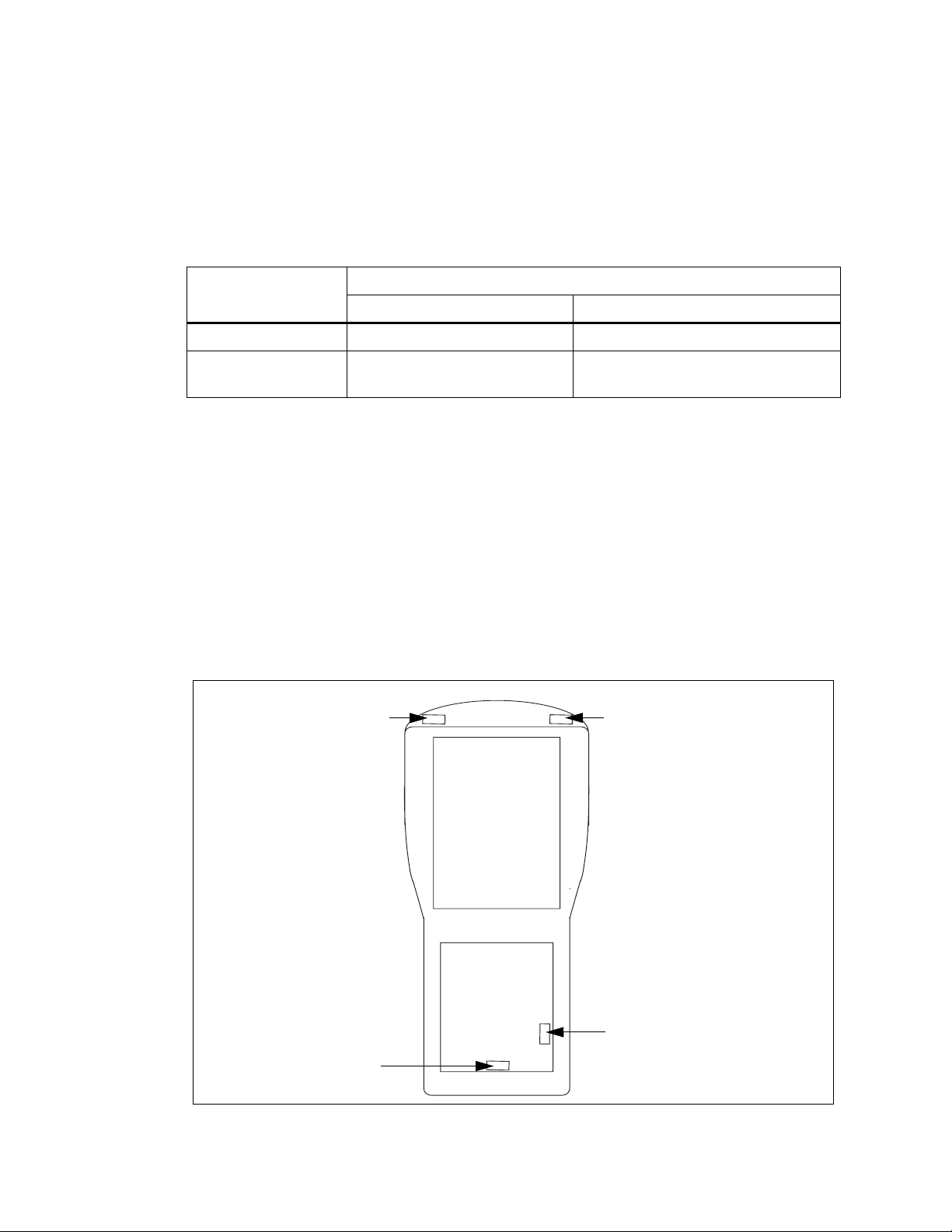
T o access the on/of f switch, remove the endcap. See Figure 2.3 on page 16 for the switch position.
WORKABOUT PRO 2nd. Generation C, and S
T o access the on/off switch, remove the battery cover and remove the batteries. See Figure 2.3 on
page 16 for the switch position.
Figure 2.3 WORKABOUT PRO back view showing the positions of the on/off switch
WORKABOUT PRO C, M, ME
variants (SW1401)
WORKABOUT PRO S variant
(SW1401)
WORKABOUT PRO 2nd.
16 Psion Teklogix WORKABOUT PRO HDK User Manual
Back-
Battery
WORKABOUT PRO 2nd.
Generation S variant (SW1502)

2.10 Connector Locations
The following diagrams show the positions of the electrical connectors on the main logic board for
the WORKABOUT PRO and the WORKABOUT PRO 2nd. Generation computers.
Figure 2.4 Connector Locations On The WORKABOUT PRO C, M, And ME
Chapter 2: Hardware
Connector Locations
100-Pin Connector
Scanner Connector
Figure 2.5 Connector Locations On The WORKABOUT PRO S
Audio Connector
(Not supported in software)
100-Pin Connector
Scanner Connector
Audio Connector
(Not supported in software)
Psion Teklogix WORKABOUT PRO HDK User Manual 17

Chapter 2: Hardware
Connector Locations
Figure 2.6 Connector Locations On The WORKABOUT PRO 2nd. Generation C And S
USB Connector
Audio Connector
100-Pin Connector
Audio Connector
(Not supported in software)
Scanner Connector
18 Psion Teklogix WORKABOUT PRO HDK User Manual

SOFTWARE 3
3.1 Overview.................................................21
3.2 Windows Drivers ............................................21
3.2.1 The Peripheral Control (PCO) Driver............. ... ...... ...... .21
3.2.2 The PCMCIA Driver .....................................21
3.2.3 The Serial Port Driver.....................................21
3.3 Non-PsionTeklogix Drivers.............. ...... ...... ... ...... ....21
3.3.1 Installation...........................................21
3.3.2 Drivers In Windows Mobile 6........... ...... ...... ...... ... .21
3.4 System Initialization . . . . . . . . . . . . . . . . . . . . . . . . . . . . . . . . . . . . . . . . . . . 22
3.5 Registry Keys..............................................22
3.5.2 Registry Settings For Serial Ports . . . . . . . . . . . . . . . . . . . . . . . . . . . . . . . 22
3.5.3 Registry Settings For Psion Teklogix Device Drivers. . . . . . . . . . . . . . . . . . . . . 23
3.5.4 Registry Settings For Non-Psion Teklogix Device Drivers . . . . . . . . . . . . . . . . . . 23
3.5.4.1 Loading Non-PsionTeklogix Device Drivers....................24
3.6 COM Port Assignments.........................................24
3.7 The C++ Application Programming Interface..............................25
3.7.1 Installing The Software....................................25
3.7.2 Development Platforms........... ...... ...... ...... ...... .26
3.7.3 The Interrupts Namespace............................ ...... .26
3.7.4 The ExpansionWakeup Namespace.................... ...... ....26
3.7.5 The GPIO Namespace.....................................26
3.7.6 The EEPROM Namespace ..................................26
3.7.7 The ExpansionUSB Namespace................................26
3.7.8 The USBhub Namespace...................................27
3.7.9 The ScannerPort Namespace.................................27
3.7.10 The smBus Namespace....................................27
3.7.11 The PCMCIA Namespace...... ...... ...... ...... ... ...... .27
Psion Teklogix WORKABOUT PRO HDK User Manual 19

 Loading...