

Page 1

User Guide
Model TFF-2245
TM
WhereTag IV BT
User Guide
Part Numbers:
TFF-2245-00AA
TFF-2246-00AA
User Guide, WhereTag IV BT, TFF-2245 D2025 Rev C
Copyright Zebra Technologies Corporation Confidential and Private
1
Page 2

_
User Guide
Typographical Conventions
WARNING
____________
CAUTION
____________
Warnings call attention to a procedure or practice that could
result in personal injury if not correctly performed. Do not
proceed until you fully understand and meet the required
conditions.
Cautions call attention to an operation procedure or practice that
could damage the product if not correctly performed. Do not
proceed until understanding and meeting these required
conditions.
_________
Note
________
Notes provide information that can be helpful in understanding
the operation of the product.
2
User Guide, WhereTag IV BT, TFF-2245 D2025 Rev C
Copyright Zebra Technologies Corporation Confidential and Private
Page 3

User Guide
REGULA T ORY AGENCY INFORMA TION
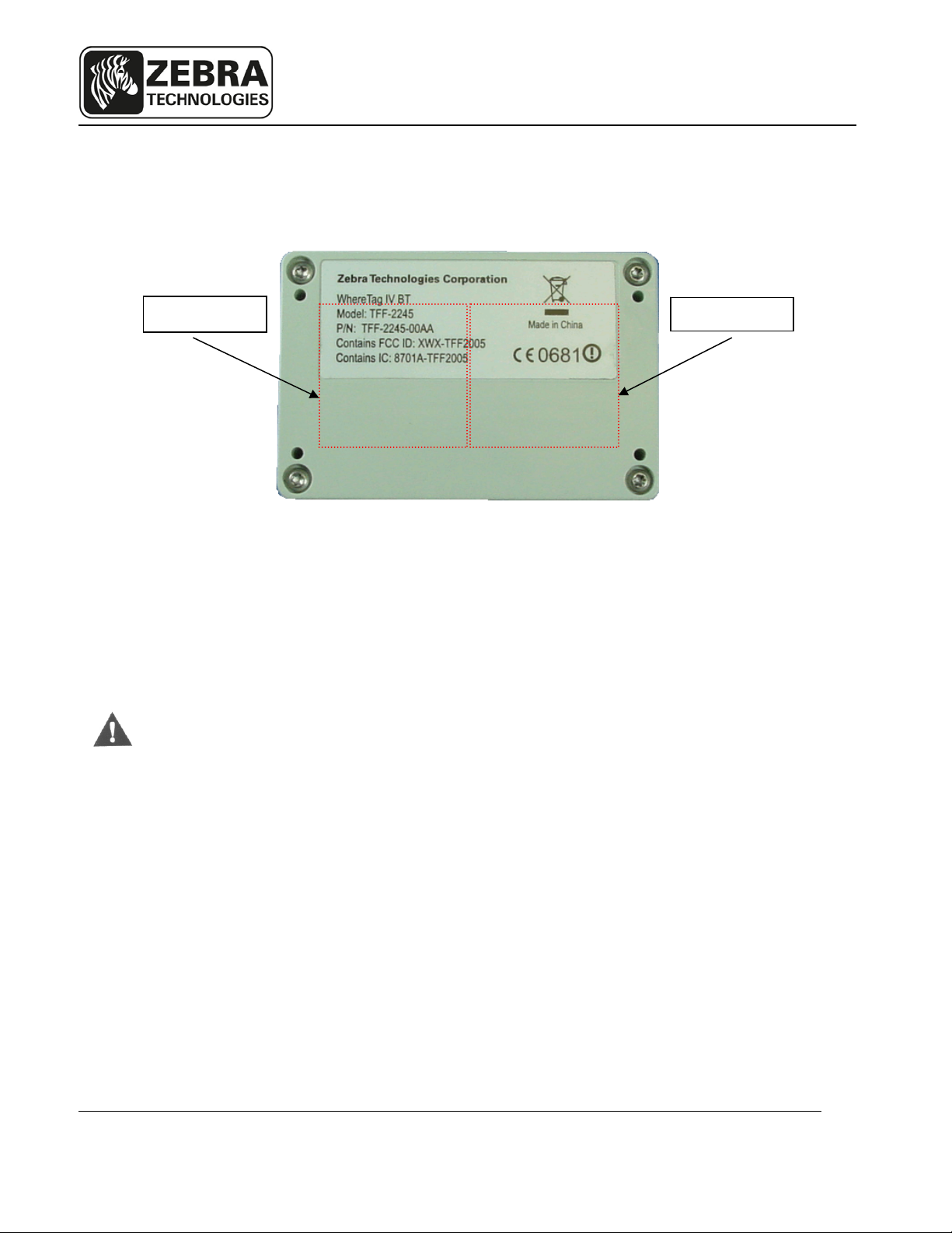
Unless otherwise specified, the following regulatory agency information is for Model
TFF-2245 devices, which include part numbers TFF-2245-00AA, and TFF-2246-00AA.
RF Notice
Any changes or modifications to Zebra Technologies Corporation (ZTC) equipment not
expressly approved by ZTC could void the user’s authority to operate the equipment.
FCC Compliance Statement
This device complies with Part 15 rules. Operation is subject to the following two
conditions:
(1) This device may not cause harmful interference
(2) This device must accept any interference which may cause undesired operation
Contains FCC ID: XWX-TFF2005
This equipment has been tested and found to comply with the limits for both Class A
and Class B devices, pursuant to Part 15 of the FCC Rules & Regulations.
Canadian DOC Compliance Statement
This Class B digital apparatus complies with Canadian ICES-003.
Cet appareil numérique de la classe B est conforme à la norme NMB-003 du Canada.
Contains IC: 8701A-TFF2005
Other Compliance Information
TRA
REGISTERED No:
ER37069/15
DEALER No:
0071480/11
User Guide, WhereTag IV BT, TFF-2245 D2025 Rev C
Copyright Zebra Technologies Corporation Confidential and Private
3
Page 4

User Guide
EU Compliance Information
This Class I radio is approved for use in the following countries
AT BE BG CY CZ DK EE
FI FR DE GR HU IE IT
LV LT LU MT NL PL PT
RO SK SI ES SE GB
IS LI NO CH
User Guide, WhereTag IV BT, TFF-2245 D2025 Rev C
Copyright Zebra Technologies Corporation Confidential and Private
4
Page 5
User Guide
Cautions:
No modifications to the tag allowed. This includes any type of modification to
the case, such as adding metal foils, holes, disassembly or modifications to the
PCB assembly, antenna, battery or modifications to the product labels, etc.
Prior to installation, carefully inspect the tag, looking for crack, puncture or any
other breach of the plastic case. Damaged tags must not be used. Properly
dispose of any damaged tag.
Never dispose of the tag in a fire.
Deactivate the tag when not in use. It is mandatory to deactivate the tag prior
to shipment by airplanes.
Follow limitations of use as set forth by any applicable regulatory bodies.
The tag contains replaceable primary Lithium Thionyl Chloride (Li-SOCl2)
WARNING
batteries, which must be replaced only by trained service technicians. ZTC
offers service to replace the batteries. Please contact your ZTC account
manager for more information.
Do not attempt to open the tag and modify the battery due to fire, explosion and
severe burn hazard. Do not recharge, short circuit, crush, dissemble, heat
above 100 oC (212 oF), incinerate, or expose contents of the battery to water.
Do not dispose the tag or its lithium batteries in unsorted municipal waste. In
most countries, recycling programs are available through non-profit
organization, mandated by local government or organized on a voluntary basis.
Contact your local government for disposal practices in your area. ZTC offers
recycling programs in certain geographic areas. To determine if a program is
available for this product in your area, please refer to our web site at:
http://www.zebra.com/environment.
When not in use, the tag should be stored in dry and cool conditions at a
o
temperature preferably not exceeding +30
C (86 oF).
User Guide, WhereTag IV BT, TFF-2245 D2025 Rev C
Copyright Zebra Technologies Corporation Confidential and Private
5
Page 6
User Guide
Document Revision History
Revision Change Change Description Date Initials
01 Draft 6/29/12 HH
A C03036 Initial Release 1/22/13 HH
B C03181 Updated tag pictures 5/22/13 HH
C LE000530 Add UAE TRA compliance information 2/16/15 HH
User Guide, WhereTag IV BT, TFF-2245 D2025 Rev C
Copyright Zebra Technologies Corporation Confidential and Private
6
Page 7

User Guide
Table of Contents Page
REGULATORYAGENCYINFORMATION........................................................................................................................3
EUCOMPLIANCEINFORMATION............................................................................................................................... .................4
1 OVERVIEW........................................................................................................................................................8
2 ZTCCALLSYSTEMCOMPONENTS.......................................................................................................................9
3 INSTALLATION&MOUNTING...........................................................................................................................11
3.1 POLY‐LOCK................................................................................................................................................................11
3.2 MOUNTINGWHERETAGIVBTWITHPOLY‐LOCK..............................................................................................................12
3.3 FOAMTAPESQUARES..................................................................................................................................................13
3.4 MOUNTINGWHERETAGIVBTWITHFOAMTAPESQUARES................................................................................................14
3.5 MOUNTINGWHERETAGIVBTWITHSNAP‐ONMOUNTANDSCREWS...................................................................................15
3.6 MOUNTINGWHERETAGIVBTWITHVEHICLEREARVIEWMIRRORMOUNT...........................................................................16
4 OPERATIONOFTHEWHERETAGIVBT..............................................................................................................17
4.1 CALLMODE...............................................................................................................................................................17
4.2 SWITCHMODE...........................................................................................................................................................17
4.3 TURNINGWHERETAGIVBTOFF...................................................................................................................................18
5 SPECIFICATIONS:WHERETAGIVBTDEVICE.......................................................................................................19
Table of Figures Page
FIGURE1:POLY‐LOCKFASTENERWITHADHESIVEBACKING................................................................................................................ 11
FIGURE2:POLY‐LOCK&FOAMTAPEPOSITIONS..............................................................................................................................12
FIGURE3:FOAMTAPESQUARES..................................................................................................................................................13
FIGURE4:SNAP‐ONMOUNT.......................................................................................................................................................15
FIGURE5:VEHICLEREARVIEWMIRRORMOUNT.............................................................................................................................16
User Guide, WhereTag IV BT, TFF-2245 D2025 Rev C
Copyright Zebra Technologies Corporation Confidential and Private
7
Page 8

User Guide
1 OVERVIEW
The Zebra Technologies Corporation (ZTC) Call System allows users in manufacturing
and assembly operations to request service for specific parts without leaving their
workstations. Specific parts or service requests may be assigned to individual
WhereTag IV BT devices so that users may indicate which item is needed. For
example, an assembly worker using several parts: each part is associated with a
separate WhereTag IV BT device located in the workstation. By pressing the green
button on the WhereTag IV BT device, a radio signal is sent by the ZTC Call System to
the computer system in the supply area, indicating which workstation requires the
specified part or service. The LED on the front face of the device also flashes for a
programmable duration to indicate that the button has been pushed.
The WhereTag IV BT also operates in an optional SWITCH mode. This mode can be
used to indicate a status; the LED will blink either red or green to indicate a functional
status. The status will toggle each time the button is pressed.
To insure that the ZTC Call system is in constant operation, real-time monitoring using
an “I’m Still Alive” blinking transmission advises the system supervisor of the status of
each WhereTag IV BT device. Battery status is also included in these “I’m still alive”
messages as well as in the switch blinks, as well as in the button initiated blinks.
The WhereTag IV BT may be mounted in a work area with removable fasteners,
double-sided foam tape or with mounting brackets and screws. (Refer to Section 3,
Installation and Mounting).
User Guide, WhereTag IV BT, TFF-2245 D2025 Rev C
Copyright Zebra Technologies Corporation Confidential and Private
8
Page 9

User Guide
2 ZTC CALL SYSTEM COMPONENTS
The ZTC Call System consists of four major components: the WhereTag IV BT device;
a Zebra Location Sensor; Zebra Visibility Server Software (VSS) and a host application
to act on Call requests. This document details only the WhereTag IV BT device.
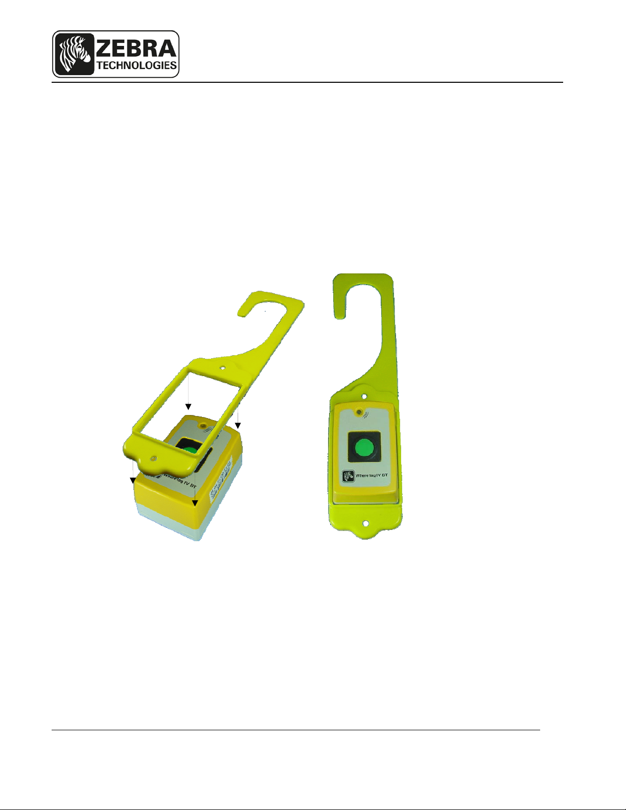
The WhereTag IV BT is a palm-sized device approximately 1.5 inches by 2.5 inches,
1.3 inch thick, in a yellow and gray colored case. A green colored actuator button is in
the center of the device. A light-emitting diode (LED) is located above the button.
The ZTC Location Sensor receives radio signals from the WhereTag IV BT device
when the work station user sends a call requesting parts by pressing the green button
on the WhereTag IV BT. These signals are transferred by cable or wireless to the VSS
server software.
The VSS server software uses the BT tag “blink” signals from the sensors to calculate
the location of the BT tag. A message is generated by VSS and sent to the user’s
computer system indicating that a part is needed at the location of the WhereTag IV BT
device.
If necessary, the WhereWand hand-held communicator can be used to configure the
WhereTag IV BT device. The WhereWand is required to change operating mode or
protocol of the WhereTag IV BT device.
User Guide, WhereTag IV BT, TFF-2245 D2025 Rev C
Copyright Zebra Technologies Corporation Confidential and Private
9
Page 10

User Guide
In addition to the ISO 24730 ZTC Call System, the WhereTag IV BT device will support
operation in a Cisco Certified Extensions (CCX) 802.11b system. The behavior is the
same as in ISO 24730, except that the RF air protocol of the blinks is CCX. The
WhereTag IV BT device also supports DUAL mode, with both ISO 24730 blinks and
CCX blinks being transmitted.
A typical CCX system consists of Light Access Points (LAP), a Wireless LAN Controller
(WLC), a Mobility Services Engine (MSE), and the Wireless Control System (WCS). A
WhereWand allows the user to select the operating protocol of the WhereTag IV BT.
User Guide, WhereTag IV BT, TFF-2245 D2025 Rev C
Copyright Zebra Technologies Corporation Confidential and Private
10
Page 11

User Guide
3 INSTALLATION & MOUNTING
The WhereTag IV BT may be mounted in a work area with removable fasteners,
double-coated foam tape, hanging brackets, or with mounting screws. Overhead
installation is also possible using cable mounting.
Each WhereTag IV BT must be mounted in a location to provide an unobstructed view
in at least one direction. To maintain communication with the Location Sensors, do not
install the WhereTag IV BT inside a metal enclosure such as a metal cabinet.
3.1 Poly-Lock
A plastic, adhesive-backed fastener, Poly-Lock uses mushroom-shaped contact points
that overlap and snap together, forming a strong attachment that can be separated by a
forceful pull. Poly-Lock is not included with the WhereTag IV BT, but is available from
ZTC in precut squares. Contact your ZTC account manager for information, reference
part number TM-204-00 (Poly-Lock Tape, 1” x 1”, Set). Two sets of tape are required
per tag.
Figure 1: Poly-Lock fastener with adhesive backing
User Guide, WhereTag IV BT, TFF-2245 D2025 Rev C
Copyright Zebra Technologies Corporation Confidential and Private
11
Page 12
User Guide
Apply Tape
Apply Tape
Figure 2: Poly-Lock & foam tape positions
3.2 Mounting WhereTag IV BT with Poly-Lock
____________
CAUTION
____________
Do not apply the Poly-Lock when the temperature is below 60F (15C) or
above 90F (32C).
1) Select the desired location in the workstation to mount the WhereTag
IV BT.
2) Clean the mounting surface and the backside of the WhereTag IV BT
with isopropyl alcohol.
3) Select a pair (they are shipped in attached pairs) of Poly-Lock squares,
remove the adhesive backing and press them to the backside of the
tag, sticky side down (see Figure 2).
User Guide, WhereTag IV BT, TFF-2245 D2025 Rev C
Copyright Zebra Technologies Corporation Confidential and Private
12
Page 13

_
User Guide
4) Remove the adhesive backing from an additional pair of Poly-Lock and
affix it adjacent to the first pair as shown in Figure 2.
5) You should now have two pairs of Poly-Lock attached to the backside
of the WhereTag IV BT. Remove the adhesive backing from both
squares.
6) Gently press the WhereTag IV BT against the mounting surface to
assure that the adhesive on the squares is bonded to both surfaces.
3.3 Foam Tape Squares
Foam tape, both sides adhesive, provides a secure, semi-permanent mounting method
for the WhereTag IV BT device. Foam tape is not included with the WhereTag IV BT.
Contact your ZTC Account Manager for information, reference part number TM-202-00
_________
Note
________
(Tape, 1.0” x 1.0”, VHB 4945). Two pieces are required per tag. See figure 2 for foam
tape positions.
Figure 3: Foam tape squares
“Double sticky” tape applies a layer of permanent adhesive film to both surfaces.
Care should be taken in the application of foam tape; once applied it is difficult to
remove.
User Guide, WhereTag IV BT, TFF-2245 D2025 Rev C
Copyright Zebra Technologies Corporation Confidential and Private
13
Page 14

User Guide
3.4 Mounting WhereTag IV BT with Foam Tape Squares
____________
CAUTION
____________
Do not apply the foam tape when the temperature is below 60F (15C) or
above 90F (32C).
1. Select the desired location to mount the WhereTag IV BT.
2. Clean the mounting surface and the backside of the WhereTag IV BT
with isopropyl alcohol.
3. Select two foam tape squares, remove the adhesive backing from one
side only and apply them to the backside of the WhereTag IV BT as
shown in Figure 2.
4. Remove the adhesive backing from the exposed surface of the tape
squares.
5. While holding the WhereTag IV BT, aligned to the desired position.
Gently press the unit onto the mounting surface.
User Guide, WhereTag IV BT, TFF-2245 D2025 Rev C
Copyright Zebra Technologies Corporation Confidential and Private
14
Page 15

User Guide
3.5 Mounting WhereTag IV BT with Snap-on mount and screws
The WhereTag IV BT may be installed using screws by utilizing the snap-on mount (or
ring). The snap-on mount is not included with the WhereTag IV BT. Contact your ZTC
Account Manager for information, reference part number TM-400-00.
SNAP-ON MOUNT
INSTALL
SCREW OR
RIVET
Figure 4: Snap-on mount
1. Firmly push the snap-on mount over the top of the WhereTag IV BT until all 8
of the mount tabs snap into the 8 slots at the 4 corners of the WhereTag IV
BT.
2. Attach the snap-on mount to the desired location using two screws or rivets
(see figure 4).
SLOTS (8X)
INSTALL
SCREW OR
RIVET
User Guide, WhereTag IV BT, TFF-2245 D2025 Rev C
Copyright Zebra Technologies Corporation Confidential and Private
15
Page 16
User Guide
3.6 Mounting WhereTag IV BT with Vehicle Rearview Mirror Mount
The WhereTag IV BT may be installed using a vehicle rearview mirror mount. This
mount is not included with the WhereTag IV BT. Contact your ZTC Account Manager for
information, reference part number TM-206-02.
Figure 5: Snap-on mount
Figure 5: Vehicle Rearview Mirror Mount
1. Firmly push the vehicle rearview mirror mount over the top of the WhereTag
IV BT until all 8 of the mount tabs snap into the 8 slots at the 4 corners of the
WhereTag IV BT.
2. Attach the mount to the rearview mirror of the vehicle.
User Guide, WhereTag IV BT, TFF-2245 D2025 Rev C
Copyright Zebra Technologies Corporation Confidential and Private
16
Page 17

User Guide
4 OPERATION OF THE WHERETAG IV BT
The WhereTag IV BT is a wireless messaging device that is capable of transmitting
simple messages to the ZTC Infrastructure. These messages can range from a call for
parts for line side material replenishment to a request for supervisor assistance. There
are three modes of operation:
Button or CALL Tag Mode
Messaging or SWITCH Tag Mode
PWR OFF Mode
The WhereTag IV BT is shipped in the “PWR OFF” mode. To turn the WhereTag IV BT
on when it is in the OFF mode, press the button once and the tag will resume operation
in either the CALL mode or the SWITCH mode depending on the mode it was in when
the OFF mode was selected.
4.1 Call Mode
In CALL mode the WhereTag IV BT can be used for parts call and other operations that
do not require an indication as to whether the request was fulfilled. In this mode, the
operator presses the button to send the request message, and the WhereTag IV BT will
transmit blinks with “Switch ID 0” which has status 2. The LED on the WhereTag IV BT
will flash amber for 10 seconds. The color, interval, and duration of the LED flashing can
be reconfigured with the WhereWand if desired by the user.
4.2 Switch Mode
In switch mode, the LED toggles between red flashes (OFF) and green flashes (ON).
The normal starting state is OFF. If the operator presses the button, then the Tag will
send a message signaling the change in state and the LED will flash green. The
resulting transmission blink includes “Switch ID 0” which has status 2. The next button
User Guide, WhereTag IV BT, TFF-2245 D2025 Rev C
Copyright Zebra Technologies Corporation Confidential and Private
17
Page 18

User Guide
press will cause a new message to be transmitted with “Switch ID 1” which has status 4.
This signals the change of state, and the LED will change back to flashing red. The
interval and duration of the LED flashing can be reconfigured with the WhereWand if
desired by the user. In the SWITCH mode the WhereTag IV BT will send multiple
transmissions at increasing intervals after each button press. The first set of blinks
occurs as soon as the button is pressed, then repeats at 1 minute after the button press.
The message is then repeated at the following periods after the initial button press: 5
minutes, 10 minutes, 15 minutes, and then 30 minutes.. After completing that
sequences, the WhereTag IV BT then continue sending a set of blinks every 60
minutes.
4.3 Turning WhereTag IV BT Off
The WhereTag IV BT can be switched to the Power OFF mode from either CALL mode
or SWITCH mode. In order to do this, press and hold the button until the LED flashes
rapidly and then release the button. The WhereTag IV BT is now OFF and all
transmissions are disabled. The magnetic receiver in the tag is not disabled.
User Guide, WhereTag IV BT, TFF-2245 D2025 Rev C
Copyright Zebra Technologies Corporation Confidential and Private
18
Page 19

User Guide
5 SPECIFICATIONS: WHERETAG IV BT DEVICE
Specifications are subject to change without notice.
Mechanical
Dimensions 1.33 in x 2.6 in x 1.7 in (3.4 cm x 6.6 cm x 4.35 cm)
Weight 3.1 oz (88 g)
Color High Visibility Yellow and Gray
Attachments Poly-lock, Adhesive Tape, Snap-on Mount, Vehicle Rearview
Mirror Mount
Button
Characteristics
Durability
Drop 4 feet (1.2 meter) to concrete
A green, 0.5-inch diameter membrane switch
Temperature -22°F to +158°F, ( -30° to +70°C )
Humidity 0% to 100% condensing
IP Rating IP 54 (Unit to withstand windblown dust and rain)
Button Functional after 1 million cycles
ESD Functional per IEC-1000-4-2 Level 4
Battery
Battery Type Custom Battery Pack with two “AA” Lithium Thionyl Chloride
Battery Life Typical 7 years (batteries are customer replaceable)
LED Characteristics
Color Amber, Red, and Green
Cells
User Guide, WhereTag IV BT, TFF-2245 D2025 Rev C
Copyright Zebra Technologies Corporation Confidential and Private
19
Page 20

User Guide
ISO 24730 System Operation
Keep Alive Blinks WhereTag IV BT autonomously sends one DSSS blink at
user’s desired blink rate to allow system to verify that the tag
is present and to monitor the tag’s battery health. The
interval can be set from 5 seconds to 5 days with a
WhereWand. (Factory preset: 1 hour)
Switch Blinks The WhereTag IV BT sends a series blinks in response to a
button press. The number of blinks and the interval are user
selectable. The status bits define the desired system action.
(Factory preset: 3 blinks at 5 seconds).
Status Bit 0 xxx0 indicates battery is OK
xxx1 indicates low battery. The batteries should be
replaced.
Status Bit 1 xx0x indicates keep alive blink
xx1x indicates CALL blinks in CALL mode
indicate ON blinks in SWITCH mode
Status Bit 2 x0xx indicates keep alive blink
x1xx indicates OFF blinks in SWITCH mode
CCX System Operation
Beacon Blinks WhereTag IV BT sends one CCX blink at user’s desired blink
rate to allow system to verify tag is present and to monitor
battery health. The interval can be set from 5 seconds to 5
days with a WhereWand. (Factory preset: 1 hour)
Switch
Blinks
The WhereTag IV BT sends a series of CCX blinks
containing the Telemetry Group - Status Sub-group in
response to a button press. The number of blinks, and the
interval are user selectable. The group data content define
the desired system action. (Factory preset: 3 blinks at 5
seconds).
Telemetry Group Status
The telemetry – status group data content is 16-bit Unicode.
‘2’ indicates CALL blinks in CALL mode
indicate ON blinks in SWITCH mode
‘4’ indicates OFF blinks in SWITCH mode
20
User Guide, WhereTag IV BT, TFF-2245 D2025 Rev C
Copyright Zebra Technologies Corporation Confidential and Private
Page 21

User Guide
Configurable Parameters
Mode Call or SWITCH
Protocol ISO 24730, CCX, or Dual (both ISO and CCX
modes).
LED Flashing Rate
and Duration
User defined: Flashing Interval from 1-30 seconds, Duration
from 1 to 900 seconds.
User Guide, WhereTag IV BT, TFF-2245 D2025 Rev C
Copyright Zebra Technologies Corporation Confidential and Private
21
 Loading...