

Page 1
User Guide
Model TFF-2235
WhereCall V and WhereCall V PLC
User Guide
Part Numbers:
TFF-2235-00AA
TFF-2235-00AA-K
TFF-2236-00AA
TFF-2236-00AA-K
____________________________________________________________________________________________ 1
User Guide for WhereCall V and WhereCall V PLC D1722 Rev A
©2008 ZES WhereCall III, WhereCall V and all product names and numbers are ZES trademarks. All other trademarks are the property of their respective owners.
Page 2

User Guide
_
Typographical Conventions
____________
____________
____________
CAUTION
____________
_________
Note
________
Warnings call attention to a procedure or practice that
could result in personal injury if not correctly performed.
Do not proceed until you fully understand and meet the
required conditions.
Cautions call attention to an operation procedure or
practice that could damage the product if not correctly
performed. Do not proceed until understanding and meeting
these required conditions.
Notes provide information that can be helpful in
understanding the operation of the product.
____________________________________________________________________________________________ 2
User Guide for WhereCall V and WhereCall V PLC D1722 Rev A
©2008 ZES WhereCall III, WhereCall V and all product names and numbers are ZES trademarks. All other trademarks are the property of their respective owners.
Page 3

User Guide
REGULA T ORY AGENCY INFORMA TION
Unless otherwise specified, the following regulatory agency information is for Model
TFF-2235 devices, which include part numbers TFF-2235-00AA and TFF-223600AA.
RF Notice
Any changes or modifications to Zebra Enterprise Solution (ZES) equipment not
expressly approved by ZES could void the user’s authority to operate the equipment.
FCC Compliance Statement
This device complies with Part 15 rules. Operation is subject to the following two
conditions:
(1) This device may not cause harmful interference
(2) This device must accept any interference which may cause undesired operation
Contains FCC ID: XWX-TFF2005
This equipment has been tested and found to comply with the limits for both Class A
and Class B devices, pursuant to Part 15 of the FCC Rules & Regulations.
Canadian DOC Compliance Statement
This Class B digital apparatus complies with Canadian ICES-003.
Cet appareil numérique de la classe B est conforme à la norme NMB-003 du
Canada.
Contains IC: 8701A-TFF2005
____________________________________________________________________________________________ 3
User Guide for WhereCall V and WhereCall V PLC D1722 Rev A
©2008 ZES WhereCall III, WhereCall V and all product names and numbers are ZES trademarks. All other trademarks are the property of their respective owners.
Page 4
User Guide
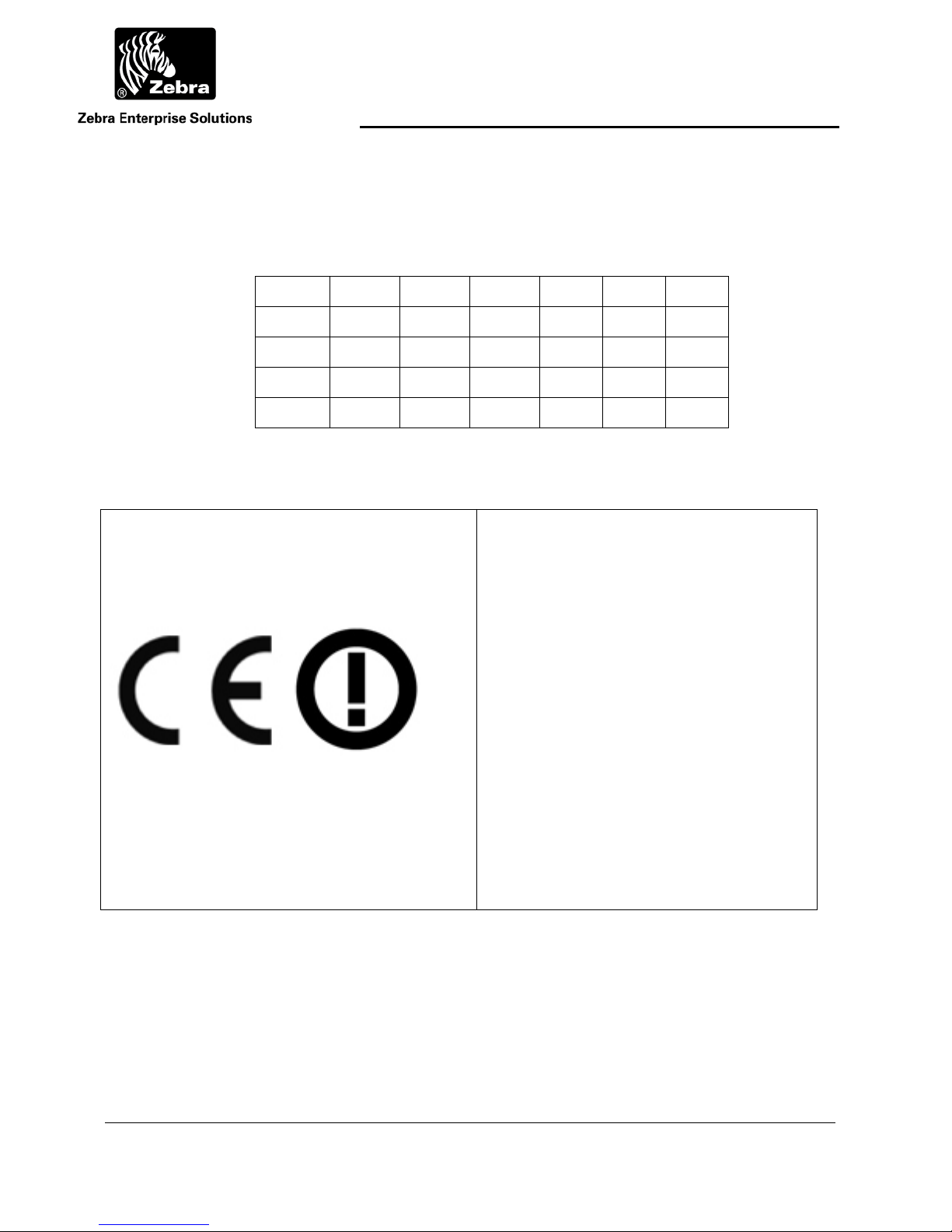
EU Compliance Information
Approved for use in the following countries.
AT BE BG CY CZ DK EE
FI FR DE GR HU IE IT
LV LT LU MT NL PL PT
RO SK SI ES SE GB
IS LI NO CH TR
Note: -Countries there are crossed out there is restrictive use for this
device!
Important Notice:
This RF device is intended for indoor and
outdoor use in all EU and EFTA with the
following limitations.
France: Outdoor use limited to 10 mW e.i.r.p.
within the band 2454-2483.5 MHz
Italy: For private use, a general authorization
is required if WAS/RLAN’s are used outside
own premises. For public use, a general
authorization is required.
Luxembourg: General authorization required
for network and service supply.
Norway: Wideband Data Transmission systems
2400.0-2483.5 MHz does not apply for the
geographical area within a radius of 20 km
from the centre of Ny-Ålesund
____________________________________________________________________________________________ 4
User Guide for WhereCall V and WhereCall V PLC D1722 Rev A
©2008 ZES WhereCall III, WhereCall V and all product names and numbers are ZES trademarks. All other trademarks are the property of their respective owners.
Page 5

User Guide
Document Revision History
Revision Change Change Description Date Initials
A C02338 Initial Release 1/5/11 DBowman
____________________________________________________________________________________________ 5
User Guide for WhereCall V and WhereCall V PLC D1722 Rev A
©2008 ZES WhereCall III, WhereCall V and all product names and numbers are ZES trademarks. All other trademarks are the property of their respective owners.
Page 6

User Guide
Table of Contents Page
REGULATORYAGENCYINFORMATION........................................................................................................................3
1 OVERVIEW........................................................................................................................................................8
2 COMPONENTS...................................................................................................................................................9
3 INSTALLATION&MOUNTING...........................................................................................................................10
3.1 POLY‐LOCK................................................................................................................................................................10
3.2 MOUNTINGWHERECALLVWITHPOLY‐LOCK...................................................................................................................11
3.3 WHERETAGFOAMTAPESQUARES.................................................................................................................................12
3.4 MOUNTINGWHERECALLVWITHFOAMTAPESQUARES.....................................................................................................13
3.5 MOUNTINGWHERECALLVWITHSCREWS.......................................................................................................................15
3.6 HANGINGCABLEBRACKET(TM‐216‐00).......................................................................................................................16
3.7 INSTALLINGWHERECALLVWITHHANGINGCABLEBRACKET...............................................................................................16
4 OPERATIONOFTHEWHERECALLV...................................................................................................................17
4.1 CALLMODE...............................................................................................................................................................17
4.2 SWITCHMODE...........................................................................................................................................................18
4.3 TURNINGWHERECALLVOFF........................................................................................................................................19
4.4 SWITCHINGWHERETAGVMODES.................................................................................................................................19
4.5 CHANGINGSYSTEMPROTOCOLS....................................................................................................................................20
4.6 WHERECALLVSOFTMESSAGES....................................................................................................................................21
5 SPECIFICATIONS:WHERECALLVDEVICE............................................................................................................25
6 WHERECALLVPLCOVERVIEW..........................................................................................................................28
7 WHERECALLVPLCINSTALLATION&MOUNTING..............................................................................................29
8 CONNECTINGTHEWHERECALLVPLC...............................................................................................................30
8.1 WHERECALLVPLCCABLEANDCONNECTOR...................................................................................................................30
8.2 WHERECALLVPLCELECTRICALCONNECTION..................................................................................................................31
8.3 WHERECALLVPLCSWITCHOPERATION.........................................................................................................................33
9 BATTERYREPLACEMENTPROCEDURE...............................................................................................................34
9.1 DESCRIPTION.............................................................................................................................................................34
9.2 REQUIREDMATERIALSANDTOOLS.................................................................................................................................34
9.3 PROCEDURE...............................................................................................................................................................36
____________________________________________________________________________________________ 6
User Guide for WhereCall V and WhereCall V PLC D1722 Rev A
©2008 ZES WhereCall III, WhereCall V and all product names and numbers are ZES trademarks. All other trademarks are the property of their respective owners.
Page 7

User Guide
Table of Figures Page
FIGURE1:POLY‐LOCKFASTENERWITHADHESIVEBACKING................................................................................................................10
FIGURE2:POLY‐LOCK&FOAMTAPEPOSITIONS..............................................................................................................................11
FIGURE3:FOAMTAPESQUARES..................................................................................................................................................12
FIGURE4:SCREWMOUNTINGTEMPLATE(DRAWINGISACTUALSIZE)...................................................................................................14
FIGURE5:COVERSCREWS..........................................................................................................................................................15
FIGURE6:HANGINGCABLEBRACKET,TM‐216‐00.........................................................................................................................16
FIGURE7:FRONT&REARVIEWHANGINGBRACKETINSTALLED...........................................................................................................16
FIGURE8:PHOTOGRAPHOFTHEWHERECALLVPLCWITHANINTERFACECABLEATTACHED....................................................................28
FIGURE9:THEEXTERNALSWITCHISCONNECTEDACROSSPINS1AND3ASINDICATED............................................................................31
FIGURE10ELECTRICALBLOCKDIAGRAM.......................................................................................................................................32
____________________________________________________________________________________________ 7
User Guide for WhereCall V and WhereCall V PLC D1722 Rev A
©2008 ZES WhereCall III, WhereCall V and all product names and numbers are ZES trademarks. All other trademarks are the property of their respective owners.
Page 8

User Guide
1 OVERVIEW
The Zebra Enterprise Solutions (ZES) WhereCall System allows users in manufacturing and
assembly operations to request service or specific parts without leaving their workstations.
Specific parts or service requests may be assigned to individual WhereCall V devices so
that users may indicate which item is needed. For example, an assembly worker using
several parts: Each part is associated with a separate WhereCall V device located in the
workstation. By pressing the green button on the WhereCall V device, a radio signal is sent
by the WhereCall System to the computer system in the supply area, indicating which
workstation requires the specified part or service. The display will first blink CALL , and
then alternate between CALL and the time since the button press. This message can
be customized to site preferences.
The WhereCall V also operates in an optional SWITCH mode. This mode can be used to
indicate a status; the display will blink either -- ON -- or - OFF -- to indicate a functional
status. The status will toggle each time the button is pressed. These messages can also be
customized to site preferences. Each status can display a multi-word message on up to two
different screen buffers.
To insure that the WhereCall system is in constant operation, real-time monitoring using an
“I’m Still Alive” blinking transmission advises the system supervisor of the status of each
WhereCall V device. Battery status is also included in these “I’m still alive” messages as
well as in the switch blinks, as well as in the button initiated blinks.
WhereCall V devices may be individually labeled for identification by applying a usersupplied label to the recessed area on the front panel below the green button.
The WhereCall V may be mounted in a work area with removable fasteners, double-sided
foam tape or with mounting brackets and screws. Overhead installation is also possible by
using cable mounting (Refer to Section 3, Installation and Mounting).
____________________________________________________________________________________________ 8
User Guide for WhereCall V and WhereCall V PLC D1722 Rev A
©2008 ZES WhereCall III, WhereCall V and all product names and numbers are ZES trademarks. All other trademarks are the property of their respective owners.
Page 9

User Guide
2 COMPONENTS
The WhereCall System consists of four major components: the WhereCall V device; a
location antenna; a location processor and a ZES computer server. This document details
only the WhereCall V device.
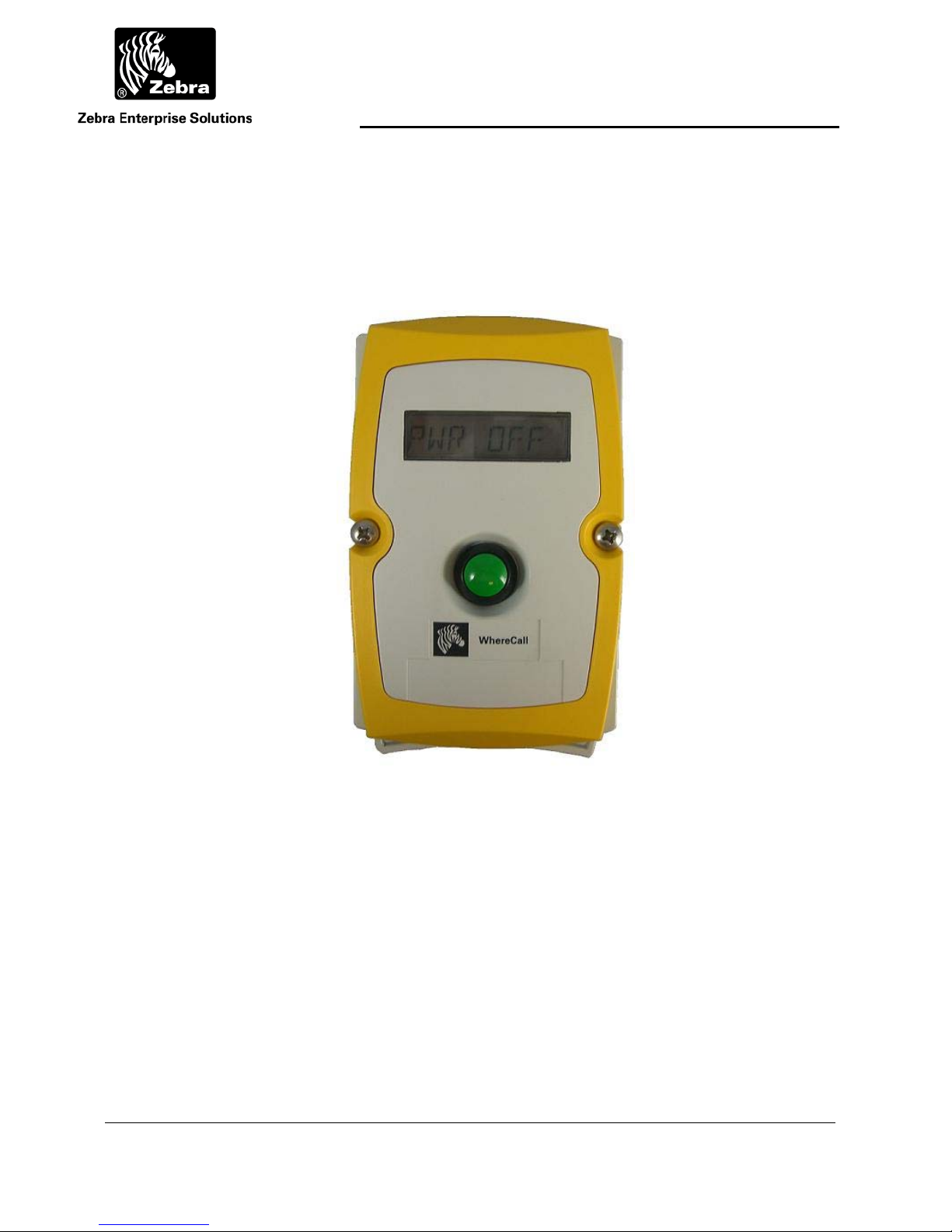
The WhereCall V is a palm-sized device approximately 3 inches by 5 inches, 1 inch thick, in
a yellow and gray colored case. A green colored actuator button is in the center of the
device. A liquid crystal display (LCD) screen is located above the button.
The ZES Location Sensor receives radio signals from the WhereCall V device when the
work station user sends a call requesting parts by pressing the green button on the
WhereCall V. These signals are transferred by cable to the ZES Location Processor.
The ZES Location Processor converts signals from the antenna(s) and sends them to the
ZES computer server. A message is generated by the server and sent to the user’s
computer system indicating that a part is needed at the location of the WhereCall V device.
If necessary, the WhereWand hand-held communicator allows the ZES technician to
configure the WhereCall V device. The WhereWand is not required for most applications.
____________________________________________________________________________________________ 9
User Guide for WhereCall V and WhereCall V PLC D1722 Rev A
©2008 ZES WhereCall III, WhereCall V and all product names and numbers are ZES trademarks. All other trademarks are the property of their respective owners.
Page 10
User Guide
3 INSTALLATION & MOUNTING
The WhereCall V may be mounted in a work area with removable fasteners, double-coated
foam tape, hanging brackets, or with mounting screws. Overhead installation is also
possible using cable mounting.
Each WhereCall V must be mounted in a location to provide an unobstructed view in at least
one direction. To maintain communication with the Location Antennas, do not install the
WhereCall V inside a metal enclosure such as a metal cabinet.
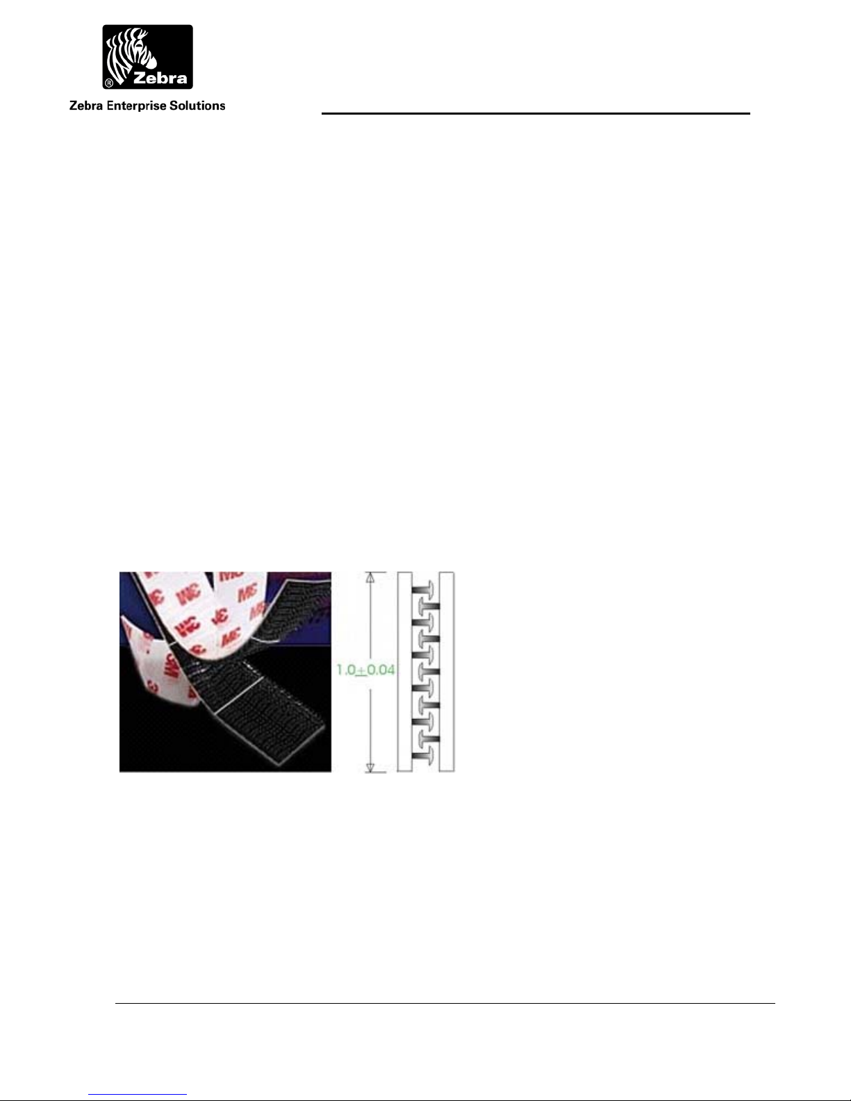
3.1 Poly-Lock
A plastic, adhesive-backed fastener, Poly-Lock uses mushroom-shaped contact points that
overlap and snap together, forming a strong attachment that can be separated by a forceful
pull. Poly-Lock is not included with the WhereCall V, but is available from ZES in precut
squares. Contact your ZES account manager for information.
Figure 1: Poly-Lock fastener with adhesive backing
____________________________________________________________________________________________ 10
User Guide for WhereCall V and WhereCall V PLC D1722 Rev A
©2008 ZES WhereCall III, WhereCall V and all product names and numbers are ZES trademarks. All other trademarks are the property of their respective owners.
Page 11
User Guide
Figure 2: Poly-Lock & foam tape positions
Apply Tape
Apply Tape
3.2 Mounting WhereCall V with Poly-Lock
____________
CAUTION
____________
Do not apply the poly-lock when the temperature is below 60F (15C) or above
90F (32C).
1) Select the desired location in the workstation to mount the WhereCall V.
2) Clean the mounting surface and the back plate of the WhereCall V with
isopropyl alcohol.
3) Select a pair (they are shipped in attached pairs)of Poly-Lock squares,
remove the adhesive backing and press them to the mounting surface,
sticky side down (see Figure 2).
4) Remove the adhesive backing from three additional pairs of Poly-Lock
squares and affix them to the back plate of the WhereCall V to match the
fastener locations on the mounting surface.
____________________________________________________________________________________________ 11
User Guide for WhereCall V and WhereCall V PLC D1722 Rev A
©2008 ZES WhereCall III, WhereCall V and all product names and numbers are ZES trademarks. All other trademarks are the property of their respective owners.
Page 12

User Guide
_
5) You should now have four pairs of Poly-Lock attached to the back of the
WhereCall V. Remove the adhesive backing from all four squares.
6) While holding the WhereCall V, aligned with the fasteners on the
mounting surface. Gently press the unit against the mounting surface to
assure that the adhesive on the squares is bonded to the both surfaces.
3.3 WhereTag Foam Tape Squares
WhereTag foam tape, both sides adhesive, provides a secure, semi-permanent mounting
method for the WhereCall V device. Foam tape is not included with the WhereCall V.
Contact your ZES Account Manager for information.
_________
Note
________
____________________________________________________________________________________________ 12
User Guide for WhereCall V and WhereCall V PLC D1722 Rev A
©2008 ZES WhereCall III, WhereCall V and all product names and numbers are ZES trademarks. All other trademarks are the property of their respective owners.
Figure 3: Foam tape squares
“Double sticky” tape applies a layer of permanent adhesive film to both
surfaces. Care should be taken in the application of foam tape; once applied it
is difficult to remove.
Page 13

3.4 Mounting WhereCall V with Foam Tape Squares
____________
CAUTION
____________
User Guide
Do not apply the foam tape when the temperature is below 60F (15C) or above
90F (32C).
1. Select the desired location to mount the WhereCall V.
2. Clean the mounting surface and the back plate of the WhereCall V with
isopropyl alcohol.
3. Select two foam tape squares, remove the adhesive backing from one
side only and apply them to the back plate of the WhereCall V as shown
in Figure 2.
4. Remove the adhesive backing from the exposed surface of the tape
squares.
5. While holding the WhereCall V, aligned to the desired position. Gently
press the unit onto the mounting surface.
____________________________________________________________________________________________ 13
User Guide for WhereCall V and WhereCall V PLC D1722 Rev A
©2008 ZES WhereCall III, WhereCall V and all product names and numbers are ZES trademarks. All other trademarks are the property of their respective owners.
Page 14

User Guide
Remove cover
screws; Insert #6
Figure 4: Screw mounting template (drawing is actual size).
screws here
Dimension from
center to center of
screws =
2.696”
Housing depth at
screw = 1.10”
____________________________________________________________________________________________ 14
User Guide for WhereCall V and WhereCall V PLC D1722 Rev A
©2008 ZES WhereCall III, WhereCall V and all product names and numbers are ZES trademarks. All other trademarks are the property of their respective owners.
Page 15

User Guide
3.5 Mounting WhereCall V with screws
The WhereCall V may be directly mounted to a surface such as a wall, post, or desk. For
correct screw placement, use the Screw Mounting Template provided in this User’s Guide
(see Figure 4).
Remove cover
screws, replace
with #6 screws
____________
CAUTION
____________
Figure 5: Cover screws
1. Select the desired location to mount the WhereCall V.
2. Position the mounting template on the mounting surface.
3. Place a pencil, pen or metal scribe on the ‘Insert screw here’ points as shown in
Fig. 4, puncture the template and mark the mounting surface.
4. Drill screw pilot holes as needed into the mounting surface.
5. Remove front cover screws as shown in Figure 5.
6. Inserts #6 screws through holes in the front panel of the WhereCall V and gently
tighten to a snug fit (12 to 15 in-ozs). Do not distort case by over-tightening.
Do not over-tighten screws. Damage to the WhereCall V might result if screws
are over-tightened.
____________________________________________________________________________________________ 15
User Guide for WhereCall V and WhereCall V PLC D1722 Rev A
©2008 ZES WhereCall III, WhereCall V and all product names and numbers are ZES trademarks. All other trademarks are the property of their respective owners.
Page 16

User Guide
3.6 Hanging Cable Bracket (TM-216-00)
The WhereCall V may be installed from an overhead cable for ease of use in a workstation
where mounting on flat surfaces is unsafe or inconvenient. Hanging cable brackets are not
included with the WhereCall V but are available from ZES. Contact your ZES Account
Manager for information.
Figure 6: Hanging cable bracket, TM-216-00
3.7 Installing WhereCall V with Hanging Cable Bracket
1. Remove front panel screws as shown in Figure 5. Insert #6 threaded screws
provided with bracket through holes in front panel of WhereCall V.
2. Align the holes in the Hanging Cable Bracket to the screws.
3. Attach hanging cable to Hanging Cable Bracket using cable loop.
Figure 7: Front & rear view hanging bracket installed
____________________________________________________________________________________________ 16
User Guide for WhereCall V and WhereCall V PLC D1722 Rev A
©2008 ZES WhereCall III, WhereCall V and all product names and numbers are ZES trademarks. All other trademarks are the property of their respective owners.
Page 17

User Guide
4 OPERATION OF THE WHERECALL V
The WhereCall V is a wireless messaging device that is capable of transmitting simple
messages to the ZES Infrastructure. These messages can range from a call for parts for
line side material replenishment to a request for supervisor assistance. There are three
modes of operation:
Button or CALL Tag Mode
Messaging or SWITCH Tag Mode
OFF Mode
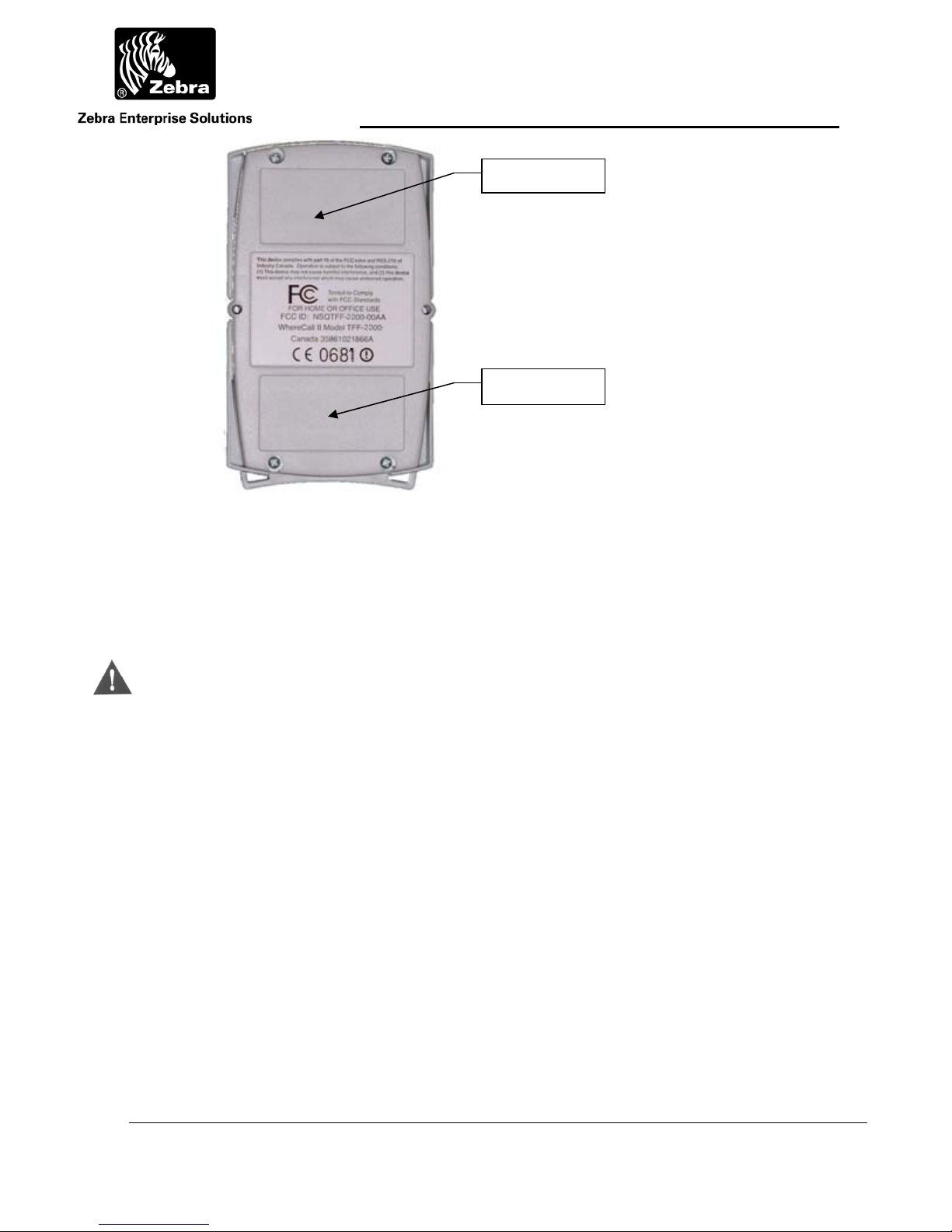
The WhereCall V is shipped in the “OFF” mode. There is also a battery change mode
that is used to condition the tag to for installation of replacement batteries.
When the WhereCall V is on the OFF mode, the display shows PWR OFF . To turn the
WhereCall V on when it is in the OFF mode, press the button once and the tag will
resume operation in either the CALL mode or the SWITCH mode depending on the
mode it was in when the OFF mode was selected.
4.1 Call Mode
In CALL mode the WhereCall V can be used for parts call and other operations that do
not require an indication as to whether the request was fulfilled. In this mode, the
operator presses the button to send the request message, and the WhereCall V will
transmit blinks with “Switch ID 0” which has status 2. The display on the WhereCall V
will flash
was made. This lets the operator easily verify how long it has been since they made their
request. The display is capable of counting up to 9 days, 23 hours, and 59 minutes
shown as
9d23h59m but the elapsed time will not increment any further.
CALL for one minute and then start to count up in minutes since the call
9d23h59m after which it will continue to alternate between CALL and
____________________________________________________________________________________________ 17
User Guide for WhereCall V and WhereCall V PLC D1722 Rev A
©2008 ZES WhereCall III, WhereCall V and all product names and numbers are ZES trademarks. All other trademarks are the property of their respective owners.
Page 18

User Guide
The displayed CALL can be replaced with any other 8-character custom message.
The custom message will blink for one minute after each button push, and then the
custom message will alternate with the elapsed time.
4.2 Switch Mode
In switch mode, the display toggles between -- ON -- and -- OFF --. The normal
starting state is OFF. If the operator presses the button, then the WhereCall will send a
message signaling the change in state and the display will change to -- ON --. The
resulting transmission blink includes “Switch ID 0” which has status 2. The next button
press will cause a new message to be transmitted with “Switch ID 1” which has status 4.
This signals the change of state and the display will change back to - OFF --. In the
SWITCH mode the WhereCall V will send multiple transmissions at increasing intervals
after each button press. The first set of blinks occurs as soon as the button is pressed,
then repeats at 1 minute after the button press. The message is then repeated at the
following periods after the initial button press: 5 minutes, 10 minutes, 15 minutes, and
then 30 minutes.. After completing that sequences, the WhereCall V then continue
sending a set of blinks every 60 minutes.
The displayed -- ON -- and - OFF – messages can be replaced to show any one or a
pair of 8-character custom messages. If the message is replaced with a pair of custom
messages, then the display will not flash, but instead alternate between the pair of
custom messages. When the button is pressed, the display will alternate between the
other pair of messages.
____________________________________________________________________________________________ 18
User Guide for WhereCall V and WhereCall V PLC D1722 Rev A
©2008 ZES WhereCall III, WhereCall V and all product names and numbers are ZES trademarks. All other trademarks are the property of their respective owners.
Page 19

User Guide
4.3 Turning WhereCall V Off
The WhereCall V can be switched to the Power OFF mode from either CALL mode or
SWITCH mode. In order to do this, press and hold the button until the display shows
******** and then release the button. The display will show the tag firmware version
TAG 2109 for a few seconds and then show the PIC Microcontroller firmware PIC 1017
version for a few seconds, the show PWR OFF . Note that the displayed version number
may differ than those shown above. The WhereCall V is now OFF and all transmissions
are disabled. The magnetic receiver in the tag is also disabled.
4.4 Switching WhereTag V Modes
To change modes between CALL mode and Switch mode or visa versa, press and hold the
button. After about 5 seconds, the display will show ********. DO NOT release the button
while the display shows *********, but continue to keep the button depressed until the
display shows:
- CALL ? if the WhereCall V is currently in SWITCH mode
- SWITCH ? if the WhereCall V is currently is CALL mode.
When either of these is displayed, release the button , and then press and release the
button again within five seconds. This will change the operational mode.
If the WhereCall V has been changed from CALL mode to SWITCH mode, the tag will send
SW ID 1 with status 4 and the display will show
- OFF --.
If the WhereCall V has been changed from SWITCH mode to CALL mode, the tag will send
SW ID 0 with status 2 and the display will show CALL .
____________________________________________________________________________________________ 19
User Guide for WhereCall V and WhereCall V PLC D1722 Rev A
©2008 ZES WhereCall III, WhereCall V and all product names and numbers are ZES trademarks. All other trademarks are the property of their respective owners.
Page 20

User Guide
4.5 Changing System Protocols
To change the WhereCall V mode between ISO 24730, CCX, and dual mode, the
WhereCall V must be in OFF mode and display
PWR OFF . Press and hold the button for
several seconds until the display starts to cycle between these options…
ISO MODE, CCX MODE, DUALMODE, and CNG BATT.
To switch to ISO 24730 mode, keep the button pressed until the display is showing
ISO MODE, then release the button, then click the button again to activate the mode. This
mode will disable all CCX blinks and the WhereCall V will only send ISO 24730 blinks. In
ISO 24730 mode, the decimal point in the lower right most corner of the LCD will flash.
To switch to CCX mode, keep the button pressed until the display is showing CCX MODE, then
release the button, then click the button again to activate the mode. This mode will disable
all ISO 24730 blinks and the WhereCall V will only send CCX blinks. In CCX mode, the
apostrophe in the upper left most corner of the LCD will flash.
To switch to dual protocol mode, keep the button pressed until the display is showing
DUALMODE, then release the button, then click the button again to activate the mode. In this
mode, the WhereCall V send both ISO 24730 and CCX blinks. In dual protocol mode, both
the decimal in the lower right most corner and the apostrophe in the upper left most corner
of the LCD will flash.
If the user has inadvertently released the button at the wrong time and the WhereCall V is
displaying the wrong mode, do not click the button again. The tag will timeout and return to
OFF mode and the display will show
PWR OFF . The user can now start the changing
protocol sequence again.
____________________________________________________________________________________________ 20
User Guide for WhereCall V and WhereCall V PLC D1722 Rev A
©2008 ZES WhereCall III, WhereCall V and all product names and numbers are ZES trademarks. All other trademarks are the property of their respective owners.
Page 21

User Guide
4.6 WhereCall V Soft Messages
The WhereCall V supports soft messaging which allows the user to replace the displayed
messages
CALL , - - ON - - and/or - OFF - - with custom messages. Setting or
changing the soft message will require a WhereWand to enter and program the messages
to the WhereCall V magnetically.
If a custom message is configured in CALL mode, then the custom message will be
displayed. , instead of CALL blinking or alternating with elapsed time, There is no
change to the air protocol blink content .
In SWITCH mode, each of the two messages can be replaced with a single message or a
pair of messages.
If custom messages are configured and the WhereCall V is in the SWITCH mode ON state,
instead of - - ON - - blinking, the display will either blink the custom ON mode single
message or alternate between the pair of custom ON mode messages.
If custom messages are configured and the WhereCall V is in the SWITCH mode OFF state,
instead of
- OFF - - blinking, the display will blink either the custom OFF mode single
message or alternate between the pair of custom OFF mode messages.
A variant of WhereCall V, the WhereCall V PLC, provides for automated call requests by
replacing the call button with a sealed connector that can be interfaced to intelligent shop
floor equipment.
The WhereCall V provides long battery life, typically in excess of 5 years. Additionally, the
batteries are replaceable providing a long product life.
____________________________________________________________________________________________ 21
User Guide for WhereCall V and WhereCall V PLC D1722 Rev A
©2008 ZES WhereCall III, WhereCall V and all product names and numbers are ZES trademarks. All other trademarks are the property of their respective owners.
Page 22

User Guide
Display
Message
“CALL ”
(flashing)
CustCall
(flashing)
“CALL ”
10h 42m
(alternating)
CustCall
10h 42m
(alternating)
--“ON --
(flashing)
Cust ON1
(flashing)
Cust ON1
Cust ON2
(alternating)
- “OFF --
(flashing)
CustOFF1
(flashing)
CustOFF1
CustOFF2
(alternating)
********
PWR OFF
Display Meaning Comments Action required
CALL mode button blinks
are being transmitted.
This display follows the
Call” display and indicates
the elapsed time from the
last button press.
This mode will continue for
60 seconds following a
button press.
The time advances from
1m until it reaches
9d23h59m then holds until the
button is pressed again.
None
None
In SWITCH mode, each
SWITCH mode where the
tag will transmit Switch ID
button press will toggle
between
None
0 with tag status 2.
-- ON -- and - OFF --.
In SWITCH mode, each
SWITCH mode where the
tag will transmit Switch ID
button press will toggle
between
None
0 with tag status 4.
-- ON -- and - OFF --.
Indicates that the user has
held the button for several
seconds and the unit will
turn off when released
After the button is release,
the unit will display its
firmware versions before
turning off.
Release the
button to turn the
WhereCall IV off.
Pressing the button will turn
Indicates that the
WhereCall IV is in PWR
OFF mode
the unit on again into the
mode (CALL or SWITCH)
that the unit was in prior to
None
being turned off.
____________________________________________________________________________________________ 22
User Guide for WhereCall V and WhereCall V PLC D1722 Rev A
©2008 ZES WhereCall III, WhereCall V and all product names and numbers are ZES trademarks. All other trademarks are the property of their respective owners.
Page 23

User Guide
Display
Message
CALL ?
SWITCH ?
ISO MODE
CCX MODE
DUALMODE
CNG BATT
(cycling)
CCX MODE
DUALMODE
CNG BATT
ISO MODE
(cycling)
Display Meaning Comments Action required
To change modes release
the button and then press
Indicates that the user has
held the button for several
seconds and can now
change mode from
SWITCH mode to CALL
mode if desired.
the button again within 5
seconds. Pressing the
button again will initiate
CALL mode and issue Call
blinks. Releasing the button
without pressing it again will
Release the
button, then
press the button
again to initiate
“CALL”
operation.
cause the WhereCall IV to
enter OFF mode.
To change modes release
the button and then press
Indicates that the user has
held the button for several
seconds and can now
change mode from CALL
mode to SWITCH mode if
desired.
the button again within 5
seconds. Pressing the
button again will initiate
SWITCH mode and issue
Switch ID 0 blinks. Releasing
the button without pressing it
again will cause the
Release the
button, then
press the button
again to initiate
“SWITCH”
operation.
WhereCall IV to enter OFF
mode.
ISO MODE indicates the
user has pressed and held
the button for several
seconds while in PWR
OFF state and can now put
the tag into ISO 24730
transmit mode
CCX MODE indicates the
user has pressed and held
the button for several
seconds while in PWR
OFF state and can now put
the tag into an unsupported
mode
The display will cycle
between the various protocol
modes and the change
battery mode. The user
must release the button
when the 24730 mode is
shown then click the button
again to activate the mode.
The display will cycle
between the various protocol
modes and the change
battery mode. The user
must release the button
when the desire mode is
shown then click the button
again to activate the mode.
Release the
button, then
press the button
again to turn the
WhereCall IV on
in ISO 24730
mode.
Release the
button, then wait
until the
WhereCall IV
returns to
POWER OFF
mode
____________________________________________________________________________________________ 23
User Guide for WhereCall V and WhereCall V PLC D1722 Rev A
©2008 ZES WhereCall III, WhereCall V and all product names and numbers are ZES trademarks. All other trademarks are the property of their respective owners.
Page 24

User Guide
Display
Message
DUALMODE
CNG BATT
ISO MODE
CCX MODE
(cycling)
CNG BATT
ISO MODE
CCX MODE
DUALMODE
(cycling)
CHANGE
BATTERY
(alternating)
LOW BATT
(alternating)
Display Meaning Comments Action required
DUALMODE indicates the
user has pressed and held
the button for several
seconds while in PWR
OFF state and can now put
the tag into an unsupported
mode
The display will cycle
between the various protocol
modes and the change
battery mode. The user
must release the button
when the desire mode is
shown then click the button
again to activate the mode.
Release the
button, then wait
until the
WhereCall IV
returns to
POWER OFF
mode.
The display will cycle
CNG BATT indicates the user
has pressed and held the
button for several seconds
while in PWR OFF state
and can now put the tag
into battery change mode
between the various protocol
modes and the change
battery mode. The user
must release the button
when CNG BATT is shown
then click the button again to
Release the
button, then
press the button
again to put the
WhereCall IV into
battery change
mode.
activate the mode.
The user should remove the
Indicates that the
WhereCall IV is in battery
change mode.
bottom cover and replace the
batteries within 5 minutes of
starting the mode. To exit
the mode, click the button
Replace batteries
or click the
button to exit the
mode.
again.
Indicates that the
WhereCall IV has detected
a low battery. The user
should enter battery
change mode and change
This message will alternate
or cycle with the existing
messages in either CALL or
SWITCH mode.
Enter battery
change mode
and replace the
batteries.
the batteries.
____________________________________________________________________________________________ 24
User Guide for WhereCall V and WhereCall V PLC D1722 Rev A
©2008 ZES WhereCall III, WhereCall V and all product names and numbers are ZES trademarks. All other trademarks are the property of their respective owners.
Page 25

User Guide
5 SPECIFICATIONS: WHERECALL V DEVICE
Specifications are subject to change without notice.
Mechanical
Dimensions 2.9 x 4.9 x 1.4 Inches (7.8 cm x 12.5 cm x 3.6 cm)
Weight 6.4 Ounces (181.5 g) check the weight
Color High Visibility Yellow and Gray
Attachments Mounting devices
Form Factor Wall Mounted-Rugged Aesthetics
Durability
Drop 4 feet to concrete
Temperature +32°F to +122°F, ( 0° to +50°C )
Humidity 0% to 100% condensing
Pressure Wash Unit to withstand windblown dust and rain (IP 54)
Button Functional after 1 million cycles
ESD Functional per IEC-1000-4-2 Level 4
Battery
Battery Type Two, “AA” Lithium Thionyl Chloride Cells
Battery Life Typical 5 years (Batteries are customer replaceable)
Connector (used with WhereCall V PLC)
Connector Waterproof, 4 pin, mates with Turck RS-44T or compatible..
____________________________________________________________________________________________ 25
User Guide for WhereCall V and WhereCall V PLC D1722 Rev A
©2008 ZES WhereCall III, WhereCall V and all product names and numbers are ZES trademarks. All other trademarks are the property of their respective owners.
Page 26

User Guide
Configurable Parameters
Configuration
Frame
Button Function Push button 1st time, Tag emits 3 DSSS blinks with
Button
Characteristics
Autonomous Transmission
Characteristics Device sends one DSSS blink at user’s desired blink
Purpose Indicates device is present and functional even if no parts
Configurable WhereWand or Hand Held Communicator can vary rate of
Status Word
Some functions can be changed via a WhereWand.
Contact your ZES service representative for more
information.
status bit 1 set (xxlx). Sub-blinks per blink as
configured. The LCD timer starts, counts up to 24:00
and then holds. Push button 2nd time, the timer clears,
cycle starts over.
A green, .47-inch diameter button, with tactile
feedback.
rate. (Factory preset: to send transmission every 128
seconds) with no status bits set (other than low battery
bit, if active).
requested.
autonomous blinks from 2 seconds to 9 hours. Note: The
WhereCall V will not communicate with the HHC if the
display reads “OFF”
Length 4 bits
Battery low bit bit 0 (xxx1), ‘1’ = battery low.
Call mode Button
bit 1 (xx1x), ‘1’ = button 1 pressed.
Push or
Message mode =
“ON”
Message mode =
bit 2 (x1xx), ‘1’ = button 1 pressed.
“OFF”
Timer and Display Characteristics
Number of
8
Characters
Format 14-Segment with apostrophe and decimal for each
character
Function Check previous page
Digit Size .28 inch [7 mm] high
____________________________________________________________________________________________ 26
User Guide for WhereCall V and WhereCall V PLC D1722 Rev A
©2008 ZES WhereCall III, WhereCall V and all product names and numbers are ZES trademarks. All other trademarks are the property of their respective owners.
Page 27

User Guide
Back Lit No
WhereCall V PLC User & Interface Guide
____________________________________________________________________________________________ 27
User Guide for WhereCall V and WhereCall V PLC D1722 Rev A
©2008 ZES WhereCall III, WhereCall V and all product names and numbers are ZES trademarks. All other trademarks are the property of their respective owners.
Page 28

User Guide
6 WHERECALL V PLC OVERVIEW
This document describes how to mount and interface the WhereCall V PLC to your
equipment via the external industrial connector.
The WhereCall V PLC is a variation of the standard WhereCall V. It allows the call tag to be
used with a remote switch in external equipment. The external equipment can “press the
button” to initiate a call. This enables the WhereCall V PLC and the user equipment to
operate unattended and to send a call message via the ZES system.
Figure 8: Photograph of the WhereCall V PLC with an interface cable attached.
(This cable is not included with the WhereCall V PLC.)
For more information regarding the operation and installation of the
WhereCall VPLC, please refer to the WhereCall V User Guide.
In this document the Terms WhereCall V PLC and TFF-2236 are used
interchangeably and will have the same meaning.
____________________________________________________________________________________________ 28
User Guide for WhereCall V and WhereCall V PLC D1722 Rev A
©2008 ZES WhereCall III, WhereCall V and all product names and numbers are ZES trademarks. All other trademarks are the property of their respective owners.
Page 29

User Guide
_
7 WHERECALL V PLC INSTALLATION & MOUNTING
The WhereCall V PLC may be mounted in a work area with removable fasteners, doublecoated foam tape, hanging brackets, or with mounting screws. Overhead installation is also
possible using cable mounting.
Each WhereCall V PLC must be mounted in a location to provide an unobstructed view to a
location antenna in at least one direction. To maintain communication with the Location
Antennas, do not install the WhereCall V PLC inside a metal enclosure such as a metal
_________
Note
________
cabinet.
In selecting the mounting location keep in mind that the cable from the equipment
to the WhereCall V PLC must not exceed 3 meters (10 feet).
____________________________________________________________________________________________ 29
User Guide for WhereCall V and WhereCall V PLC D1722 Rev A
©2008 ZES WhereCall III, WhereCall V and all product names and numbers are ZES trademarks. All other trademarks are the property of their respective owners.
Page 30

User Guide
_
8 CONNECTING THE WHERECALL V PLC
The WhereCall V PLC can be connected to a remotely mounted switch that is used to
initiate a “button blink”. This product works very much like the WhereCall V except that
“button” actuation is provided from another device.
8.1 WhereCall V PLC Cable and Connector.
The TFF-2236 is to be connected using a Turck, RS 4.4T-X cord-set. The length of the
cable is limited to 3.0M (10 feet). When this cord set is used the connection will be
watertight.
This cord-set can be purchased from:
Turck USA
Other Turck locations are listed on the web site.
____________
CAUTION
____________
_________
Note
________
3000 Campus Drive
Minneapolis, MN 55441
1-800-588-8725
WWW.TURCK.COM
The cable length between the TFF-2236 and the remote device must not exceed
3.0 Meters (10 feet).
ZES does not supply the cord sets and connectors for the WhereCall V PLC.
____________________________________________________________________________________________ 30
User Guide for WhereCall V and WhereCall V PLC D1722 Rev A
©2008 ZES WhereCall III, WhereCall V and all product names and numbers are ZES trademarks. All other trademarks are the property of their respective owners.
Page 31

User Guide
_
8.2 WhereCall V PLC Electrical Connection.
Pins one (1) and three (3) are to be connected to the remote switch.
Figure 9: The external switch is connected across pins 1 and 3 as indicated
_________
Use the reference detail on the connector to identify the pin numbers.
Note
________
The connector may not be oriented the same on all units.
____________________________________________________________________________________________ 31
User Guide for WhereCall V and WhereCall V PLC D1722 Rev A
©2008 ZES WhereCall III, WhereCall V and all product names and numbers are ZES trademarks. All other trademarks are the property of their respective owners.
Page 32

User Guide
Remote
device
WhereCall V PLC
Momentary switch
operated by user's
LCD Window
Not Used
4
3
Not Used
1
2
Cord Set, not to
exceed 3
meters
1.The connector on the WhereCall III+ PLC may not be oriented as
Notes:
2. The Cord is not supplied by WhereNet. Please see instructions.
3. The momentary switch will initiate a "button Blink" when it is
closed for 100 milliseconds and then released. The switch must not
remained closed for more than 3.0 seconds or the tag will
transition to the OFF mode .
Figure 10 Electrical Block Diagram
____________
The cable should be connected and routed to prevent large voltage
CAUTION
____________
spikes and static discharges from being carried into the tag via the
switch cable. This may result in false “Button Calls” being generated or
in extreme cases the TFF-2236 could be damaged.
____________________________________________________________________________________________ 32
User Guide for WhereCall V and WhereCall V PLC D1722 Rev A
©2008 ZES WhereCall III, WhereCall V and all product names and numbers are ZES trademarks. All other trademarks are the property of their respective owners.
Page 33

User Guide
_
8.3 WhereCall V PLC Switch Operation
The switch used to operate the TFF-2236 must be a momentary type. The TFF-2236 will
initiate a “Button Blink” sequence when the switch breaks after having been closed for at
least 100 ms and less than 5 seconds. It the switch is closed for less than 100 ms the unit
will not react. See Table 1 for more information.
_________
Note
________
If the switch remains closed for three (3) seconds or more, the unit will change to
the “OFF” mode.
____________________________________________________________________________________________ 33
User Guide for WhereCall V and WhereCall V PLC D1722 Rev A
©2008 ZES WhereCall III, WhereCall V and all product names and numbers are ZES trademarks. All other trademarks are the property of their respective owners.
Page 34

User Guide
9 BATTERY REPLACEMENT PROCEDURE
9.1 Description
WhereCall V Tags have a nominal battery life of 5 years. After that nominal battery life, it is
possible to replace the batteries to extend the life of the tag itself; however, ZES does not
provide personnel or Services for this process.
To avoid damaging the WhereCall V tags, the proper screwdrivers with the correct settings
must be used. This procedure must be followed or the WhereCall V may become nonoperational and there is no field recovery method if this occurs. Batteries should be replaced
before they are completely dead.
ZES assumes no responsibility for damage to or failure of the WhereCall Tags resulting
from this battery replacement procedure.
9.2 Required Materials and Tools
9.2.1 Materials
____________
CAUTION
____________
Qty. 2 per tag 3.6V Lithium battery
(ZES P/N 20057, SAFT P/N LS 14500)
SAFT 12 company address - rue Sadi Carnot 93170 BAGNOLET - France
Tel.: +33 (0)1 49 93 19 18 Fax: +33 (0)1 49 93 19 50
Caution: Use only the exact battery and manufacturer specified above.
Note: It is recommended that new batteries be marked with a marker prior to use to
avoid inadvertent confusion with old batteries while replacement is being done.
____________________________________________________________________________________________ 34
User Guide for WhereCall V and WhereCall V PLC D1722 Rev A
©2008 ZES WhereCall III, WhereCall V and all product names and numbers are ZES trademarks. All other trademarks are the property of their respective owners.
Page 35

User Guide
9.2.2 Tools
One, adjustable torque screwdriver with a # 2 Phillips tip and the torque set to 26 inch
pounds for the two screws on the Face of the tag.
One, adjustable torque screwdriver with a # 1 Phillips tip and the torque set to 6 inch
pounds for the four screws in the back of the tag.
One, “small, pocket size” flat blade screw driver use to remove batteries from the
battery holder.
One, ESD wrist strap or equivalent static protection device.
ZES does not provide the required materials and tools for changing batteries in the
WhereCall V Tags.
____________________________________________________________________________________________ 35
User Guide for WhereCall V and WhereCall V PLC D1722 Rev A
©2008 ZES WhereCall III, WhereCall V and all product names and numbers are ZES trademarks. All other trademarks are the property of their respective owners.
Page 36

User Guide
9.3 Procedure
____________
CAUTION
____________
Caution: Personnel changing batteries must use an ESD wrist strap to prevent
damage of the tag circuit board due to static discharge. Follow the manufacturer’s
instructions for proper use of the static prevention device.
1) To change the WhereCall V batteries, the WhereCall V must be in OFF mode and
display PWR OFF . See section 4.3 for instructions on turning the WhereCall V off.
2) From the OFF mode, enter battery change mode as follows:
Press and hold the button for several seconds until the display starts to cycle
between these options…ISO MODE, CCX MODE, DUALMODE, and CNG BATT. Release
the button when the display shows CNG BATT, then click the button again to
activate the mode. The WhereCall IV is now in a mode that draws more current in
bursts to ensure the circuitry fully discharges when the batteries are removed.
This mode will expire in 5 minutes, so the batteries should be replaced within 5
minutes to ensure proper restart of the internal processors.
3) Proceed with the battery replacement procedure. Use the #2 Phillips screwdriver
to remove the 2 screws from the face of the tag.
4) With the tag sitting face down, use the #1 Phillips screwdriver to remove the 4
screws near the corners on the back of the tag.
5) With the tag face down, grasp the yellow bezel with one hand and remove the
white back cover with the other hand. Place the cover aside with the screw points
down noting the orientation for ease of reassembly. Take care not to invert the
cover as the screws can fall out and may be lost.
____________________________________________________________________________________________ 36
User Guide for WhereCall V and WhereCall V PLC D1722 Rev A
©2008 ZES WhereCall III, WhereCall V and all product names and numbers are ZES trademarks. All other trademarks are the property of their respective owners.
Page 37

User Guide
6) Note the positive/negative orientation of one of the batteries and insert the tip of
the flat blade screw driver between the Positive (+) end of the battery and the
plastic case and gently pry it loose. Insert a new battery insuring the correct
positive/negative orientation before removing the second battery. Replace the
second battery.
Note battery orientation. The arrows
point to the + side of the 2 batteries
____________
CAUTION
____________
7)
8)
9) To restore the tag to operation press the button and the tag will resume normal
Caution: Inserting a battery with the wrong orientation
may damage the batteries and/or the tag
Confirm that the display indicates OFF. This confirms that the battery
replacement was successful.
Reassemble the tag using the screws removed earlier
operation.
.
____________________________________________________________________________________________ 37
User Guide for WhereCall V and WhereCall V PLC D1722 Rev A
©2008 ZES WhereCall III, WhereCall V and all product names and numbers are ZES trademarks. All other trademarks are the property of their respective owners.
 Loading...