

Zebra FS40-SR20D4, VS40-WA20S4, VS70-CM20S5, FS70-CM20F5, VS70-CM20P5 Product Reference Guide
FS/VS Smart
Camera Series
Product Reference Guide
MN-003810-02EN Rev. A

ZEBRA and the stylized Zebra head are trademarks of Zebra Technologies Corporation, registered in
many jurisdictions worldwide. All other trademarks are the property of their respective owners.
©2021 Zebra Technologies Corporation and/or its affiliates. All rights reserved.
Information in this document is subject to change without notice. The software described in this document
is furnished under a license agreement or nondisclosure agreement. The software may be used or copied
only in accordance with the terms of those agreements.
For further information regarding legal and proprietary statements, please go to:
SOFTWARE:zebra.com/linkoslegal
COPYRIGHTS:zebra.com/copyright
WARRANTY:zebra.com/warranty
END USER LICENSE AGREEMENT: zebra.com/eula
Terms of Use
Proprietary Statement
This manual contains proprietary information of Zebra Technologies Corporation and its subsidiaries
(“Zebra Technologies”). It is intended solely for the information and use of parties operating and
maintaining the equipment described herein. Such proprietary information may not be used, reproduced,
or disclosed to any other parties for any other purpose without the express, written permission of Zebra
Technologies.
Product Improvements
Continuous improvement of products is a policy of Zebra Technologies. All specifications and designs are
subject to change without notice.
Liability Disclaimer
Zebra Technologies takes steps to ensure that its published Engineering specifications and manuals are
correct; however, errors do occur. Zebra Technologies reserves the right to correct any such errors and
disclaims liability resulting therefrom.
Limitation of Liability
In no event shall Zebra Technologies or anyone else involved in the creation, production, or delivery of the
accompanying product (including hardware and software) be liable for any damages whatsoever
(including, without limitation, consequential damages including loss of business profits, business
interruption, or loss of business information) arising out of the use of, the results of use of, or inability to
use such product, even if Zebra Technologies has been advised of the possibility of such damages. Some
jurisdictions do not allow the exclusion or limitation of incidental or consequential damages, so the above
limitation or exclusion may not apply to you.
2

Contents
Getting Started
xS40 Configurations .............................................................................................................. 2
xS70 Configurations .............................................................................................................. 4
FS/VS Smart Camera Accessories ....................................................................................... 5
External Lighting ................................................................................................................. 5
Internal Ring Lighting (xS40 Only) ...................................................................................... 7
Internal and External Filters ................................................................................................ 9
Internal Filters (xS40 Only) ............................................................................................... 11
C-Mount Lenses (xS70 Only) ............................................................................................ 12
Lens Covers (xS70 Only) .................................................................................................. 12
Communication Cables ..................................................................................................... 13
Brackets ............................................................................................................................ 15
Power Supplies ................................................................................................................. 16
FS/VS Smart Camera Specifications .................................................................................. 17
xS40 Specifications .......................................................................................................... 17
xS70 Specifications ....................................................................................................................... 19
Installation
Dimensional Drawings ........................................................................................................ 21
xS40 Dimensional Drawings ............................................................................................. 21
xS70 Dimensional Drawings ............................................................................................. 23
Connection Interfaces ......................................................................................................... 24
xS40 Connections ............................................................................................................. 24
xS70 Connections ............................................................................................................... 25
Torque Specification ......................................................................................................... 26
Power Sources .................................................................................................................... 27
12 Pin M12 Power Input ................................................................................................... 27
Power Over Ethernet ........................................................................................................ 27
USB Type C ...................................................................................................................... 27
Grounding for Electro-Magnetic Compliance and ESD Safe .............................................. 28
Cable Pin Outs .................................................................................................................... 29
Power and I/O Connector ................................................................................................. 29
Ethernet Connector ........................................................................................................... 30
External Light Connector .................................................................................................. 31
Setting up an FS/VS Smart Camera ................................................................................... 32
3

Contents
General Mounting Instructions .......................................................................................... 32
Mounting the Device Using the L-Bracket Accessory (BRKT-LMNT-U000) ..................... 32
Illumination System Installation (xS40 Only) ....................................................................... 35
Illumination System Disassembly (xS40 Only) .................................................................... 35
Threaded Lens Cover Assembly Installation ....................................................................... 36
C-Mount Lens Installation (xS70 Only) ............................................................................... 36
Setting Focus .................................................................................................................... 38
USB Type C ........................................................................................................................ 39
Supported Display Resolutions ......................................................................................... 39
User Interface ...................................................................................................................... 40
Decode LEDs .................................................................................................................... 40
User Interface Label ......................................................................................................... 41
LED and Beeper Indicators ................................................................................................. 42
User Interface Framework Codes ..................................................................................... 44
Data Capture ....................................................................................................................... 47
Aiming Patterns ................................................................................................................ 47
xS40 Decode Ranges ....................................................................................................... 47
xS70 Minimum Focus Distances ....................................................................................... 48
General Purpose Input and Outputs ................................................................................... 48
Optically Coupled GPIO .................................................................................................... 48
Digital Industrial GPIO ...................................................................................................... 50
Analog Output ................................................................................................................... 51
Power and Thermal Management ....................................................................................... 52
Zebra Aurora Software Overview
Human-Machine Interface (HMI) ....................................................................................... 53
Industrial Ethernet Information .......................................................................................... 53
Zebra Aurora Features ........................................................................................................ 53
Device Discovery ................................................................................................................ 54
Ethernet Setup .................................................................................................................. 56
Configuring Device Settings ................................................................................................ 57
Communication Settings ................................................................................................... 58
General Settings ............................................................................................................... 59
GPIO Mapping .................................................................................................................. 60
Building and Deploying Fixed Scanning (FS) Jobs ............................................................. 61
Building and Deploying Vision System (VS) Jobs ............................................................... 62
Using the QuickDraw Tool ................................................................................................ 62
Accessing the Web Human-Machine Interface (HMI) ......................................................... 64
Live Monitoring with the Web HMI .................................................................................... 65
Accessing the Device using the Web-HMI ........................................................................ 66
Factory Reset ...................................................................................................................... 67
Software License Activation Methods ................................................................................. 68
Supported Symbologies ...................................................................................................... 69
Machine Vision Toolsets ..................................................................................................... 69
4

Troubleshooting
Maintenance
Contents
Communicating with the Device .......................................................................................... 72
Pinging the Device via IP .................................................................................................. 72
Pinging the Device via Hostname ..................................................................................... 72
Device Discovery Troubleshooting Methods ....................................................................... 73
Factory Reset the Device .................................................................................................. 73
Power Cycling the Device ................................................................................................. 73
Security Settings ................................................................................................................. 74
Zebra Aurora Communication Port Usage .......................................................................... 75
Maintenance ........................................................................................................................ 76
Known Harmful Ingredients ............................................................................................... 76
Approved Cleaning Agents ............................................................................................... 76
Tolerable Industrial Fluids and Chemicals ................................................................................. 77
Cleaning the Device .......................................................................................................... 77
5

About This Guide
The FS/VS Smart Camera Series Product Reference Guide provides general instructions for integrating,
setting up, and programming the device.
Service Information
If you have a problem with your equipment, contact Zebra Global Customer Support for your region.
Contact information is available at: zebra.com/support
When contacting support, please have the following information available:
• Serial number of the unit
• Model number or product name
• Software type and version number.
Zebra responds to calls by email, telephone or fax within the time limits set forth in support agreements.
If your problem cannot be solved by Zebra Customer Support, you may need to return your equipment for
servicing and will be given specific directions. Zebra is not responsible for any damages incurred during
shipment if the approved shipping container is not used. Shipping the units improperly can possibly void
the warranty.
.
If you purchased your Zebra business product from a Zebra business partner, contact that business
partner for support.
1

Getting Started
This section outlines the configurations, accessories, and specifications of the FS/VS Smart Camera
Series.
xS40 Configurations
Table 1 xS40 Configurations
Model SKU Toolset Focus Range Res. Illumination
FS40 Standard Range
FS40-SR20D4-2C00W DPM with Fast 2D
Decoder
Ethernet with PoE,
Serial, USB and
Industrial Protocols
FS40-SR20D4-3X00W DPM with Fast 2D
Decoder
Ethernet with PoE,
Serial, USB and
Industrial Protocols
FS40-SR20D4-6C00W DPM with Fast 2D
Decoder
Ethernet with PoE,
Serial, USB and
Industrial Protocols
FS40-SR20F4-2C00W Fast 2D Decoder
Ethernet with PoE,
Serial, USB and
Industrial Protocols
FS40-SR20F4-5C00W Fast 2D Decoder
Ethernet with PoE,
Serial, USB and
Industrial Protocols
FS40-SR20F4-6C00W Fast 2D Barcode
Decoder
Ethernet with PoE,
Serial, USB and
Industrial Protocols
Auto Standard
Range
Auto Standard
Range
Auto Standard
Range
Auto Standard
Range
Auto Standard
Range
Auto Standard
Range
2.3 MPRed Illumination
No Filter
2.3 MPWhite Illumination
RGB Filter
2.3 MPRed, White and
Infrared
Illumination
No Filter
2.3 MPRed Illumination
No Filter
2.3 MPInfrared
Illumination
No Filter
2.3 MPRed, White and
Infrared
Illumination
No Filter
2

Getting Started
Table 1 xS40 Configurations
Model SKU Toolset Focus Range Res. Illumination
FS40-SR20Z4-2C00W Standard 2D
Barcode Decoder
Ethernet with PoE,
Serial, USB and
Industrial Protocols
FS40 Wide Angle
FS40-WA20D4-2C00W DPM with Fast 2D
Decoder
Ethernet with PoE,
Serial, USB and
Industrial Protocols
FS40-WA20D4-3X00W DPM with Fast 2D
Decoder
Ethernet with PoE,
Serial, USB and
Industrial Protocols
FS40-WA20D4-6C00W DPM with Fast 2D
Decoder
Ethernet with PoE,
Serial, USB and
Industrial Protocols
FS40-WA20F4-2C00W Fast 2D Barcode
Decoder
Ethernet with PoE,
Serial, USB and
Industrial Protocols
FS40-WA20F4-5C00W Fast 2D Barcode
Decoder
Ethernet with PoE,
Serial, USB and
Industrial Protocols
FS40-WA20F4-6C00W Fast 2D Barcode
Decoder
Ethernet with PoE,
Serial, USB and
Industrial Protocols
FS40-WA20Z4-2C00W Standard 2D
Barcode Decoder
Ethernet with PoE,
Serial, USB and
Industrial Protocols
VS40 Standard Range
VS40-SR20S4-2C00W Sensor Toolset
Ethernet with PoE,
Serial, USB and
Industrial Protocols
VS40-SR20S4-2R00W Sensor Toolset
Ethernet with PoE,
Serial, USB and
Industrial Protocols
Auto Standard
Range
Auto Wide
Angle
Auto Wide
Angle
Auto Wide
Angle
Auto Wide
Angle
Auto Wide
Angle
Auto Wide
Angle
Auto Wide
Angle
Auto Standard
Range
Auto Standard
Range
2.3 MPRed Illumination
No Filter
2.3 MPRed Illumination
No Filter
2.3 MPWhite Illumination
RGB Filter
2.3 MPRed, White, and
Infrared
Illumination
No Filter
2.3 MPRed Illumination
No Filter
2.3 MPInfrared
Illumination
No Filter
2.3 MPRed, White, and
Infrared
Illumination
No Filter
2.3 MPRed Illumination
No Filter
2.3 MPRed Illumination
No Filter
2.3 MPRed Illumination
Red Bandpass
Filter
3

Table 1 xS40 Configurations
Model SKU Toolset Focus Range Res. Illumination
VS40 Wide Angle
VS40-WA20S4-2C00W Sensor Toolset
VS40-WA20S4-2R00W Sensor Toolset
xS70 Configurations
Table 2 xS70 Configurations
Model SKU Toolset Res. Illumination
FS70 FS70-CM20D5-0C00W DPM with Fast 2D Barcode
FS70-CM20F5-0C00W Fast 2D Barcode Decoder
VS70 VS70-CM20S5-0C00W Sensor Toolset
VS70-CM20P5-0C00W DPM with Fast 2D Barcode
Getting Started
Auto Wide
Ethernet with PoE,
Serial, USB and
Industrial Protocols
Auto Wide
Ethernet with PoE
Serial, USB and
Industrial Protocols
Decoder
Dual Ethernet (1 PoE), Serial,
USB and Industrial Protocols
Dual Ethernet (1 PoE), Serial,
USB and Industrial Protocols
Dual Ethernet (1 PoE), Serial,
USB and Industrial Protocols
Decoder
Dual Ethernet (1 PoE), Serial,
USB and Industrial Protocols
2.3 MPRed Illumination
Angle
2.3 MPRed Illumination
Angle
2.3 MP Lens Not Included
2.3 MP Lens Not Included
2.3 MP Lens Not Included
2.3 MP Lens Not Included
No Filter
Red Bandpass
Filter
4
Getting Started
FS/VS Smart Camera Accessories
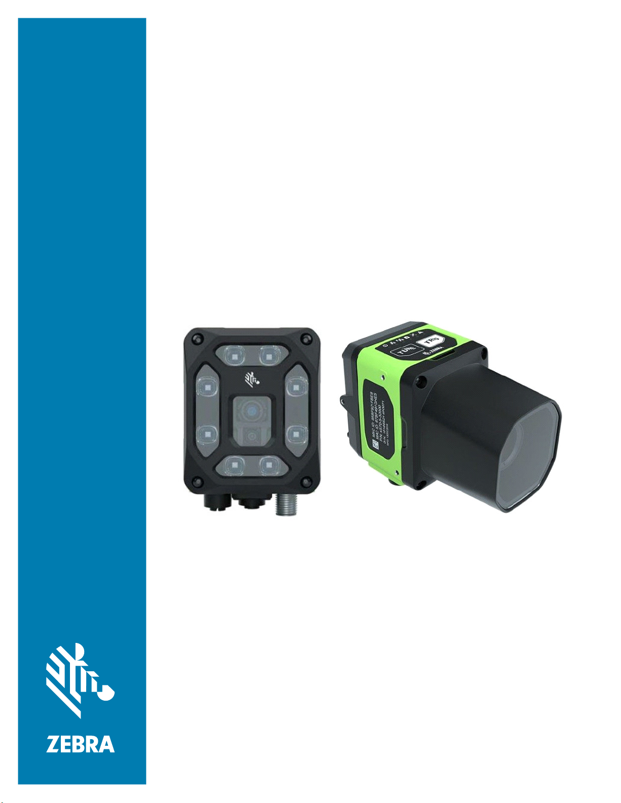
External Lighting
Table 3 External Lighting Accessories
Part Number Description
LGHT-B100RD-0000 LED Bar light, 100MM, red-625
wavelength, 5-Pin male M12 connector,
semi-diffused, includes transparent and
opaque diffusers
LGHT-B100BL-0000 LED Bar light, 100MM, blue-465
wavelength, 5-Pin male M12 connector,
semi-diffused, includes transparent and
opaque diffusers
LGHT-B100WH-0000 LED Bar light, 100MM, white wavelength,
5-Pin male M12 connector, semi-diffused,
includes transparent and opaque diffusers
LGHT-B100IR-0000 LED Bar light, 100MM, IR-850 wavelength,
5-Pin male M12 connector, semi-diffused,
includes transparent and opaque diffusers
LGHT-B300RD-0000 LED Bar light, 300MM, red-625
wavelength, 5-Pin male M12 connector,
semi-diffused, includes transparent and
opaque diffusers.
LGHT-B300BL-0000 LED Bar light, 300MM, blue-465
wavelength, 5-Pin male M12 connector,
semi-diffused, includes transparent and
opaque diffusers.
LGHT-B300WH-0000 LED Bar light, 300MM, white wavelength,
5-Pin male M12 connector, semi-diffused,
includes transparent and opaque diffusers.
LGHT-B300IR-0000 LED Bar light, 300MM, IR-850 wavelength,
5-Pin male M12 connector, semi-diffused,
includes transparent and opaque diffusers.
5

Getting Started
Table 3 External Lighting Accessories (Continued)
Part Number Description
Rings
LGHT-R100BL-0000 LED Ring light, 100MM, blue-465
wavelength, 5-Pin male M12 connector,
semi-diffused, includes transparent and
opaque diffusers.
LGHT-R100WH-0000 LED Ring light, 100MM, white wavelength,
5-Pin male M12 connector, semi-diffused,
includes transparent and opaque diffusers.
LGHT-R100IR-0000 LED Ring light, 100MM, IR-850
wavelength, 5-Pin male M12 connector,
semi-diffused, includes transparent and
opaque diffusers.
LGHT-R100RD-0000 LED Ring light, 100MM, red-625
wavelength, 5-Pin male M12 connector,
semi-diffused, includes transparent and
opaque diffusers.
Polarizers
LGHT-A100BP-0000 100MM Bar Light Polarizer
For use with 100mm External Light Bars
(LGHT-B100xx-0000).
Not for use with IR-850 wavelengths or
when IR image capture is required.
LGHT-A300BP-0000 300MM Bar Light Polarizer
For use with 300mm External Light Bars
(LGHT-B300xx-0000).
Not for use with IR-850 wavelengths or
when IR image capture is required.
LGHT-A100RP-0000 Light Polarizer
For use with 100mm External Ring Lights
(LGHT-R100xx-0000).
Not for use when IR image capture is
required.
6
Getting Started
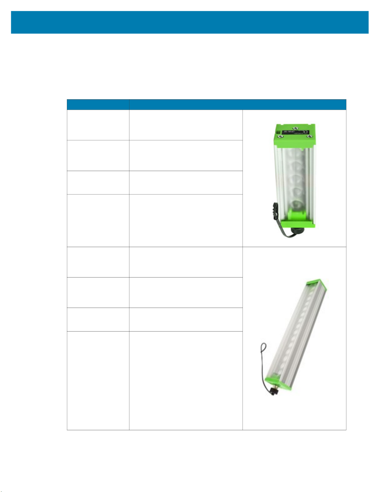
Internal Ring Lighting (xS40 Only)
Table 4 Internal Ring Lighting
Part Number Description
ZLED-XS40WH-0000 xS40 Internal Ring Light, White LED
For use with 100mm External Ring
Lights (LGHT-R100xx-0000).
Not for use when IR image capture
is required.
ZLED-XS40RD-0000 xS40 Internal Ring Light, Red LED
Red lighting is typically used to
capture images on paper.
ZLED-XS40IR-0000 FS40/VS40 Internal Ring Light, IR
LED
IR lighting is typically used in
environments where users do not
want to see any external lighting,
when detecting clear liquids, or
when inspecting produce.
ZLED-XS40MC-0000 FS40/VS40 Internal Ring Light,
Multi-Color - White, Red, Blue, IR
LED
White LEDs are controllable in
individual banks of 4 LEDs.
IR and Red are controllable in
individual banks of 2 LEDs.
7
Getting Started
Table 4 Internal Ring Lighting
Part Number Description
Replacement Ring Light Covers
ZLED-XS40PW-0000 Integrated Light Cover
(Replacement) Cross Polarizer
For use with Wide Angle (WA) xS40
configurations only.
Not for use when IR image capture
is required.
ZLED-XS40PS-0000
ZLED-XS40CW-0000 Integrated Light Cover
ZLED-XS40CS-0000
Integrated Light Cover
(Replacement) Cross Polarizer
For use with Standard Range (SR)
xS40 configurations only.
Not for use when IR image capture
is required.
(Replacement)
For use with Wide Angle (WA) xS40
configurations only.
Integrated Light Cover
(Replacement)
For use with Standard Range (SR)
xS40 configurations only.
8
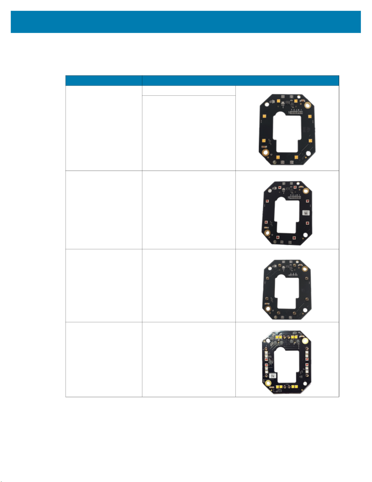
Internal and External Filters
Table 5 Internal and External Filters
Part Number Description Compatibility
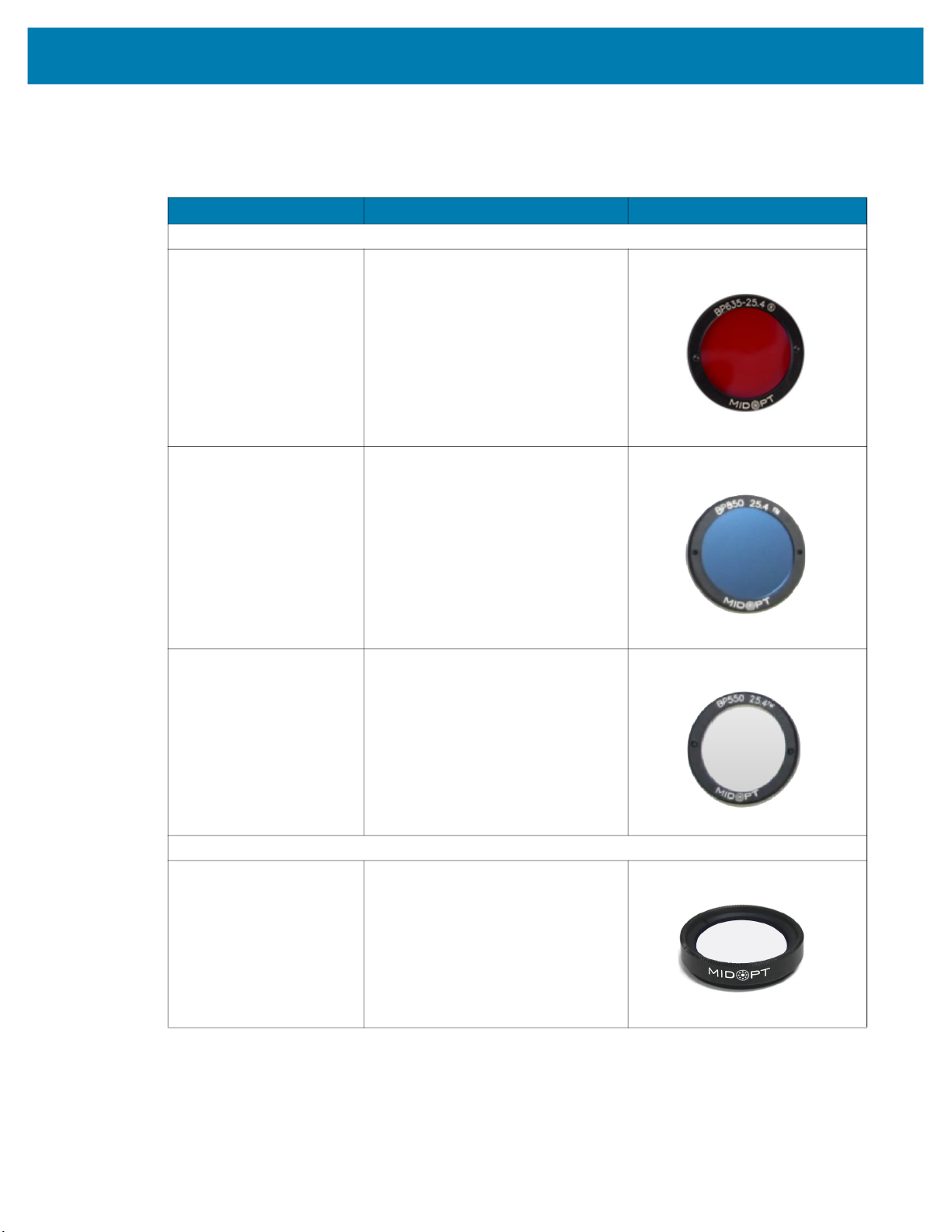
Internal Filters (In Between C-Mount Lens and Imager - xS70 Only)
FLTR-BP635-25400 Red Bandpass Filter, 635NM, 25.4MM
FLTR-BP850-25400 IR Bandpass Filter, 850NM, 25.4MM
Getting Started
For use between C-mount lens and
imager.
For use between C-mount lens and
imager
FLTR-BP550-25400 IR/UV Block Bandpass Filter, 550NM,
25.4MM
For use between C-mount lens and
imager.
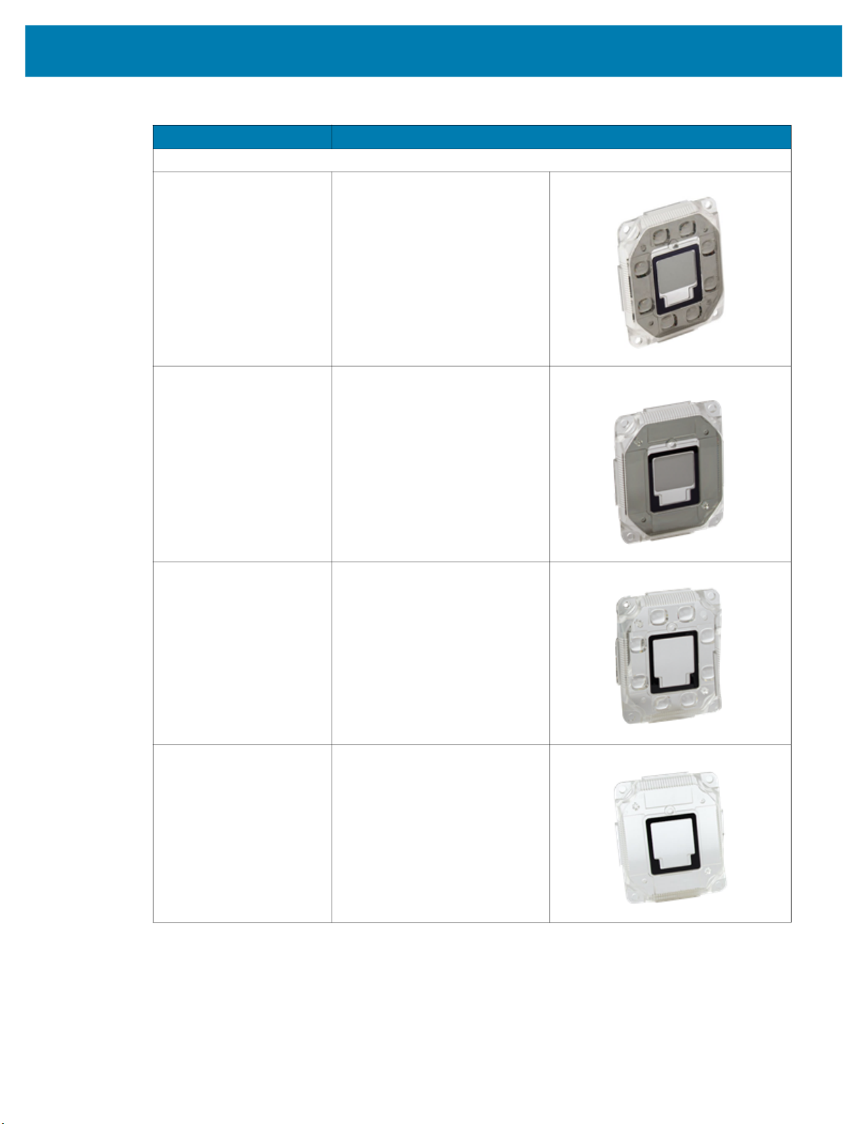
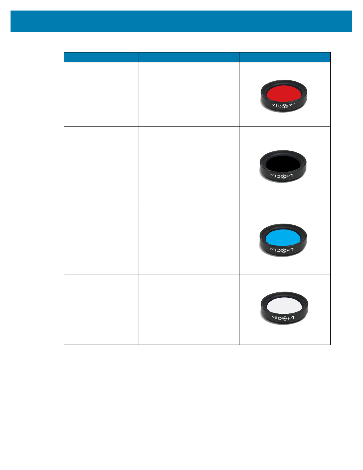
External Filters (on the End of the C-Mount Lens - xS70 Only)
FLTR-BP550-25500 IR/UV Block B Filter, 550NM, 25.4MM
For use on the end of the C-mount lens.
9
Getting Started
Table 5 Internal and External Filters
Part Number Description Compatibility
FLTR-BP635-25500 Red Bandpass Filter, 635NM, 25.4MM
For use on the end of the C-mount lens.
FLTR-BP850-25400 IR Bandpass Filter, 850NM, 25.4MM
For use on the end of the C-mount lens.
Not for use with IR lighting.
FLTR-BP470-25500 Blue Bandpass Filter, 470NM, 25.5MM
For use on the end of the C-mount lens.
FLTR-PZ120-25500 Ultra High Contrast Polarizer Filter,
25.4MM
For use on the end of the C-mount lens.
Not for use with IR lighting.
10
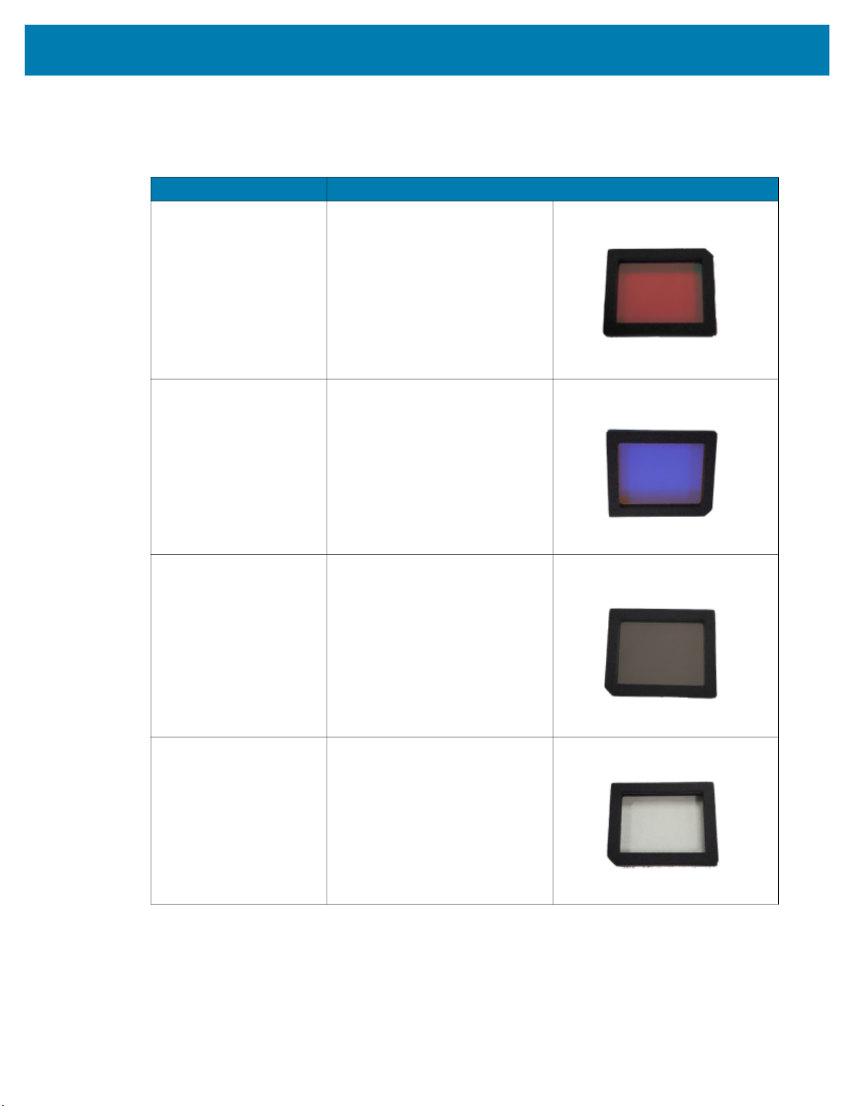
Internal Filters (xS40 Only)
Table 6 Internal Filters
Part Number Description
ZFLT-XS40RD-0000 Red Bandpass Zebra Filter
ZFLT-XS40BL-0000 Blue Bandpass Zebra Filter
Getting Started
ZFLT-XS40IR-0000 IR Bandpass Zebra Filter
ZFLT-XS40MC-0000 IR Blocker Zebra Filter
11
C-Mount Lenses (xS70 Only)
Table 7 External Lenses (xS70)
Part Number Description
LENS-M0800-0100 C-mount Lens
8MM focal length, 25.5 filter thread
LENS-M1200-0100 C-mount Lens
12MM focal length, 25.5 filter thread
LENS-M1600-0100 C-mount Lens
16MM focal length, 25.5 filter thread
LENS-M2500-0100 C-mount Lens
25MM focal length, 25.5 filter thread
LENS-M3500-0100 C-mount Lens
35MM focal length, 25.5 filter thread
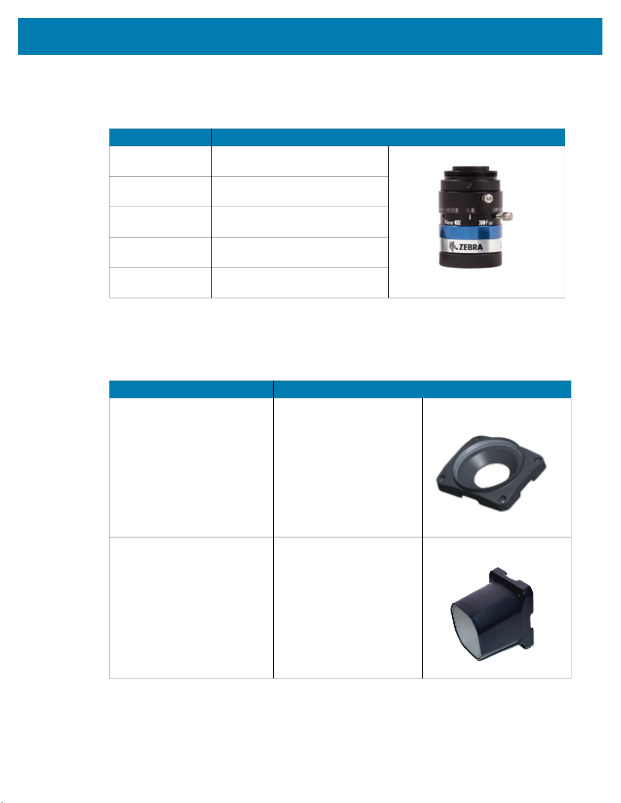
Lens Covers (xS70 Only)
Getting Started
Table 8 xS70 Lens Covers
Part Number Description
LENS-XTC70-0000
LENS-XRC70-0000 Replacement IP67 Lens Cover
Threaded Lens Cover Adapter
12

Communication Cables
Table 9 Cables
Part Number Description Compatibility
USB Cables
CBL-USB02000-USC00 USB 2M, IP67 locking USB-C to USB C,
CBL-USB04000-USC00 USB 4M, IP67 locking USB-C to USB C
Getting Started
SuperSpeed
Compatible with all FS/VS devices.
Compatible with all FS/VS devices.
CBL-USB02000-USA00 USB 2M, IP67 locking USB-A to USB-C,
SuperSpeed
Compatible with all FS/VS devices.
CBL-USB04000-USA00 USB 4M, IP67 locking USB-A to USB C
Compatible with all FS/VS devices.
13
Getting Started
Table 9 Cables (Continued)
Part Number Description Compatibility
Ethernet Cables
CBL-ENT05001-M1200 5M length, X-Coded M12 to RJ45
connectors
Compatible with all FS/VS devices that
include an Ethernet port.
CBL-ENT15001-M1201 15M length, X-Coded M12 to RJ45
connectors
Compatible with all FS/VS devices that
include an Ethernet port.
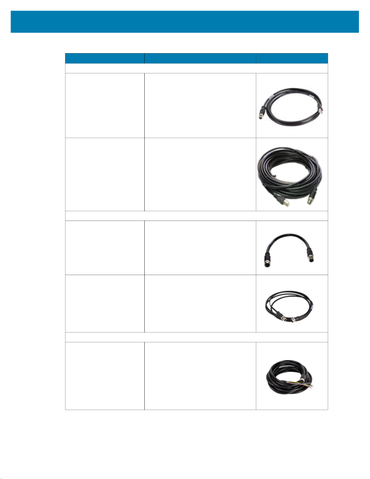
External Light Control Cables
CBL-LGT00000-M1200 5-pin M12 to 5-pin M12 External Light
Control C, 0.3M length
Only compatible with xS40 and xS70
devices that include an external light port.
CBL-LGT00201-M1200 5-pin M12 to 5-pin M12 External Light
Control C, 2M length
Only compatible with xS40 and xS70
devices that include an external light port.
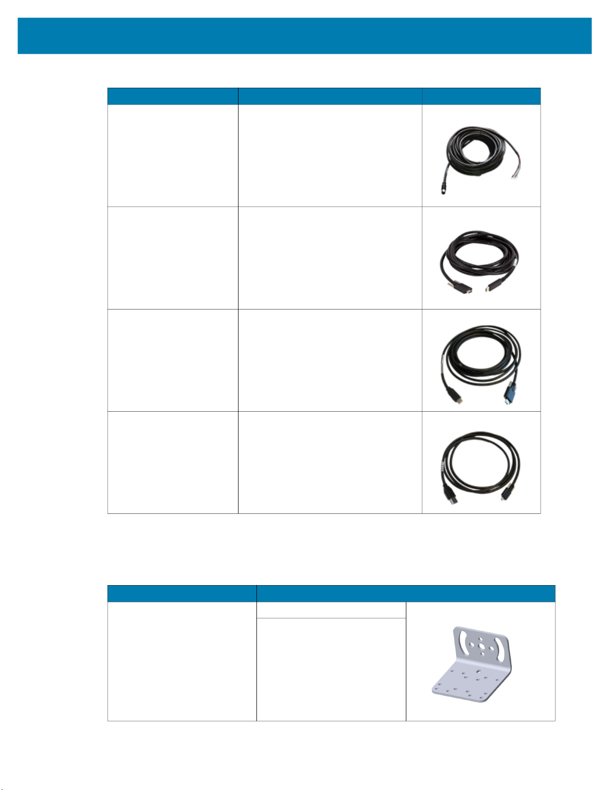
Power Cables
CBL-PWR05001-M1200 12-pin M12 to flying lead breakout cable
Compatible with all FS/VS devices.
14
Getting Started
Table 9 Cables (Continued)
Part Number Description Compatibility
CBL-PWR15001-M1200 12-pin M12 to flying lead breakout cable
Compatible with all FS/VS devices.
CBL-USB00200-USC00 USB-C Cable, 4M length
Compatible with all FS/VS devices.
CBL-USB00400-USC00 USB-A Cable, 2M length
Compatible with all FS/VS devices.
Brackets
CBL-USB00200-USA00 USB-A Cable, 4M length
Compatible with all FS/VS devices.
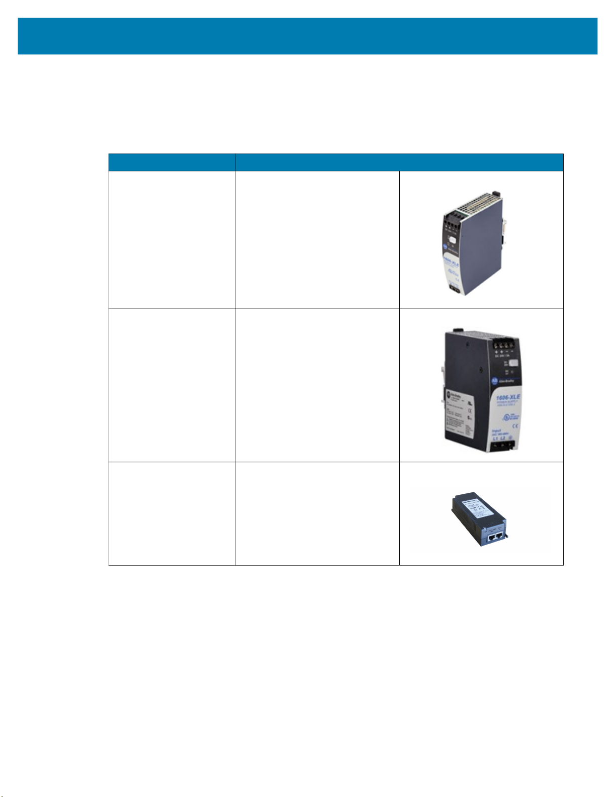
Table 10 L-Mount Bracket
Part Number Description
BRKT-LMNT-U000
L-Mount Bracket
For use with Wide Angle (WA)
xS40 configurations only.
See
Mounting the Device Using
the L-Bracket Accessory
(BRKT-LMNT-U000) on
page 32
for mounting instructions.
15
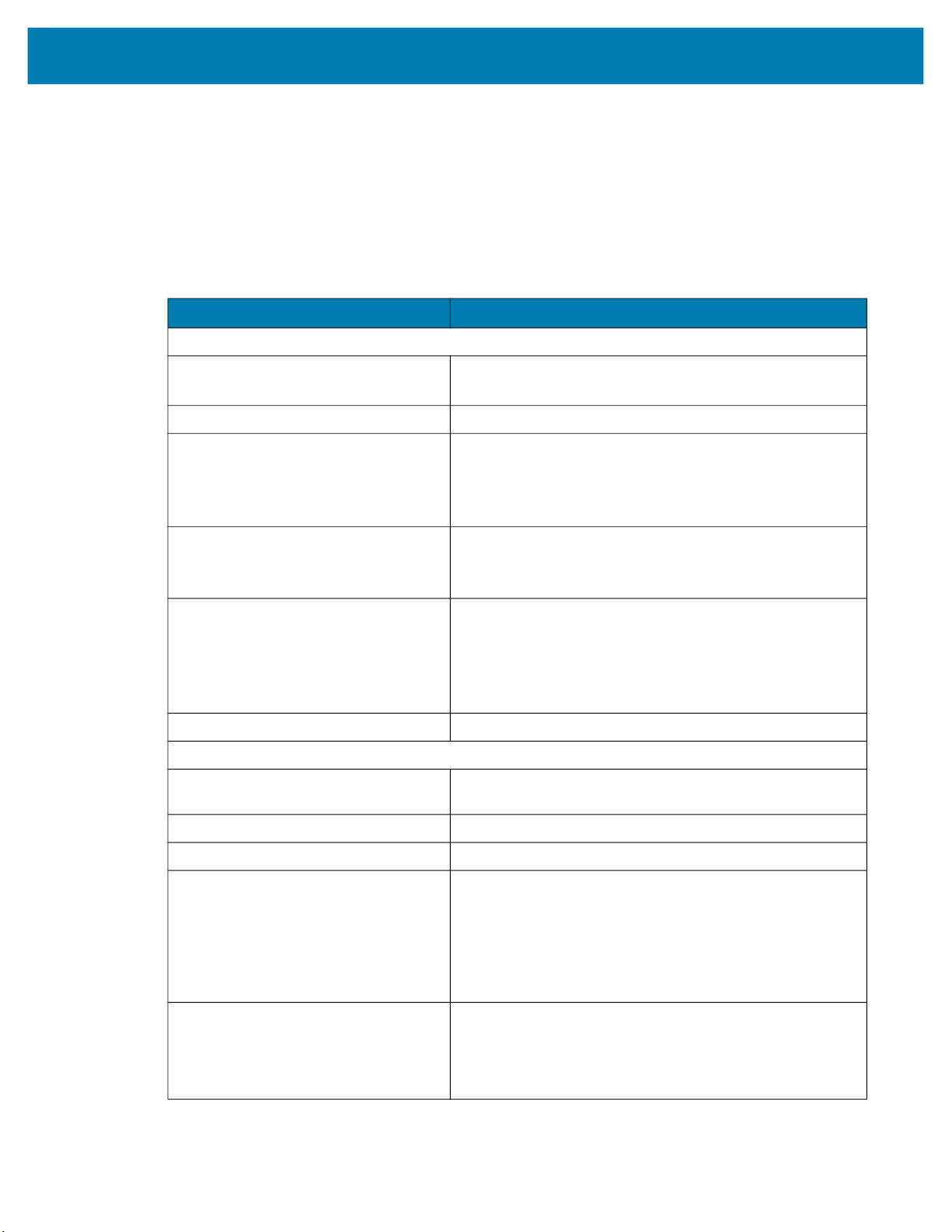
Power Supplies
Table 11 Power Supplies
Part Number Description
PWR-24V03A-0000 Power Supply, 24VDC 3.3AMP, DIN
PWR-24V05A-0000 Power Supply, 24VDC 5AMP, DIN
Getting Started
Rail Mount
Rail Mount
PWR-POE30W-0000 Power over Ethernet Injector, 30W
POE+, AC Input
16
Getting Started
FS/VS Smart Camera Specifications
The tables below describe the design, performance, environment and regulatory characteristics of the
FS/VS Smart Camera series.
xS40 Specifications
Table 12 xS40 Specifications
Item Description
Physical Characteristics
Dimensions 2.1 in. H x 2.5 in. W x 3.6 in. D
54.0 mm H x 64.0 mm W x 91.4 mm D
Weight 14.1 oz./400.0 g
Power 10 to 30 VDC external power supply, 36W max at 24V
• Class 4 PoE+ source, 25.5W max
• Class 3 PoE source, 13W max
• USB Type-C host, 7.5W max at 5V 1.5A or 15W max at 5V 3.0A
Configurable IO (4) Four opto-isolated GPIO: GPIO0,1,2,3
(5) Five non-isolated GPIO: GPIO4,5,6*,7*,8*
*Unavailable when External Light Mode is enabled
Interface Ports (1) M12 X-Coded 1000/100/10 Mbps Ethernet
(1) M12 12-pin Power/GPIO
(1) M12 5-pin External Light Power & Control/GPIO
(1) USB 3.0 SuperSpeed Type-C with DisplayPort
Alt Mode is Available with one or two Ethernet ports
Communication Protocols Ethernet/IP, PROFINET, CC-Link, Modbus TCP, TCP/IP
Performance Characteristics
Image Sensor Monochrome: 2.3 MP (1920 x 1200 pixels) CMOS
Sensor with Global Shutter and 3.0 um Pixel Size
Acquisition Rate Up to 60 frames/second
Aimer Red Class II Laser; 8-point sunburst pattern
Illumination Field replaceable modules:
• (8) 660nm Red LEDs
• (8) 850nm IR LEDs
• (8) 2700K (Color Temperature) White LEDs
• (4) 660nm Red LEDs + (8) 850nm IR LEDs + (8) 2700K (Color
Temperature) White LEDs
Imager Field of View
SR (Standard Range): 10.8mm Liquid Lens
(30° H x 19° V Nominal)
WA (Wide Angle): 6.8mm Liquid Lens
(46° H x 29° V Nominal)
17

Table 12 xS40 Specifications
Item Description
User Environment
Getting Started
Operating Temperature
Storage Temperature -40°F to 113°F / -40° to 70°C
Vibration Resistance EN 60068-2-6, 14 mm @ 2 to 10 Hz, 1.5 mm @ 13 to 55
Shock Resistance EN 60068-2-27, 30g; 11 ms; 3 shocks on each axis
Environmental Sealing IP65 & IP67
Humidity 5% to 90% RH (Non Condensing)
Light Immunity Product must operate in: Incandescent 450 ft candles, Sunlight
Electrostatic Discharge ±15 kV Air, ±8 kV Contact, ±8 kV Indirect
Trigger Durability Withstand 1,000 cycles of operation with no degradation in
Regulatory
Environmental EN 50581:2012
Electrical Safety IEC 62368-1 (Ed.2)
32° F to 113° F/0° C to 45° C (10-30VDC external power supply,
duty cycle-dependent)
32° F to 104° F/0° C to 40° C (POE, duty cycle dependent)
Hz; 2 g @ 70 to 500 Hz; 2 hours on each axis
<6000 ft candles, Florescent 450 ft candles, Mercury Vapor 450
ft candles, Sodium Vapor 450 ft candles, LED 450 ft candles
functionality
EN IEC 63000:2018
EN 62368-1:2014/A11:2017
Laser Safety (xS40 Only) 21CFR1040.10 & 21CFR1040.11
IEC/EN 60825-1:2014 (Ed.3)
LED Safety IEC 62471: 2006 (Ed.1)
EN 62471: 2008
EMI/EMS EN 55032:2015/A11: 2020
EN 55035:2017/A11: 2020
EN 61000-3-2: 2014
EN 61000-3-3: 2013
EN 61000-6-2: 2005,2019
FCC 47 CFR Part 15, Subpart B
ICES-003, Issue 7
EU Declaration of Conformity 2014/30/EU; 2014/35/EU; 2011/65/EU.
Refer to the Declaration of Conformity (DoC) for details of
compliance to the current standards. The DoC is available at:
zebra.com/doc
18

xS70 Specifications
NOTE: The xS70 is only to be used with the metal assembly in order to pass the ESD safe
specification.
Table 13 xS70 Environmental Specifications
Physical Characteristics
Dimensions 2.5 in. H x 2.5 in. W x 3.75 in. D
Weight 22.9 oz./650.0 g
Power 10 to 30 VDC external power supply, 36W max at 24V
Configurable IO (4) Four opto-isolated GPIO: GPIO0,1,2,3
Getting Started
Item Description
63.0 mm H x 64.0 mm W x 95.0 mm D
• Class 4 PoE+ source, 25.5W max
• Class 3 PoE source, 13W max
• USB Type-C host, 7.5W max at 5V 1.5A or 15W max at 5V 3.0A
(5) Five non-isolated GPIO: GPIO4,5,6*,7*,8*
*Unavailable when External Light Mode is enabled
Interface Ports (2) M12 X-Coded 1000/100/10 Mbps Ethernet*
(1) M12 12-pin Power/GPIO/RS-232
(1) M12 5-pin External Light Power & Control/GPIO
(1) USB 3.0 SuperSpeed Type-C with DisplayPort Alt Mode
*Available with one or two Ethernet ports, PoE is only supported
by the primary Ethernet port
Communication Protocols Ethernet/IP, PROFINET, CC-Link, Modbus TCP, TCP/IP
Performance Characteristics
Image Sensor Monochrome: 2.3 MP (1920 x 1200 pixels) CMOS
Sensor with Global Shutter and 3.0 um pixel size
Acquisition Rate 60 frames/second
Illumination Supports many standard external illumination systems while
powered by 24 VDC supply
Imager Field of View Flexible; dependent upon C-mount lens selection
User Environment
Operating Temperature 32° F to 113° F/0° C to 45° C (10-30VDC external power supply,
duty cycle-dependent)
32° F to 104° F/0° C to 40° C (POE, duty cycle-dependent)
Storage Temperature -40° F to 158° F/-40° C to 70° C
Vibration Resistance EN 60068-2-6, 14 mm @ 2 to 10 Hz, 1.5 mm at 13 to 55 Hz; 2 g
at 70 to 500 Hz; 2 hours on each axis
Shock Resistance EN 60068-2-27, 30 g; 11 ms; 3 shocks on each axis
Environmental Sealing IP65 and IP67
Humidity 5% to 90% RH, non-condensing
19
Getting Started
Table 13 xS70 Environmental Specifications (Continued)
Item Description
Light Immunity Product must operate in: Incandescent 450 ft candles, Sunlight
<6000 ft candles, Florescent 450 ft candles, Mercury Vapor 450
ft candles, Sodium Vapor 450 ft candles, LED 450 ft candles
Electrostatic Discharge ±15 kV Air, ±8 kV Contact, ±8 kV Indirect
Trigger Durability Withstand 1,000 cycles of operation with no degradation in
functionality
Regulatory
Environmental EN 50581:2012; EN IEC 63000:2018
Electrical Safety IEC 62368-1 (Ed.2); EN 62368-1:2014/A11:2017
EMI/EMS EN 55032:2015/A11: 2020
EN 55035:2017/A11: 2020
EN 61000-3-2: 2014
EN 61000-3-3: 2013
EN 61000-6-2: 2005,2019
FCC 47 CFR Part 15, Subpart B
ICES-003, Issue 7
EU Declaration of Conformity 2014/30/EU; 2014/35/EU; 2011/65/EU.
Refer to the Declaration of Conformity (DoC) for details of
compliance to the current standards. The DoC is available at:
zebra.com/doc
20

Installation
This section describes the steps to mount the FS/VS Smart Camera with an L-bracket and install an
illumination system into the xS40 or a C-mount lens onto the xS70.
Dimensional Drawings
The dimensional drawings below illustrate the mounting patterns supported by the FS/VS Smart Camera.
For additional information on mounting the device with the L-bracket accessory, see Mounting the Device
Using the L-Bracket Accessory (BRKT-LMNT-U000) on page 32.
xS40 Dimensional Drawings
Figure 1 xS40 Side Dimensions
59.25
2X M3 X 0.50 THD
X DEPTH 4.5 MM MAX
29.00
29.23
25.00
12 PIN M12 CONN
38.70
Optical Axis
2X M3 X 0.50 THD
X DEPTH 4.5 MM MAX
Optical Axis
29.23
19.63
5 PIN M12 CONN
25.00
8 PIN M12 CONN
32.75
USB C CONN
38.70
54.00
59.25
91.40
29.00
21

Figure 2 xS40 Bottom Dimensions
64.00
2X 38.50
2X 19.25
Optical Axis
Installation
78.00
58.50
33.80
4X M3 X 0.50 THD
X DEPTH 4.5 MM MAX
22

xS70 Dimensional Drawings
Figure 3 xS70 Side Dimensions
69.50
49.23
11.35
Installation
3X M3 X 0.50 THD
X DEPTH 4.5 MM MAX
49.23
11.35
Optical Axis
3X M3 X 0.50 THD
X DEPTH 4.5 MM MAX
12.70
8 PIN M12 CONN
39.63
5 PIN M12 CONN
45.00
8 PIN M12 CONN AND
12 PIN M12 CONN
52.75
USB C CONN
58.70
Figure 4 xS70 Bottom Dimensions
64.00
2X 38.50
2X 19.25
29.00
59.25
91.40
Optical Axis
59.25
29.00
58.70
Optical Axis
4X M3 X 0.50 THD
X DEPTH 4.0 MM MAX
17.42
M12 CONN
17.42
M12 CONN
2X 58.50
78.00
2X 33.80
23

Connection Interfaces
xS40 Connections
The xS40 supports connections for USB-C with DisplayPort, power serial and GPIO, x-coded Ethernet and
external lighting. For additional information about the connection interfaces, see Cable Pin Outs on
page 29.
Figure 5 xS40 Connection Interfaces
Installation
1
2
3
4
1 External Lighting
2 X-Coded Ethernet Port
3 USB-C (with DisplayPort)
4 Power Serial and GPIO
24

xS70 Connections
The xS70 supports connections for USB C with DisplayPort, power serial and GPIO, x-coded Ethernet,
and external lighting. For additional information about the connection interfaces, see Cable Pin Outs on
page 29.
Figure 6 xS70 Connection Interfaces
Installation
1
2
3
4
5
1 X-Coded Ethernet Port (Secondary)
2 External Lighting
3 X-Coded Ethernet Port
4 USB C (with DisplayPort)
5 Power Serial and GPIO
25

Torque Specification
To guarantee an IP65 & IP67 product specification, Zebra cables and/or connector covers must be torqued
to the following specification:
• Torque for M12 Zebra cables: 24.0 in-lbs
• Torque for connector covers: 10.0 in-lbs
Installation
NOTE:
covers must be torqued at installation to guarantee an IP65 and IP67 specification if cables are not
used.
To ensure proper connector cover seating, see Figure 7 for the reference dimension (in mm) of the 12 pin
M12.
Figure 7 12 Pin M12 Reference Dimension
Connector covers are hand tightened from the factory to allow for easy hand removal. The
5.80 mm
For additional information on Zebra cables, see Communication Cables on page 13.
26

Power Sources
The xS40 and xS70 devices can be powered through the 12-pin M12 connector, Power over Ethernet
(PoE), or USB Type C for maximum flexibility. A power priority scheme selects power from the M12
connector over PoE, and PoE over USB-C to ensure the least restrictive power source is utilized. Changes
to the power source trigger a reboot.
Since power from any source is finite, a budget is automatically derived by the vision system and
dynamically allocated to prevent an overload condition. Allocation is based on sensor type and enabled
features such as Ethernet PHY’s, digital outputs, and advertised USB Type C port current. Models with
internal illumination reduce illumination intensity or duration to operate within budget, and may disable
internal illumination entirely if necessary.
NOTE: It is recommended to develop jobs with power sources and auxiliary equipment in the final
intended configuration to prevent mismatch at deployment.
12 Pin M12 Power Input
If the input voltage is above 21.5 V, the vision system enables up to 1.5 A output to the USB Type C
connector and allows for simultaneous operation of internal and external illumination. If the external light
connector is placed in external light mode, power is shunted from the power supply directly to the light
through a bypass circuit able to support the high peak currents of strobe lights. A self-resettable fuse
prevents physical overload of the 12 pin M12 connector.
Installation
If less than 21.5 V is provided to the device, the advertised USB Type C current is lowered to 500 mA and
overall power budget is reduced. This may impact allowable internal illumination configurations. As a
result, a 24 V industrial power supply capable of high pulse currents of long duration is recommended for
best performance.
Power Over Ethernet
The xS40 and xS70 devices support operation from power sourcing equipment meeting the 802.3at class
4 (30 W) or 802.3af class 3 (15.4 W) IEEE Power Over Ethernet (PoE) standards. These are commonly
referred to as PoE+ and PoE respectively by equipment providers.
Peak power draw must be strictly maintained within the power envelope of the power sourcing equipment.
If the external light connector is enabled in external light mode, the vision system generates 24 V to power
the external light with the following limitations in place:
• Simultaneous activation of the internal and external illumination is not permitted.
• Auto-strobe lights with high pulse current are not supported and trip over current protection in the vision
system, disabling the external light connector.
• External lights with adjustable intensity may be used, provided the peak current draw is below the over
current protection limit. It is recommended to start with the lowest intensity setting and work upwards, or
to use the auto-tune feature.
Power over Ethernet requires an extra regulation step which incurs additional thermal buildup within the
device. As a result, the specified operating temperature range is reduced when powered by PoE.
USB Type C
USB Type C allows for novel and cost-effective installations provided the following constraints are
acceptable:
• Digital GPIO are unavailable
27

Installation
• Optocoupled GPIO is still functional provided the COMMON_IN and COMMON_OUT are properly
terminated.
• The External Light Connector is disabled and cannot be used in GPIO or External Light modes.
• 0 V to 10 V analog output is disabled.
• Internal illumination is limited or requires a USB power source with further capabilities to be enabled at
any capacity.
CAUTION: The xS40 and xS70 devices boot from legacy USB host ports, however, current draw is
not guaranteed to be under 500 mA and device functionality may be restricted to the extent that
performance can be impaired. An override mode can be enabled for legacy host ports that are known
by the operator to be capable of supplying up to 1.5 A. Ports of this type are often described as having
USB BC1.2 or USB charging support.
Grounding for Electro-Magnetic Compliance and ESD Safe
The vision system is designed with a rugged metal chassis connected internally to ground for robust
Electro-Magnetic Compliance (EMC) and ESD Safe operation. Do not mount to any conductive object,
body, structure, or mechanism that may become connected to line voltage or a voltage potential other than
Protected Earth Ground. Chassis grounding via cable shield, mounting screws, or low inductance ground
strap to a local Protected Earth Ground is acceptable.
NOTE: There is no galvanic connection to Earth Ground when the device is powered over an
unshielded Ethernet cable. In this scenario, grounding to local Earth Ground through another cable
shield, mounting screw, or ground strap is required for ESD Safe compliance and best practice for
EMC.
28

Cable Pin Outs
This section provides pin and cable color information for the power and I/O, Ethernet, and external lighting
connectors.
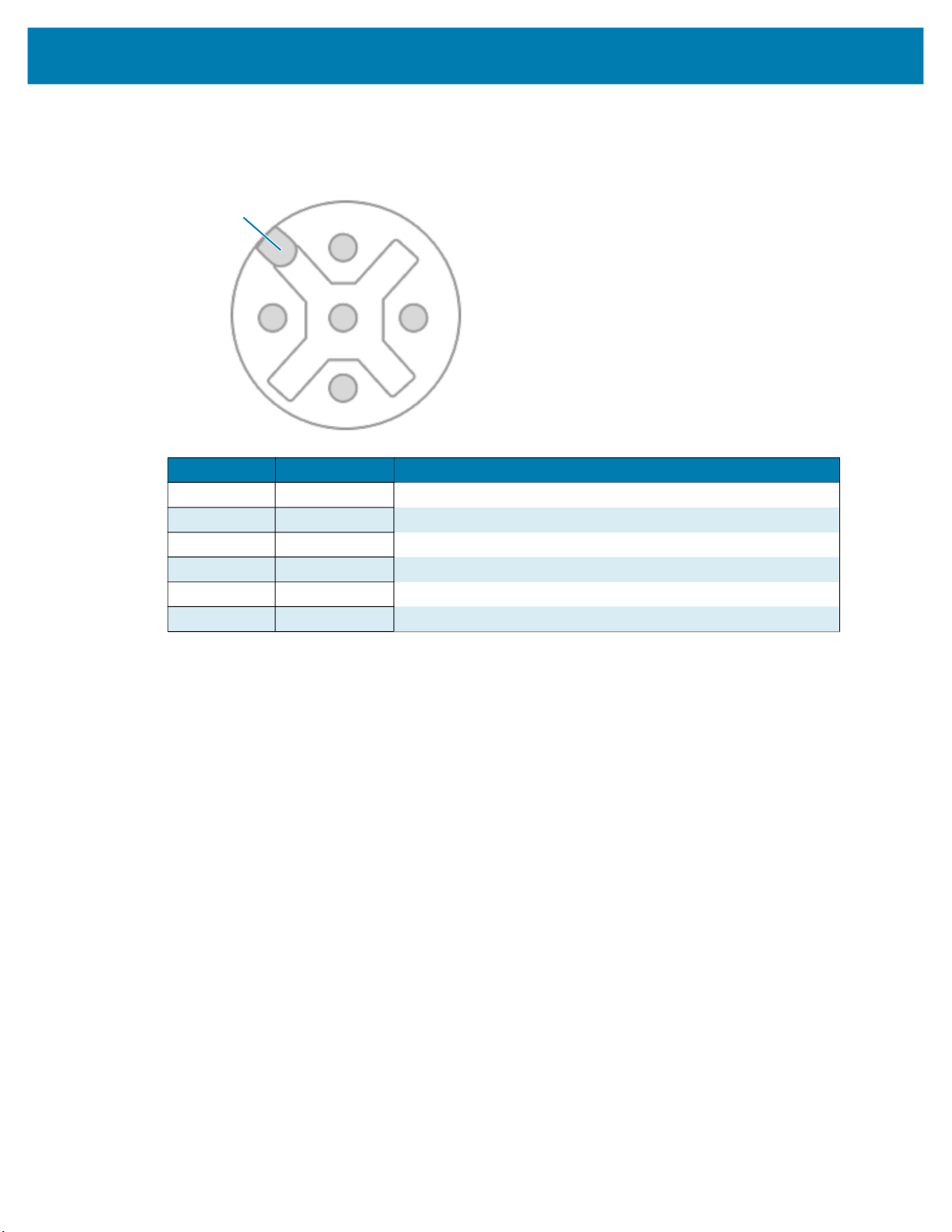
Power and I/O Connector
Figure 8 Power and I/O Connector - 12 Pin Diagram
Installation
Key Position
3
4
11
5
6
2
10
12
7
1
9
8
Pin Color Description
1 Yellow GPIO2
2 White / Yellow TXD
3 Brown RXD
4 White / Brown GPIO4
5 Violet GPIO5
6 White / Violet COMMON_IN
7 Red DC_IN
8 Black GND
9 Green COMMON_OUT
10 Orange GPIO0
11 Blue GPIO1
12 Grey GPIO3
SHELL Bare SHIELD
29

Ethernet Connector
Figure 9 Ethernet Connector - 8 Pin Diagram
Key Position
Installation
2
3
1
8
7
4
5
6
Pin Description
1 TP1+
2 TP1-
3 TP2+
4 TP2-
5 TP4+
6 TP4-
7 TP3-
8 TP3+
SHELL SHIELD
30
External Light Connector
Figure 10 External Light Connector - 5 Pin Diagram
Key Position
Installation
4
1
2
Pin Color Description
1 Brown DC_OUT / GPIO8
2 White GPIO7
3 Blue GND
4 Black GPIO6
5 Gray ANALOG_OUT
SHELL Bare SHIELD
3
31
Installation
Setting up an FS/VS Smart Camera
The sections below describe the steps to mount the xS40 or xS70 to the L-bracket accessory using Figure
11 and Figure 12 to understand its hole positions.
General Mounting Instructions
1. Align the holes on the mounting surface with the mounting holes on the device.
2. Insert screws into the mounting holes and tighten. It is recommended to use four M3 screws to attach
the camera on the bottom surface using a tightening Torque of 6.0 in-lbs.
3. See Dimensional Drawings on page 21 for mounting hole placements on the devices to determine the
proper screw lengths needed based on the provided tapping depths into the camera.
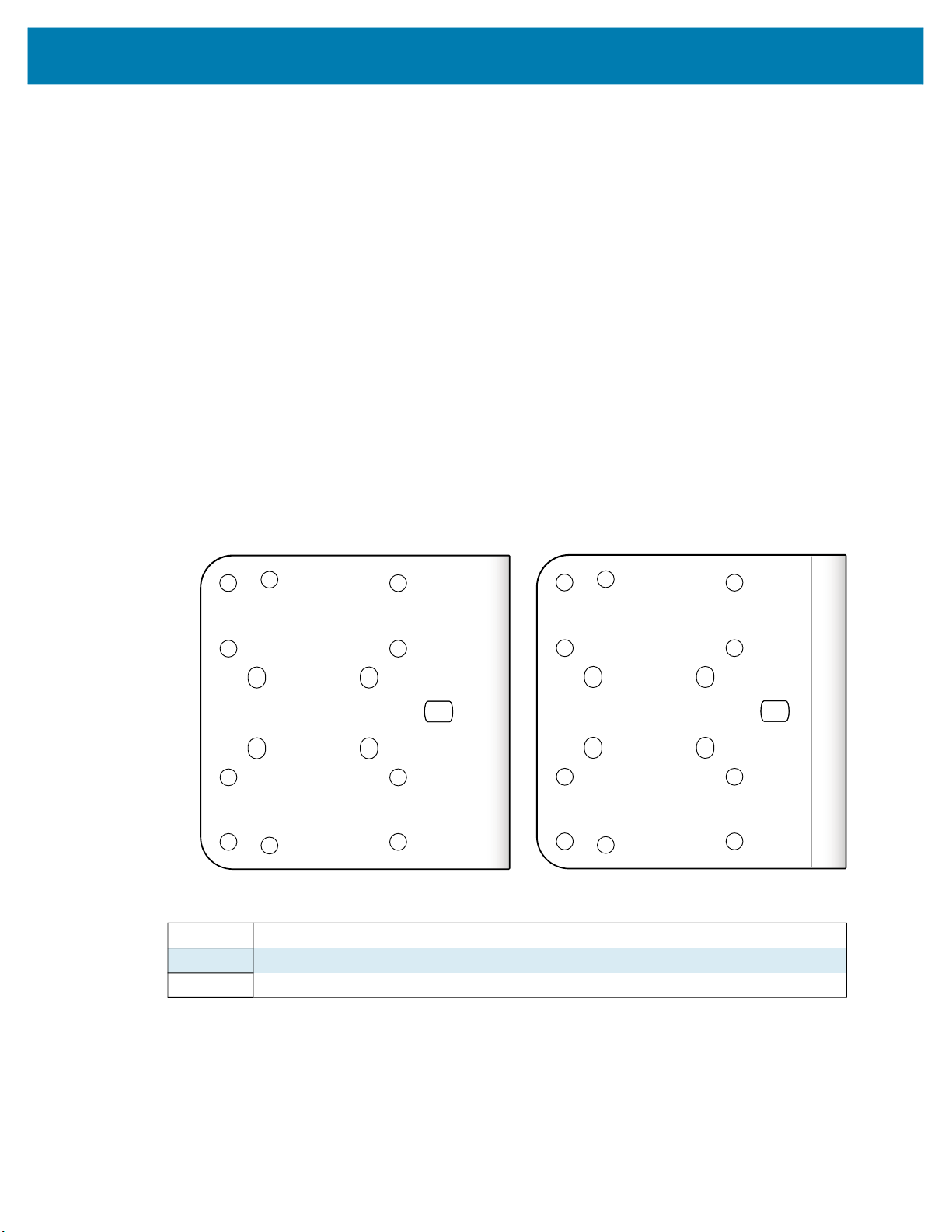
Mounting the Device Using the L-Bracket Accessory (BRKT-LMNT-U000)
1. Use the mounting screws provided with the kit to attach the camera to the bracket. The recommended
Toque is 6.0 in-lbs.
2. Refer to the L-bracket mounting options outlined below.
Figure 11 Bottom and Side Mounting Hole Patterns
6
1
3
Bottom Surface Mounting Options
2
4
5
7
8
1-4 Bottom Surface Mounting Holes for the xS40 and xS70
5-8 Side Mounting Holes for the xS40
5-9 Side Mounting Holes for the xS70
9
Side Mounting Options
32

Installation
Figure 12 Mounting to the Structure Hole Pattern
3
2
5
1
4
1-2 M5 Clearance
3-4 1/4-20 Clearance
5 M8 Clearance
6 M8 Clearance Slots
6
Figure 13 Side Mounting Option
33

Figure 14 Bottom Mounting Option
Installation
34

Installation
Illumination System Installation (xS40 Only)
To install the illumination system on the xS40, follow the steps below:
1. Place the gasket onto the camera.
2. Attach the Illumination PCB to the camera via the board to board connector and secure it with two
screws. The recommended Torque is 6.0 in-lbs using the Torx T8 fasteners.
3. Place the filter onto the camera exit window, lining up the corner chamfer of the filter to the corner
chamfer of the camera housing (if required).
4. Place the illumination plate assembly onto the camera.
5. Attach the top cover and secure with four screws. The recommended Torque is 6.0 in-lbs using the
Torx T8 fasteners.
Illumination System Disassembly (xS40 Only)
To disassemble the illumination system on the xS40, follow the steps below:
1. Remove the four screws and remove the top cover.
2. Remove the illumination plate assembly.
3. Remove the filter (if applicable).
4. Remove the two screws and gently lift the PCB to disconnect it from the camera.
The gasket can be left in place unless damaged. Replace the gasket if it is damaged to maintain its IP67
specification.
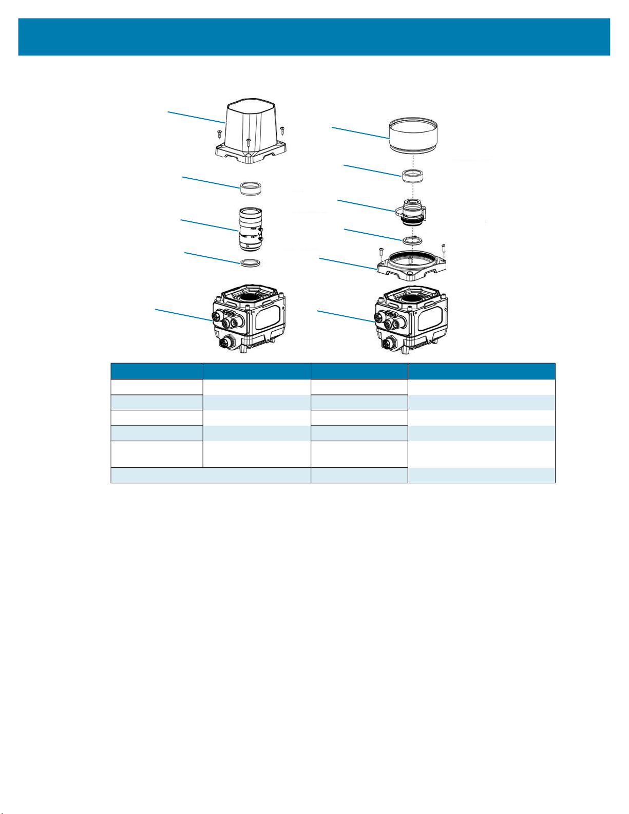
Figure 15 Illumination System Installation
1
2
3
4
5
6
35

Installation
1 ESD Safe Cover (Four Screws)
2 Illumination Plate Sub-Assembly
3 Filter Assembly
4 Illumination PCB (Two Screws)
5 Illumination Plate Gasket
6 Main Assembly
Threaded Lens Cover Assembly Installation
If a threaded lens cover assembly is preferable over the IP67 cover provided with the xS70, follow the
instructions below for installation.
NOTE: The threaded lens cover assembly can only be used with C-Mount lenses.
1. Remove the lens cover.
2. Place threaded lens adapter accessory onto reader (HN-001466-01).
3. Insert and tighten the screws. The recommended torque is 6.0 in-lbs using the Torx T8 fasteners.
4. Install filter into reader (if required).
5. Thread the lens into the reader.
6. Place the reader at the desired working distance from the focal point.
7. Adjust lens (if necessary).
8. Thread on appropriate length cover to accommodate chosen lens.
C-Mount Lens Installation (xS70 Only)
To install the c-mount lens onto the xS70, follow the steps below:
1. Remove the lens cover.
2. Install the filter into the reader (if required).
3. Thread the lens into the reader.
4. Place the reader at the desired working distance from the focal point.
5. Adjust the lens (if necessary).
6. Attach the front cover.
7. Insert and tighten the screws. The recommended Torque is 6.0 in-lbs using the Torx T8 fasteners.
36
Installation
Figure 16 Optional Accessory Assembly Drawings
1
1
2
2
3
3
4
5
4
5
6
Number Description Number Description
1
2 Polarizer 2 Polarizer
3
4 Filter 4 Filter
5 Assembly 5 Threaded Lens Cover Bracket
Lens Cover
C-Mount Lens
1
3
6 Assembly
Threaded Lens Cover
C-Mount Lens
(HN-001466-01)
37

Setting Focus
To focus the device upon first use, calibrate the gain and exposure settings by utilizing the Live View
feature in the Web HMI of the Zebra Aurora application. Users can also manually adjust the focus and the
aperture of the C-mount lenses. For additional information on using the Web HMI, see Accessing the Web
Human-Machine Interface (HMI) on page 64.
NOTE: The set screws must be loosened before adjusting the lens. The set screws are fixed after the
optimum focus and aperture are set.
Installation
38

Using the Smart Camera
This section describes using the FS/VS Smart Camera and optimizing the device’s utility for its use
case by leveraging its connection interfaces.
USB Type C
The xS40 and xS70 devices implement a full capability 5 Gbps USB 3.0 USB Type C port with support
for DisplayPort Alt Mode. The sealed port implements a standard USB Type C dual screw lock
mechanism for secure connections. When paired with the IP67 series of Zebra screw locking cables,
the interface maintains a full IP67 seal.
CAUTION: The sealing gasket on IP67 series Zebra USB Type C cables require adequate
pressure for proper seal and connector engagement. Always tighten the locking screws when
using these cables, even if IP67 sealing is not required.
When connected as a peripheral to a USB host, the xS40 and xS70 devices can be configured to
support the following functionality:
• RNDIS Ethernet over USB
• HID keyboard
When operating as a host, the USB Type C port supports many types of accessories and functionality,
including:
• Native USB-C displays
• USB-C to Display Port and USB-C to HDMI adaptors
• HID compliant mice, keyboards, and trackpads
• USB mass storage devices for firmware updates
• USB docks and hubs
NOTE: DisplayPort output is only supported over USB Type C to Type C cables capable of
SuperSpeed data rates. High speed cables, often described as charging cables, do not have
the necessary data wires for DisplayPort functionality.
Supported Display Resolutions
Display resolution is automatically negotiated upon connection. Displays with at least 1920 x 1080
resolution provide the best user experience.
The FS/VS Smart Camera series supports the following resolutions:
• 1024 x 768
39

• 1280 x 800
• 1280 x 1024
• 1366 x 768
• 1600 x 900
• 1600 x 1050
• 1920 x 1080
• 1920 x 1200
NOTE: Monitors with USB-C input offer an efficient method for quick and easy configuration over a
single USB Type C to Type C cable. An attached xS40 or xS70 device powers directly from the
monitor’s USB Power Delivery and output the Human Machine Interface (HMI) directly to the display.
A USB mouse and keyboard attached to the monitor hub ports provide the user with interface control.
Battery powered portable USB Type C monitors are also compatible for easy status or manipulation in
the field.
User Interface
The FS/VS Smart Camera provides various forms of feedback in the form of decode LEDs, beeper
indications, label LEDs, and UIF codes that keep the user aware of specific device states.
Decode LEDs
The xS40 and xS70 have 360° LED decode indicators that flash green upon successful decode and red
upon job failure. For information on configuring the 360° LEDs, see General Settings on page 59.
Figure 17 xS40 and xS70 360° Decode LED
xS40
xS70
40

User Interface Label
The xS40 and xS70 devices provide the user with LED indicators and switches to indicate
the device state and optimize focus. Table 14 below lists all LED indications for the FS/VS Smart Camera
series. The xS40 and xS70 have trigger and tune buttons that are controlled by two switches on the sensor
PCB. The TRIG switch acts a trigger, and the TUNE switch allows the user to adjust and optimize focus.
For additional information on trigger configuration, see Configuration of Trigger Modes on page 60.
Figure 18 FS/VS Smart Camera Series UI Labels
1
2
6
xS40 xS70
4
3
5
7
1
7
3
2
4
5
6
8
Number xS40 Indicator Number xS70 Indicator
1 Power 1 Power
2 Power over Ethernet (PoE) 2 Ethernet
3 Online 3 Power over Ethernet (PoE)
4 Focus 4 Online
5 Warning 5 Focus
6 Trigger 6 Warning
7 Tuning 7 Trigger
8 Tuning
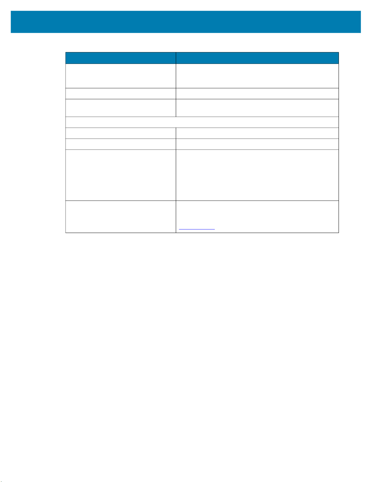
For additional information on using the TRIG button to perform a factory reset on the device, see Factory
Reset the Device on page 75
41

LED and Beeper Indicators
The table below describes the LED and beeper indications of the FS/VS Smart Camera upon device
events such as power up, running a job, maintenance operations, and parameter programming.
Table 14 LED Indicators
Device
Event Beeper 360° LEDs Power
Power Up
Bootup - Uboot
(Bootloader)
Bootup - Linux,
Low power
(Developer
Mode)
Bootup - Linux,
Full Power
Device States
Ready (Job
Loaded /Active)
Running (Job
Triggered)
Stop High, Low Off - Off Off Off No Activated
Setup None Off - Off Off Off Job editing in
Error (Job Error) Low, Low Off - Solid
Maintenance Operations
Firmware
Update Start
Firmware
Update Success
Firmware
Update Fail
None Off Solid
Low,
Medium,
High
Low,
Medium,
High
Low, High Off - Green
As
Configured
- Red Blinking - Red
- - - - - - Firmware
Low, Low Solid Red - Solid
Green
(Single
Blink)
Green
(Single
Blink)
As
Configured
Red
Green
(Slow
Blink)
Solid
Green
- Solid
Status
Off Off Off Hardware
Off Off Off Linux booted,
Off Off Off Linux booted,
Blinking
Green
Red
Blinking
Red
Focus
Status
Off Off Job is waiting on
As
Configured
Off Solid Red Job has failed to
Off Off Firmware
Off Off Firmware
Error
Status
As
Configured
Description
Controlled
Core Services
not running yet,
Low Power
Condition
applies to low
USB or PoE
Power.
Core Services
not running yet
Trigger (Core
Services in
Standby state)
Job is currently
running (Core
Services in Run
state)
Jobs (Core
Services in
Stopped state)
progress (Core
Services in App
Connected
state)
complete
properly
Update in
progress
Update
completed
successfully. No
success
indication, boot
normally.
Update has
failed
42

Table 14 LED Indicators (Continued)
Device
Event Beeper 360° LEDs Power
Reset to
Defaults
(Hold Trigger on
Powerup)
AutoTune Start Medium Off - - Green
AutoTune
Success
AutoTune Fail Low, Low Off - - Solid Red Off AutoTune has
Parameter Programming
Parameter Entry
Accepted
Parameter
Number Entry
Parameter Entry
Error
Long
Medium
(on
success by
Config
Manager)
High, High Off - - Solid
High, Low,
High, Low
High, Low Green
Low, High Red (Single
Red (20s),
Yellow
(10s),
Normal
bootup
Green
(Single
Blink)
(Single
Blink)
Blink)
- Red 1s,
- Green
- Green
- Red
Status
Green
1s
alternati
ng,
Normal
bootup
(Single
Blink)
(Single
Blink)
(Single
Blink)
Focus
Status
Off Off To Reset
Blinking
Green
Off Off Successful
Off Off Number
Off Off Input error:
Error
Status
Off AutoTune in
Off AutoTune
Description
Defaults, hold
trigger during
Powerup and
release when
360 LED is
yellow. (Not
Factory defaults.
Do not lose
licenses or
Jobs).
progress
completed
successfully
failed
program exit with
change in
parameter
setting.
expected. Enter
value using
numeric bar
codes.
incorrect bar
code,
programming
sequence, or
Cancel scanned.
43

User Interface Framework Codes
The table below describes specific system events and the feedback that the interface provides to convey
certain device states to the user.
Table 15 UI Codes
UIF Name System Event Beeper LED
LINUX_BOOTUP_LOW_POWER Not used One medium
LINUX_BOOTUP_FULL_POWER Not used One medium
JOB_READY Not used One medium
volume, low tone,
short duration beep.
One medium
volume, medium
tone, short duration
beep
One medium
volume, high tone,
short duration beep
volume, low tone,
short duration beep.
One medium
volume, medium
tone, short duration
beep.
One medium
volume, high tone,
short duration beep.
volume, low tone,
short duration beep.
One medium
volume, high tone,
short duration beep.
The decode LED flashes
green for 250 ms once.
The power LED
continuously flashes green
at 1 Hz with 50% duty cycle
The run mode, focus, and
warning LEDs are off.
The decode LED flashes
green for 250 ms once.
The power LED stays ON in
green.
The run mode, focus and
warning LEDs are off.
The run mode LED
continuously flashes in
green at 2 Hz with 50% duty
cycle.
The power LED responds
as configured.
JOB_RUNNING Not used No beeper
feedback.
JOB_STOP Not used One medium
volume, high tone,
short duration beep.
One medium
volume, low tone,
short duration beep.
JOB_SETUP Not used No beeper
feedback.
The decode, focus and
warning LEDs are off.
The run mode LED stays on
in green.
The power, decode, focus,
and warning LEDs respond
as configured.
The power LED responds
as configured
The decode, run mode,
focus, and warning LEDs
are off.
The power LED responds
as configured.
The decode, run mode,
focus, and warning LEDs
are off.
44

Table 15 (Continued)UI Codes
UIF Name System Event Beeper LED
JOB_ERROR The device becomes
underpowered.
FIRMWARE_UPDATE_START Firmware update
Starts.
FIRMWARE_UPDATE_END Firmware update ends. The beeper is off. The power LED responds
Two medium
volume, low tone,
short duration
beeps.
No beeper
feedback.
The run mode LED stays on
in red.
The warning LED stays on
in red.
The power LED responds
as configured.
The decode and focus
LEDs are off.
The decode LED
continuously flashes red at
2 Hz with 50% duty cycle.
The run mode LED
continuously flashes red at
2 Hz with 50% duty cycle
The power LED responds
as configured.
The focus and warning
LEDs are off.
as configured.
FIRMWARE_UPDATE_FAIL Firmware update
failure.
AUTOTUNE_START Autotune job starts One medium
One medium
volume, low tone,
long duration beep.
volume, medium
tone, short duration
beep.
The decode, run mode,
focus, and warning LEDs
are off.
The decode LED
continuously flashes in red
at 5 Hz with 50% duty cycle
The run mode LED
continuously flashes in red
at 5 Hz with 50% duty cycle.
The power LED responds
as configured.
The focus and warning
LEDs are off.
The focus LED
continuously flashes in
green at 2Hz with 50% duty
cycle.
The power LED responds
as configured.
The run mode LED
responds as configured.
The decode and warning
LEDs are off.
45

Table 15 (Continued)UI Codes
UIF Name System Event Beeper LED
AUTOTUNE_SUCCESS Autotune job
completes
AUTOTUNE_FAIL Autotune job failure. One low volume,
BARCODE_DECODE_START PreDecodeProcedure
(asynchronous)
One high volume,
high tone, short
duration beep.
low tone, short
duration beep.
The beeper is off. The run mode LED stays on
The focus LED stays on in
green.
The power LED responds
as configured.
The run mode LED
responds as configured.
The decode and warning
LEDs are off.
The focus LED stays on in
red.
The power LED responds
as configured.
The run mode LED
responds as configured.
The decode and warning
LEDs are off.
in amber
The decode LED is off.
BARCODE_DECODE_SUCCESS PostDecodeProcedure
when beep_on_decode
is false.
BARCODE_DECODE_FAILURE PostDecodeProcedure
when a decode fails.
FACTORY_RESET Factory Reset starts Two medium
One high volume,
medium tone, short
duration beep by
default.
No beeper
feedback.
volume, medium
tone, short duration
beeps.
The power, focus and
warning LEDs respond as
configured.
The run mode LED is off.
The decode LED flashes in
green for 50 ms once by
default.
The power, focus and
warning LEDs respond as
configured.
The run mode LED is off.
The decode LED flashes
red for 50 ms once by
default.
The power, focus, and
warning LEDs respond as
configured.
The decode LED
continuously flashes in red
at 5Hz with 50% duty cycle.
The power, run mode,
focus, and warning LEDs
respond as configured.
46
Data Capture
This section describes aiming patterns and decode ranges for the xS40 as well as minimum focus
distances for the xS70 while using a C-mount lens.
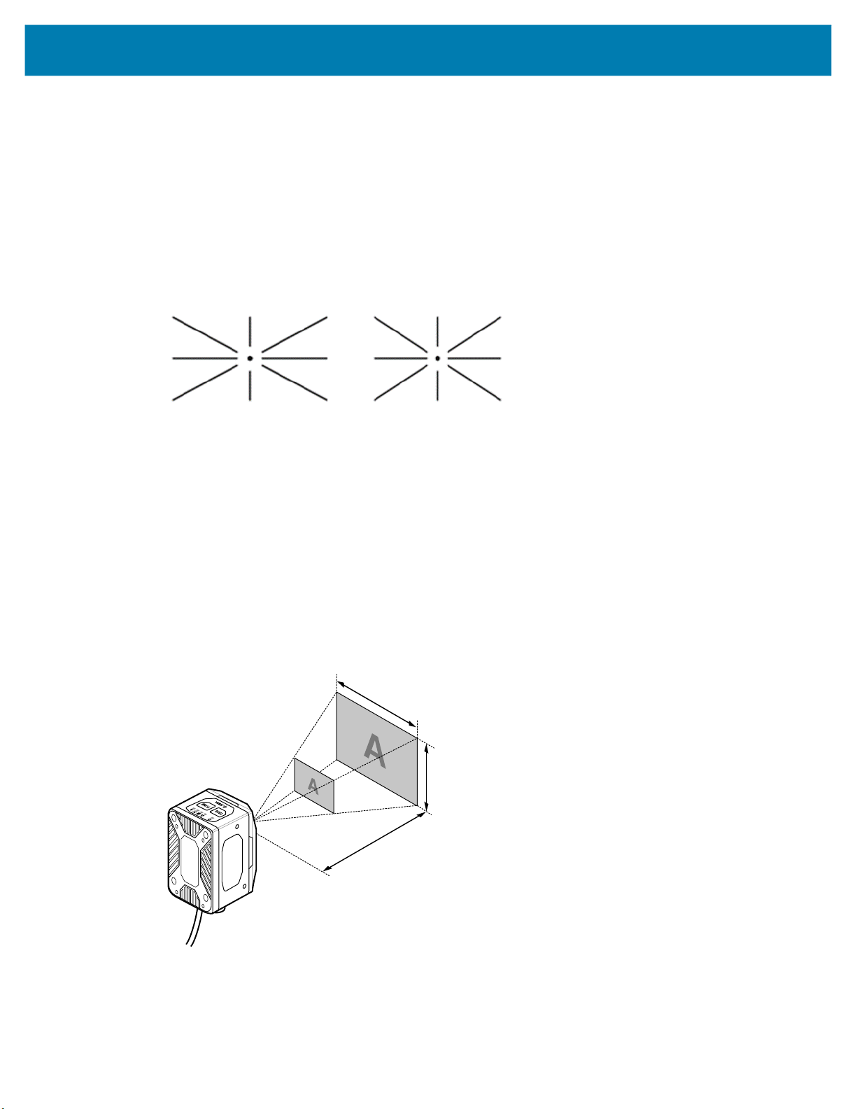
Aiming Patterns
The xS40 has a red Class II laser aimer that generates the pattern shown below in Figure 19. The aimer
indicates the center and size of the field of view including diagonal corners 24 in. away from the subject.
Figure 19 xS40 Laser Aiming Pattern
xS40
(46° FoV)
xS40 Decode Ranges
The xS40 features a 30° and 46° field of view lens that meets the decode ranges specified in Table 16 at
room temperature under ambient conditions.
The device has two imaging FoVs:
• 30 (H) x 19 (V)
• 46 (H) X 29 (V)
Figure 20 xS40 Imaging Fields of View
xS40
(30° FoV)
47

Table 16 xS40 Decode Ranges
Symbology
Typical Near Typical Far Typical Near Typical Far
5 mil Code 128 8 cm (3 in.) 61 cm (24 in.) 8 cm (3 in.) 36 cm (14 in.)
10 mil Code 128 8 cm (3 in.) 124 cm (49 in.) 8 cm (3 in.) 76 cm (30 in.)
15 mil Code 128 8 cm (3 in.) 178 cm (70 in.) 8 cm (3 in.) 107 cm (42 in.)
20 mil Code 128 8 cm (3 in.) 234 cm (92 in.)* 8 cm (3 in.) 142 cm (56 in.)*
5 mil Data Matrix 8 cm (3 in.) 33 cm (13 in.) 8 cm (3 in.) 20 cm (8 in.)
10 mil Data Matrix 8 cm (3 in.) 71 cm (28 in.) 8 cm (3 in.) 46 cm (18 in.)
15 mil Data Matrix 8 cm (3 in.) 102 cm (40 in.) 8 cm (3 in.) 69 cm (27 in)
30 mil Data Matrix 8 cm (3 in.) 198 cm (78 in.)* 8 cm (3 in.) 132 cm (52 in.)*
NOTE: Near distance is limited by barcode width and will focus no closer than 3 in.
*May be limited by illumination output from the power source, wavelength, or polarizer accessory (non-IR). The
above ranges are also applicable to 24 VDC powered unpolarized red illumination without ambient light.
xS70 Minimum Focus Distances
The table below outlines the minimum focus distances for C-mount lenses, provided by Zebra for use with
the xS70 device. Decode ranges are dependent upon the selected lens effective focal length, focusing
distance setting, and lens aperture setting.
FS40-SR 30° Mono FS40-WA 46° Mono
Table 17 Minimum Focus Distances
C-Mount Moritex Lens 8 MM 12 MM 16 MM 25 MM 35 MM
Minimum Focus Distance
from the Lens
6.35 cm
(2.5 in.)
11.43 cm
(4.5 in.)
General Purpose Input and Outputs
The xS40 and xS70 devices have two types of general-purpose inputs and outputs (GPIO). GPIO0
through GPIO3 are optically coupled to provide electrical isolation and wiring flexibility. GPIO4 through
GPIO8 are 24 V Digital GPIO, which are not isolated and source power from the external power supply or
Power over Ethernet (PoE). Digital GPIO is unavailable when the system is powered by USB, however,
optocoupled GPIOs remain functional when COMMON_IN and COMMON_OUT are terminated
appropriately.
Optically Coupled GPIO
Optocoupled GPIO have the advantage of being electrically isolated from the rest of the vision system and
require external reference through the COMMON_IN and COMMON_OUT wires. The termination of
COMMON_IN and COMMON_OUT to an external voltage or ground determines if the input or output is
Sinking (also known as NPN) type or Sourcing (also known as PNP) type.
In output mode, these GPIO perform similarly to switches connecting the GPIO pin to COMMON_OUT.
When disabled, the GPIO pin is disconnected from COMMON_OUT and allowed to float. As a result,
optocoupled outputs turn on relatively quickly, while the turn off time is dependent upon how quickly the
connected load dissipates charge.
10.16 cm
(4 in.)
11.43 cm
(4.5 in.)
19.05 cm
(7.5 in.)
48
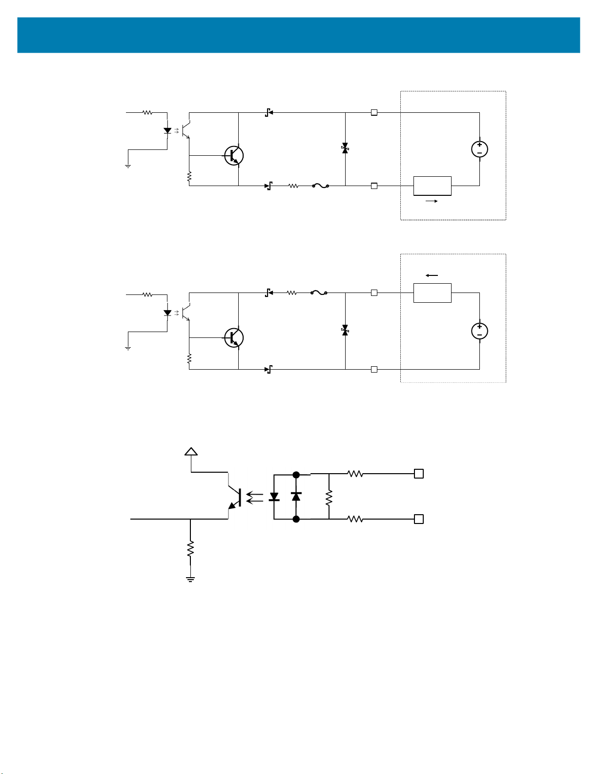
Figure 21 Output Mode Equivalent Circuit Diagram for NPN and PNP Mode
ConnectedEquipment
COMMON_OUT
GPI Opin
PNPSourc ing
OutputMode
CPU
10Vto30VDC
LOAD
I
LOAD
ConnectedEquipment
COMMON_OUT
CPU
10Vto30VDC
LOAD
GPIO pin
NPNSinking
OutputMode
I
LOAD
3.3V
COMMON_IN
GPIOpin
Inputmode
CPU
Optocoupled inputs are enabled when voltage is applied across the GPIO pin and COMMON_IN.
Figure 22 Input Mode Equivalent Circuit Diagram for NPN and PNP Mode
Optocoupled GPIO can be operated in a non-isolated fashion by terminating COMMON_IN and
COMMON_OUT to the DC_IN or GND wires used to power the device.
49

The following table provides a useful reference for such connections.
Table 18 Connection References
Wire Termination Configuration
COMMON_IN GND Sinking Input (NPN)
COMMON_IN DC_IN Sourcing Input (PNP)
COMMON_OUT GND Sinking Output (NPN)
COMMON_OUT DC_IN Sourcing Output (PNP)
While it is possible to configure inputs and outputs of the same type, this is not recommended as inputs
and outputs must be of opposite type to be compatible. All optocoupled GPIO share the COMMON_IN for
input mode and COMMON_OUT for output mode. Therefore, all inputs must be of the same type and all
outputs must be of the same type. For example, it is not possible to simultaneously configure sinking
output on GPIO0 and sourcing output on GPIO1.
In practice, sinking inputs paired with sourcing outputs is very common. This combination is compatible
with widely available digital industrial GPIO, which typically only support sinking type inputs.
NOTE: Refer to the documentation of the connected auxiliary equipment to ensure a compatible
configuration, and remember to leave unused GPIO in a disabled state.
Optocoupled outputs are individually fused to protect against damage from short circuit or overload events.
Since no power is consumed from the vision system, optocoupled GPIO are always available regardless of
power source and have no impact on power budgeting.
Digital Industrial GPIO
Unlike optocoupled GPIO, digital GPIO actively drive the output signal high and low for significantly faster
turn on and turn off time. Digital GPIO is not isolated, and therefore referenced to the power supply and
ground of the vision system. COMMON_IN and COMMON_OUT do not need to be terminated to use
digital GPIO.
NOTE: Refer to the documentation of the connected auxiliary equipment to ensure a compatible
configuration, and remember to leave unused GPIO in a disabled state.
IMPORTANT: A digital GPIO can be configured as a 24 V output and wired back in to COMMON_IN
or COMMON_OUT to create the necessary bias voltage to operate optocoupled GPIO when the
system is powered by PoE. It is important to be aware of the 100 mA total current budget per digital
GPIO when attaching loads to any optocoupled outputs powered this way.
Digital inputs on xS40 and xS70 devices are of the sinking (NPN) input type and do not support the less
common sourcing (PNP) input configuration. Voltage above the specified threshold relative to the vision
system ground must be applied for a logic high to register. Drive these inputs with a sourcing (PNP) or
push-pull output.
Configuring the 5-pin M12 External Light connector to GPIO Mode makes GPIO6 through GPIO8 available
for general use. Configuring the External Light connector to External Light Mode switches GPIO8 into a
high current output to provide power and sets up GPIO6 and GPIO7 to control the connected light.
IMPORTANT: When the vision system is powered by an external power supply, and the External Light
connector is configured for External Light mode, GPIO8 operates in a bypass mode capable of
shunting input power directly to high power strobe lights. Extremely high peak currents are possible
with adequate power supply capability, minimized cable losses, and observing duty cycle limits that
keep average current into the entire system below 1500 mA.
50
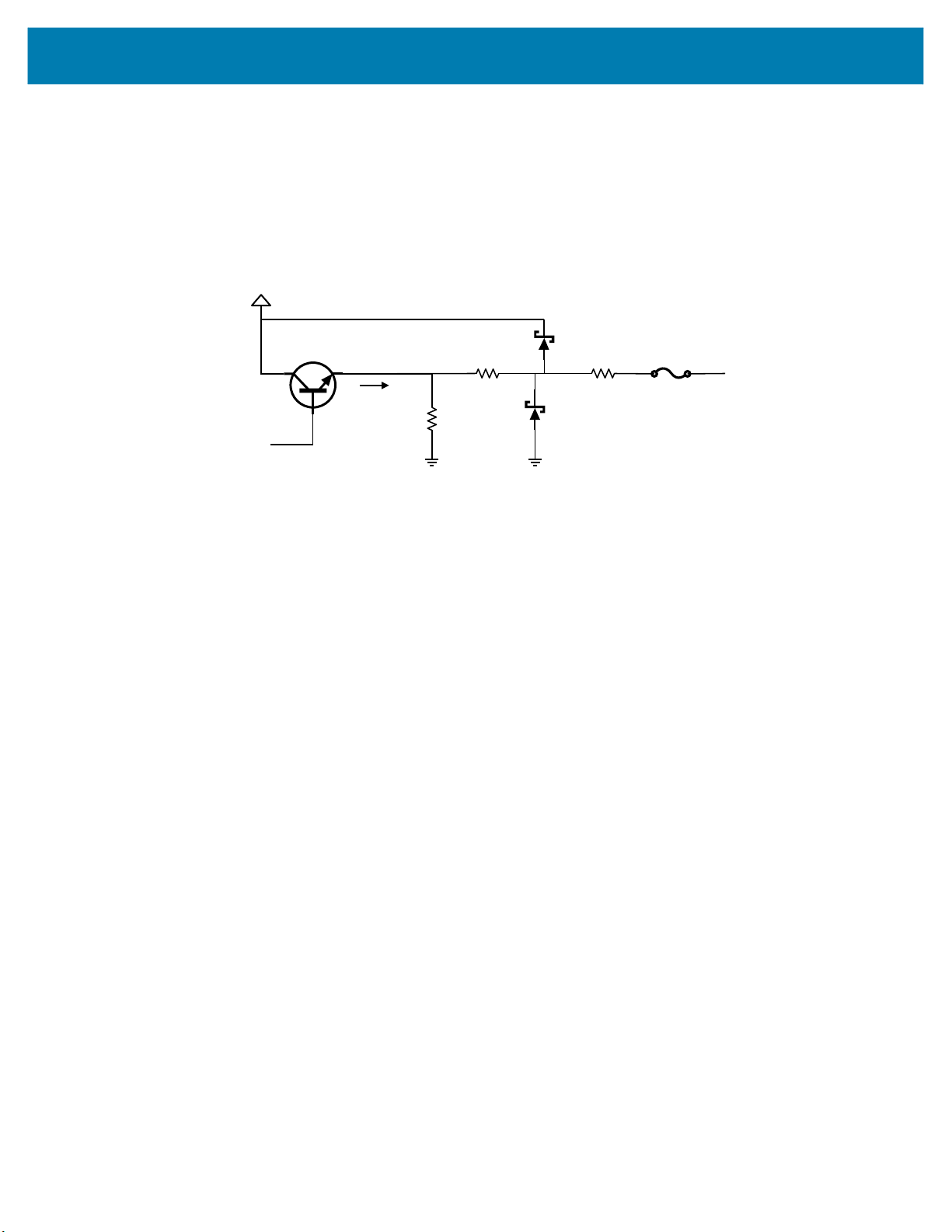
Analog Output
390ohms
10Vto30V
Analogcontrol
2.2K
ANALOG_OUT
I
out
10ohms
The vision system is equipped with an analog output on the External Light connector capable of generating
between 0 V and 10 V. An output impedance of approximately 400 ohms protects the analog output driver
against overload conditions, however, this introduces an offset in output voltage that is directly proportional
to the output current. For optimal accuracy, connect devices with low input bias current.
Figure 23 Analog Output Equivalent Circuit Diagram
51

Power and Thermal Management
Sophisticated algorithms keep operation of the machine vision system within acceptable power and
thermal parameters to ensure reliable operation over the product lifetime.
CAUTION: If the available power budget is not adequate for configured settings, a warning is indicated to the
user. In some cases, the user can choose to ignore or override the warning, in which case, operational stability of
the system should be evaluated by the integrator.
Temperature is actively monitored at critical points within the system. Whenever a safe limit is exceeded
the system response may include disabling of certain features, reduction of processor performance, or
stopping active jobs.
If overheating is a problem, effective mitigation strategies include:
• Reducing the average system power consumption
• Avoiding continuous trigger mode
• Lowering trigger rate
• Using external illumination
• Avoiding operating from PoE
• Operating in a cooler environment
• Actively cooling with a fan
• Heatsinking the chassis to a large thermally conductive mounting surface through a thermally
conductive mounting system
For optimal performance, ensure that the device does not exceed the recommended operating ranges
listed below
:
Table 19 Operating Temperature
Temperature Operating Range
Ambient Temperature
Note 1: If temperatures exceed the operating range, additional heat sinking strategies may be necessary,
i.e. mounting to a metal infrastructure or forced convection via an external fan. Use of the Zebra Universal
Mounting Bracket (BRKT-LMNT-U000) provides multiple options to mount to a metal infrastructure.
0°C - 40°C (POE, duty cycle-dependent)
0°C - 45°C (non-POE, duty cycle-dependent)
1
52

Zebra Aurora Software Overview
The Zebra Aurora application provides a unified platform with an intuitive interface for setting up, deploying, and
running Fixed Industrial Scanning or Vision System jobs to control enterprise-wide manufacturing and logistics
automation solutions. This tool also has the capacity to scale in support of new codes and increase scanning
speed with the potential to upgrade to machine vision functionality via software license upgrade.
Human-Machine Interface (HMI)
Using the Web Human-Machine Interface (HMI), operators can view and interact with the Zebra Aurora Human
Machine Interface (HMI) dashboard via web browser or by connecting a monitor directly to the xS40.
Industrial Ethernet Information
For information regarding built-in EtherNet/IP, PROFINET or other network protocols to integrate with any common
PLC or host system, refer to the FS/VS Smart Camera Industrial Ethernet User Guide.
Zebra Aurora Features
Zebra Aurora provides several differentiating features to rapidly process, evaluate and compare multiple images in
various lighting conditions without altering any hardware configurations.
Some notable features include:
• Golden Image Compare – allows users to efficiently identify and resolve issues by comparing any image to an
ideal image created at setup. This tool has the capacity to significantly expedite troubleshooting activities by
immediately diagnosing and correcting the source of degradation.
• QuickDraw – enables the user to draw right on an image to create a tool with minimum steps.
• Object Locate and Pattern Matching – Zebra’s algorithms and intuitively crafted default settings enable users to
consistently create and deploy efficient tools with less trial and error involved.
For additional information on leveraging these features toward a specific use case, refer to the built-in tutorials,
videos and walk-throughs available within the Zebra Aurora application.
53

Device Discovery
Emulated devices are listed under Virtual Devices on the Setup New Device screen. Devices that are physically
connected to the system and are available to connect and setup are listed under Existing Devices.
Figure 24 Setup a Device
Zebra Aurora Software Overview
NOTE: If you are experiencing issues using Device Discovery, see the Troubleshooting on page 41
and Security Settings on page 76 sections for potential solutions.
54

Zebra Aurora Software Overview
Setting an IP Address
Users can manually set up an IP address by clicking on the Add Via IP Address button in the bottom left corner of
the View Devices screen. To connect via IP address, enter the IP address into the Add New Device via IP
Address form field and click Connect.
Figure 25 Add a New Device via Static IP Address
Add Via IP
Address Button
55

Zebra Aurora Software Overview
Ethernet Setup
Users can physically connect the device via Ethernet to a Network Switch, Power over Ethernet Injector, or directly
to the Host PC. Users can also connect the device via USB-A to USB-C cable to the Host PC. Once connected,
navigate to the View Devices screen to view all connected devices and their properties such as name, model
name, IP address and the last time the device was accessed.
Figure 26 Main Screen
56

Zebra Aurora Software Overview
Configuring Device Settings
Device Settings that are configurable within the Zebra Aurora application include device details, communication,
general settings, and GPIO mapping. Users can add a description to a specific set up, proceed to configure
additional settings, or open the Job workflow to open an existing Job by importing a zjob file or creating a new one.
NOTE: Emulated device settings are read-only and cannot be edited by users.
Figure 27 Device Settings
57
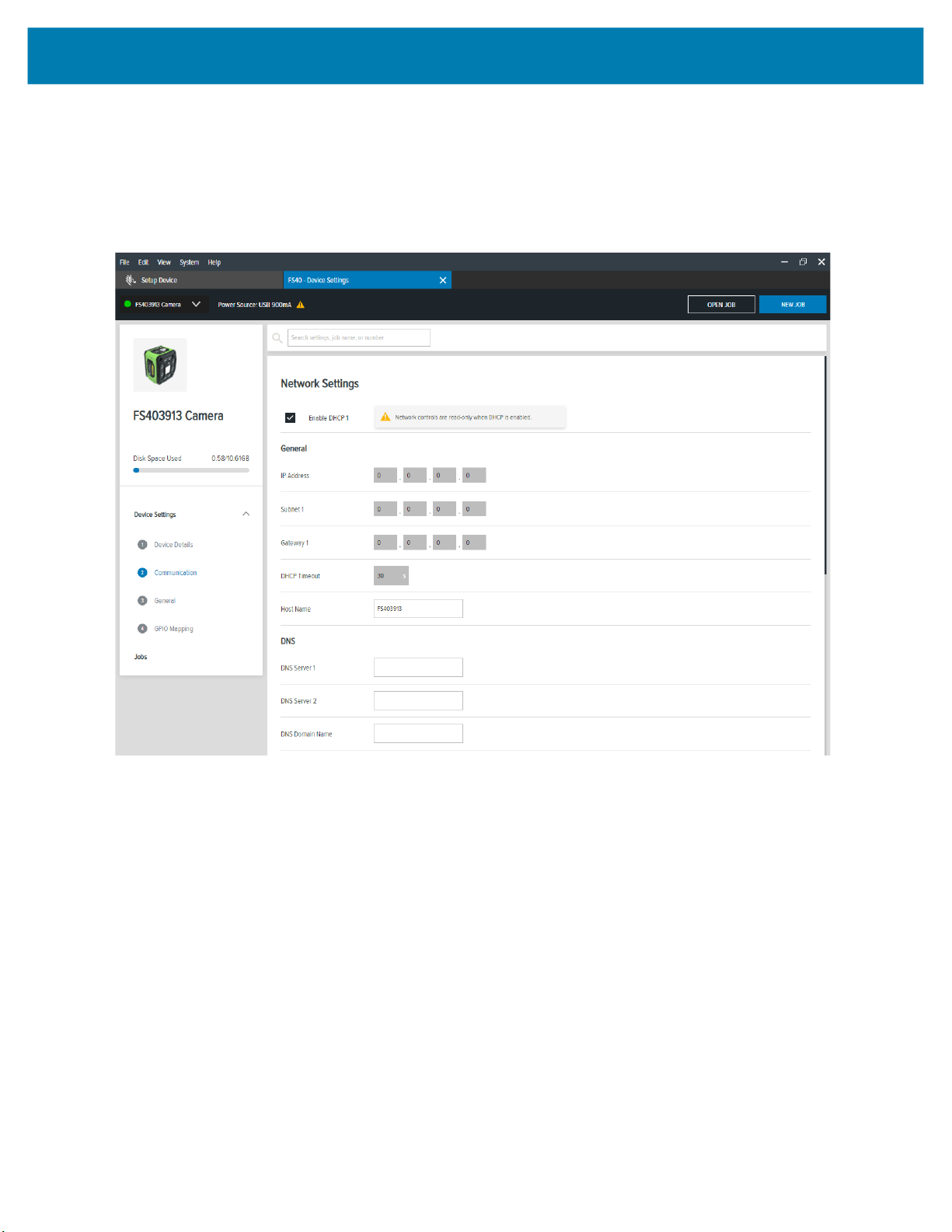
Zebra Aurora Software Overview
Communication Settings
Configurable communication settings include network settings, DNS, date/time, PLC protocol and USB settings.
For additional information on PLC protocol and Industrial Ethernet, refer to the FS/VS Smart Camera Industrial
Ethernet User Guide.
Figure 28 Communication
58

Zebra Aurora Software Overview
General Settings
Under general settings, users can configure the beeper, power, and 360° LED settings. Beeper settings can be set
to enable or disable and the volume, tone, and duration of the beep can be configured to fit the needs of a specific
use case. The power settings can be altered to enable unrestricted USB-A power. Settings on the 360° LED of the
device can be enabled to hold the flash until its next trigger. The number of flashes that occur and the length of
time per flash (.ms) can also be configured.
For additional information on the FS/VS Smart Camera user interface, see User Interface on page 40 and LED and
Beeper Indicators on page 42.
Figure 29 General Settings
59

Zebra Aurora Software Overview
GPIO Mapping
Configure GPIO settings including direction and signal type for both 12 pin and 5 pin connectors by accessing the
GPIO mapping tool. The direction of each GPIO can be edited by using the dropdown menu and selecting input,
output or none. For GPIO1 and GPIO3, the signal type can be changed to trigger or none. Input debounce on
GPIO1 and GPIO3 can be also be increased by clicking on the settings icon.
For more information on the GPIO operation, see General Purpose Input and Outputs on page 48.
NOTE: GPIO4-GPIO8 settings cannot be edited when the device is in low power mode.
Figure 30 GPIO Mapping Configuration
60

Zebra Aurora Software Overview
Building and Deploying Fixed Scanning (FS) Jobs
To set up a FS Job, users can set decoder parameters, symbologies, OCR settings, code quality metrics, and data
formatting rules. Begin by configuring the decode parameters and selecting the appropriate set of symbologies. A
symbology is chosen by clicking Symbologies Tab. Next, select specific symbologies to be deployed by clicking
the corresponding checkboxes.
Once the Job is in progress, monitor the Image Viewer and Filmstrip controls to view the Jobs progress. The
Image Viewer contains a status bar that displays the Job result and run time. In FS editor, the status bar will show
the decode time, decoded value, PPM and the type of symbology decoded.
View Results provides additional data on the decode, and displays the results for each Job instance.
Figure 31 FS Job Builder
61

Zebra Aurora Software Overview
Building and Deploying Vision System (VS) Jobs
To build and deploy a VS Job, start by selecting a machine vision tool and dragging it onto the FlowBuilder. Using
Flowbuilder, stack additional tools onto the workflow or configure the intended results to deploy the Job. To
streamline the creation of a specific toolset, use the QuickDraw tool.
Using the QuickDraw Tool
The QuickDraw tool provides an efficient way for users to rapidly select a region of interest on an image and deploy
a Job based on that region.
To use the QuickDraw tool:
1. Hold shift and click to create a region of interest by dragging the mouse on the ImageViewer.
2. From the QuickDraw menu, select a tool.
The selected tool then gets added to the FlowBuilder. From here, follow the Flowbuilder workflow to deploy the
Job.
Figure 32 QuickDraw Tool
Users can view the results of the Job in progress by monitoring the Image Viewer as it cycles through the images
on the Filmstrip in the lower left corner of the application
62
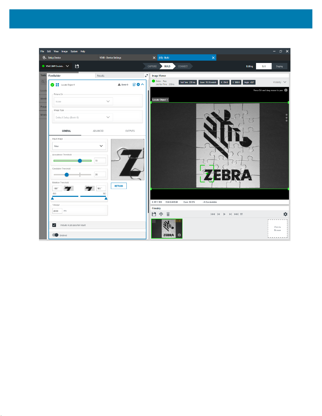
Figure 33 FlowBuilder
Zebra Aurora Software Overview
63
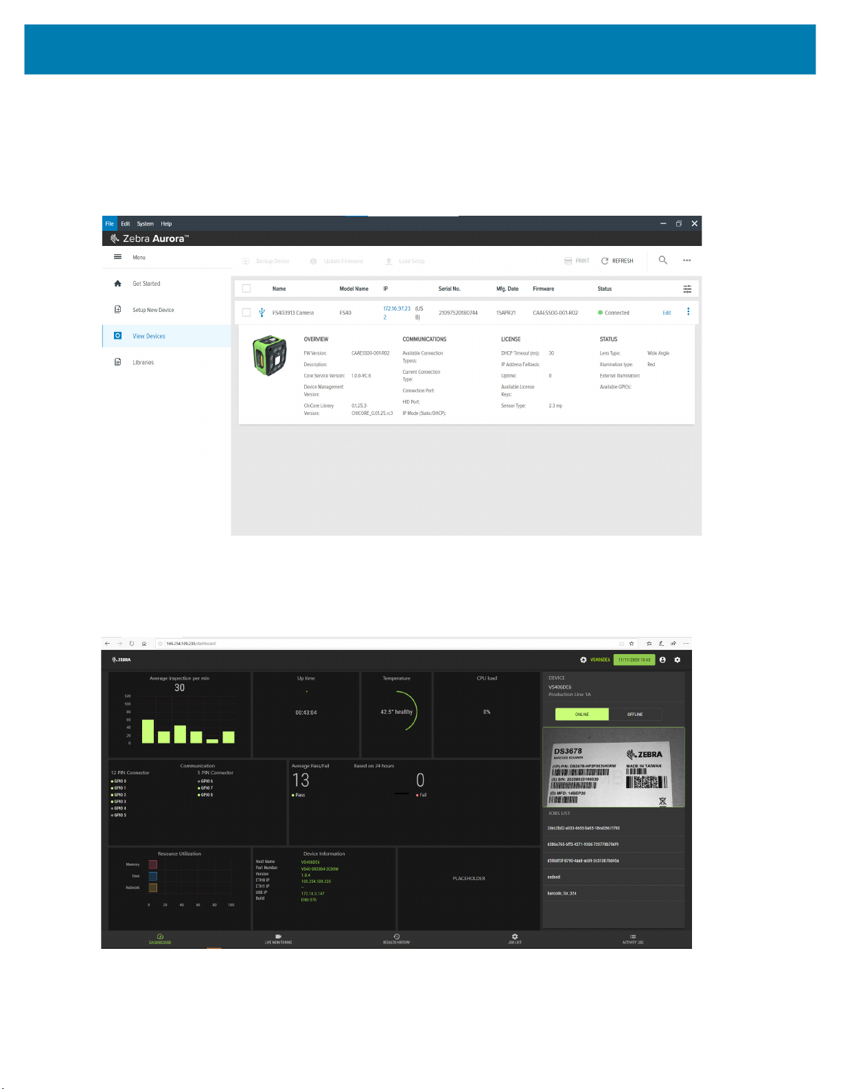
Zebra Aurora Software Overview
Accessing the Web Human-Machine Interface (HMI)
Access the Web HMI by entering the device IP address into a web browser. To obtain the device IP address, select
View Devices from the menu on the left of the Zebra Aurora application.
Figure 34 View Devices Screen
Once logged in to the Web HMI, the application presents a dashboard that provides key hardware metrics such as
average inspection per minute, total up time, temperature, CPU load, communication status, average pass fail, and
resource utilization.
Figure 35 Web HMI
Image Viewer
64

Zebra Aurora Software Overview
Live Monitoring with the Web HMI
The Live Monitoring feature to allows users to view decode results as they occur in real-time by clicking the Live
Monitoring tab on the bottom of the interface.
Figure 36 HMI Live Monitoring
Settings Icon
Live Monitoring Tab
The Web HMI also provides the capability to update the device firmware by selecting the settings icon in the top
right corner of the application.
Updating Firmware Using the Web HMI
On the settings screen, click the Firmware Update tab and click Choose File to select the file from the directory
and click the Update button.
Figure 37 Web HMI Settings
65

Zebra Aurora Software Overview
Below the Update button, the progress bar shows the completion percentage of the Firmware update in progress.
Once complete, a success or failure message appears to indicate the outcome of the update. On the device, the
LEDs flash red to indicate success. The device then automatically reboots and beeps.
To confirm that the firmware update was successfully completed, check the firmware version on the device in the
Device Information section of the Web HMI dashboard.
NOTE: A factory reset may be required to clear out oldXML and zjob files and replace them with newer
files.
Accessing the Device using the Web-HMI
To access the device via the Web HMI, open a browser and enter the known IP address of the reader.
1. If connected via USB:
• View the device label and note the hostname field.
Figure 38 Obtain Hostname from Label
• Open a web browser and enter http://<HOSTNAME> and press enter.
Figure 39 Enter Hostname into Browser
Figure 40 Access Web HMI
Alternatively, the device’s IP can be accessed directly by using six digits (shown below as X and Y) included in
the serial number.
66

Zebra Aurora Software Overview
• Example:
• 12XXX345678YYY - where the values for XXX and YYY form the third and fourth octet of the device’s USB
IP address:
• The USB IP address is in the format: 172.16.XXX.YYY
• If XXX is less than 256; XXX; otherwise XXX = XXX Modulo 256
• If YYY is less than 256, YYY; otherwise YYY = YYY Modulo 256.
The two examples below show how to calculate the USB IP address:
• Example 1: Both XXX and YYY are less than 256
SN:21097520180161
XXX = 097
YYY = 161
USB IP Address = 172.16.97.161
• Example 2: XXX is greater than 256 and YYY is greater than 256:
SN:21364520180597
XXX = 364 (Since this value is greater than 256, perform a Modulo operation)
XXX = 364%256 = 108
YYY = 597 (Since this value is greater than 256, perform a Modulo operation)
YYY = 597%256 = 85
USB IP Address = 172.16.108.85
2. If connected via Ethernet directly to the PC:
• The IP address should fit the format 169.254.x.y., where x and y are the last four characters of the MAC
address converted from hex to decimal.
• Example:
• MAC Address: 78:b:d6:5c:6d:f2
• 6D (hex) - 109 (decimal)
• F2 (hex) - 242 (decimal)
• IP = 169.254.109.242
3. If connected via Ethernet to a network via switch or hub, use the DHCP address from the network/router
configuration.
For all connection methods, users are also able to access the device via hostname instead of IP address. The
hostname consists of the device part number and the last four characters of the MAC address:
• Example:
• Part Number - VS40
• MAC Address - 78:b:d6:5c:6d:f2
• Hostname = VS406df2
For the latest information on performing a firmware update, refer to
67
zebra.com/support

Factory Reset
To restore the factory settings on the device, use the Zebra Aurora application to navigate to the View Devices tab
from the menu. Next, select the device to be reset and click on the dropdown to select Factory Reset to restore
factory settings on the device.
Figure 41 Factory Reset on the Aurora Application
Zebra Aurora Software Overview
68

Zebra Aurora Software Overview
Software License Activation Methods
Users can activate their license via the desktop software or USB-C dongle.
Activating a License with Zebra Aurora
To connect to the device from the Zebra Aurora application when it is online, launch the browser from within the
application to connect to the Web HMI and enter the Activation ID.
To activate a license if the device is offline (intranet) or USB-only:
1. Connect the device to the desktop application.
2. From the License Manager screen, navigate to the license file.
3. Download the license file to the device.
Activating a License via USB-C Dongle
To activate a license via USB-C dongle:
1. Stage the USB-C dongle with the license files (downloaded from the portal).
2. Plug in the USB-C dongle into the device to update the license.
69

Supported Symbologies
The following table lists the supported symbologies for the FS/VS Smart Camera Series.
Table 20 Supported Symbologies
Type Symbology
1D Base 32 (Italian Pharma), Codabar/NW7, Code 11, Code
2D Aztec, Composite Codes, DataMatrix, Dotted DataMatrix,
OCR OCR-A, OCR-B, MICR, US Currency, Trainable OCR
Machine Vision Toolsets
The following table lists the various toolsets supported by Zebra Aurora.
Zebra Aurora Software Overview
39, Code 128, GS1 Databar, I 2 of 5, UPC/EAN, DPM
DotCode, MaxiCode, PDF417, Micro PDF417, QR Code,
Micro QR, DPM
(available on select models or via OCR license)
Table 21 Machine Vision Toolsets
Toolset
Tool Description Sensor Standard Advanced
Object Locate Find high contrast features. O O O
Pixel Counter Count pixels with a set/given grey level in a
specific area.
Brightness Provides the average brightness for an area. O O O
Contrast Provides the average contrast for an area. O O O
Edge Tool Find edges for fixturing O O O
Distance Tool Measure the distance between two existing
tool results.
Advanced Pattern Find complex features. _ O O
Blob Find, sort and count areas of joined pixels with
a similar grey level.
Predefined OCR Identifies the presence of text and corrects:
OCR-A, OCR-B, US Currency, MICR.
Optical Character
Verification (OCV)
Find Circle Find and measure circles. - O O
Caliper Tool Find and measure the distance between two
Filters Enhance image quality for more robust
1D/2D/DPM Read 1D, 2D, and DPM barcodes. - O O
Trainable OCR Create a unique text library/read any font. - - -
Inspects the quality of joined pixels with a
similar grey level.
edges.
inspection.
O O O
O O O
_ O O
- O O
- O O
- O O
- O O
Boxes marked with an O are supported by the specified toolset.
70

Zebra Aurora Software Overview
Table 21 (Continued)Machine Vision Toolsets
Toolset
Tool Description Sensor Standard Advanced
Flaw Detection Detects complex defects. - - -
Metrology Precise measurement tools. - - -
Bead Inspection Find and measure RTV and other applied
adhesive beads.
Boxes marked with an O are supported by the specified toolset.
- - -
71

Troubleshooting
This section describes potential issues that could arise while using the device and solutions that could correct
the problem such as power cycling and pinging the device. Ensure that you are familiar with the recommended
security settings to use the device and the communication ports that the Zebra Aurora application utilizes by
referring to Security Settings on page 74 and Zebra Aurora Communication Port Usage on page 75.
Table 22 Troubleshooting the Device
Problem Cause Solution
Device is not connecting to network
when using Device Discovery.
Device is cycling power or data
connection on USB port.
Specific ports that are utilized by
the application are blocked by
Windows Defender Firewall.
Ensure that the device is visible
in the Windows Network by
viewing the File Explorer and
selecting Network.
There is no RNDIS driver
available to the device when
connected vis USB.
USB cable may be loose or
intermittent.
Ensure that Zebra Aurora has
access to Domain, Public and
Private networks.
See Security Settings on
page 74 for additional
information.
If the device is not viewable
under the Network dropdown
or listed under Other
Devices, it is not connected.
To verify that there is a NDIS
driver, go to the Windows
Device Manager and search
under the Network Adapters
dropdown.
Reseat the USB cable and
tighten locking screws firmly.
See Power Cycling the
Device on page 73 for
additional information.
71

Troubleshooting
Communicating with the Device
Two common strategies that can be employed to communicate with the device are pinging via IP and
pinging via hostname.
Pinging the Device via IP
To ping the device via IP address:
1. Open a command prompt or powershell.
2. Enter the following command:
i.ping<ip address>
3. Check to see if the device responds or fails to respond.
• Example:
Pinging 192.168.4.100 with 32 bytes of data:
Reply from 192.168.4.100: bytes= 32 time=1ms TTL=64
Reply from 192.168.4.100: bytes= 32 time=1ms TTL=64
Reply from 192.168.4.100: bytes= 32 time=1ms TTL=64
Pinging the Device via Hostname
To ping the device via hostname:
1. Open a command prompt or powershell.
2. Enter the following command (assuming the Hostname is FS20b1cc
i.ping FS20b1cc.local
NOTE: The above hostname example uses the Avahi service running in the device.
3. Check to see if the device responds or fails to respond.
• Example:
Pinging 192.168.4.100 with 32 bytes of data:
Reply from 192.168.4.100: bytes= 32 time=1ms TTL=64
Reply from 192.168.4.100: bytes= 32 time=1ms TTL=64
Reply from 192.168.4.100: bytes= 32 time=1ms TTL=64
72

Troubleshooting
Device Discovery Troubleshooting Methods
Two common solutions to enable the device to re-connect via device discovery are performing a factory
reset on the device and power cycling the device.
Factory Reset the Device
To factory reset the device using the hardware buttons:
1. Disconnect all power sources.
2. Press and hold the TRIG button on the camera.
3. Connect to a power source.
4. Continue to hold the TRIG button. After 20 seconds, the LEDs on the device turn amber.
5. Immediately release the TRIG button once the LED turns amber and release within five seconds.
For information on how to perform a factory reset using the Web HMI, see Factory Reset on page 68.
Power Cycling the Device
To power cycle the device:
1. Remove all cables to ensure that no power is being directed to the device.
2. Reinsert a power source and allow the device approximately one minute to boot up.
3. Re-attempt to:
• Discover a device in Aurora by restarting the application and clicking View Devices.
• View a device in the Windows Network
• Access a device using the Web HMI
If failure persists, repeat the steps above for all of the connection types being used with the device,
including:
• USB-to-PC
• Ethernet directly to the PC (this requires a 24 V connection for power).
• Ethernet connected to a network via switch or hub (this requires a 24 V connection to a power
source if not using Power over Ethernet).
NOTE: If both Ethernet and USB are connected simultaneously, device discovery attempts to fins the
USB-based IP address by default.
73
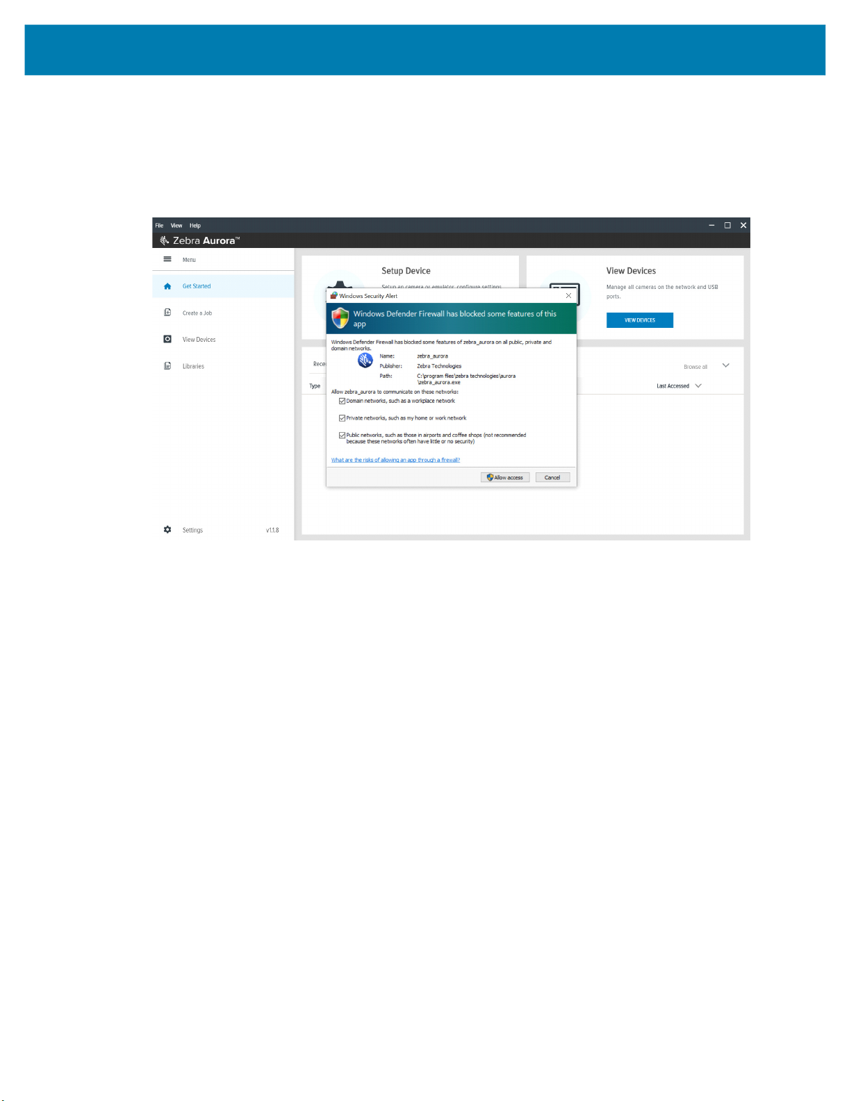
Security Settings
To ensure that all available application functionalities are enabled, select all three checkboxes in the
Windows Defender Firewall settings window as shown in Figure 39 and click Allow Access.
Figure 39 Windows Defender Firewall Settings
Troubleshooting
These settings can be configured by clicking Change Settings and enabling the domain, private and public
network settings for Zebra Aurora and Network Discovery applications. For specific information on the
communication ports utilized by the Zebra Aurora application, see Zebra Aurora Communication Port
Usage on page 75.
74

Troubleshooting
Zebra Aurora Communication Port Usage
The table below displays the ports utilized by the Zebra Aurora application
Table 23 Communication Port Usage
Item TCP UDP
FTP - Data 20
FTP - Communication 21
DHCP Server 67
DHCP Client 68
Web HMI 80 443
NTP 123
Modbus 502 502
EtherNet/IP 2222
Discovery Port 3702 3702
TCP Port 4444
mDNS 5353
mDNS Responder 5354
Listening Port 5555 5555
Communication Port 5556 5556
Output Image 7722 7722
Image Live VIew 7777 7777
Discovery Port (2) 8889
Discovery Port (3) 9876
Raw TCP Data 25250
Profinet RT Unicast 34962 34962
Profinet RT Multicast 34963 34963
Profinet RT CM 34964 34964
EtherNet/IP 44818 44818
Profinet 49152
75

Maintenance
This section describes the maintenance procedures that must be followed to maintain the FS/VS Smart
Camera’s performance.
Maintenance
Known Harmful Ingredients
The following chemicals are known to damage the plastics on Zebra scanners and should not come in contact
with the device:
• Acetone
• Ammonia solutions
• Aqueous or alcoholic alkaline solutions
• Aromatic and chlorinated hydrocarbons
• Benzene
• Bleach
• Carbolic acid
• Compounds of amines or ammonia
• Ethanolamine
• Ethers
• Ketones
• TB-lysoform
• Toluene
• Trichloroethylene
Approved Cleaning Agents
The following cleaning agents are approved for cleaning the plastics on Zebra scanners:
• Pre-moistened wipes
• Isopropyl alcohol 70%
76

Maintenance
Tolerable Industrial Fluids and Chemicals
NOTE: Not all fluid variants and brands have been tested.
The following industrial fluids and chemicals were evaluated and deemed tolerable for the FS/VS Smart
Camera series.
• Motor/Engine Oil
• Automatic Transmission Fluid (ATF)
• Continuously Variable Transmission Fluid (CVT)
• Industrial De-Greaser (Engine Brite Heavy Duty)
Cleaning the Device
Routinely cleaning the exit window is required. A dirty window may affect scanning accuracy. Do not allow
any abrasive material to touch the window.
To clean the device:
1. Dampen a soft cloth with one of the approved cleaning agents listed above or use pre-moistened
wipes.
2. Gently wipe all surfaces, including the front, back, sides, top and bottom. Never apply liquid directly to
the scanner. Be careful not to let liquid pool around the scanner window, trigger, cable connector or any
other area on the device.
3. Be sure to clean the trigger and in between the trigger and the housing (use a cotton-tipped applicator
to reach tight or inaccessible areas).
4. Do not spray water or other cleaning liquids directly into the exit window.
5. Wipe the scanner exit window with a lens tissue or other material suitable for cleaning optical material
such as eyeglasses.
6. Immediately dry the scanner window after cleaning with a soft non-abrasive cloth to prevent streaking.
7. Allow the unit to air dry before use.
8. Scanner connectors:
a. Dip the cotton portion of a cotton-tipped applicator in isopropyl alcohol.
b. Rub the cotton portion of the cotton-tipped applicator back-and-forth across the connector on the
Zebra scanner at least 3 times. Do not leave any cotton residue on the connector.
c. Use the cotton-tipped applicator dipped in alcohol to remove any grease and dirt near the connector
area.
Use a dry cotton tipped applicator and rub the cotton portion of the cotton-tipped applicator back-and-forth
across the connectors at least three times. Do not leave any cotton residue on the connectors.
77

www.zebra.com
 Loading...