

Page 1

FS/VS Smart
Camera Series
Industrial Ethernet Guide
MN-003811-01EN Rev A
Page 2

ZEBRA and the stylized Zebra head are trademarks of Zebra Technologies Corporation, registered in
many jurisdictions worldwide. All other trademarks are the property of their respective owners. ©2021
Zebra Technologies Corporation and/or its affiliates. All rights reserved.
Information in this document is subject to change without notice. The software described in this document
is furnished under a license agreement or nondisclosure agreement. The software may be used or copied
only in accordance with the terms of those agreements.
For further information regarding legal and proprietary statements, please go to:
SOFTWARE:zebra.com/linkoslegal
COPYRIGHTS:zebra.com/copyright
WARRANTY:zebra.com/warranty
END USER LICENSE AGREEMENT: zebra.com/eula
Terms of Use
Proprietary Statement
This manual contains proprietary information of Zebra Technologies Corporation and its subsidiaries
(“Zebra Technologies”). It is intended solely for the information and use of parties operating and
maintaining the equipment described herein. Such proprietary information may not be used, reproduced,
or disclosed to any other parties for any other purpose without the express, written permission of Zebra
Technologies.
Product Improvements
Continuous improvement of products is a policy of Zebra Technologies. All specifications and designs are
subject to change without notice.
Liability Disclaimer
Zebra Technologies takes steps to ensure that its published Engineering specifications and manuals are
correct; however, errors do occur. Zebra Technologies reserves the right to correct any such errors and
disclaims liability resulting therefrom.
Limitation of Liability
In no event shall Zebra Technologies or anyone else involved in the creation, production, or delivery of the
accompanying product (including hardware and software) be liable for any damages whatsoever
(including, without limitation, consequential damages including loss of business profits, business
interruption, or loss of business information) arising out of the use of, the results of use of, or inability to
use such product, even if Zebra Technologies has been advised of the possibility of such damages. Some
jurisdictions do not allow the exclusion or limitation of incidental or consequential damages, so the above
limitation or exclusion may not apply to you.
2
Page 3

Revision History
Revision Description
MN-003811-01 Rev. A 6/21 Initial Rev A. Release
3
Page 4

Contents
Terms of Use ......................................................................................................................... 2
Proprietary Statement ......................................................................................................... 2
Product Improvements ........................................................................................................ 2
Liability Disclaimer .............................................................................................................. 2
Limitation of Liability ............................................................................................................ 2
Revision History .................................................................................................................... 3
About This Guide
Service Information ............................................................................................................... 7
Initial Setup
Hardware/Software Prerequisites ......................................................................................... 8
Activating Industrial Ethernet ................................................................................................ 9
Configuring Industrial Ethernet Input & Output ................................................................... 10
User Control Data ............................................................................................................. 10
Results Data ..................................................................................................................... 11
Industrial Ethernet Interface
Job Control/Status ............................................................................................................... 12
Trigger Control/Status ......................................................................................................... 14
Results Control/Status ........................................................................................................ 15
User Data Control/Status .................................................................................................... 16
Error Codes Control/Status ................................................................................................. 16
User Control and Data Structure ......................................................................................... 17
User Data Format for Raw Mode (Mode = 1) ................................................................... 17
User Data Format for Entry Mode (Mode = 0) .................................................................. 18
Results Status and Data Structure ...................................................................................... 18
Results Data Format Raw Mode (Mode = 1) .................................................................... 19
Results Data Format for Entry Mode (Mode = 0) .............................................................. 19
Entry Type List .................................................................................................................... 20
Fixed Scanning Barcode Results Structure ........................................................................ 20
Pattern Match Results Structure ......................................................................................... 21
4
Page 5

EtherNet/IP
Contents
Electric Data Sheet (EDS) File ............................................................................................ 22
TCP/IP Interface Object ...................................................................................................... 22
I/O Assemblies .................................................................................................................. 22
Status and Results Assembly (Device to PLC) ........................................................... 22
I/O Connections ................................................................................................................ 23
Exclusive Owner Connection ...................................................................................... 23
Configuring Rockwell ControlLogix Communication ........................................................... 24
Register the FS/VS EDS File ............................................................................................ 24
Method One: Download from the Device ............................................................................ 24
Method Two: Manually Install from the Developer Zip File ......................................... 24
Adding the FS/VS Smart Camera to the I/O Configuration ............................................... 25
FS/VS Smart Camera I/O Tags ........................................................................................... 26
Status and Results Input Assembly .................................................................................... 27
Job Control and Setup Assembly ........................................................................................ 28
Fixed Scanner Add-On Instruction (AOI) ............................................................................ 29
Creating a New Project that Uses AOI_FixedScanner ...................................................... 29
Using the Fixed Scanner Add-On Instruction ...................................................................... 35
PROFINET Interface
GSDML File ......................................................................................................................... 36
PROFINET IO Modules ....................................................................................................... 36
Command IO Module ........................................................................................................ 36
CommandData32 IO Module ............................................................................................ 37
CommandData64 IO Module ............................................................................................ 37
CommandData128 IO Module .......................................................................................... 37
Response IO Module ........................................................................................................ 38
ResponseData32 IO Module ............................................................................................. 39
ResponseData64 IO Module ............................................................................................. 39
ResponseData128 IO Module ........................................................................................... 39
Configuring Siemens S7 Communications .......................................................................... 40
Register the GSDML File .................................................................................................. 40
Finding the Device and Configuring the Device Name ..................................................... 40
Adding the FS/VS Smart Camera to the I/O Configuration ................................................. 42
Fixed Scanner Function Block (FB) .................................................................................... 44
Creating a Project that uses FB_FixedScanner ................................................................ 44
Using the Fixed Scanner Function Block .......................................................................... 48
Modbus TCP Interface
Modbus Register Locations ................................................................................................. 49
Command Registers Mapping ............................................................................................. 50
Command Data Registers Mapping .................................................................................... 50
Response Register Mapping ............................................................................................... 50
Response Data Registers Mapping .................................................................................... 51
Typical Use Case for Triggering a Job ................................................................................ 52
5
Page 6

Error Codes
Contents
6
Page 7

About This Guide
The FS/VS Smart Camera Industrial Ethernet Guide provides instructions for setting up and programming
the device for Industrial Ethernet applications.
IMPORTANT: If you have a problem with your equipment, contact Zebra Global Customer Support for your
region. Contact information is available at: zebra.com/support
Service Information
If you have a problem with your equipment, contact Zebra Global Customer Support for your region.
Contact information is available at: zebra.com/support
When contacting support, please have the following information available:
• Serial number of the unit
• Model number or product name
• Software type and version number.
.
Zebra responds to calls by email, telephone or fax within the time limits set forth in support agreements.
If your problem cannot be solved by Zebra Customer Support, you may need to return your equipment for
servicing and will be given specific directions. Zebra is not responsible for any damages incurred during
shipment if the approved shipping container is not used. Shipping the units improperly can possibly void
the warranty.
If you purchased your Zebra business product from a Zebra business partner, contact that business
partner for support.
7
Page 8

Initial Setup
Refer to the FS/VS Smart Camera Product Reference Guide for detailed information on:
• Connection Diagrams, including how to power the device.
• Status Indicators (LED and Beeper) and their meanings.
• Default Factory Settings, including how to restore Factory Settings.
• Ethernet Setup, including how to discover a device and set an IP address.
• Firmware update methods.
• Building and deploying Jobs, including configuration of Trigger modes.
• Accessing the Web HMI
• Licensing and Security
Hardware/Software Prerequisites
The following list of components is required for initial setup, testing, and development of Industrial Ethernet
applications that use the FS/VS Smart Camera.
• An FS/VS Smart Camera with Ethernet support that is configured to the correct Industrial Ethernet
Protocol and IP address. The device should be configured with the Jobs required to perform the work
needed by the Industrial Ethernet application.
• An M12 X-Coded cable that can connect the FS/VS Smart Camera Ethernet port to your network.
• The appropriate cabling and power supply necessary to power the FS/VS Smart Camera.
• A PC running Windows 7 or higher (Windows 10 recommended) to view the Web HMI, Zebra’s Aurora
Application, and development software for PLC applications.
• An Ethernet switch or router (if not connecting FS/VS Smart Camera directly to a PLC).
• An Industrial Ethernet PLC (Programmable Logic Controller) that supports one of the supported protocols
(EtherNet/IP, PROFINET, or Modbus TCP) and an Ethernet switch or router (if not connecting the device
directly to a PLC).
NOTE: Industrial Ethernet testing has been performed with the following PLCs and software:
Rockwell Compact Logix 5069-L306ER and Logix Studio 5000 v32.02.00 Software
Siemens S7 1500/1200 PLC and Totally Integrated Automation (TIA) v15.1 Software.
• FS/VS Smart Camera Industrial Ethernet Developer Files (CAAFSS00-001-Rxx.zip)
8
Page 9
Activating Industrial Ethernet
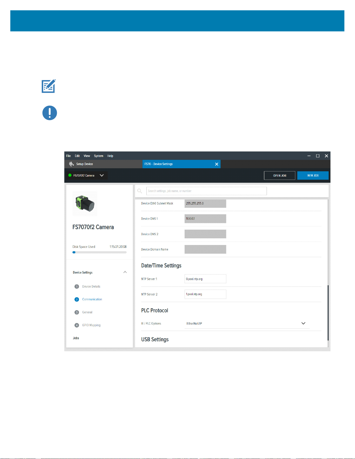
The Zebra Aurora Application device settings provide an option to select which PLC protocol can be
enabled on the device, as shown in the PLC Protocol selection in the figure below.
IMPORTANT: It is required that on any PLC Protocol change, the device must be rebooted for the
change to go into effect.
IMPORTANT: After enabling PROFINET protocol support, the FS/VS Smart Camera is only
accessible on the network through the PROFINET protocol. It is recommended that after enabling the
protocol you use the TIA Portal to find all the accessible devices and set the PROFINET device name
of the FS/VS Smart Camera.
Figure 1 PLC Protocol
Initial Setup
9
Page 10
Initial Setup
Configuring Industrial Ethernet Input & Output
Users can specify what results and configuration is provided to the PLC through the Zebra Aurora
applications Connect workflow. When Connect is selected, click the Industrial Ethernet list item on the
left of the application.
Figure 2 Connect
NOTE: The updated Job must be deployed and set as active on the device for any changes to be seen
from the PLC.
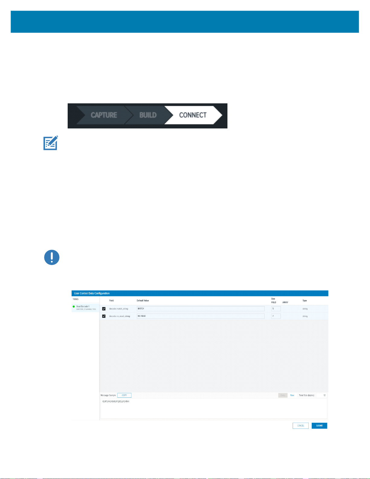
User Control Data
The User Control Data user interface allows for the PLC to make runtime changes to Job input parameters,
such as Barcode Match Strings or No Read strings.
Click the Add or Edit button to display the User Control Data Configuration dialog and the possible input
parameters. Check the specific input parameter to be changed from the PLC and configure the default
value and the size. Refer to the Message Sample window for a view of what the data must look like when
sent from the PLC to the device. For User Control Data, it is recommended that Raw Mode is selected.
This removes the need to set the proper Entry header for Entry mode. When the form is complete, click the
Submit button. From the main window, reorder the input parameters using a drag and drop technique.
IMPORTANT: Default value changes do not affect the job, they are used for Message Sample preview
only.
Figure 3 User Control Data Configuration
10
Page 11
Results Data
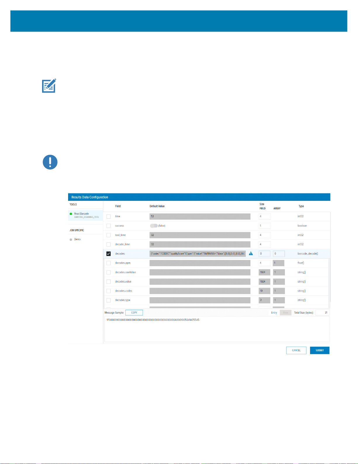
The Results Data user interface allows for the user to control which results are sent to the PLC upon Job
completion.
NOTE: The default barcode job on the FS/VS device is configured to provide the FS Barcode
Structure to the PLC. Also, new FS Jobs have FS Barcode Structure automatically configured as the
result output to the PLC.
Click the Add (or Edit) button to display the Results Data Configuration Dialog and the possible tools and
output parameters that can be added to the Result Data. Check the result parameter you intend to receive
from the FS/VS Smart Camera when a Job completes. Refer to the Message Sample window for a view of
what the data looks like when sent to the PLC. Entry or Raw mode can be selected, for more information
on these modes refer to the Results Status and Data Structure on page 18. Once complete, click the
Submit button. From the main window, reorder the result data items using a drag and drop technique.
IMPORTANT: Default value changes do not affect the job, they are used for Message Sample preview
only.
Figure 4 Results Data Configuration
Initial Setup
11
Page 12

Industrial Ethernet Interface
All Industrial Ethernet protocols supported by the FS/VS Smart Camera use the interface described in this
chapter. Review this section before proceeding to the specific Industrial Ethernet protocol section relevant
to your use case.
Job Control/Status
The FS/VS Smart Camera runs scripts, also known as Jobs, to decode barcodes and solve machine vision
problems. This section includes information on Job Control and Status features available to the PLC
programmer.
Table 1 Job Control/Status Features
Name Direction
Job
Control
Reset
Counters
Job Slot
Control
Job Slot
Number
PLC to Device 1 Job Control sets the state of the Job. When set to 0, the Job is
PLC to Device 1 When this bit is toggled from 0 to 1, all Job counters are reset.
PLC to Device 1 Job Slot Control is used in conjunction with the Job Control bit.
PLC to Device 2 This number field is used in conjunction with the Job Slot
Size
(Bits)
Description
inactive (stopped, for example, no Job loaded or not active).
When the value is set to 1 while the Job Slot Control bit is 0, the
default (or last active) Job will be loaded and set to the loaded
or active state. If the Job Slot Control bit is 1, the Job specified
by the Job Slot Number is loaded and set to the Loaded or
Active state.
If a Job load fails, an error code will be provided as specified in
Error Codes section.
the
As a result, the Job sequence number will be reset to 1 and any
remaining results in the Result Queue will be cleared.
When this bit is set to 1 and the Job Control bit is toggled from 0
to 1, a Job slot switch occurs. The Job that is loaded and made
active is then specified in the Job Slot Number field.
Control bit and the Job Control bit. When the Job Slot Control
bit is set and the Job Control bit is toggled from 0 to 1, this
number will indicate the Job that will be Loaded and made
active. If the number is 0, the Job will be unloaded (made
inactive).
12
Page 13

Industrial Ethernet Interface
Table 1 Job Control/Status Features (Continued)
Name Direction
Job Status Device to PLC 1 Job Status indicates whether a Job is in the loaded or active
Active Job
Slot
Number
Results
Job Slot
Number
Job Pass Device to PLC 1 This bit is set to 1 if the Job results pass, or set to 0 if the Job
Job Fail Device to PLC This bit is set to 1 if the Job results fail, or set to 0 if the Job
Echo
Register
Control
Echo
Register
Status
Device to PLC 16 The Active Job Slot Number represents the Current Job Slot.
Device to PLC 16 The Results Job Slot Number represents the Results Job Slot.
PLC to Device 16 This 16-bit value is reflected in the PLC based on the value that
Device to PLC 16 This 16-bit value matches the value that the PLC writes to its
Size
(Bits)
Description
state or in the Unloaded Stopped state. Depending on the Jobs
trigger type, a Loaded Job may either be Running or Idle
(waiting on trigger).
0 = Stopped/Unloaded, 1 = Active/Loaded.
Under normal conditions (non-error conditions) this bit matches
the Job Control bit.
This 16-bit integer corresponds to the Job slot of the currently
Loaded or Active Job.
This 16-bit integer corresponds to the Job slot of the Job that
was run to produce the results in the Results data section.
results fail.
results pass.
Some error conditions may not be considered to be a fail, refer
Error Codes section for additional information.
to the
the PLC writes to it. This field allows the PLC programmers to
verify that the output assembly has been written to the camera
when this value matches the written value.
Echo Register Control. This field allows the PLC programmers
to verify that the output assembly has been written to the
camera when this value matches the written value.
13
Page 14

Trigger Control/Status
Each Job will have one of the following trigger modes:
• Single Shot
• Continuous
• Presentation
• Burst
• Level
Depending on the Trigger Mode, the action that the device takes when an external Trigger is initiated may
differ. For example, when a Job is set for Single Shot, a PLC/GPIO Trigger initiates a single run of that Job.
However, if the Job is set to Continuous, a PLC/GPIO Trigger may produce no change in behavior. Refer
to the Trigger Modes Configuration section in the FS/VS Smart Camera Series Product Reference Guide
for additional information.
The following table describes the control and status of Trigger functionality as it relates to Industrial
Ethernet.
Table 2 Trigger Modes
Industrial Ethernet Interface
Name Direction
Trigger Enable
Control
Trigger PLC to Device 1
PLC to Device 1 Set to 1 to enable triggering
Size
(Bits)
Description
Set to 0 to ignore trigger
When changed from 0 to 1, the current Job begins
running or processing. This bit is only acted upon when
the following conditions are met:
• Job Status is 1 (Job is loaded/active)
• Trigger Ready is 1 (Device is ready to accept
triggers)
Trigger Ready Device to PLC 1 Indicates when the device is ready to accept a new
trigger. This bit is set to 1 when Trigger Enable Control
is 1 and the active Job Slot is not 0. If the bit is set to 0,
the triggers will be ignored.
Trigger Status Device to PLC 1 This bit is set to 1 when the Job is currently executing or
running. This bit is cleared when the Job is stopped or
idle.
14
Page 15

Results Control/Status
Job results are made available upon completion of the Job. The result data is dependent upon the type of
Job that is run and the Job that was configured. If multiple results are made available before the PLC can
process them, it is suggested that Results Buffering is enabled to ensure that no results are lost.
Table 3 Results Data
Industrial Ethernet Interface
Name Direction
Results Buffer
Control
Results Ack PLC to Device 1 This bit is only applicable when Results Available is set to
Results
Available
Results Buffer
Overflow
Results Queue
Count
Result Data Device to PLC Array of
Results Packet
Sequence
PLC to Device 1 Results Buffer Control enables the queuing of result data
Device to PLC 1 Indicates that a new set of read results are available. This
Device to PLC 1 Indicates that the device has discarded a set of read results
Device to PLC 8 Results Queue Count records the number of results
PLC to Device 16 This number is used in conjunction with Results Ack. It is
Size
(Bits)
Bytes
Description
(queue size is set to 32). If set to 1, new results are queued
on the device and remain present until acknowledged. To
retrieve the next set of results from the queue on the
Results Ack, the bit must transition from 0 to 1. The device
responds to this acknowledgment by clearing the Results
Available bit when no more results are queued on the
device. See the Results Queue Count row in this table for
more information on how results are queued on the device.
If results buffering is not enabled (set to 0), newly received
read results overwrite the content of the Result Data in the
Response/Status section of the Input Assembly.
The Results Overflow bit is set when this bit is set and there
is no more space in the queue to accept a new result.
1. When this bit transitions from 0 to 1, the PLC is then sent
the next set of results. If there are no additional results
queued on the device, the Results Available bit is cleared.
bit is cleared when the results are acknowledged.
because the results queue is full. This is cleared when the
next set of results are successfully queued.
currently in the queue on the device. This bit is set to 0 if
there are no results in the queue.
Results Status and Data Structure on page 18 for
See
more information on contents of the Results Data Structure.
expected to be changed before Results Ack is set to ensure
that Result Ack is not missed by the device.
15
Page 16

User Data Control/Status
A PLC program can modify Job input parameters at runtime through User Data Control. Updating Job input
parameters are not permanent and are reset to the Job defaults if the Job is reloaded.
Table 4 User Data
Name Direction Size (Bits) Description
User Data
Control
User Data
Status
User Data PLC to
PLC to
Device
Device to
PLC
Device
Industrial Ethernet Interface
1 When this bit is toggled from 0 to 1, the current Job’s
User Data will be overwritten with data provided by the
PLC. See the User Data Status bit description to know
when the User Data has taken affect. When this bit is
cleared, the User Data Status bit will also be cleared.
1 When set to 1, this bit indicates that the new User Data
has taken affect. This bit is cleared when User Data
Control is cleared.
Array of
Bytes
See User Data Structure for more information on the
contents of User Data Structure.
Error Codes Control/Status
If any errors occur on the device, codes will provided to the PLC to determine the cause. See the Error
Codes for a list of error codes and their meaning. The table below describes interpret and utilize error
codes.
Table 5 Error Code Descriptions
Name Direction Size (Bits) Description
Error Buffer
Enable
Error Ack PLC to
Error
Overflow
Error
Available
Error Code Device to
PLC to
Device
Device
Device to
PLC
Device to
PLC
PLC
1 Enables queuing of Error Codes. If enabled, the current
Error Code will remain in the Error Code field until
acknowledged (even if new Error Codes arrive). To clear
the Error Code, toggle the Error Ack bit from 0 to 1. If
another Error Code is queued, the current code is
replaced with the queued code after each 0 to 1
transition of the Error Ack.
If this field is set to 0, no Error Codes will be queued and
only the latest Error Code will be available in the Error
Code field, all other codes will be overwritten.
1 Toggle this bit from 0 to 1 to acknowledge or clear the
current Error Code. This bit clears both the Error
Available bit and Error Code field if there are no other
Errors in the queue.
1 Indicates that the device has discarded an error code
because the error queue is full. This bit is cleared when
the current Error Code is acknowledged.
1 When set to 1, this bit indicates that there is data in the
Error Code field. This bit is cleared when the error is
acknowledged and there are no more errors queued.
16 This bit represents the number (16-bit integer) of an error
that has occurred on the device. See
more information on specific Error Codes.
Error Codes for
16
Page 17

Industrial Ethernet Interface
User Control and Data Structure
The User Control and Data Structure can be sent to the FS/VS Smart Camera from the PLC to change Job
input parameters at runtime. The User Data Structure is configured using two different formats, Entry Mode
and Raw Mode. When a Job is configured to use Entry Mode, each data entry that is provided by PLC
needs to be proceeded by a 4-byte header. This header includes information on data length and the type
of data provided. When a Job is configured to use Raw Mode, there is no additional metadata provided
(raw data is provided).
.
Table 6 FS Job Results
Name Offset
User Control Global Header
Sequence Number 0 4 Not currently used. Can be 0.
Total Length 4 2 Total size in bytes of the User Data. This length value does
Fragment # 6 2 Not currently used. Can be 0.
Fragment Total Count 8 2 Not currently used. Can be 0.
Mode 10 1 Specifies the User Data format. This bit is 0 for Entry Mode
Status 11 1 Not currently used. Can be 0.
Time 12 2 Not currently used. Can be 0.
Count 14 2 Number of data entries in User data. The count should be 0
Size
(Bytes)
Description
not include the 16 bytes taken up by the Global Header. The
count starts at User Data and includes all the bytes
following it. It is required that the Total Length value
matches the length as specified in the Job’s Industrial
Ethernet User Data configuration.
and 1 for Raw Mode.
if no data exists in User data. The count never exceeds 1
when the mode is set to Raw.
NOTE: User data typically follows the Global Header. However, refer to the Industrial Ethernet protocol
section for more information on where the User Data resides for the given protocol.
User Data Format for Raw Mode (Mode = 1)
Table 7 User Data Format for Raw Mode
Name
Raw Data Varies All of the associated data that is sent from the PLC to the device
Size
(Bytes)
to change the Job input parameters. The data provided is based
on the Industrial Ethernet User Control Data Configuration for the
Job.
17
Description
Page 18

Industrial Ethernet Interface
User Data Format for Entry Mode (Mode = 0)
Table 8 User Data Format for Entry Mode
Name
Entry Length <n> 2 Size in bytes of the data in Entry <n> + 4 (the Entry meta data)
Entry Device # <n> 1 Device number (always 0)
Entry Type <n> 1
Size
(Bytes)
Specifies the type of the entry. Refer to the
page 20
Entry Data <n> Varies Data associated with the Entry <n>. The data provided is based
on the Industrial Ethernet User Control Data Configuration for the
Job.
<n+1, n+2 to “Count”> ...
Results Status and Data Structure
The Results Data Structure is provided in the Results Data array following the completion of Job run. The
Results Data Structure can be configured using two different formats, Entry Mode and Raw Mode. When a
Job is configured to use Entry Mode, each data entry that is provided by the device to the PLC is
proceeded by a 4-byte header. This header will include information on data length and type of data
provided. When a Job is configured to use Raw Mode, there is no additional metadata provided (raw data
is provided).
.
Table 9 Results Data Structure
Description
Entry Type List on
for more information on valid Entry Types.
FS Job Result Offset
Results Status Global Header
Sequence Number 0 4 The sequence number for the Results. This is tied to the Job
Total Length 4 2 Total size in bytes of the Results Data. This length value does
Fragment # 6 2 For multi-fragment results, this entry indicates which fragment
Fragment Total Count 8 2 For multi-fragment results, this entry indicates how many total
Mode 10 1 Specifies the Results Data format. 0 for Entry Mode, 1 for Raw
Size
(Bytes)
Description
Sequence Number. A Job Sequence Number is a counter that
automatically increments every time a Job is run.
not include the 16 bytes taken up by the Global Header. The
count starts at the beginning of Result Data and includes all the
bytes following it.
For multi-fragment results, this count would include the total
size of Result Data after stitching all the data fragments
together.
is the current fragment being provided. For non-fragmented
results, this entry will be set to 1.
fragments make up the complete result.
For non-fragmented results, this entry is set to 1.
Mode.
18
Page 19

Industrial Ethernet Interface
Table 9 Results Data Structure (Continued)
FS Job Result Offset
Status 11 1 Provides the overall job status information. 0 for Fail, 1 for
Time 12 2 In milliseconds, the time it took to run the Job.
Count 14 2 Number of data entries in the Results data. Count will be 0 if no
Size
(Bytes)
Pass.
data exists in the Result data. Count will never exceed 1 when
Mode is set to Raw.
NOTE: Result data typically follows the Global Header. However, refer to the specific Industrial
Ethernet protocol chapter for more information on where the Result Data resides for the given protocol.
Results Data Format Raw Mode (Mode = 1)
Table 10 User Data Format for Raw Mode
Name
Raw Data Varies All the data associated with the Job run result. The data provided
Size
(Bytes)
is based on the Industrial Ethernet Results Configuration for the
Job.
Description
Description
Results Data Format for Entry Mode (Mode = 0)
Table 11 User Data Format for Entry Mode
Name
Entry Length <n> 2 Size in bytes of the data in Entry <n> + 4 (the Entry meta data)
Entry Device # <n> 1 Device number (always 0)
Entry Type <n> 1
Entry Data <n> Varies Data associated with this Entry <n>. The data provided is based
<n+1, n+2 to “Count”> ...
NOTE: For items of array format (such as Manycode), each item will include its own Entry header.
Size
(Bytes)
Specifies the type of the entry. Refer to the
page 20
on the Industrial Ethernet User Control Data Configuration for the
Job.
for more information on valid Entry Types.
Description
Entry Type List on
19
Page 20

Entry Type List
Table 12 Entry Type List
Industrial Ethernet Interface
Entry Type
Number
0 Generic unknown data array of bytes. Varies
1 Fixed Scanning Barcode Structure array. Also
referred to as decodes in Aurora. Refer to
Scanning Barcode Results Structure
information on individual members that make up the
structure
2 String that includes an array of characters that may
be multiple bytes in length.
3 Integer 4
4 Byte 1
5 Pattern Match Structure array. Also referred to as
pattern_match_result[] in Aurora. See the
Match Results Structure
information on individual members that make up the
structure.
6 String Array. Note that some single strings may be
presented as a string array with a single string.
7 Integer array Varies (multiple of 4)
8 Float, a single precision floating point value. 4
9 Float array. Array of single precision floating point
values.
10 Boolean 1
11 Boolean array Varies
12 Single Fixed scanning barcode structure Varies
13 Single Pattern Match Result Varies
Entry Data Description Size (bytes) of Entry Data
Varies
Fixed
for more
Varies
20
Pattern
section for more
Varies
Varies (multiple of 4)
Fixed Scanning Barcode Results Structure
Table 13 Fixed Scanning Barcode Results Structure
Name Size (Bytes) Description
Code Type 2 Symbology type of the Barcode. This value is always 0 for
OCR.
Location 16 Bounding box coordinates of the barcode. (4 x,y
coordinates)
Quality 2 Barcode Quality Metrics Overall value. Always 0 for OCR.
PPM 2 Pixel Per Module (PPM). The PPM value is multiplied by 10
to allow for 1 decimal place. Always 0 for OCR.
Data Varies Barcode or OCR data. No read strings (if set) will be output
here as well.
20
Page 21

Industrial Ethernet Interface
Pattern Match Results Structure
Table 14 Pattern Match Results Structure
Name Size (Bytes) Description
Center_x 4 Single precision float includes x position of found pattern.
Center_y 4 Single precision float includes y position of found pattern.
Rotation 4 Single precision float includes rotation of matched result in
Scale 4 Single precision float includes scale of the matched
Score 4 Single precision float includes the score associated with
degrees.
pattern in relation to the original model.
the result. 0 to 100, where 100 is a perfect match.
21
Page 22

EtherNet/IP
The EtherNet/IP interface on the FS/VS Smart Camera supports CIP Adapter functionality. The device can
receive or be the target of I/O connections from a CIP Scanner. However, it is not able to originate
connections itself.
IMPORTANT: By default, the FS/VS Smart Camera Requested Packet Interval is set to 10 ms. The
configurable range of RPI values is 10 ms to 1000 ms. Ladder logic operations that occur quicker than
the RPI may result in lost transitions. For example, if ladder logic toggles the Results Ack bit with a
pulse of 1 ms, the FS/VS Smart Camera may miss the logic change and take no action.
Electric Data Sheet (EDS) File
An EtherNet/IP EDS file describes the Identity and I/O capabilities of the device. The FS/VS Smart Camera
EDS file must be registered with the Studio 5000 software before adding the device as an I/O module. The
EDS file can be registered by downloading it from the device or obtaining it from the Developer Files ZIP
and manually registering it.
TCP/IP Interface Object
The TCP/IP Interface object provides the ability to get and set TCP/IP configuration parameters, such as IP
address and Hostname. However, these changes require a device reset.
I/O Assemblies
The EtherNet/IP interface includes two assembly object instances that hold parameters and data used in the
transfer of data received from and sent by the device to the controller.
Status and Results Assembly (Device to PLC)
Instance: 101
Access: Get
Size:
496 bytes
The Status and Results assembly holds the current status of the FS/VS Smart Camera and the results data, if
available. The format of the assembly data is described in the Status and Results Input Assembly section.
22
Page 23

EtherNet/IP
Job Control and Setup Assembly (PLC to Device)
Instance: 150
Access: Set
Size:
496 bytes
The Job Control and Setup assembly is used for Job, Results, and Error management. The format of the
assembly data is described in the Job Control and Setup Assembly section.
I/O Connections
The EtherNet/IP interface supports an I/O connection to transfer the assemblies.
Exclusive Owner Connection
Trigger and Transport: Class 1, Cyclic
RPI Range:10 - 1000 ms
O > T
Connection Point: 150
Size:
496 bytes
Format:
T > O
Assembly instance 150
Connection Point: 101
Size:
496 bytes
Format:
Assembly instance 101
23
Page 24

EtherNet/IP
Configuring Rockwell ControlLogix Communication
Register the FS/VS EDS File
Before the communication to the FS/VS Smart Camera can be configured, the EDS file must be registered
with RSLogix. Only do this once. There are two methods that can be used to register the EDS file.
Method One: Download from the Device
NOTE: The FS/VS Smart Camera must be network accessible from the PC in order for the steps below
to be completed successfully.
1. Using the RSLogix Classic, choose the Ethernet adapter.
2. Next, select the FS/VS device and right click
3. Select Upload EDS File From Device. The EDS Wizard displays. Click Next.
4. The EDS File Installation Test Results displays. Ensure that the EDS file is selected and click Next.
5. The Change Graphic Image displays. Click Next. The Final Task Summary displays. Click Next.
6. Click Finish.
Method Two: Manually Install from the Developer Zip File
1. From the Logix Studio 5000 Designer menu, select Tools > EDS Hardware Installation Tool.
2. The EDS Wizard displays. Click Next.
3. Select the Register an EDS File radio button, and click Next.
4. Select the Register a Single File radio button.
5. Browse to the location of the unzipped Developers Zip file and select the FS/VS EDS file from its
contents.
6. The Change Graphic Image displays. Click Next.
7. The Final Task Summary displays. Click Next.
8. Click Finish.
24
Page 25

EtherNet/IP
Adding the FS/VS Smart Camera to the I/O Configuration
For the PLC to communicate with the FS/VS Smart Camera, it must be added to the I/O configuration in the
program.
To add the I/O configuration:
1. Expand the I/O Configuration tree in the Controller Organizer pane to display the Ethernet network.
Figure 5 I/O Configuration Tree
NOTE: In the figure above, A1/A2 is used as the Ethernet interface. Depending on the application, a
different type of Ethernet Interface module may be used.
2. Right-click on the Ethernet node in the tree and select New Module. Alternatively, if the FS/VS Smart
Camera is on the same network and configured for EtherNet/IP support, you can also select Discover
Modules.
3. The Select Module Type dialog displays. Change the vendor filter to only select Zebra Technologies.
The FS/VS Smart Camera displays in the device list.
4. Select the FS/VS Smart Camera from the list and click the Create button.The New Module dialog
displays.
5. Enter the desired name and IP address of the FS/VS Smart Camera.
25
Page 26

EtherNet/IP
Figure 6 New Module, Setting Name and IP Address
6. Set an appropriate name for the module and click OK.
NOTE: All I/O connection parameters and I/O Tags are automatically configured when the module is
added to the I/O Configuration.
FS/VS Smart Camera I/O Tags
When the FS/VS Smart Camera is added to the I/O configuration, a set of tags is created to allow the PLC
logic to read and write data to the device through the I/O connection. Figure 7
created.
Figure 7 FS/VS Smart Camera Related Tags
NOTE: The tag names are based on the name that was configured in the New Module dialog when
the device was added to the I/O Configuration. In the example in Figure 7, the module is named s40.
shows the tags that are
26
Page 27

EtherNet/IP
Status and Results Input Assembly
The input assembly provides status information, process state, and decode results.
Table 15 Response/Status Input Assembly (Device to PLC)
Byte Bit 7 Bit 6 Bit 5 Bit 4 Bit 3 Bit 2 Bit 1 Bit 0
0 Error
Available
1 User
2 GPIO 7 GPIO 6 GPIO 5 GPIO 4 GPIO 3 GPIO 2 GPIO 1 GPIO 0
3 GPIO 9 GPIO 8
4 ECHO Register
5
6 Active Job Slot Number
7
8
9
10
11
12 Result Queue Count
13 Reserved
14 Results Job Slot Number
15
16...
495
Error
Overflow
Result Data (See
Results
Overflow
Results Status and Data Structure on page 18 for more information)
Results
Fragment
Error Code
Results
Available
Trigger
Status
Data
Status
Trigger
Ready
Job Fail Job Pass
Job Run
Status
27
Page 28

EtherNet/IP
Job Control and Setup Assembly
The output assembly contains control signals, software event signals, and any user data required for the
trigger and decode.
Table 16 Job Control and Setup Assembly (PLC to Device)
Byte
0 Error
1 Reset
2 Reserved
3
4 ECHO Register
5
6 Job Slot Number
7
8 Packet Sequence Number
9
10
11
12
13
14
15
16...
499
Bit 7 Bit 6 Bit 5 Bit 4 Bit 3 Bit 2 Bit 1 Bit 0
Ack
Counters
User Data (See
Error
Buffer
Control
Results
Buffer
Control
Job Slot
Control
Results
Ack
Reserved
User Control and Data Structure on page 17 for more information)
Trigger Trigger
Enable
User Data
Control
Job
Control
28
Page 29

EtherNet/IP
Fixed Scanner Add-On Instruction (AOI)
The Fixed Scanner Add-On Instruction (AOI) provides a simple abstraction for handling Fixed Scanning
Jobs.
Included within the AOI is support for the following:
• Easy control of multiple Zebra Fixed Industrial Scanners.
• User friendly naming of Input and Output parameters with no Add-On Profile required.
• The automatic stitching together of barcodes larger than 464 bytes using fragmentation.
• Extraction of Fixed Barcode Structure data into easy-to-use user defined types, including support for
Manycode, in which multiple barcodes are parsed and provided in an array
Creating a New Project that Uses AOI_FixedScanner
1. Obtaining the AOI. Obtain the AOI by unzipping the Industrial Ethernet Developer Zip file
(CAAFSS00-001-xxxB0.zip). The exported AOI file can be found under the EtherNet/IP and Logix
folder (AOI_FixedScannerVxx.L5X).
2. Creating a new project. Create a new project by launching Logix Studio 5000 and selecting Create a
New Project. Next, select the appropriate PLC controller and name for the project. Proceed through
the wizard and click Finish to create the new project.
NOTE: Logix Studio 5000 version 32 was used during development and testing.
3. Setting up the PLC communication path from Studio 5000. Click the Communications dropdown menu
and select Who Active.
a. From the Who Active dialog, expand the network Interface driver and select the PLC controller.
b. Once selected, click Set Project Path to set the selected controller path to the project. Following the
Path selection, click Close to exit the Who Active dialog.
NOTE: The controller path appears under Path in the project.
29
Page 30

EtherNet/IP
4.
Add the FS/VS Smart Camera to the project. Click on the controller’s Ethernet port from the left pane
and select New Module.
5. Next, filter the catalog for the appropriate model (S40/S70/S20) that matches the device and click
Create. Upon clicking Create in the Select Module Type dialog, the New Module dialog displays.
6. From this dialog, provide a name and set the IP address of the device.
7. Once complete, click OK and the new module is added to the project.
30
Page 31

EtherNet/IP
Figure 8 New Module Settings
8. Importing the Add-On Instruction (AOI) to the project. Import an AOI to the project by expanding the
asset folder from project’s left pane and right click on Add-On Instruction.
9. From the dropdown menu, select the Import Add-On Instruction option.
10. Browse to the unzipped AOI_FixedScannerVxx.L5X and click OK to import it into the project. The
Import Configuration Dialog displays. From this dialog users can rename the AOI.
11. Click OK to complete the import process.
Figure 9 AOI Import Configuration
31
Page 32

EtherNet/IP
Modify the AOI. By default, the AOI is created to support up to five barcodes with a data size of up to
12.
1024 bytes long. Since this may not match a specific use case, these sizes can be modified.
To modify the sizes in AOI, follow the steps below:
a. Go to Assets > Data Types > User-Defined and open the BARCODE_DECODE_DATA structure.
b. Modify the array size of Data field as per the required length of each barcode decode data and click
OK.
Figure 10 Barcode Decode Data Structure
c. To adjust the size in internal logic of AOI, navigate to Assets > Add-On Instructions and open
Parameter and Local Tags. Change the value of the tag names in MAX_BARCODE_LENGTH to a
value equal to the Data size. Change the MAX_RAW_DATA_SIZE if the maximum raw data size is
less than the size given by default (5250).
Figure 11 Max Barcode Length
d. Next, modify the default sizes in AOI’s internal structure. To do so, go to Assets > Add-On
Instructions and open the properties of AOI_FixedScanner AOI by right clicking and selecting
Properties. From the AOI’s properties window, go to the Parameters tab and modify the size of
parameters below:
i. BarcodeData – Modify the array index to the max number of expected barcodes
ii. RawData – Modify the array size to same value of “” as mentioned in point ‘d’ above.
32
Page 33

Figure 12 AOI Definition
EtherNet/IP
e. Once done, click Apply and OK to accept the changes.
13. Creating ladder logic using the AOI. Once imported successfully, the AOI is found under
Assets/Add-On Instructions located on the left-hand pane of Studio 5000. The AOI can now be used in
the ladder logic program to communicate with the FS/VS Smart Camera. Add the AOI to the main
program RUNG by clicking the Add-On Element Group and clicking the AOI.
Figure 13 AOI Fixed Scanner
33
Page 34

EtherNet/IP
Once added, assign the tag name to the newly added AOI and create a new tag by right clicking on the
14.
tag name.
Figure 14 Assigned TAG Name
Assign IAssemblyData with FS40:I.Data and OAssemblyData with FS40:O.Data such that FS40 is the
name of created module for the FS/VS Smart Camera.
15. Creating the required tags. After adding the AOI to the main RUNG, assign tags to the IN/OUT AOI
parameters (ResultsStatus, BarcodeData, RawData, and UserData). Create a new tag by right clicking
and selecting “New Tag...”.
Figure 15 Creating Required TAGs
34
Page 35

EtherNet/IP
Loading the project and verifying communication. Load the project by performing a download and going
16.
online. Next, verify that the communication is working as expected, by modifying a value in the
EchoRegCtrl field in the AOI. If the same value is read back in the EchoRegStatus field, the connection
is successful between the PLC and the Device.
Figure 16 Load the Project and Verify Communication
Using the Fixed Scanner Add-On Instruction
The typical usage sequence for a fixed scanner AOI is defined below:
1. Set the current Job to be active by setting JobCtrl to 1.
2. Enable Trigger control by setting TriggerEnableCtl to 1.
3. Check that the TriggerReady bit is set to true.
4. Enable Result Buffering on the device by setting ResultBufferCtrl to 1.
5. Trigger the job to run by toggling the Trigger from 0 to 1.
6. Check that WaitingForResultsAck is set to true to indicate that Job results are available.
7. Act on the result data provided by ResultStatus, RawData, and BarcodeData.
8. Clear WaitingForResultsAck by toggling ResultsAck from 0 to 1.
35
Page 36

PROFINET Interface
The PROFINET interface on the FS/VS Smart Camera supports PROFINET-IO Device functionality. The
device is able to receive, or be the target of, I/O connections from a PROFINET Controller, but it is not able
to originate connections itself.
GSDML File
The PROFINET GSDML file describes the identity and I/O capabilities of the FS/VS Smart Camera. The
file is used by the controller configuration tools to configure the I/O connections and data tags that allow for
communication with the FS/VS Smart Camera over the PROFINET network.
The GSDML file can be found in the Developer Zip file.
PROFINET IO Modules
The FS/VS Smart Camera I/O interface includes multiple I/O modules that provide access to Command
and Response data.
NOTE: Only a single Command Data and Response Data modules can be used at one time by
selecting 32, 64, or 128 version for the given slot.
Command IO Module
Module ID: 11
Submodule ID: 1
Access: Output
Output Size:16 bytes
The Command Module contains provides control and configuration of the FS/VS Smart Camera.
Table 17 Command Module (PLC to Device)
Byte Bit 7 Bit 6 Bit 5 Bit 4 Bit 3 Bit 2 Bit 1 Bit 0
0 Error
Ack
1 Reset
Counters
Error
Buffer
Enable
Results
Buffer
Control
Job Slot
Control
Results
Ack
Trigger Trigger
Enable
User Data
Control
Job
Control
36
Page 37

PROFINET Interface
Table 17 Command Module (PLC to Device) (Continued)
Byte Bit 7 Bit 6 Bit 5 Bit 4 Bit 3 Bit 2 Bit 1 Bit 0
2 Reserved
3
4 ECHO Register
5
6 Job Slot Number
7
8 Packet Sequence Number
9
10
11
12
13
14
15
Reserved
CommandData32 IO Module
Module ID: 12
Submodule ID: 1
Access: Output
Output Size: 32 bytes
CommandData Modules allow for the user to control Job input parameters at runtime by updating
UserData.
CommandData64 IO Module
Module ID: 13
Submodule ID: 1
Access: Output
Output Size: 64 bytes
CommandData Modules allow for the user to control Job input parameters at runtime by updating
UserData.
CommandData128 IO Module
Module ID: 14
Submodule ID: 1
Access: Output
Output Size:128 bytes
37
Page 38

CommandData Modules allow for the user to control Job input parameters at runtime by updating
UserData.
Response IO Module
Module ID: 21
Submodule ID: 1
Access: Input
Output Size: 32 bytes
The response module provides status information and process state.
Table 18 Response Module (Device to PLC)
Byte Bit 7 Bit 6 Bit 5 Bit 4 Bit 3 Bit 2 Bit 1 Bit 0
0 Error
Available
1 User Data
2 GPIO 7 GPIO 6 GPIO 5 GPIO 4 GPIO 3 GPIO 2 GPIO 1 GPIO 0
3 GPIO 9 GPIO 8
4 ECHO Register
5
6 Active Job Slot Number
7
8 Error Code
9
10
11
12 Result Queue Count
13 Reserved
14 Results Job Slot Number
15
16 Result Sequence Number
17
18
19
20 Result Total Length
21
22 Result Fragment Number
23
24 Result Fragment Total Count
25
26 Result Mode
27 Result Status
Error
Overflow
PROFINET Interface
Results
Overflow
Results
Fragment
Results
Available
Trigger
Status
Status
Trigger
Ready
Job Fail Job Pass
Job Status
38
Page 39

Table 18 Response Module (Device to PLC) (Continued)
Byte Bit 7 Bit 6 Bit 5 Bit 4 Bit 3 Bit 2 Bit 1 Bit 0
28 Result Time
29
30 Result Count
31
ResponseData32 IO Module
Module ID: 22
Submodule ID: 1
Access: Input
Output Size:32 bytes
ResponseData Modules provide the user with the resultant data associated with a Job run.
ResponseData64 IO Module
PROFINET Interface
Module ID: 23
Submodule ID: 1
Access: Input
Output Size:64 bytes
ResponseData Modules provide the user with the resultant data associated with a Job run.
ResponseData128 IO Module
Module ID: 24
Submodule ID: 1
Access: Input
Output Size:128 bytes
ResponseData Modules provide the user with the resultant data associated with a Job run.
39
Page 40

PROFINET Interface
Configuring Siemens S7 Communications
Register the GSDML File
Before the communication to the FS/VS Smart Camera can be configured, the GSDML file must be
registered with TIA Portal. This is done only once.
Follow the steps below to register the GSDML file using TIA Portal:
1. In the project view menu, select: Options > Install General Station Description File (GSD).
2. Locate and select the FS/VS Smart Camera GSDML file.
3. Click Install.
NOTE: The GSDML file is found in the Industrial Ethernet Developer ZIP file under the PROFINET
folder.
Finding the Device and Configuring the Device Name
After enabling PROFINET protocol support as described in the Activating Industrial Ethernet section, the
FS/VS Smart Camera will only be accessible on the network through the PROFINET protocol. It is
recommended that after enabling the protocol you use TIA Portal to find all accessible devices and set the
PROFINET device name of the FS/VS Smart Camera.
To set the FS/VS Smart Camera PROFINET Device Name using TIA Portal:
1. From the TIA portal’s online access in the project tree, click on the network adapter that is used to
access the device and click on Update Accessible Devices to list all PROFINET devices on the
network.
Figure 17 TIA Portal Project Tree
If not previously configured, the FS/VS Smart Camera should display as an accessible device, and the
MAC address shown will match the one printed on the device label.
2. Click on the device to be configured and click Online and Diagnostics to go online with the device.
3. From the online properties, select Functions and Assign PROFINET device name. Fill out the
PROFINET device name field and click Assign name.
40
Page 41

PROFINET Interface
Figure 18 Assigning a PROFINET Device Name
41
Page 42

PROFINET Interface
Adding the FS/VS Smart Camera to the I/O Configuration
For the controller to communicate with the FS/VS Smart Camera, it must be added to the I/O configuration
in the controller program.
NOTE: These steps assume a PLC and a PROFINET network were configured in the project and the
GSDML file has been installed.
To add the FS/VS Smart Camera to the controller’s I/O configuration using TIA Portal:
1. Double click on Devices and Networks in the project tree and open the network view tab.
2. Find the FS/VS Smart Camera from the hardware catalog.
Figure 19 Hardware Catalog
3. Select the appropriate model from the list and drag it into the network view. By default, the new device
will be not be assigned. Click on the text and assign to the appropriate PLC port.
Figure 20 Network View
42
Page 43

PROFINET Interface
Next, double-click the device in the network view. The Device Overview tab displays the module I/O
4.
data mapping. By default, Command_1 and Response_1 are set to slots 1 and 3, respectively. Drag the
desired size for CommandData and ResponseData from the hardware catalog over to slots 2 and 4.
IMPORTANT: The same size should be selected for both CommandData and ResponseData.
Figure 21 Device Overview
5. From the device view, double-click the device module to bring up the properties for the device. The
Ethernet address properties allow users to set the PROFINET device name the project expects to find
the device using.
NOTE: If Set IP address in the project is enabled, the project will reconfigure the device to use that
IP address if it is found on the network.
Figure 22 General Device Properties
43
Page 44

PROFINET Interface
Fixed Scanner Function Block (FB)
The Fixed Scanner Function Block provides a simple abstraction for handling fixed scanning Jobs. The
Function Block supports the following:
• Easy control of multiple Zebra Fixed Industrial Scanners.
• User friendly naming of Input and Output parameters.
• The automatic stitching together of barcodes and/or data larger than 464 bytes using fragmentation.
• Extraction of Fixed Barcode Structure data into easy-to-use user defined types, including support for
Manycode, which multiple barcodes are parsed and provided in an array.
Creating a Project that uses FB_FixedScanner
To obtain the Function Block Global Library, unzip the Industrial Ethernet Developer Zip file
(CAAFSS00-001-xxxB0.zip). The exported Global Library file is found under the PROFINET and TIA15_1
folder. (FB_FixedScannerLibV5.zal15_1).
1. Creating a new project. Launch the TIA Portal 15.1 or higher and choose to create a new project. Next,
open the Project View. From the Project View, click Add new device from the project tree and select
the PLC being used.
NOTE: Users can also select the Unspecified version of your PLC and use the detect logic to assign
it to the correct hardware. Click detect and assign the PLC found on your network.
Figure 23 Unspecified PLC Version
2. Adding the FS/VS Smart Camera to your project. Click Devices and networks from the project tree.
From the Hardware Catalog window, search for Zebra. Under Other Field devices and I/O, find the
appropriate model for the fixed scanner.
44
Page 45

PROFINET Interface
Next, drag and drop the model to the Network View window. Assign the fixed scanner to the PLC by
3.
clicking Not assigned and select the appropriate PLC network port to be used while in the Network
View tab.
Figure 24 Devices and Networks
4. Configure the device by clicking the Device View tab. From the Properties window, set the appropriate
PROFINET device name and IP address for use within the project.
Figure 25 Properties Window
5. Assigning Data I/O to the fixed scanner. Assign CommandData and ResponseData modules to the
fixed scanner by using the Device Overview tab. This is where the device will reside in I/O space.
IMPORTANT: Take note of I and Q address locations and size. The size for both CommandData and
ResponseData should match.
45
Page 46

PROFINET Interface
Figure 26 Device Overview
6. Importing Global Library Function Blocks (FB) to the project. To import the Global Library Function
Block (FB_FixedScannerLibVx.zal15_1) to the project, select Global Libraries and Retrieve Library...
from the Options menu. Next, browse to the FB_FixedScannerLibVx folder and select
FB_FixedScannerLibVx.al15_1 to load it into the project.
Figure 27 Global Libraries Function Block
46
Page 47

PROFINET Interface
Copy the Library contents to the project. Program blocks, PLC tags, and PLC data types are to be
7.
copied to their respective locations within the project. For Program blocks, it is only necessary to copy
over the size of the Function Block that matches the CommandData and ResponseData sizes.
IMPORTANT: Adjust FixedScannerTagTable to match the appropriate I and Q addresses of the fixed
scanner as shown in the Device Overview tab.
Figure 28 Tag Table
8. Modifying the Function Block (FB). By default, the FB is created with support of up to 5 barcodes with a
data size of up to 512 bytes long and Total Max data of a single result is 2560 Bytes. Since this may not
match your use case, these sizes can be modified. This step is optional.
9. Creating ladder logic using the Function Block (FB). To create ladder logic using the Function Block,
add the Fixed Scanner Function Block to the Main program by clicking on the empty box and adding it
to Network 1 rung. Replace the empty data with the FB_FixedScanner function block type. This will
prompt necessitate the creation of a DataBlock for it.
10. Click OK to create a DataBlock.
11. Next, connect Command, CommandDataxx, Response, and ResponseDataxx to the tags from the
FixedScannerTagTable. Add tags for the User Defined Data Types: ResultStatus, BarcodeData,
RawData, and UserDataxx.
47
Page 48

Figure 29 Adding Tags
PROFINET Interface
12. Loading the project and verifying communication. Load the project by performing a compile and
download to the device. Use the monitor feature to see the runtime values from the fixed scanner. To
verify that the communication is working as expected, modify the value in EchoRegCtrl by mapping it to
a memory location tag (%MWx.x). The EchoRegStatus register should automatically match the control
value if the device communication is working.
Figure 30 Perform Compile and Download Icon
Using the Fixed Scanner Function Block
Typical usage sequence is defined as follows:
1. Set the current Job to be active by setting JobCtrl to 1.
2. Enable Trigger control by setting TriggerEnableCtl to 1.
3. Check that TriggerReady bit is true.
4. Enable Result Buffering on the device by setting ResultBufferCtrl to 1.
5. Trigger the job to run by toggling Trigger from 0 to 1.
6. Check that WaitingForResultsAck is set to true to indicate that Job results are available.
7. Act on result data in provided by ResultStatus, RawData, and BarcodeData.
8. Clear WaitingForResultsAck by toggling ResultsAck from 0 to 1.
48
Page 49

Modbus TCP Interface
This chapter provides information about using the Modbus TCP interface to send and receive data from
the FS/VS Smart Camera. The Modbus TCP interface supports Modbus TCP server functionality. The
device can receive, or be the target of, I/O connections from a Modbus TCP client, but is not able to
originate connections itself.
Modbus Register Locations
The Modbus TCP interface provides access to the registers that hold parameters and data. Command
registers can be written while Response registers are read only. The following tables list all of the
addressable locations available on the fixed scanner.
Table 19 Modbus Register Locations
Offset (0x)
Name
Command 16 Write
Command
User Data
Response 3 Read
Response
Data
Access
Code
16 Write
3 Read
Access
Function
Multiple
Registers
Multiple
Registers
Holding
Registers
Holding
Registers
Address
Space
Holding 1000 (41000) 16 Allows PLC to control
Holding 1000 (41100) 250 Used by PLC to
Holding 2000 (42000) 16 Provides PLC with
Holding 2100 (42100) 250 Provides PLC with
Holding
Regular
Location
Size
(Bytes)
Description
device and generate
triggers.
change Job input
parameters
status information from
the device.
results data associated
with a specific Job run.
49
Page 50

Modbus TCP Interface
Command Registers Mapping
The command registers provide control over the FS/VS Smart Camera. The following table describes the
byte and bit locations of the controllable features.
Table 20 Command Registers Mapping
Name
Command 16 Write
Command
User Data
Response 3 Read
Response
Data
Access
Code
16 Write
3 Read
Access
Function
Multiple
Registers
Multiple
Registers
Holding
Registers
Holding
Registers
Offset (0x)
Address
Space
Holding
Regular
Size
(Bytes)
Description
Location
Holding 1000 (41000) 16 Allows PLC to control
device and generate
triggers.
Holding 1000 (41100) 250 Used by PLC to
change Job input
parameters
Holding 2000 (42000) 16 Provides PLC with
status information from
the device.
Holding 2100 (42100) 250 Provides PLC with
results data associated
with a specific Job run.
Command Data Registers Mapping
Command data is an array of bytes that allow for runtime changes to Job input parameters based on the
Jobs Industrial Ethernet User Data configuration.
Response Register Mapping
The response module provides status information and process state. The following table provides byte and
bit locations for reading data from the FS/VS Smart Camera.
Table 21 Response IO Module - Byte and Bit Locations
Byte Bit 7 Bit 6 Bit 5 Bit 4 Bit 3 Bit 2 Bit 1 Bit 0
0 Error
Available
1 Job Fail Job Pass
2 GPIO 7 GPIO 6 GPIO 5 GPIO 4 GPIO 3 GPIO 2 GPIO 1 GPIO 0
3 GPIO 9 GPIO 8
4 ECHO Register
5
6 Active Job Slot Number
7
8 Error Code
9
10
11
Error
Overflow
Results
Overflow
Results
Fragment
Results
Available
Trigger
Status
Trigger
Ready
Job Status
50
Page 51

Modbus TCP Interface
Table 21 Response IO Module - Byte and Bit Locations (Continued)
Byte Bit 7 Bit 6 Bit 5 Bit 4 Bit 3 Bit 2 Bit 1 Bit 0
12 Result Queue Count
13 Reserved
14 Results Job Slot Number
15
16 Result Sequence Number
17
18
19
20 Result Total Length
21
22 Result Fragment Number
23
24 Result Fragment Total Count
25
26 Result Mode
27 Result Status
28 Result Time
29
30 Result Count
31
Response Data Registers Mapping
Response data is an array of bytes that provide results for a given Job currently being run. The result data
is based on the Industrial Ethernet Result Configuration set in the Job.
51
Page 52

Modbus TCP Interface
Typical Use Case for Triggering a Job
1. Set the current Job to be active by setting JobCtrl to 1.
2. Enable Trigger control by setting TriggerEnableCtl to 1.
3. Check that TriggerReady bit is true.
4. Enable Result Buffering on the device by setting ResultBufferCtrl to 1.
5. Trigger the job to run by toggling the Trigger from 0 to 1.
6. Check that ResultsAvailable bit is set to true to indicate that Job results are available.
7. Read in the Response and Response Data.
8. Clear ResultsAvailable bit by toggling ResultsAck from 0 to 1.
52
Page 53

Error Codes
The following table provides a list of potential Error Codes that be received by the PLC.
Table 22 Error Codes List
Error Code Description
0030064 Service Error: Task Cleanup failure
0030065 Service Error: Failed to unload Industrial Ethernet service
0030066 Service Error: Failed to unload Industrial Ethernet service
0030067 Service Error: Failed to push command to Industrial Ethernet core
0030068 Job Error: Failed to load job into job slot
0030069 Job Error: Failed to load currently active job
003006A Job Error: Failed to load last valid job
003006B Job Error: No valid job to load
003006C Job Error: Failed to load job
003006D Network Error: Unable to receive data
003006E Network Error: Invalid assembly ID for response data
003006F Network Error: No response packet
0030070 Network Error: Malformed data
0030071 Memory Error: Invalid buffer for reading result
0030072 Memory Error: Failed to allocate memory for job result
0030073 Memory Error: Failed to allocate memory for decode data
0030074 Memory Error: Failed to assign decode data
0030075 Memory Error: Failed to push result buffer
0030076 Memory Error: No task slots available
0030077 Memory Error: Failed to create command process thread
0030078 Memory Error: Failed to allocate memory for command data
0030079 Memory Error: Failed to initialize command processing task
003007A Memory Error: Receive response not initialized properly
003007B Internal Communications Error: IPC interface not found
003007C Internal Communications Error: Call failed
53
Page 54

Error Codes
Table 22 Error Codes List (Continued)
Error Code Description
003007D Internal Communications Error: Interface Error
003007E Internal Communications Error: Invalid Command Handle
003007F Internal Communications Error: Unknown
54
Page 55

www.zebra.com
 Loading...