

Zebra VS40 Industrial Machine Vision FS/VS Smart Camera Series Product Reference Guide (en)
FS/VS Smart
Camera Series
Product Reference Guide
MN-003810-02EN Rev. A

ZEBRA and the stylized Zebra head are trademarks of Zebra Technologies Corporation, registered in
many jurisdictions worldwide. All other trademarks are the property of their respective owners.
©2021 Zebra Technologies Corporation and/or its affiliates. All rights reserved.
Information in this document is subject to change without notice. The software described in this document
is furnished under a license agreement or nondisclosure agreement. The software may be used or copied
only in accordance with the terms of those agreements.
For further information regarding legal and proprietary statements, please go to:
SOFTWARE:zebra.com/linkoslegal
COPYRIGHTS:zebra.com/copyright
WARRANTY:zebra.com/warranty
END USER LICENSE AGREEMENT: zebra.com/eula
Terms of Use
Proprietary Statement
This manual contains proprietary information of Zebra Technologies Corporation and its subsidiaries
(“Zebra Technologies”). It is intended solely for the information and use of parties operating and
maintaining the equipment described herein. Such proprietary information may not be used, reproduced,
or disclosed to any other parties for any other purpose without the express, written permission of Zebra
Technologies.
Product Improvements
Continuous improvement of products is a policy of Zebra Technologies. All specifications and designs are
subject to change without notice.
Liability Disclaimer
Zebra Technologies takes steps to ensure that its published Engineering specifications and manuals are
correct; however, errors do occur. Zebra Technologies reserves the right to correct any such errors and
disclaims liability resulting therefrom.
Limitation of Liability
In no event shall Zebra Technologies or anyone else involved in the creation, production, or delivery of the
accompanying product (including hardware and software) be liable for any damages whatsoever
(including, without limitation, consequential damages including loss of business profits, business
interruption, or loss of business information) arising out of the use of, the results of use of, or inability to
use such product, even if Zebra Technologies has been advised of the possibility of such damages. Some
jurisdictions do not allow the exclusion or limitation of incidental or consequential damages, so the above
limitation or exclusion may not apply to you.
2

Contents
Getting Started
xS40 Configurations .............................................................................................................. 2
xS70 Configurations .............................................................................................................. 4
FS/VS Smart Camera Accessories ....................................................................................... 5
External Lighting ................................................................................................................. 5
Internal Ring Lighting (xS40 Only) ...................................................................................... 7
Internal and External Filters ................................................................................................ 9
Internal Filters (xS40 Only) ............................................................................................... 11
C-Mount Lenses (xS70 Only) ............................................................................................ 12
Lens Covers (xS70 Only) .................................................................................................. 12
Communication Cables ..................................................................................................... 13
Brackets ............................................................................................................................ 15
Power Supplies ................................................................................................................. 16
FS/VS Smart Camera Specifications .................................................................................. 17
xS40 Specifications .......................................................................................................... 17
xS70 Specifications ....................................................................................................................... 19
Installation
Dimensional Drawings ........................................................................................................ 21
xS40 Dimensional Drawings ............................................................................................. 21
xS70 Dimensional Drawings ............................................................................................. 23
Connection Interfaces ......................................................................................................... 24
xS40 Connections ............................................................................................................. 24
xS70 Connections ............................................................................................................... 25
Torque Specification ......................................................................................................... 26
Power Sources .................................................................................................................... 27
12 Pin M12 Power Input ................................................................................................... 27
Power Over Ethernet ........................................................................................................ 27
USB Type C ...................................................................................................................... 27
Grounding for Electro-Magnetic Compliance and ESD Safe .............................................. 28
Cable Pin Outs .................................................................................................................... 29
Power and I/O Connector ................................................................................................. 29
Ethernet Connector ........................................................................................................... 30
External Light Connector .................................................................................................. 31
Setting up an FS/VS Smart Camera ................................................................................... 32
3

Contents
General Mounting Instructions .......................................................................................... 32
Mounting the Device Using the L-Bracket Accessory (BRKT-LMNT-U000) ..................... 32
Illumination System Installation (xS40 Only) ....................................................................... 35
Illumination System Disassembly (xS40 Only) .................................................................... 35
Threaded Lens Cover Assembly Installation ....................................................................... 36
C-Mount Lens Installation (xS70 Only) ............................................................................... 36
Setting Focus .................................................................................................................... 38
USB Type C ........................................................................................................................ 39
Supported Display Resolutions ......................................................................................... 39
User Interface ...................................................................................................................... 40
Decode LEDs .................................................................................................................... 40
User Interface Label ......................................................................................................... 41
LED and Beeper Indicators ................................................................................................. 42
User Interface Framework Codes ..................................................................................... 44
Data Capture ....................................................................................................................... 47
Aiming Patterns ................................................................................................................ 47
xS40 Decode Ranges ....................................................................................................... 47
xS70 Minimum Focus Distances ....................................................................................... 48
General Purpose Input and Outputs ................................................................................... 48
Optically Coupled GPIO .................................................................................................... 48
Digital Industrial GPIO ...................................................................................................... 50
Analog Output ................................................................................................................... 51
Power and Thermal Management ....................................................................................... 52
Zebra Aurora Software Overview
Human-Machine Interface (HMI) ....................................................................................... 53
Industrial Ethernet Information .......................................................................................... 53
Zebra Aurora Features ........................................................................................................ 53
Device Discovery ................................................................................................................ 54
Ethernet Setup .................................................................................................................. 56
Configuring Device Settings ................................................................................................ 57
Communication Settings ................................................................................................... 58
General Settings ............................................................................................................... 59
GPIO Mapping .................................................................................................................. 60
Building and Deploying Fixed Scanning (FS) Jobs ............................................................. 61
Building and Deploying Vision System (VS) Jobs ............................................................... 62
Using the QuickDraw Tool ................................................................................................ 62
Accessing the Web Human-Machine Interface (HMI) ......................................................... 64
Live Monitoring with the Web HMI .................................................................................... 65
Accessing the Device using the Web-HMI ........................................................................ 66
Factory Reset ...................................................................................................................... 67
Software License Activation Methods ................................................................................. 68
Supported Symbologies ...................................................................................................... 69
Machine Vision Toolsets ..................................................................................................... 69
4

Troubleshooting
Maintenance
Contents
Communicating with the Device .......................................................................................... 72
Pinging the Device via IP .................................................................................................. 72
Pinging the Device via Hostname ..................................................................................... 72
Device Discovery Troubleshooting Methods ....................................................................... 73
Factory Reset the Device .................................................................................................. 73
Power Cycling the Device ................................................................................................. 73
Security Settings ................................................................................................................. 74
Zebra Aurora Communication Port Usage .......................................................................... 75
Maintenance ........................................................................................................................ 76
Known Harmful Ingredients ............................................................................................... 76
Approved Cleaning Agents ............................................................................................... 76
Tolerable Industrial Fluids and Chemicals ................................................................................. 77
Cleaning the Device .......................................................................................................... 77
5

About This Guide
The FS/VS Smart Camera Series Product Reference Guide provides general instructions for integrating,
setting up, and programming the device.
Service Information
If you have a problem with your equipment, contact Zebra Global Customer Support for your region.
Contact information is available at: zebra.com/support
When contacting support, please have the following information available:
• Serial number of the unit
• Model number or product name
• Software type and version number.
Zebra responds to calls by email, telephone or fax within the time limits set forth in support agreements.
If your problem cannot be solved by Zebra Customer Support, you may need to return your equipment for
servicing and will be given specific directions. Zebra is not responsible for any damages incurred during
shipment if the approved shipping container is not used. Shipping the units improperly can possibly void
the warranty.
.
If you purchased your Zebra business product from a Zebra business partner, contact that business
partner for support.
1

Getting Started
This section outlines the configurations, accessories, and specifications of the FS/VS Smart Camera
Series.
xS40 Configurations
Table 1 xS40 Configurations
Model SKU Toolset Focus Range Res. Illumination
FS40 Standard Range
FS40-SR20D4-2C00W DPM with Fast 2D
Decoder
Ethernet with PoE,
Serial, USB and
Industrial Protocols
FS40-SR20D4-3X00W DPM with Fast 2D
Decoder
Ethernet with PoE,
Serial, USB and
Industrial Protocols
FS40-SR20D4-6C00W DPM with Fast 2D
Decoder
Ethernet with PoE,
Serial, USB and
Industrial Protocols
FS40-SR20F4-2C00W Fast 2D Decoder
Ethernet with PoE,
Serial, USB and
Industrial Protocols
FS40-SR20F4-5C00W Fast 2D Decoder
Ethernet with PoE,
Serial, USB and
Industrial Protocols
FS40-SR20F4-6C00W Fast 2D Barcode
Decoder
Ethernet with PoE,
Serial, USB and
Industrial Protocols
Auto Standard
Range
Auto Standard
Range
Auto Standard
Range
Auto Standard
Range
Auto Standard
Range
Auto Standard
Range
2.3 MPRed Illumination
No Filter
2.3 MPWhite Illumination
RGB Filter
2.3 MPRed, White and
Infrared
Illumination
No Filter
2.3 MPRed Illumination
No Filter
2.3 MPInfrared
Illumination
No Filter
2.3 MPRed, White and
Infrared
Illumination
No Filter
2

Getting Started
Table 1 xS40 Configurations
Model SKU Toolset Focus Range Res. Illumination
FS40-SR20Z4-2C00W Standard 2D
Barcode Decoder
Ethernet with PoE,
Serial, USB and
Industrial Protocols
FS40 Wide Angle
FS40-WA20D4-2C00W DPM with Fast 2D
Decoder
Ethernet with PoE,
Serial, USB and
Industrial Protocols
FS40-WA20D4-3X00W DPM with Fast 2D
Decoder
Ethernet with PoE,
Serial, USB and
Industrial Protocols
FS40-WA20D4-6C00W DPM with Fast 2D
Decoder
Ethernet with PoE,
Serial, USB and
Industrial Protocols
FS40-WA20F4-2C00W Fast 2D Barcode
Decoder
Ethernet with PoE,
Serial, USB and
Industrial Protocols
FS40-WA20F4-5C00W Fast 2D Barcode
Decoder
Ethernet with PoE,
Serial, USB and
Industrial Protocols
FS40-WA20F4-6C00W Fast 2D Barcode
Decoder
Ethernet with PoE,
Serial, USB and
Industrial Protocols
FS40-WA20Z4-2C00W Standard 2D
Barcode Decoder
Ethernet with PoE,
Serial, USB and
Industrial Protocols
VS40 Standard Range
VS40-SR20S4-2C00W Sensor Toolset
Ethernet with PoE,
Serial, USB and
Industrial Protocols
VS40-SR20S4-2R00W Sensor Toolset
Ethernet with PoE,
Serial, USB and
Industrial Protocols
Auto Standard
Range
Auto Wide
Angle
Auto Wide
Angle
Auto Wide
Angle
Auto Wide
Angle
Auto Wide
Angle
Auto Wide
Angle
Auto Wide
Angle
Auto Standard
Range
Auto Standard
Range
2.3 MPRed Illumination
No Filter
2.3 MPRed Illumination
No Filter
2.3 MPWhite Illumination
RGB Filter
2.3 MPRed, White, and
Infrared
Illumination
No Filter
2.3 MPRed Illumination
No Filter
2.3 MPInfrared
Illumination
No Filter
2.3 MPRed, White, and
Infrared
Illumination
No Filter
2.3 MPRed Illumination
No Filter
2.3 MPRed Illumination
No Filter
2.3 MPRed Illumination
Red Bandpass
Filter
3

Table 1 xS40 Configurations
Model SKU Toolset Focus Range Res. Illumination
VS40 Wide Angle
VS40-WA20S4-2C00W Sensor Toolset
VS40-WA20S4-2R00W Sensor Toolset
xS70 Configurations
Table 2 xS70 Configurations
Model SKU Toolset Res. Illumination
FS70 FS70-CM20D5-0C00W DPM with Fast 2D Barcode
FS70-CM20F5-0C00W Fast 2D Barcode Decoder
VS70 VS70-CM20S5-0C00W Sensor Toolset
VS70-CM20P5-0C00W DPM with Fast 2D Barcode
Getting Started
Auto Wide
Ethernet with PoE,
Serial, USB and
Industrial Protocols
Auto Wide
Ethernet with PoE
Serial, USB and
Industrial Protocols
Decoder
Dual Ethernet (1 PoE), Serial,
USB and Industrial Protocols
Dual Ethernet (1 PoE), Serial,
USB and Industrial Protocols
Dual Ethernet (1 PoE), Serial,
USB and Industrial Protocols
Decoder
Dual Ethernet (1 PoE), Serial,
USB and Industrial Protocols
2.3 MPRed Illumination
Angle
2.3 MPRed Illumination
Angle
2.3 MP Lens Not Included
2.3 MP Lens Not Included
2.3 MP Lens Not Included
2.3 MP Lens Not Included
No Filter
Red Bandpass
Filter
4
Getting Started
FS/VS Smart Camera Accessories
External Lighting
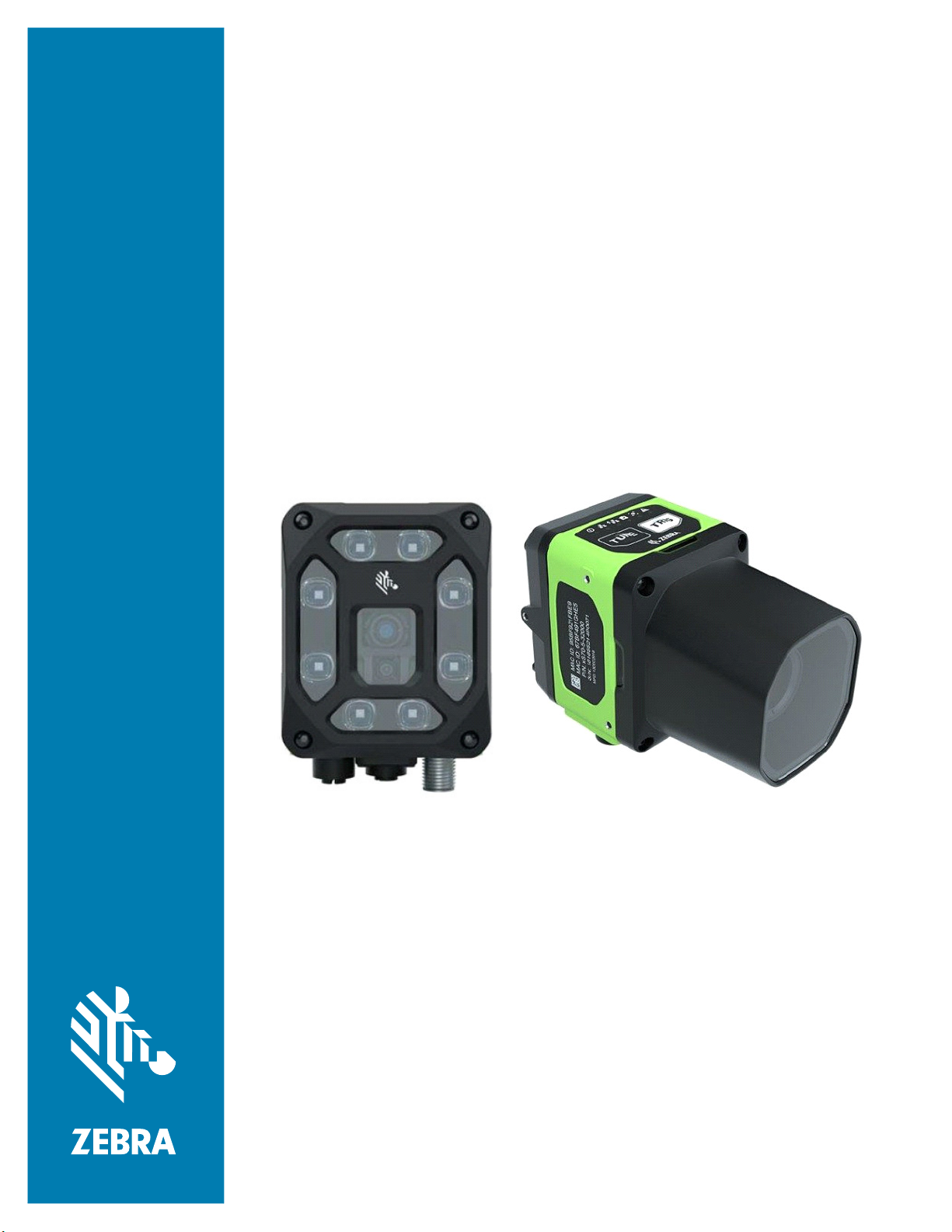
Table 3 External Lighting Accessories
Part Number Description
LGHT-B100RD-0000 LED Bar light, 100MM, red-625
wavelength, 5-Pin male M12 connector,
semi-diffused, includes transparent and
opaque diffusers
LGHT-B100BL-0000 LED Bar light, 100MM, blue-465
wavelength, 5-Pin male M12 connector,
semi-diffused, includes transparent and
opaque diffusers
LGHT-B100WH-0000 LED Bar light, 100MM, white wavelength,
5-Pin male M12 connector, semi-diffused,
includes transparent and opaque diffusers
LGHT-B100IR-0000 LED Bar light, 100MM, IR-850 wavelength,
5-Pin male M12 connector, semi-diffused,
includes transparent and opaque diffusers
LGHT-B300RD-0000 LED Bar light, 300MM, red-625
wavelength, 5-Pin male M12 connector,
semi-diffused, includes transparent and
opaque diffusers.
LGHT-B300BL-0000 LED Bar light, 300MM, blue-465
wavelength, 5-Pin male M12 connector,
semi-diffused, includes transparent and
opaque diffusers.
LGHT-B300WH-0000 LED Bar light, 300MM, white wavelength,
5-Pin male M12 connector, semi-diffused,
includes transparent and opaque diffusers.
LGHT-B300IR-0000 LED Bar light, 300MM, IR-850 wavelength,
5-Pin male M12 connector, semi-diffused,
includes transparent and opaque diffusers.
5

Getting Started
Table 3 External Lighting Accessories (Continued)
Part Number Description
Rings
LGHT-R100BL-0000 LED Ring light, 100MM, blue-465
wavelength, 5-Pin male M12 connector,
semi-diffused, includes transparent and
opaque diffusers.
LGHT-R100WH-0000 LED Ring light, 100MM, white wavelength,
5-Pin male M12 connector, semi-diffused,
includes transparent and opaque diffusers.
LGHT-R100IR-0000 LED Ring light, 100MM, IR-850
wavelength, 5-Pin male M12 connector,
semi-diffused, includes transparent and
opaque diffusers.
LGHT-R100RD-0000 LED Ring light, 100MM, red-625
wavelength, 5-Pin male M12 connector,
semi-diffused, includes transparent and
opaque diffusers.
Polarizers
LGHT-A100BP-0000 100MM Bar Light Polarizer
For use with 100mm External Light Bars
(LGHT-B100xx-0000).
Not for use with IR-850 wavelengths or
when IR image capture is required.
LGHT-A300BP-0000 300MM Bar Light Polarizer
For use with 300mm External Light Bars
(LGHT-B300xx-0000).
Not for use with IR-850 wavelengths or
when IR image capture is required.
LGHT-A100RP-0000 Light Polarizer
For use with 100mm External Ring Lights
(LGHT-R100xx-0000).
Not for use when IR image capture is
required.
6
Getting Started
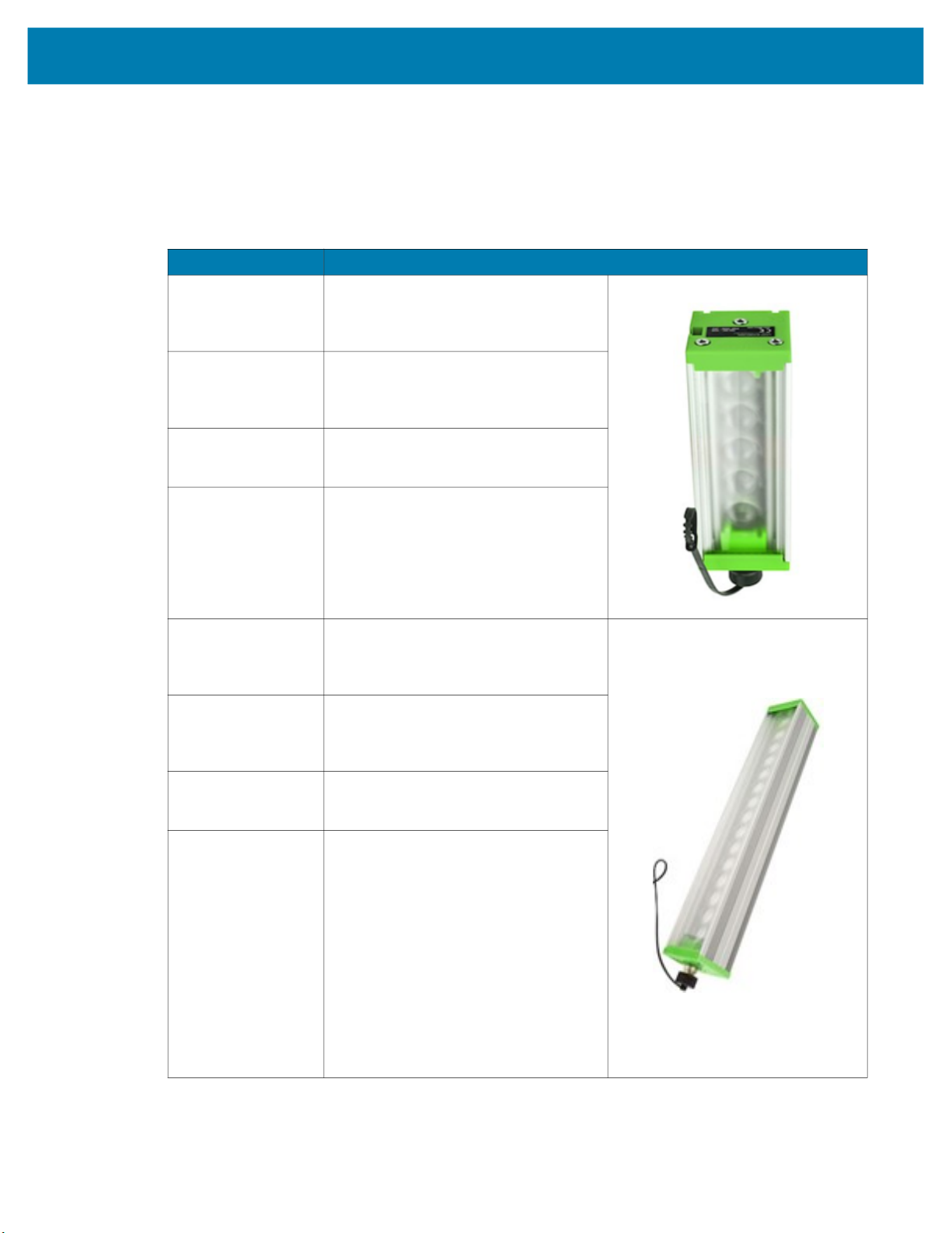
Internal Ring Lighting (xS40 Only)
Table 4 Internal Ring Lighting
Part Number Description
ZLED-XS40WH-0000 xS40 Internal Ring Light, White LED
For use with 100mm External Ring
Lights (LGHT-R100xx-0000).
Not for use when IR image capture
is required.
ZLED-XS40RD-0000 xS40 Internal Ring Light, Red LED
Red lighting is typically used to
capture images on paper.
ZLED-XS40IR-0000 FS40/VS40 Internal Ring Light, IR
LED
IR lighting is typically used in
environments where users do not
want to see any external lighting,
when detecting clear liquids, or
when inspecting produce.
ZLED-XS40MC-0000 FS40/VS40 Internal Ring Light,
Multi-Color - White, Red, Blue, IR
LED
White LEDs are controllable in
individual banks of 4 LEDs.
IR and Red are controllable in
individual banks of 2 LEDs.
7
Getting Started
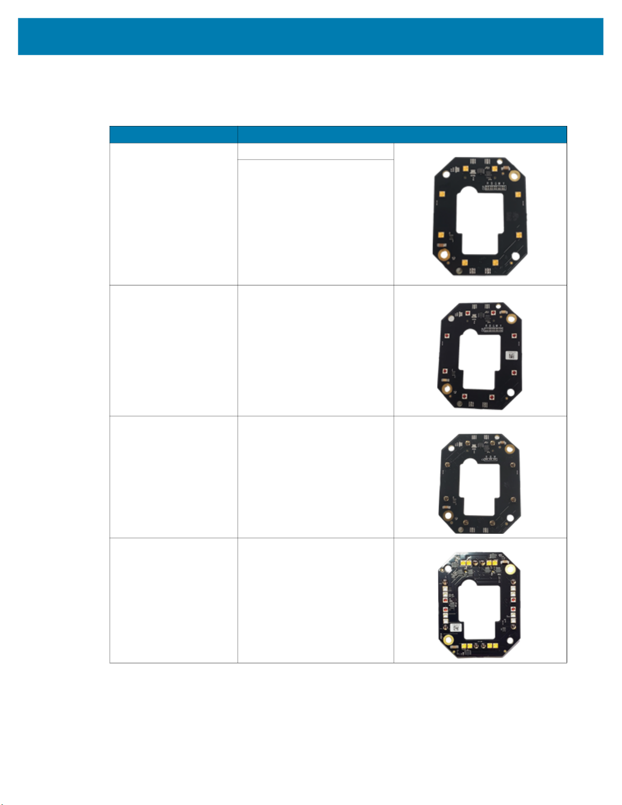
Table 4 Internal Ring Lighting
Part Number Description
Replacement Ring Light Covers
ZLED-XS40PW-0000 Integrated Light Cover
(Replacement) Cross Polarizer
For use with Wide Angle (WA) xS40
configurations only.
Not for use when IR image capture
is required.
ZLED-XS40PS-0000
ZLED-XS40CW-0000 Integrated Light Cover
ZLED-XS40CS-0000
Integrated Light Cover
(Replacement) Cross Polarizer
For use with Standard Range (SR)
xS40 configurations only.
Not for use when IR image capture
is required.
(Replacement)
For use with Wide Angle (WA) xS40
configurations only.
Integrated Light Cover
(Replacement)
For use with Standard Range (SR)
xS40 configurations only.
8
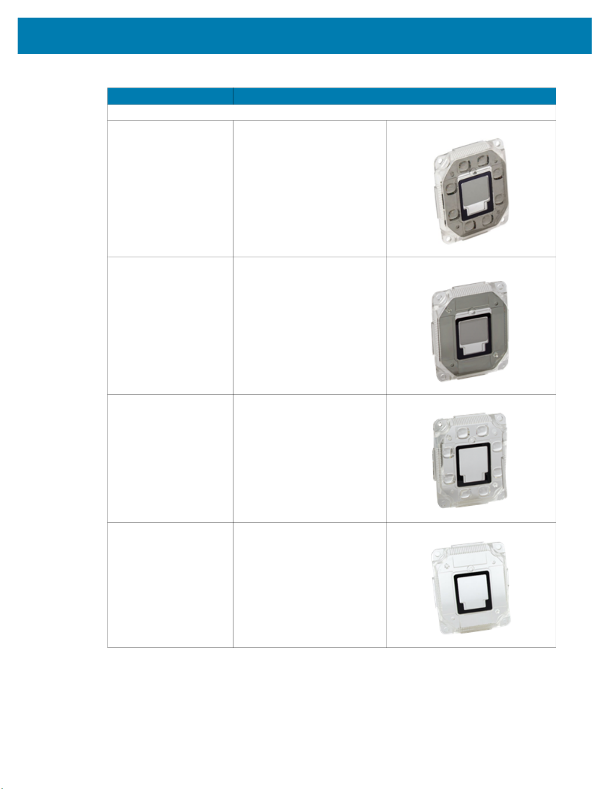
Internal and External Filters
Table 5 Internal and External Filters
Part Number Description Compatibility
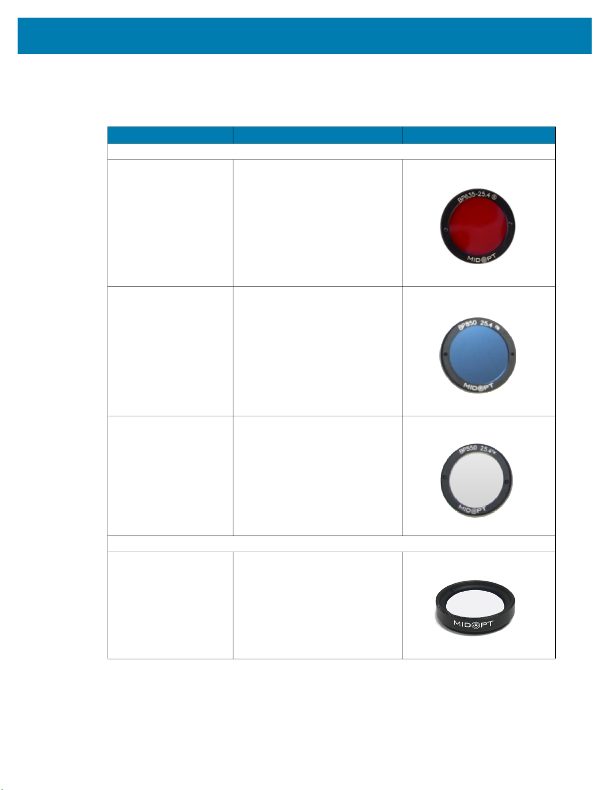
Internal Filters (In Between C-Mount Lens and Imager - xS70 Only)
FLTR-BP635-25400 Red Bandpass Filter, 635NM, 25.4MM
FLTR-BP850-25400 IR Bandpass Filter, 850NM, 25.4MM
Getting Started
For use between C-mount lens and
imager.
For use between C-mount lens and
imager
FLTR-BP550-25400 IR/UV Block Bandpass Filter, 550NM,
25.4MM
For use between C-mount lens and
imager.
External Filters (on the End of the C-Mount Lens - xS70 Only)
FLTR-BP550-25500 IR/UV Block B Filter, 550NM, 25.4MM
For use on the end of the C-mount lens.
9
Getting Started
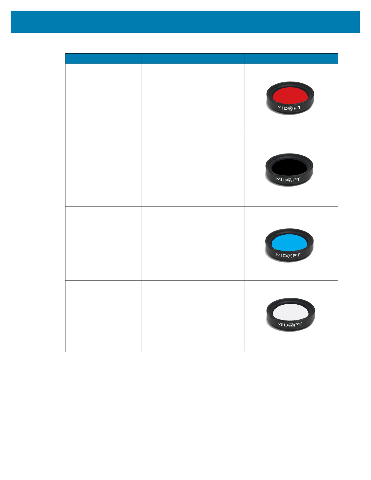
Table 5 Internal and External Filters
Part Number Description Compatibility
FLTR-BP635-25500 Red Bandpass Filter, 635NM, 25.4MM
For use on the end of the C-mount lens.
FLTR-BP850-25400 IR Bandpass Filter, 850NM, 25.4MM
For use on the end of the C-mount lens.
Not for use with IR lighting.
FLTR-BP470-25500 Blue Bandpass Filter, 470NM, 25.5MM
For use on the end of the C-mount lens.
FLTR-PZ120-25500 Ultra High Contrast Polarizer Filter,
25.4MM
For use on the end of the C-mount lens.
Not for use with IR lighting.
10
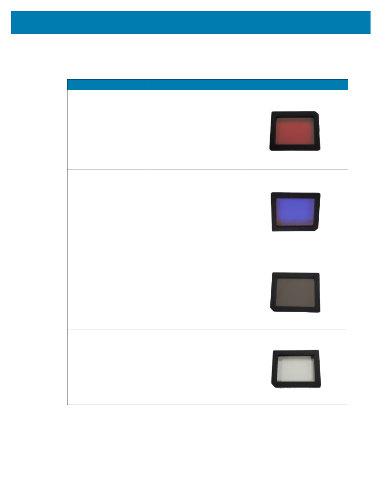
Internal Filters (xS40 Only)
Table 6 Internal Filters
Part Number Description
ZFLT-XS40RD-0000 Red Bandpass Zebra Filter
ZFLT-XS40BL-0000 Blue Bandpass Zebra Filter
Getting Started
ZFLT-XS40IR-0000 IR Bandpass Zebra Filter
ZFLT-XS40MC-0000 IR Blocker Zebra Filter
11
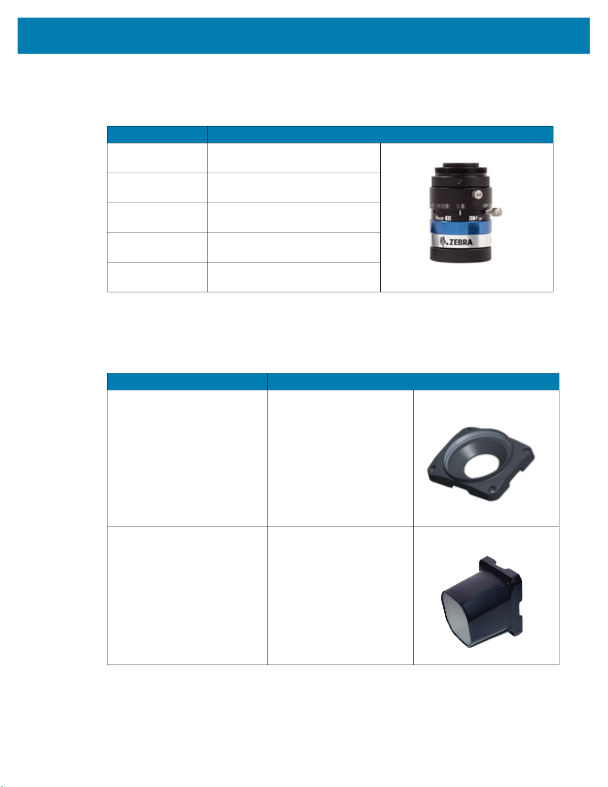
C-Mount Lenses (xS70 Only)
Table 7 External Lenses (xS70)
Part Number Description
LENS-M0800-0100 C-mount Lens
8MM focal length, 25.5 filter thread
LENS-M1200-0100 C-mount Lens
12MM focal length, 25.5 filter thread
LENS-M1600-0100 C-mount Lens
16MM focal length, 25.5 filter thread
LENS-M2500-0100 C-mount Lens
25MM focal length, 25.5 filter thread
LENS-M3500-0100 C-mount Lens
35MM focal length, 25.5 filter thread
Lens Covers (xS70 Only)
Getting Started
Table 8 xS70 Lens Covers
Part Number Description
LENS-XTC70-0000
LENS-XRC70-0000 Replacement IP67 Lens Cover
Threaded Lens Cover Adapter
12

Communication Cables
Table 9 Cables
Part Number Description Compatibility
USB Cables
CBL-USB02000-USC00 USB 2M, IP67 locking USB-C to USB C,
CBL-USB04000-USC00 USB 4M, IP67 locking USB-C to USB C
Getting Started
SuperSpeed
Compatible with all FS/VS devices.
Compatible with all FS/VS devices.
CBL-USB02000-USA00 USB 2M, IP67 locking USB-A to USB-C,
SuperSpeed
Compatible with all FS/VS devices.
CBL-USB04000-USA00 USB 4M, IP67 locking USB-A to USB C
Compatible with all FS/VS devices.
13
Getting Started
Table 9 Cables (Continued)
Part Number Description Compatibility
Ethernet Cables
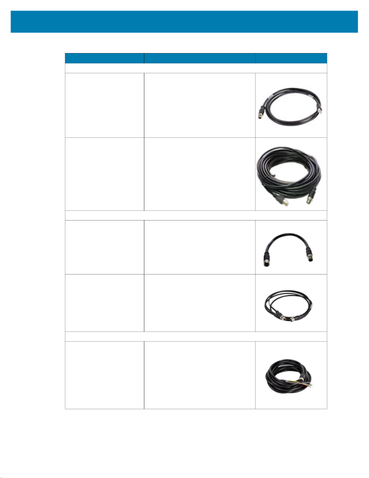
CBL-ENT05001-M1200 5M length, X-Coded M12 to RJ45
connectors
Compatible with all FS/VS devices that
include an Ethernet port.
CBL-ENT15001-M1201 15M length, X-Coded M12 to RJ45
connectors
Compatible with all FS/VS devices that
include an Ethernet port.
External Light Control Cables
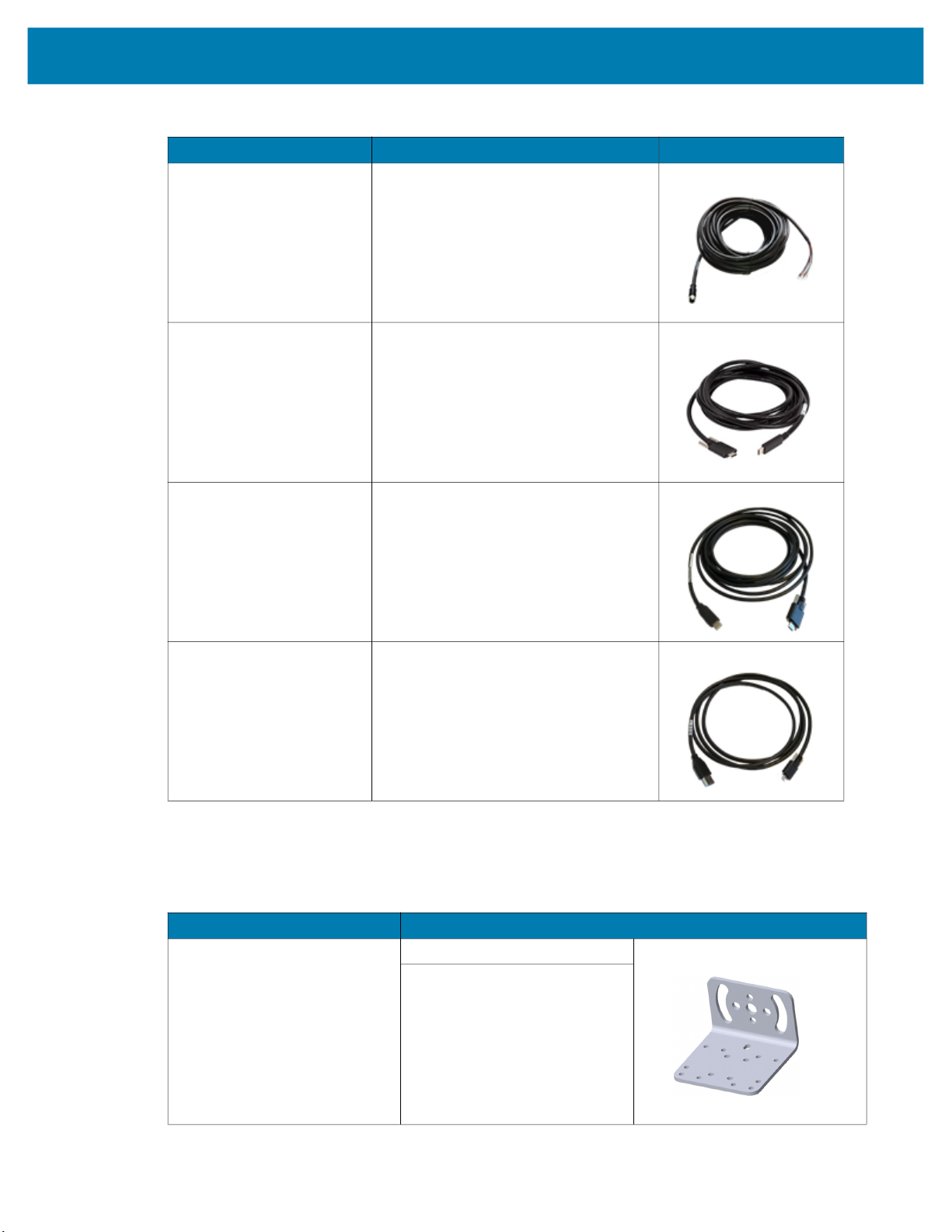
CBL-LGT00000-M1200 5-pin M12 to 5-pin M12 External Light
Control C, 0.3M length
Only compatible with xS40 and xS70
devices that include an external light port.
CBL-LGT00201-M1200 5-pin M12 to 5-pin M12 External Light
Control C, 2M length
Only compatible with xS40 and xS70
devices that include an external light port.
Power Cables
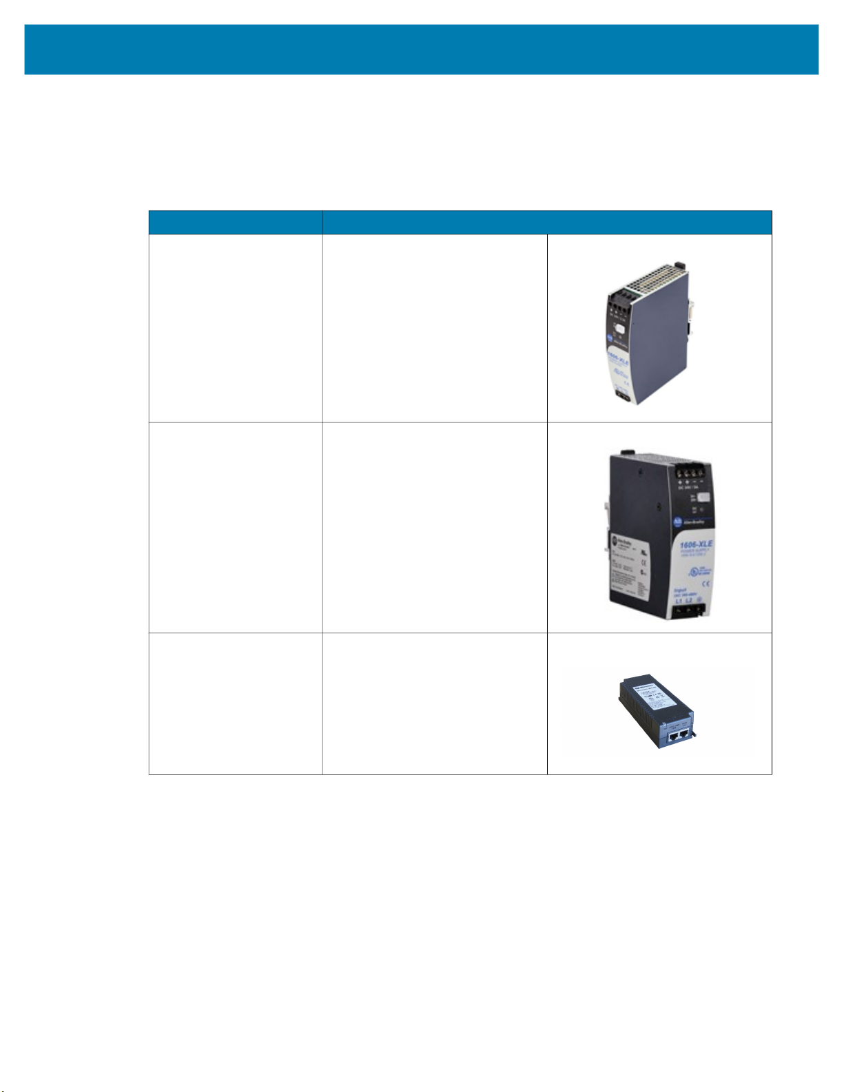
CBL-PWR05001-M1200 12-pin M12 to flying lead breakout cable
Compatible with all FS/VS devices.
14
Getting Started
Table 9 Cables (Continued)
Part Number Description Compatibility
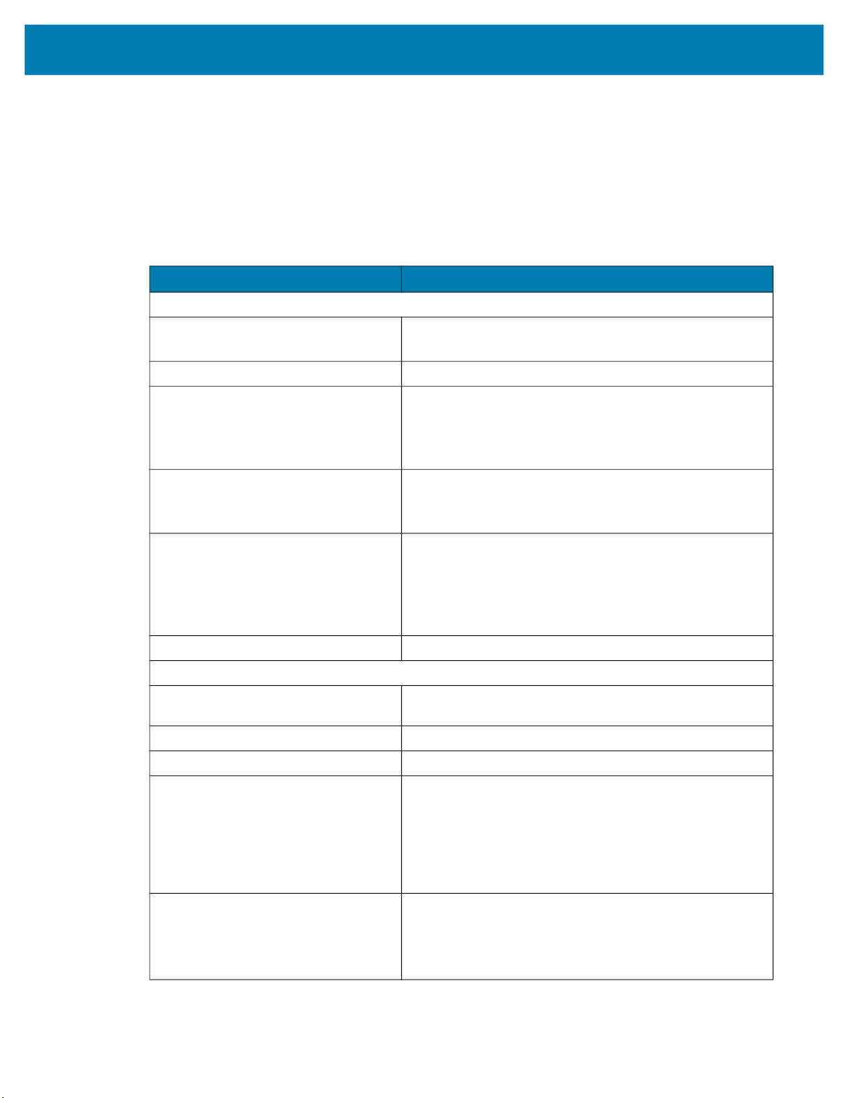
CBL-PWR15001-M1200 12-pin M12 to flying lead breakout cable
Compatible with all FS/VS devices.
CBL-USB00200-USC00 USB-C Cable, 4M length
Compatible with all FS/VS devices.
CBL-USB00400-USC00 USB-A Cable, 2M length
Compatible with all FS/VS devices.
Brackets
CBL-USB00200-USA00 USB-A Cable, 4M length
Compatible with all FS/VS devices.
Table 10 L-Mount Bracket
Part Number Description
BRKT-LMNT-U000
L-Mount Bracket
For use with Wide Angle (WA)
xS40 configurations only.
See
Mounting the Device Using
the L-Bracket Accessory
(BRKT-LMNT-U000) on
page 32
for mounting instructions.
15
Power Supplies
Table 11 Power Supplies
Part Number Description
PWR-24V03A-0000 Power Supply, 24VDC 3.3AMP, DIN
PWR-24V05A-0000 Power Supply, 24VDC 5AMP, DIN
Getting Started
Rail Mount
Rail Mount
PWR-POE30W-0000 Power over Ethernet Injector, 30W
POE+, AC Input
16
Getting Started
FS/VS Smart Camera Specifications
The tables below describe the design, performance, environment and regulatory characteristics of the
FS/VS Smart Camera series.
xS40 Specifications
Table 12 xS40 Specifications
Item Description
Physical Characteristics
Dimensions 2.1 in. H x 2.5 in. W x 3.6 in. D
54.0 mm H x 64.0 mm W x 91.4 mm D
Weight 14.1 oz./400.0 g
Power 10 to 30 VDC external power supply, 36W max at 24V
• Class 4 PoE+ source, 25.5W max
• Class 3 PoE source, 13W max
• USB Type-C host, 7.5W max at 5V 1.5A or 15W max at 5V 3.0A
Configurable IO (4) Four opto-isolated GPIO: GPIO0,1,2,3
(5) Five non-isolated GPIO: GPIO4,5,6*,7*,8*
*Unavailable when External Light Mode is enabled
Interface Ports (1) M12 X-Coded 1000/100/10 Mbps Ethernet
(1) M12 12-pin Power/GPIO
(1) M12 5-pin External Light Power & Control/GPIO
(1) USB 3.0 SuperSpeed Type-C with DisplayPort
Alt Mode is Available with one or two Ethernet ports
Communication Protocols Ethernet/IP, PROFINET, CC-Link, Modbus TCP, TCP/IP
Performance Characteristics
Image Sensor Monochrome: 2.3 MP (1920 x 1200 pixels) CMOS
Sensor with Global Shutter and 3.0 um Pixel Size
Acquisition Rate Up to 60 frames/second
Aimer Red Class II Laser; 8-point sunburst pattern
Illumination Field replaceable modules:
• (8) 660nm Red LEDs
• (8) 850nm IR LEDs
• (8) 2700K (Color Temperature) White LEDs
• (4) 660nm Red LEDs + (8) 850nm IR LEDs + (8) 2700K (Color
Temperature) White LEDs
Imager Field of View
SR (Standard Range): 10.8mm Liquid Lens
(30° H x 19° V Nominal)
WA (Wide Angle): 6.8mm Liquid Lens
(46° H x 29° V Nominal)
17

Table 12 xS40 Specifications
Item Description
User Environment
Getting Started
Operating Temperature
Storage Temperature -40°F to 113°F / -40° to 70°C
Vibration Resistance EN 60068-2-6, 14 mm @ 2 to 10 Hz, 1.5 mm @ 13 to 55
Shock Resistance EN 60068-2-27, 30g; 11 ms; 3 shocks on each axis
Environmental Sealing IP65 & IP67
Humidity 5% to 90% RH (Non Condensing)
Light Immunity Product must operate in: Incandescent 450 ft candles, Sunlight
Electrostatic Discharge ±15 kV Air, ±8 kV Contact, ±8 kV Indirect
Trigger Durability Withstand 1,000 cycles of operation with no degradation in
Regulatory
Environmental EN 50581:2012
Electrical Safety IEC 62368-1 (Ed.2)
32° F to 113° F/0° C to 45° C (10-30VDC external power supply,
duty cycle-dependent)
32° F to 104° F/0° C to 40° C (POE, duty cycle dependent)
Hz; 2 g @ 70 to 500 Hz; 2 hours on each axis
<6000 ft candles, Florescent 450 ft candles, Mercury Vapor 450
ft candles, Sodium Vapor 450 ft candles, LED 450 ft candles
functionality
EN IEC 63000:2018
EN 62368-1:2014/A11:2017
Laser Safety (xS40 Only) 21CFR1040.10 & 21CFR1040.11
IEC/EN 60825-1:2014 (Ed.3)
LED Safety IEC 62471: 2006 (Ed.1)
EN 62471: 2008
EMI/EMS EN 55032:2015/A11: 2020
EN 55035:2017/A11: 2020
EN 61000-3-2: 2014
EN 61000-3-3: 2013
EN 61000-6-2: 2005,2019
FCC 47 CFR Part 15, Subpart B
ICES-003, Issue 7
EU Declaration of Conformity 2014/30/EU; 2014/35/EU; 2011/65/EU.
Refer to the Declaration of Conformity (DoC) for details of
compliance to the current standards. The DoC is available at:
zebra.com/doc
18

xS70 Specifications
NOTE: The xS70 is only to be used with the metal assembly in order to pass the ESD safe
specification.
Table 13 xS70 Environmental Specifications
Physical Characteristics
Dimensions 2.5 in. H x 2.5 in. W x 3.75 in. D
Weight 22.9 oz./650.0 g
Power 10 to 30 VDC external power supply, 36W max at 24V
Configurable IO (4) Four opto-isolated GPIO: GPIO0,1,2,3
Getting Started
Item Description
63.0 mm H x 64.0 mm W x 95.0 mm D
• Class 4 PoE+ source, 25.5W max
• Class 3 PoE source, 13W max
• USB Type-C host, 7.5W max at 5V 1.5A or 15W max at 5V 3.0A
(5) Five non-isolated GPIO: GPIO4,5,6*,7*,8*
*Unavailable when External Light Mode is enabled
Interface Ports (2) M12 X-Coded 1000/100/10 Mbps Ethernet*
(1) M12 12-pin Power/GPIO/RS-232
(1) M12 5-pin External Light Power & Control/GPIO
(1) USB 3.0 SuperSpeed Type-C with DisplayPort Alt Mode
*Available with one or two Ethernet ports, PoE is only supported
by the primary Ethernet port
Communication Protocols Ethernet/IP, PROFINET, CC-Link, Modbus TCP, TCP/IP
Performance Characteristics
Image Sensor Monochrome: 2.3 MP (1920 x 1200 pixels) CMOS
Sensor with Global Shutter and 3.0 um pixel size
Acquisition Rate 60 frames/second
Illumination Supports many standard external illumination systems while
powered by 24 VDC supply
Imager Field of View Flexible; dependent upon C-mount lens selection
User Environment
Operating Temperature 32° F to 113° F/0° C to 45° C (10-30VDC external power supply,
duty cycle-dependent)
32° F to 104° F/0° C to 40° C (POE, duty cycle-dependent)
Storage Temperature -40° F to 158° F/-40° C to 70° C
Vibration Resistance EN 60068-2-6, 14 mm @ 2 to 10 Hz, 1.5 mm at 13 to 55 Hz; 2 g
at 70 to 500 Hz; 2 hours on each axis
Shock Resistance EN 60068-2-27, 30 g; 11 ms; 3 shocks on each axis
Environmental Sealing IP65 and IP67
Humidity 5% to 90% RH, non-condensing
19
Getting Started
Table 13 xS70 Environmental Specifications (Continued)
Item Description
Light Immunity Product must operate in: Incandescent 450 ft candles, Sunlight
<6000 ft candles, Florescent 450 ft candles, Mercury Vapor 450
ft candles, Sodium Vapor 450 ft candles, LED 450 ft candles
Electrostatic Discharge ±15 kV Air, ±8 kV Contact, ±8 kV Indirect
Trigger Durability Withstand 1,000 cycles of operation with no degradation in
functionality
Regulatory
Environmental EN 50581:2012; EN IEC 63000:2018
Electrical Safety IEC 62368-1 (Ed.2); EN 62368-1:2014/A11:2017
EMI/EMS EN 55032:2015/A11: 2020
EN 55035:2017/A11: 2020
EN 61000-3-2: 2014
EN 61000-3-3: 2013
EN 61000-6-2: 2005,2019
FCC 47 CFR Part 15, Subpart B
ICES-003, Issue 7
EU Declaration of Conformity 2014/30/EU; 2014/35/EU; 2011/65/EU.
Refer to the Declaration of Conformity (DoC) for details of
compliance to the current standards. The DoC is available at:
zebra.com/doc
20

Installation
This section describes the steps to mount the FS/VS Smart Camera with an L-bracket and install an
illumination system into the xS40 or a C-mount lens onto the xS70.
Dimensional Drawings
The dimensional drawings below illustrate the mounting patterns supported by the FS/VS Smart Camera.
For additional information on mounting the device with the L-bracket accessory, see Mounting the Device
Using the L-Bracket Accessory (BRKT-LMNT-U000) on page 32.
xS40 Dimensional Drawings
Figure 1 xS40 Side Dimensions
59.25
2X M3 X 0.50 THD
X DEPTH 4.5 MM MAX
29.00
29.23
25.00
12 PIN M12 CONN
38.70
Optical Axis
2X M3 X 0.50 THD
X DEPTH 4.5 MM MAX
Optical Axis
29.23
19.63
5 PIN M12 CONN
25.00
8 PIN M12 CONN
32.75
USB C CONN
38.70
54.00
59.25
91.40
29.00
21
 Loading...