

Zebra VS40 Industrial Machine Vision FS/VS Smart Camera Series Industrial Ethernet User Guide

FS/VS Smart
Camera Series
Industrial Ethernet Guide
MN-003811-01EN Rev A

ZEBRA and the stylized Zebra head are trademarks of Zebra Technologies Corporation, registered in
many jurisdictions worldwide. All other trademarks are the property of their respective owners. ©2021
Zebra Technologies Corporation and/or its affiliates. All rights reserved.
Information in this document is subject to change without notice. The software described in this document
is furnished under a license agreement or nondisclosure agreement. The software may be used or copied
only in accordance with the terms of those agreements.
For further information regarding legal and proprietary statements, please go to:
SOFTWARE:zebra.com/linkoslegal
COPYRIGHTS:zebra.com/copyright
WARRANTY:zebra.com/warranty
END USER LICENSE AGREEMENT: zebra.com/eula
Terms of Use
Proprietary Statement
This manual contains proprietary information of Zebra Technologies Corporation and its subsidiaries
(“Zebra Technologies”). It is intended solely for the information and use of parties operating and
maintaining the equipment described herein. Such proprietary information may not be used, reproduced,
or disclosed to any other parties for any other purpose without the express, written permission of Zebra
Technologies.
Product Improvements
Continuous improvement of products is a policy of Zebra Technologies. All specifications and designs are
subject to change without notice.
Liability Disclaimer
Zebra Technologies takes steps to ensure that its published Engineering specifications and manuals are
correct; however, errors do occur. Zebra Technologies reserves the right to correct any such errors and
disclaims liability resulting therefrom.
Limitation of Liability
In no event shall Zebra Technologies or anyone else involved in the creation, production, or delivery of the
accompanying product (including hardware and software) be liable for any damages whatsoever
(including, without limitation, consequential damages including loss of business profits, business
interruption, or loss of business information) arising out of the use of, the results of use of, or inability to
use such product, even if Zebra Technologies has been advised of the possibility of such damages. Some
jurisdictions do not allow the exclusion or limitation of incidental or consequential damages, so the above
limitation or exclusion may not apply to you.
2

Revision History
Revision Description
MN-003811-01 Rev. A 6/21 Initial Rev A. Release
3

Contents
Terms of Use ......................................................................................................................... 2
Proprietary Statement ......................................................................................................... 2
Product Improvements ........................................................................................................ 2
Liability Disclaimer .............................................................................................................. 2
Limitation of Liability ............................................................................................................ 2
Revision History .................................................................................................................... 3
About This Guide
Service Information ............................................................................................................... 7
Initial Setup
Hardware/Software Prerequisites ......................................................................................... 8
Activating Industrial Ethernet ................................................................................................ 9
Configuring Industrial Ethernet Input & Output ................................................................... 10
User Control Data ............................................................................................................. 10
Results Data ..................................................................................................................... 11
Industrial Ethernet Interface
Job Control/Status ............................................................................................................... 12
Trigger Control/Status ......................................................................................................... 14
Results Control/Status ........................................................................................................ 15
User Data Control/Status .................................................................................................... 16
Error Codes Control/Status ................................................................................................. 16
User Control and Data Structure ......................................................................................... 17
User Data Format for Raw Mode (Mode = 1) ................................................................... 17
User Data Format for Entry Mode (Mode = 0) .................................................................. 18
Results Status and Data Structure ...................................................................................... 18
Results Data Format Raw Mode (Mode = 1) .................................................................... 19
Results Data Format for Entry Mode (Mode = 0) .............................................................. 19
Entry Type List .................................................................................................................... 20
Fixed Scanning Barcode Results Structure ........................................................................ 20
Pattern Match Results Structure ......................................................................................... 21
4

EtherNet/IP
Contents
Electric Data Sheet (EDS) File ............................................................................................ 22
TCP/IP Interface Object ...................................................................................................... 22
I/O Assemblies .................................................................................................................. 22
Status and Results Assembly (Device to PLC) ........................................................... 22
I/O Connections ................................................................................................................ 23
Exclusive Owner Connection ...................................................................................... 23
Configuring Rockwell ControlLogix Communication ........................................................... 24
Register the FS/VS EDS File ............................................................................................ 24
Method One: Download from the Device ............................................................................ 24
Method Two: Manually Install from the Developer Zip File ......................................... 24
Adding the FS/VS Smart Camera to the I/O Configuration ............................................... 25
FS/VS Smart Camera I/O Tags ........................................................................................... 26
Status and Results Input Assembly .................................................................................... 27
Job Control and Setup Assembly ........................................................................................ 28
Fixed Scanner Add-On Instruction (AOI) ............................................................................ 29
Creating a New Project that Uses AOI_FixedScanner ...................................................... 29
Using the Fixed Scanner Add-On Instruction ...................................................................... 35
PROFINET Interface
GSDML File ......................................................................................................................... 36
PROFINET IO Modules ....................................................................................................... 36
Command IO Module ........................................................................................................ 36
CommandData32 IO Module ............................................................................................ 37
CommandData64 IO Module ............................................................................................ 37
CommandData128 IO Module .......................................................................................... 37
Response IO Module ........................................................................................................ 38
ResponseData32 IO Module ............................................................................................. 39
ResponseData64 IO Module ............................................................................................. 39
ResponseData128 IO Module ........................................................................................... 39
Configuring Siemens S7 Communications .......................................................................... 40
Register the GSDML File .................................................................................................. 40
Finding the Device and Configuring the Device Name ..................................................... 40
Adding the FS/VS Smart Camera to the I/O Configuration ................................................. 42
Fixed Scanner Function Block (FB) .................................................................................... 44
Creating a Project that uses FB_FixedScanner ................................................................ 44
Using the Fixed Scanner Function Block .......................................................................... 48
Modbus TCP Interface
Modbus Register Locations ................................................................................................. 49
Command Registers Mapping ............................................................................................. 50
Command Data Registers Mapping .................................................................................... 50
Response Register Mapping ............................................................................................... 50
Response Data Registers Mapping .................................................................................... 51
Typical Use Case for Triggering a Job ................................................................................ 52
5

Error Codes
Contents
6

About This Guide
The FS/VS Smart Camera Industrial Ethernet Guide provides instructions for setting up and programming
the device for Industrial Ethernet applications.
IMPORTANT: If you have a problem with your equipment, contact Zebra Global Customer Support for your
region. Contact information is available at: zebra.com/support
Service Information
If you have a problem with your equipment, contact Zebra Global Customer Support for your region.
Contact information is available at: zebra.com/support
When contacting support, please have the following information available:
• Serial number of the unit
• Model number or product name
• Software type and version number.
.
Zebra responds to calls by email, telephone or fax within the time limits set forth in support agreements.
If your problem cannot be solved by Zebra Customer Support, you may need to return your equipment for
servicing and will be given specific directions. Zebra is not responsible for any damages incurred during
shipment if the approved shipping container is not used. Shipping the units improperly can possibly void
the warranty.
If you purchased your Zebra business product from a Zebra business partner, contact that business
partner for support.
7

Initial Setup
Refer to the FS/VS Smart Camera Product Reference Guide for detailed information on:
• Connection Diagrams, including how to power the device.
• Status Indicators (LED and Beeper) and their meanings.
• Default Factory Settings, including how to restore Factory Settings.
• Ethernet Setup, including how to discover a device and set an IP address.
• Firmware update methods.
• Building and deploying Jobs, including configuration of Trigger modes.
• Accessing the Web HMI
• Licensing and Security
Hardware/Software Prerequisites
The following list of components is required for initial setup, testing, and development of Industrial Ethernet
applications that use the FS/VS Smart Camera.
• An FS/VS Smart Camera with Ethernet support that is configured to the correct Industrial Ethernet
Protocol and IP address. The device should be configured with the Jobs required to perform the work
needed by the Industrial Ethernet application.
• An M12 X-Coded cable that can connect the FS/VS Smart Camera Ethernet port to your network.
• The appropriate cabling and power supply necessary to power the FS/VS Smart Camera.
• A PC running Windows 7 or higher (Windows 10 recommended) to view the Web HMI, Zebra’s Aurora
Application, and development software for PLC applications.
• An Ethernet switch or router (if not connecting FS/VS Smart Camera directly to a PLC).
• An Industrial Ethernet PLC (Programmable Logic Controller) that supports one of the supported protocols
(EtherNet/IP, PROFINET, or Modbus TCP) and an Ethernet switch or router (if not connecting the device
directly to a PLC).
NOTE: Industrial Ethernet testing has been performed with the following PLCs and software:
Rockwell Compact Logix 5069-L306ER and Logix Studio 5000 v32.02.00 Software
Siemens S7 1500/1200 PLC and Totally Integrated Automation (TIA) v15.1 Software.
• FS/VS Smart Camera Industrial Ethernet Developer Files (CAAFSS00-001-Rxx.zip)
8
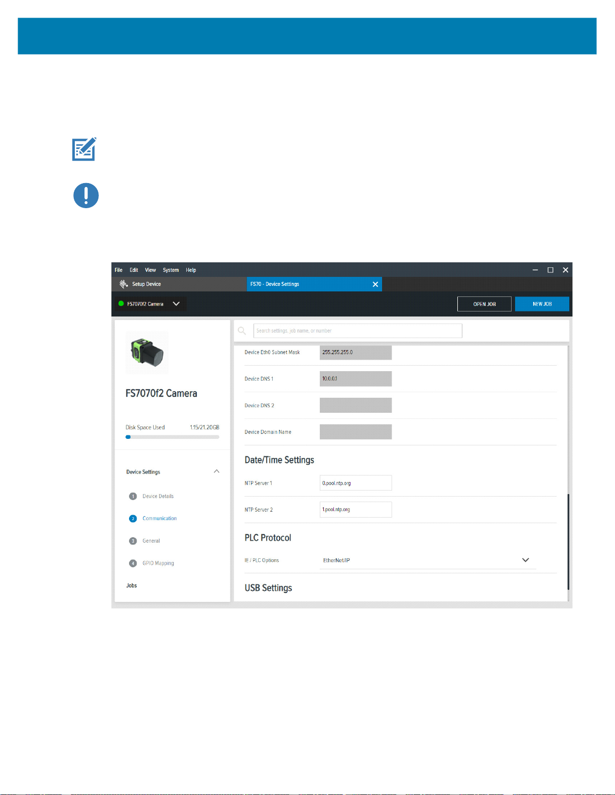
Activating Industrial Ethernet
The Zebra Aurora Application device settings provide an option to select which PLC protocol can be
enabled on the device, as shown in the PLC Protocol selection in the figure below.
IMPORTANT: It is required that on any PLC Protocol change, the device must be rebooted for the
change to go into effect.
IMPORTANT: After enabling PROFINET protocol support, the FS/VS Smart Camera is only
accessible on the network through the PROFINET protocol. It is recommended that after enabling the
protocol you use the TIA Portal to find all the accessible devices and set the PROFINET device name
of the FS/VS Smart Camera.
Figure 1 PLC Protocol
Initial Setup
9
Initial Setup
Configuring Industrial Ethernet Input & Output
Users can specify what results and configuration is provided to the PLC through the Zebra Aurora
applications Connect workflow. When Connect is selected, click the Industrial Ethernet list item on the
left of the application.
Figure 2 Connect
NOTE: The updated Job must be deployed and set as active on the device for any changes to be seen
from the PLC.
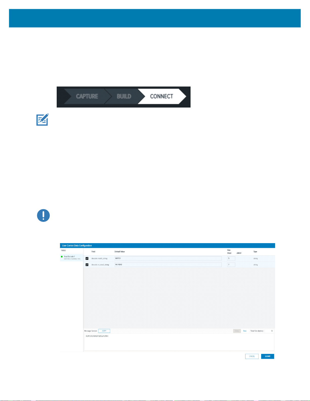
User Control Data
The User Control Data user interface allows for the PLC to make runtime changes to Job input parameters,
such as Barcode Match Strings or No Read strings.
Click the Add or Edit button to display the User Control Data Configuration dialog and the possible input
parameters. Check the specific input parameter to be changed from the PLC and configure the default
value and the size. Refer to the Message Sample window for a view of what the data must look like when
sent from the PLC to the device. For User Control Data, it is recommended that Raw Mode is selected.
This removes the need to set the proper Entry header for Entry mode. When the form is complete, click the
Submit button. From the main window, reorder the input parameters using a drag and drop technique.
IMPORTANT: Default value changes do not affect the job, they are used for Message Sample preview
only.
Figure 3 User Control Data Configuration
10
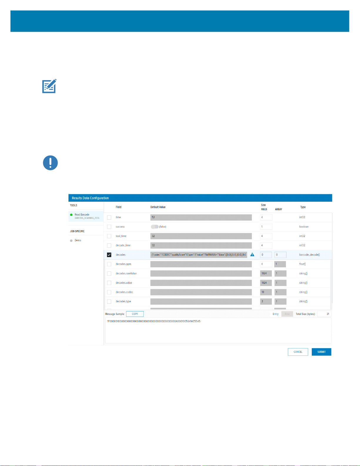
Results Data
The Results Data user interface allows for the user to control which results are sent to the PLC upon Job
completion.
NOTE: The default barcode job on the FS/VS device is configured to provide the FS Barcode
Structure to the PLC. Also, new FS Jobs have FS Barcode Structure automatically configured as the
result output to the PLC.
Click the Add (or Edit) button to display the Results Data Configuration Dialog and the possible tools and
output parameters that can be added to the Result Data. Check the result parameter you intend to receive
from the FS/VS Smart Camera when a Job completes. Refer to the Message Sample window for a view of
what the data looks like when sent to the PLC. Entry or Raw mode can be selected, for more information
on these modes refer to the Results Status and Data Structure on page 18. Once complete, click the
Submit button. From the main window, reorder the result data items using a drag and drop technique.
IMPORTANT: Default value changes do not affect the job, they are used for Message Sample preview
only.
Figure 4 Results Data Configuration
Initial Setup
11

Industrial Ethernet Interface
All Industrial Ethernet protocols supported by the FS/VS Smart Camera use the interface described in this
chapter. Review this section before proceeding to the specific Industrial Ethernet protocol section relevant
to your use case.
Job Control/Status
The FS/VS Smart Camera runs scripts, also known as Jobs, to decode barcodes and solve machine vision
problems. This section includes information on Job Control and Status features available to the PLC
programmer.
Table 1 Job Control/Status Features
Name Direction
Job
Control
Reset
Counters
Job Slot
Control
Job Slot
Number
PLC to Device 1 Job Control sets the state of the Job. When set to 0, the Job is
PLC to Device 1 When this bit is toggled from 0 to 1, all Job counters are reset.
PLC to Device 1 Job Slot Control is used in conjunction with the Job Control bit.
PLC to Device 2 This number field is used in conjunction with the Job Slot
Size
(Bits)
Description
inactive (stopped, for example, no Job loaded or not active).
When the value is set to 1 while the Job Slot Control bit is 0, the
default (or last active) Job will be loaded and set to the loaded
or active state. If the Job Slot Control bit is 1, the Job specified
by the Job Slot Number is loaded and set to the Loaded or
Active state.
If a Job load fails, an error code will be provided as specified in
Error Codes section.
the
As a result, the Job sequence number will be reset to 1 and any
remaining results in the Result Queue will be cleared.
When this bit is set to 1 and the Job Control bit is toggled from 0
to 1, a Job slot switch occurs. The Job that is loaded and made
active is then specified in the Job Slot Number field.
Control bit and the Job Control bit. When the Job Slot Control
bit is set and the Job Control bit is toggled from 0 to 1, this
number will indicate the Job that will be Loaded and made
active. If the number is 0, the Job will be unloaded (made
inactive).
12

Industrial Ethernet Interface
Table 1 Job Control/Status Features (Continued)
Name Direction
Job Status Device to PLC 1 Job Status indicates whether a Job is in the loaded or active
Active Job
Slot
Number
Results
Job Slot
Number
Job Pass Device to PLC 1 This bit is set to 1 if the Job results pass, or set to 0 if the Job
Job Fail Device to PLC This bit is set to 1 if the Job results fail, or set to 0 if the Job
Echo
Register
Control
Echo
Register
Status
Device to PLC 16 The Active Job Slot Number represents the Current Job Slot.
Device to PLC 16 The Results Job Slot Number represents the Results Job Slot.
PLC to Device 16 This 16-bit value is reflected in the PLC based on the value that
Device to PLC 16 This 16-bit value matches the value that the PLC writes to its
Size
(Bits)
Description
state or in the Unloaded Stopped state. Depending on the Jobs
trigger type, a Loaded Job may either be Running or Idle
(waiting on trigger).
0 = Stopped/Unloaded, 1 = Active/Loaded.
Under normal conditions (non-error conditions) this bit matches
the Job Control bit.
This 16-bit integer corresponds to the Job slot of the currently
Loaded or Active Job.
This 16-bit integer corresponds to the Job slot of the Job that
was run to produce the results in the Results data section.
results fail.
results pass.
Some error conditions may not be considered to be a fail, refer
Error Codes section for additional information.
to the
the PLC writes to it. This field allows the PLC programmers to
verify that the output assembly has been written to the camera
when this value matches the written value.
Echo Register Control. This field allows the PLC programmers
to verify that the output assembly has been written to the
camera when this value matches the written value.
13

Trigger Control/Status
Each Job will have one of the following trigger modes:
• Single Shot
• Continuous
• Presentation
• Burst
• Level
Depending on the Trigger Mode, the action that the device takes when an external Trigger is initiated may
differ. For example, when a Job is set for Single Shot, a PLC/GPIO Trigger initiates a single run of that Job.
However, if the Job is set to Continuous, a PLC/GPIO Trigger may produce no change in behavior. Refer
to the Trigger Modes Configuration section in the FS/VS Smart Camera Series Product Reference Guide
for additional information.
The following table describes the control and status of Trigger functionality as it relates to Industrial
Ethernet.
Table 2 Trigger Modes
Industrial Ethernet Interface
Name Direction
Trigger Enable
Control
Trigger PLC to Device 1
PLC to Device 1 Set to 1 to enable triggering
Size
(Bits)
Description
Set to 0 to ignore trigger
When changed from 0 to 1, the current Job begins
running or processing. This bit is only acted upon when
the following conditions are met:
• Job Status is 1 (Job is loaded/active)
• Trigger Ready is 1 (Device is ready to accept
triggers)
Trigger Ready Device to PLC 1 Indicates when the device is ready to accept a new
trigger. This bit is set to 1 when Trigger Enable Control
is 1 and the active Job Slot is not 0. If the bit is set to 0,
the triggers will be ignored.
Trigger Status Device to PLC 1 This bit is set to 1 when the Job is currently executing or
running. This bit is cleared when the Job is stopped or
idle.
14

Results Control/Status
Job results are made available upon completion of the Job. The result data is dependent upon the type of
Job that is run and the Job that was configured. If multiple results are made available before the PLC can
process them, it is suggested that Results Buffering is enabled to ensure that no results are lost.
Table 3 Results Data
Industrial Ethernet Interface
Name Direction
Results Buffer
Control
Results Ack PLC to Device 1 This bit is only applicable when Results Available is set to
Results
Available
Results Buffer
Overflow
Results Queue
Count
Result Data Device to PLC Array of
Results Packet
Sequence
PLC to Device 1 Results Buffer Control enables the queuing of result data
Device to PLC 1 Indicates that a new set of read results are available. This
Device to PLC 1 Indicates that the device has discarded a set of read results
Device to PLC 8 Results Queue Count records the number of results
PLC to Device 16 This number is used in conjunction with Results Ack. It is
Size
(Bits)
Bytes
Description
(queue size is set to 32). If set to 1, new results are queued
on the device and remain present until acknowledged. To
retrieve the next set of results from the queue on the
Results Ack, the bit must transition from 0 to 1. The device
responds to this acknowledgment by clearing the Results
Available bit when no more results are queued on the
device. See the Results Queue Count row in this table for
more information on how results are queued on the device.
If results buffering is not enabled (set to 0), newly received
read results overwrite the content of the Result Data in the
Response/Status section of the Input Assembly.
The Results Overflow bit is set when this bit is set and there
is no more space in the queue to accept a new result.
1. When this bit transitions from 0 to 1, the PLC is then sent
the next set of results. If there are no additional results
queued on the device, the Results Available bit is cleared.
bit is cleared when the results are acknowledged.
because the results queue is full. This is cleared when the
next set of results are successfully queued.
currently in the queue on the device. This bit is set to 0 if
there are no results in the queue.
Results Status and Data Structure on page 18 for
See
more information on contents of the Results Data Structure.
expected to be changed before Results Ack is set to ensure
that Result Ack is not missed by the device.
15

User Data Control/Status
A PLC program can modify Job input parameters at runtime through User Data Control. Updating Job input
parameters are not permanent and are reset to the Job defaults if the Job is reloaded.
Table 4 User Data
Name Direction Size (Bits) Description
User Data
Control
User Data
Status
User Data PLC to
PLC to
Device
Device to
PLC
Device
Industrial Ethernet Interface
1 When this bit is toggled from 0 to 1, the current Job’s
User Data will be overwritten with data provided by the
PLC. See the User Data Status bit description to know
when the User Data has taken affect. When this bit is
cleared, the User Data Status bit will also be cleared.
1 When set to 1, this bit indicates that the new User Data
has taken affect. This bit is cleared when User Data
Control is cleared.
Array of
Bytes
See User Data Structure for more information on the
contents of User Data Structure.
Error Codes Control/Status
If any errors occur on the device, codes will provided to the PLC to determine the cause. See the Error
Codes for a list of error codes and their meaning. The table below describes interpret and utilize error
codes.
Table 5 Error Code Descriptions
Name Direction Size (Bits) Description
Error Buffer
Enable
Error Ack PLC to
Error
Overflow
Error
Available
Error Code Device to
PLC to
Device
Device
Device to
PLC
Device to
PLC
PLC
1 Enables queuing of Error Codes. If enabled, the current
Error Code will remain in the Error Code field until
acknowledged (even if new Error Codes arrive). To clear
the Error Code, toggle the Error Ack bit from 0 to 1. If
another Error Code is queued, the current code is
replaced with the queued code after each 0 to 1
transition of the Error Ack.
If this field is set to 0, no Error Codes will be queued and
only the latest Error Code will be available in the Error
Code field, all other codes will be overwritten.
1 Toggle this bit from 0 to 1 to acknowledge or clear the
current Error Code. This bit clears both the Error
Available bit and Error Code field if there are no other
Errors in the queue.
1 Indicates that the device has discarded an error code
because the error queue is full. This bit is cleared when
the current Error Code is acknowledged.
1 When set to 1, this bit indicates that there is data in the
Error Code field. This bit is cleared when the error is
acknowledged and there are no more errors queued.
16 This bit represents the number (16-bit integer) of an error
that has occurred on the device. See
more information on specific Error Codes.
Error Codes for
16

Industrial Ethernet Interface
User Control and Data Structure
The User Control and Data Structure can be sent to the FS/VS Smart Camera from the PLC to change Job
input parameters at runtime. The User Data Structure is configured using two different formats, Entry Mode
and Raw Mode. When a Job is configured to use Entry Mode, each data entry that is provided by PLC
needs to be proceeded by a 4-byte header. This header includes information on data length and the type
of data provided. When a Job is configured to use Raw Mode, there is no additional metadata provided
(raw data is provided).
.
Table 6 FS Job Results
Name Offset
User Control Global Header
Sequence Number 0 4 Not currently used. Can be 0.
Total Length 4 2 Total size in bytes of the User Data. This length value does
Fragment # 6 2 Not currently used. Can be 0.
Fragment Total Count 8 2 Not currently used. Can be 0.
Mode 10 1 Specifies the User Data format. This bit is 0 for Entry Mode
Status 11 1 Not currently used. Can be 0.
Time 12 2 Not currently used. Can be 0.
Count 14 2 Number of data entries in User data. The count should be 0
Size
(Bytes)
Description
not include the 16 bytes taken up by the Global Header. The
count starts at User Data and includes all the bytes
following it. It is required that the Total Length value
matches the length as specified in the Job’s Industrial
Ethernet User Data configuration.
and 1 for Raw Mode.
if no data exists in User data. The count never exceeds 1
when the mode is set to Raw.
NOTE: User data typically follows the Global Header. However, refer to the Industrial Ethernet protocol
section for more information on where the User Data resides for the given protocol.
User Data Format for Raw Mode (Mode = 1)
Table 7 User Data Format for Raw Mode
Name
Raw Data Varies All of the associated data that is sent from the PLC to the device
Size
(Bytes)
to change the Job input parameters. The data provided is based
on the Industrial Ethernet User Control Data Configuration for the
Job.
17
Description
 Loading...