


VH10 VEHICLE-MOUNT
COMPUTER
USER GUIDE
for Windows Embedded CE 6.0


VH10 VEHICLE-MOUNT COMPUTER
USER GUIDE
8000275-004
Rev. A
December 2020
i

ii VH10 Vehicle-Mount Computer User Guide
Copyright
No part of this publication may be reproduced or used in any form, or by any electrical or mechanical means,
without permission in writing from us. This includes electronic or mechanical means, such as photocopying,
recording, or information storage and retrieval systems. The material in this manual is subject to change
without notice.
The software is provided strictly on an “as is” basis. All software, including firmware, furnished to the user is on
a licensed basis. We grant to the user a non-transferable and non-exclusive license to use each software or
firmware program delivered hereunder (licensed program). Except as noted below, such license may not be
assigned, sublicensed, or otherwise transferred by the user without prior written consent from us. No right to
copy a licensed program in whole or in part is granted, except as permitted under copyright law. The user shall
not modify, merge, or incorporate any form or portion of a licensed program with other program material, create
a derivative work from a licensed program, or use a licensed program in a network without written permission
from us. The user agrees to maintain our copyright notice on the licensed programs delivered hereunder, and
to include the same on any authorized copies it makes, in whole or in part. The user agrees not to decompile,
disassemble, decode, or reverse engineer any licensed program delivered to the user or any portion thereof.
We reserves the right to make changes to any software or product to improve reliability, function, or design.
We do not assume any product liability arising out of, or in connection with, the application or use of any
product, circuit, or application described herein.
No license is granted, either expressly or by implication, estoppel, or otherwise under any of our intellectual
property rights. An implied license only exists for equipment, circuits, and subsystems contained in our
products.

Disclaimer
Every effort has been made to make this material complete, accurate, and up-to-date. In addition, changes are
periodically incorporated into new editions of the publication.
We reserve the right to make improvements and/or changes in the product(s) and/or the program(s) described
in this document without notice, and shall not be responsible for any damages including, but not limited to,
consequential damages, caused by reliance on the material presented.
Our logo, Workabout Pro4 and the names of other products and services provided by us are our trademarks.
Windows® and the Windows Logo are trademarks or registered trademarks of Microsoft Corporation in the
United States and/or other countries.
The Bluetooth® word mark and logos are owned by Bluetooth SIG, Inc. and any use of such marks by us is
under license.
All trademarks used herein are the property of their respective owners.
iii

iv VH10 Vehicle-Mount Computer User Guide
Revision History
Changes to the original guide are listed below:
Change Date Description
-004 Rev A 12/2020
-003 Rev A 9/2018 Update ground lug installation.
-002 Rev A 3/2016 Add Caution for tightening connector thumbscrews (pages 1-3, 4-2 and 4-24)
-001 Rev A 04/2015 Zebra rebrand.
Replaced master/slave references with central/peripheral.

TABLE OF CONTENTS
Table of Contents
About This Manual .......................................................................................................................... xi
Text Conventions ............................................................................................................................ xii
Overview of the VH10 Vehicle-Mount Computer ............................................................................ xii
VH10 Views .................................................................................................................................... xiii
Chapter 1: Basic Operations
VH10 Vehicle-Mount Computer Features ...................................................................................... 1-1
Documents Available ..................................................................................................................... 1-2
Preparing the VH10 for Operation .................................................................................................. 1-2
VH10 Safety Instructions................................................................................................................ 1-3
The Internal Backup Battery .......................................................................................................... 1-3
Switching the VH10 On and Off...................................................................................................... 1-4
Resetting the VH10......................................................................................................................... 1-4
Performing a Warm Reset.............................................................................................................1-4
Performing a Cold Reset ................................................................................................................ 1-4
Performing a Clean Start................................................................................................................ 1-5
Boot to BooSt .................................................................................................................................1-5
Calibrating the Touchscreen ........................................................................................................... 1-5
Connectivity .................................................................................................................................... 1-5
Chapter 2: Getting To Know Your VH10
Operating System ........................................................................................................................... 2-1
The Keyboard ................................................................................................................................. 2-1
Regular Keys .................................................................................................................................. 2-2
Modifier Keys..................................................................................................................................2-3
Activating Modifier Keys...................................................................................................... 2-3
Locking Modifier Keys ......................................................................................................... 2-3
Function Keys and Macro Keys .....................................................................................................2-3
Function Keys ..................................................................................................................... 2-3
Macro Keys ......................................................................................................................... 2-4
The [SYM] Key ...............................................................................................................................2-4

vi VH10 Vehicle-Mount Computer User Guide
The Keyboard Backlight .................................................................................................................2-4
The Display..................................................................................................................................... 2-4
Adjusting the Display Backlight ......................................................................................................2-4
Calibrating the Touchscreen ...........................................................................................................2-5
Indicators ........................................................................................................................................ 2-5
LEDs .............................................................................................................................................. 2-5
Power Status LED .............................................................................................................. 2-5
Warning LED ...................................................................................................................... 2-6
Onscreen Indicators .......................................................................................................................2-6
Audio Indicators..............................................................................................................................2-7
Scanners and Imagers.................................................................................................................... 2-7
Scanning Techniques .....................................................................................................................2-7
Scan LED Indicators.......................................................................................................................2-8
Troubleshooting..............................................................................................................................2-8
Operating Two Dimensional (2D) Imagers.....................................................................................2-8
Windows Embedded CE 6.0........................................................................................................... 2-9
Navigating in Windows Embedded CE and Applications...............................................................2-9
Navigating Using a Touchscreen......................................................................................... 2-9
Navigating Using the Keyboard .......................................................................................... 2-9
The Windows Classic Shell Startup Desktop................................................................................. 2-10
The Taskbar ........................................................................................................................ 2-11
The Start Menu ................................................................................................................... 2-12
The Kiosk Desktop Shell................................................................................................................. 2-16
Restoring the Windows Classic Shell.............................................................................................2-18
General Maintenance ..................................................................................................................... 2-19
Caring for the Touchscreen ............................................................................................................2-19
Cleaning the VH10 .........................................................................................................................2-19
Chapter 3: Configuration
Overview of Software...................................................................................................................... 3-1
Software Advantage .......................................................................................................................3-1
Microsoft Software..........................................................................................................................3-1
Control Panel .................................................................................................................................. 3-2
Control Panel Applications .............................................................................................................3-2
App Launch Keys............................................................................................................................ 3-5
Bluetooth
®
Setup............................................................................................................................... 3-6
Paired ............................................................................................................................................ 3-7
Device ............................................................................................................................................ 3-8
Discovering and Removing Devices ................................................................................... 3-9
Filtering By Class of Device (COD)..................................................................................... 3-9
Device Pop-up Menu .......................................................................................................... 3-9
Pairing a Device.................................................................................................................. 3-10
Servers ..........................................................................................................................................3-11
Mode .............................................................................................................................................. 3-12
About ............................................................................................................................................. 3-13
Bluetooth Quick-Pairing..................................................................................................................3-13

Table of Contents vii
The Bluetooth GPRS WAN Connection......................................................................................... 3-14
Certificates ...................................................................................................................................... 3-17
Data Transfer between VH10 and a PC ......................................................................................... 3-18
Using Microsoft ActiveSync............................................................................................................ 3-18
Using Windows Mobile Device Center........................................................................................... 3-18
Display Properties........................................................................................................................... 3-18
Background ................................................................................................................................... 3-18
Appearance ...................................................................................................................................3-19
Backlight ........................................................................................................................................3-19
Screen Blanking ............................................................................................................................3-20
Dr. Debug ....................................................................................................................................... 3-21
Status..............................................................................................................................................3-21
Utilities ............................................................................................................................................ 3-21
Settings........................................................................................................................................... 3-22
Error Reporting ............................................................................................................................... 3-22
Input Panel...................................................................................................................................... 3-23
Keyboard Properties ...................................................................................................................... 3-24
Key Repeat.....................................................................................................................................3-24
Backlight .........................................................................................................................................3-25
One Shot Modes ............................................................................................................................ 3-26
Macro Keys.....................................................................................................................................3-27
Unicode Mapping ........................................................................................................................... 3-28
Scancode Remapping.................................................................................................................... 3-29
Lock Sequence............................................................................................................................... 3-31
Manage Triggers............................................................................................................................. 3-32
Trigger Mappings............................................................................................................................ 3-32
Add and Edit Trigger Mapping........................................................................................................3-33
Microphone .................................................................................................................................... 3-34
TekTerm Client ................................................................................................................................ 3-35
PartnerUp........................................................................................................................................ 3-35
Power Properties ............................................................................................................................ 3-35
Status ............................................................................................................................................. 3-36
Power Saving Suspend.................................................................................................................. 3-36
Advanced ....................................................................................................................................... 3-37
Built-in Devices...............................................................................................................................3-37
Wakeup Sources ............................................................................................................................ 3-38
Battery Health.................................................................................................................................3-38
Kiosk Access................................................................................................................................... 3-40
Administrator Password .................................................................................................................3-41
Shell Settings..................................................................................................................................3-42
Restrictions .................................................................................................................................... 3-43
Control Panel Settings....................................................................................................................3-44
Import/Export to File ....................................................................................................................... 3-45
Quick Defrost (Heater Settings for VH10f)...................................................................................... 3-45
Settings.......................................................................................................................................... 3-46
Heater Info..................................................................................................................................... 3-47

viii VH10 Vehicle-Mount Computer User Guide
Remote Desktop Connection ......................................................................................................... 3-48
Scanners......................................................................................................................................... 3-48
Decoded Scanners.........................................................................................................................3-48
Options ..........................................................................................................................................3-49
Double Click Parameters .................................................................................................... 3-49
Display Parameters............................................................................................................. 3-49
Data Handling ..................................................................................................................... 3-50
Translations ...................................................................................................................................3-51
Case Rules ......................................................................................................................... 3-52
Ports .............................................................................................................................................. 3-52
Ports ................................................................................................................................... 3-53
Storage Manager ............................................................................................................................ 3-54
Formatting a Memory Card ............................................................................................................3-54
Creating Partitions .......................................................................................................................... 3-55
Partition Management ....................................................................................................................3-56
Stylus Properties............................................................................................................................. 3-57
Double-Tap ..................................................................................................................................... 3-57
Calibration.......................................................................................................................................3-58
Touch ..............................................................................................................................................3-58
System Properties .......................................................................................................................... 3-58
Total Recall ..................................................................................................................................... 3-59
Creating a Backup ..........................................................................................................................3-60
Creating a Clone.............................................................................................................................3-60
Managing Profiles...........................................................................................................................3-61
Viewing a Profile ................................................................................................................. 3-61
Profile Options .................................................................................................................... 3-62
Deleting a Profile ............................................................................................................................3-64
TweakIt ........................................................................................................................................... 3-64
Advanced........................................................................................................................................ 3-64
Advanced CE Services Settings ......................................................................................... 3-64
Advanced Interface and Network Settings.......................................................................... 3-65
Advanced Services Settings ............................................................................................... 3-65
Registry Editor ................................................................................................................................3-66
Volume & Sounds Properties.......................................................................................................... 3-66
Volume Adjustments.......................................................................................................................3-66
Wi-Fi Config .................................................................................................................................... 3-67
Wi-Fi Config: Status .......................................................................................................................3-67
Wi-Fi Config: Configure .................................................................................................................3-67
Manually Creating a Network.............................................................................................. 3-68
Authentication Mode ........................................................................................................... 3-68
Encryption ........................................................................................................................... 3-69
EAP .................................................................................................................................... 3-70
Verify Server Certificate ...................................................................................................... 3-70
Enable OPMK .....................................................................................................................3-71
Connecting the Wireless Network....................................................................................... 3-71
Configuring TCP/IP.........................................................................................................................3-72
IP Address........................................................................................................................... 3-72
Name Servers ..................................................................................................................... 3-73

Table of Contents ix
Wi-Fi Config: Advanced ................................................................................................................. 3-74
Country Options .................................................................................................................. 3-74
Use Windows to configure my wireless settings (Wireless Zero Config) ............................ 3-74
Network Type ...................................................................................................................... 3-74
11n Mode ............................................................................................................................ 3-75
11n – Block Ack................................................................................................................... 3-75
Power Save Mode............................................................................................................... 3-75
Roaming - RSSI Threshold ................................................................................................. 3-75
Roaming - AP Discovery ..................................................................................................... 3-75
Roaming - Packet Loss ....................................................................................................... 3-75
2.4GHz Channel Selection.................................................................................................. 3-75
Concluding the Wi-Fi Configuration .................................................................................... 3-75
Monitoring the Network Connection...............................................................................................3-76
WiFi Connect A.R.C. ....................................................................................................................... 3-76
Chapter 4: Accessories
Accessories .................................................................................................................................... 4-1
Antennas ........................................................................................................................................ 4-1
Mounts............................................................................................................................................ 4-1
Power Supplies and Cables ........................................................................................................... 4-2
Miscellaneous Accessories ............................................................................................................ 4-2
External Barcode Readers.............................................................................................................. 4-2
Entering Data with the Barcode Reader ........................................................................................4-3
Bluetooth Peripherals ....................................................................................................................4-3
Antennas......................................................................................................................................... 4-3
Possible VH10 Antenna Locations.................................................................................................4-3
Linking a VH10 to an Ethernet Network.......................................................................................... 4-5
Network Access.............................................................................................................................. 4-6
VH10 Mounting Accessories........................................................................................................... 4-6
The MT43XX RAM Mount Kit......................................................................................................... 4-7
Installation ........................................................................................................................... 4-8
Positioning the VH10........................................................................................................... 4-10
Optional Mount Kits.............................................................................................................4-10
The MT3410 Heavy Duty Mount Kit............................................................................................... 4-11
Mount Assembly..................................................................................................................4-11
Attaching the VH10 to the Heavy Duty Mount..................................................................... 4-13
Positioning the VH10........................................................................................................... 4-14
The MT4200 Quick Release Mount .............................................................................................. 4-14
The MT4205 Mounting Plate for MT4200 Quick Release Mount .................................................. 4-16
The MT4210 Adaptor Bracket Kit .................................................................................................. 4-16
The MT1002 Cantilever Mount Kit .................................................................................................4-16
Mount Assemblies ............................................................................................................... 4-17
VH10 Vehicle Installation ................................................................................................................ 4-20
Wiring Guidelines ...........................................................................................................................4-20
Non-Vehicle Installations................................................................................................................ 4-21
Wiring Vehicle Power to the VH10................................................................................................. 4-21
Installing the Power Pre-regulator....................................................................................... 4-22

x VH10 Vehicle-Mount Computer User Guide
Power On/Off with Ignition Option: Wiring........................................................................... 4-22
Screen Blanking Option: Wiring .......................................................................................... 4-24
Appendix A: VH10 Specifications
The VH10 Vehicle-Mount Computer ............................................................................................... A-1
Hardware .................................................................................................................................. A-1
Power Management.................................................................................................................. A-2
Environmental........................................................................................................................... A-2
Regulatory Approvals................................................................................................................ A-3
External Barcode Scanners ............................................................................................................ A-3
Wireless Radios.............................................................................................................................. A-3
802.11a/b/g/n Standard Radio .................................................................................................. A-3
Bluetooth Radio ........................................................................................................................ A-5
Antennas................................................................................................................................... A-6
RA1202 Narrowband Radio...................................................................................................... A-8
Appendix B: Port Pinouts
Ports Diagram................................................................................................................................. B-1
Serial Ports Interface Pinout (UART RS-232)................................................................................. B-2
Enhanced USB1 Port Interface Pinout ........................................................................................... B-3
Enhanced Powered USB2 Port Interface Pinout ............................................................................ B-3
Appendix C: Wireless Zero Config Settings
Wireless Information ....................................................................................................................... C-1
Wireless Statistics .................................................................................................................... C-2
Wireless Information ................................................................................................................ C-2
Assigning An IP Address................................................................................................................. C-5
Name Server............................................................................................................................. C-5
Advanced Features......................................................................................................................... C-5
Rearranging Preferred Networks .............................................................................................. C-5
Deleting a Preferred Network....................................................................................................C-6
Changing Network Properties................................................................................................... C-6
Appendix D: Narrowband Radio Configuration
Narrowband Radio Setup ............................................................................................................... D-1
Basic Tab ........................................................................................................................................ D-2
Channels Tab .................................................................................................................................. D-3
Advanced Tab ................................................................................................................................. D-6
Tune Poll Settings........................................................................................................................... D-6
Appendix D: Tune Poll Settings
Statistics Screen ............................................................................................................................. D-6
Index.................... ................................................................. .......................I

ABOUT THIS GUIDE
ABOUT THIS GUIDE
About This Guide
This guide applies to the following model numbers:
• 8516
• 8516N
This user guide describes the configuration, operation, and maintenance of the VH10
Vehicle-Mount Computer.
Chapter : About This Guide. provides a basic overview of the VH10.
Chapter 1: Basic Operations. describes the steps required to get the VH10 ready for operation.
Chapter 2: Getting To Know Your VH10 . describes VH10 features, including the keyboard features, the dis-
play, etc. This chapter also describes the Microsoft
change the appearance and actions of the desktop from Windows Classic Shell to the Kiosk Shell.
Chapter 3: Configuration. describes the programs and applications accessed through two main areas from
the Desktop Start Menu: Programs and Settings> Control Panel. The software includes both Software Advan-
tage and Microsoft programs, and details how to use them to configure the VH10, along with Power Properties,
Bluetooth, etc. This chapter also details the Kiosk program, which enables you to customize your computer
settings.
Chapter 4: Accessories. describes the peripherals and accessories available for your VH10 Vehicle-Mount
Computer.
Appendix A: VH10 Specifications. lists the specifications for your VH10 computer, radios, and battery.
Appendix B: Port Pinouts. describes the VH10 pinouts.
Appendix C: Wireless Zero Config Settings. outlines the steps used to configure your radio using Windows
Zero Config.
Appendix D: Narrowband Radio Configuration. describes setting up the RA1202 Narrowband radio.
®
Windows® Embedded CE 6.0 desktop, and how to

xii VH10 Vehicle-Mount Computer User Guide
Text Conventions
NOTE Notes highlight additional helpful information.
IMPORTANT These statements provide particularly important instructions or additional information that
is critical to the operation of the equipment.
WARNING! These statements provide critical information that may prevent physical injury,
equipment damage or data loss.
Overview of the VH10 Vehicle-Mount Computer
The VH10 is a modular, industrial vehicle-mounted computer, running the Microsoft Windows Embedded CE
6.0 operating system. It is intended for use in commercial and industrial applications with a focus on real time
wireless data transactions with options suiting materials handling applications in warehouses, manufacturing
facilities, ports, and yards. A wide range of data input capabilities are supported through a variety of imager,
RFID and barcode scanner options.
The optional VH10f freezer model includes heating hardware to be used in cold environments to prevent
condensation from developing on or inside the VH10. The heaters keep the display clear of frost, the keyboard
from freezing, and the ports dry. In addition, the heater clears fog from the display panel when the computer is
moved in and out of cold environments. For details, see Quick Defrost (Heater Settings for VH10f) on
page 3-45.
NOTE For product specifications, refer to Appendix A: VH10 Specifications.
Processor and Memory
®
• Texas Instruments
• Flash ROM: 1 GB
• RAM: 512 MB
Operating System
•Microsoft
Bundled Applications
• Internet Explorer
• Windows Mobile Device Center
• WordPad
®
Windows® Embedded CE 6.0
®
, ActiveSync®
OMAP3® Processor 800 MHz
®
6
Supported Applications*
• TekTerm Client - Terminal Emulation
• Wavelink TN - Terminal Emulation
* Note that Tekterm Client is the only application available when a Narrowband radio is installed in the unit.

Device Management and Provisioning
•Kiosk
• Total Recall, TweakIt, Dr. Debug – Utilities
• SOTI MobileControl – Mobile Device Management
- Easy configuration management and provisioning platform.
- Powerful remote control and troubleshooting functionality.
- Integrated real time geofencing and location services.
- Advanced device security, user authentication and lockdown features.
User Interface
• Colour/Touch Display 20.32 cm (8") diagonal
- VGA (800 x 480) Transflective
- High visibility option: superior sunlight visibility with 640 cd/m2 brightness
• Touchscreen
- Passive stylus or finger operation
About This Guide xiii
- Optional heater
• Keyboard
- 67-key QWERTY and AZERTY available
- 12 dedicated function keys
- LED backlight
• Voice and Audio
- High volume beeper: 93 dBA
- Optional Push-to-Talk speaker/microphone
Wireless Connectivity
• 802.11a/b/g/n Standard Radio - with Bluetooth
• RA1202 Narrowband Radio
• CCX v4
VH10 Views
The following figures show the VH10 — for detailed illustrations, please see VH10 Vehicle-Mount Computer
Features on page 1-1.
®
coexistence (Bluetooth V2.0 + EDR)

xiv VH10 Vehicle-Mount Computer User Guide
Figure 1
Figure 2
VH10 Front View (standard unit)
VH10f Front View (freezer unit)
Figure 3
Bottom (Ports) View

CHAPTER 1 BASIC OPERATIONS
Display
Function keys
ENTER/POWER key
Macro keys
Optional external
Function keys
Power LED
Warning LED
Power button
Blue
Orange
Modifier key
Modifier key
Optional external
antenna connectors (2)
SYM key
antenna connector (1)
and
Macro keys
BASIC OPERATIONS 1
VH10 Vehicle-Mount Computer Features
Figure 1-1
Front View

1 - 2 VH10 Vehicle-Mount Computer User Guide
Latch each side of
cable bay cover
UART RS-232 ports
Cable bay cover
Beeper
Power cable
Audio jack
USB host port
UART RS-232 ports
Powered USB host port
Power cable
Ground lug
Beeper
Vent
Cable bay
Strain relief
brackets
Figure 1-2
Figure 1-3
Bottom View (cable bay cover in place)
Bottom View (cable bay cover removed)
Documents Available
To see a current list of documents and download what you need, please go to the Knowledge Base on the
IngenuityWorking community website:
Preparing the VH10 for Operation
http://www.ingenuityworking.com/knowledge/w/knowledgebase/product-manuals.aspx
Typically the VH10 Vehicle-Mount Computer is configured at the factory and arrives ready for use. Although
the VH10 is equipped with a MicroSD card on the MLB, this card is not intended for user modification.

Basic Operations 1 - 3
VH10 Safety Instructions
WARNING! IT IS CRITICAL that this information be reviewed and that any guidelines applicable
to your VH10 be strictly followed.
• The cord should be installed in the vehicle so that it is not subjected to damage or stress.
• Use of a power cord that is not recommended or sold by the manufacturer may result in fire, electric shock,
or personal injury.
• An extension cord should not be used unless absolutely necessary. Use of an improper extension cord
could result in fire or electric shock. If an extension cord must be used, make sure:
• The plug pins on the extension cord are the same number, size, and shape as those on the adaptor.
• The extension cord is properly wired and in good electrical condition and that the wire size is larger than
16 AWG.
• When the unit is connected to the vehicle or AC adaptor, the mains power cord shall comply with National
safety regulations of the country where the equipment is to be used.
• Do not use the AC adaptor with a damaged cord or plug. Replace it immediately.
• Do not operate the AC adaptor if it has received a sharp blow, been dropped, or otherwise damaged in any
way; it should be inspected by qualified service personnel.
• Do not disassemble the AC adaptor; it should be repaired by qualified service personnel. Incorrect reassembly may result in electric shock or fire.
• To reduce risk of electric shock, unplug the computer from the vehicle, or AC adaptor from the outlet,
before attempting any maintenance or cleaning.
• Do not expose the vehicle DC adaptor cables or AC adaptor to rain or snow.
• Do not use tools to secure DB9 connector thumbscrews. Only tighten by hand.
The Internal Backup Battery
The VH10 Vehicle-Mount Computer is equipped with a supercapacitor that will provide emergency memory
retention to the unit for up to five minutes in case of power disruption. While the VH10 will not be operational
when external power is removed, the memory content is preserved during this period. It also provides up to
one week of real-time clock backup.
An optional internal rechargeable UPS battery is available to support limited normal operation during a power
loss or brown-out scenario. The optional UPS battery is not user-accessible and should be serviced by authorized personnel.
NOTE To maximize battery run time when the VH10 is on UPS Battery Power, the display backlight is
automatically dimmed, the keyboard backlight is turned off, heaters are automatically switched off,
and the powered external ports are limited to a total of 1A.
Please see the following sections for detailed battery information:
• Calibration and power settings: Power Properties on page 3-35.
• Specifications: Power Management on page A-2.
The optional UPS battery can provide one hour run time (typical) and 15 minutes run-time (minimum). UPS
run-time will be dependent on radio usage and the peripherals connected to the VH10 external ports during
UPS mode. The UPS battery run-time may reduce as operating temperature cools. Note that charging of the

1 - 4 VH10 Vehicle-Mount Computer User Guide
UPS battery is fully controlled by the VH10, based on battery condition and environmental temperature.
Charging will only occur when the temperature of the battery is between 0° C and 40° C.
NOTE If a UPS battery is installed and a brown-out situation occurs, the VH10 will enter UPS mode in
which the terminal will continue to run normally with limited functionality (e.g. display backlight
dimmed, keyboard backlight and heaters turned off). The VH10 will switch back to normal mode
when external power is restored.
Switching the VH10 On and Off
Pressing the Power button on the top left of the VH10 connects the unit to external power and boots the
computer. Pressing the Power button again disconnects the unit from external power, and therefore draws no
power from the vehicle.
When the VH10 is connected to external power and in Suspend state (Display Screen off, Power status LED
colour is solid amber), holding down the [ENTER] key on the keyboard wakes the computer. Pressing the
[BLUE] key then the [ENTER] key puts the unit into Suspend, which still allows it to draw power from
the vehicle.
NOTE When pressing the [ENTER] key to wake the unit from Suspend, the screen in which you
Resetting the VH10
To perform a warm or cold reset, you can access the menu by going to the Windows menu Start>Shutdown.
Alternatively you can use the keyboard shortcuts described below.
NOTE If your Desktop is switched to the Kiosk Shell (refer to The Kiosk Desktop Shell on page 2-16),
resetting the unit is done solely by use of the keyboard shortcuts.
Performing a Warm Reset
During a warm reset, running programs are halted. The contents of the file system, RAM Disk, Flash Disk, and
the registry are preserved.
• Press and hold down the [BLUE] key and the [ENTER] key simultaneously for a minimum of
six seconds.
NOTE You need to reset your VH10 after configuring the radio by switching between Windows Zero
Config and WiFi Config.
Performing a Cold Reset
were working before the computer entered suspend state is displayed.
A cold reset reinitializes all hardware. All RAM including the RAM Disk is erased. Non-volatile storage such as
the Flash Disk is preserved, as is the file system.
To execute a cold reset:
• Press and hold down the [ORANGE] key, the [BLUE] key, and the [ENTER] key, simultaneously for a
minimum of six seconds.
NOTE As part of the normal Windows Embedded CE cold boot process, the screen may go blank for a
few seconds after the splash screen loading bar reaches the end. The desktop is displayed after
a few moments.

Performing a Clean Start
A clean start returns the VH10 to factory settings, flushes the registry keys, and deletes volatile storage and the
file system. The Flash Disk is preserved.
• Press and hold down the [BLUE] key, the [ENTER] key, and the [SPACE] key simultaneously for a
minimum of six seconds.
The VH10 displays the Boot to BooSt menu.
•Type .clean. (or .25326)
Boot to BooSt
If you choose Boot to BooSt, the BooSt menu is loaded.
• Press and hold down the [BLUE] key, the [ENTER] key, and the [SPACE] key for a minimum of
six seconds.
• Press [1] to launch the OS.
Calibrating the Touchscreen
Basic Operations 1 - 5
NOTE The touchscreen function can be turned off (see Touch on page 3-58).
The VH10 touchscreen feature is factory-calibrated and ready-to-go; however, over time the touchscreen operating parameters may change, and it may need to be recalibrated for correct operation. Refer to Calibrating the
Touchscreen on page 2-5 for details.
Connectivity
Data transfer options vary slightly depending on the type of operating system installed in your PC. Various
options exist depending on whether you are using Windows XP or earlier, Windows Vista
For information on connecting the VH10 to a PC, please refer to Data Transfer between VH10 and a PC on
page 3-18.
The VH10 contains an integrated 802.11a/b/g/n radio module. The Wi-Fi Config application is used to configure
the radio for one or more wireless network profiles. To configure the radio, follow the steps outlined under the
heading Wi-Fi Config on page 3-67.
To configure your Bluetooth settings, please go to Bluetooth
To see the radio specifications, please go to Wireless Radios on page A-3.
® Setup on page 3-6
®
, Windows 7 or later.
.


CHAPTER 2 GETTING TO KNOW YOUR
VH10
GETTING TO KNOW YOUR VH10 2
Operating System
•Microsoft® Windows® Embedded CE 6.0
The Keyboard
The VH10 is available with an integrated keyboard in either QWERTY or AZERTY alphanumeric keyboard
layout. It features 67 keys, 12 direct function keys, and an LED backlight.
Most of the keys on the keyboard operate much like a desktop computer. Where a key or key function is not
consistent with the PC keyboard, those differences are described in the following sections.
There are a number of modifier keys that provide access to additional keys and system functions, as described
in Modifier Keys on page 2-3.
The [BLUE] modifier key provides access to additional keys and system functions. These functions are colour
coded in blue print on the key caps.

2 - 2 VH10 Vehicle-Mount Computer User Guide
Function keys
ENTER/POWER key
Macro keys
Function keys
Blue
Orange
Modifier key
Modifier key
SYM key
Brightness +/- keys
Volume +/- keys
Macro keys
and
Figure 2-1
Keyboard Layout
Regular Keys
The Arrow Keys
The [Arrow] keys are located near the bottom of the keyboard, and are represented on the keyboard as triangles pointing in different directions. The [Arrow] keys move the cursor around the screen in the direction of the
arrow: up, down, left and right. The left arrow key should not be confused with the backspace [DEL] key which
is depicted as a left arrow. The cursor is the flashing box or underline character that indicates where the next
character you type will appear.
The [DEL] Key
The [DEL] key (represented on the keyboard as an arrow pointing left) is the backspace key that moves the
cursor one character to the left, erasing the previous key stroke.
The [BLUE] + [DEL]) keys erase the character at the current cursor position.
The [SHIFT] Key
The [SHIFT] key is used to display uppercase alpha characters. Pressing [BLUE][SHIFT] turns the [CAPS] key
on so that all alpha characters are printed in uppercase until the [BLUE][SHIFT] sequence is pressed again.
The [CTRL] and [AL T] Keys
The [CTRL] and [ALT] keys modify the function of the next key pressed and are application dependent.
Pressing either key twice locks it 'on' (it appears underlined on the Taskbar). Pressing the key once again
unlocks it.
The [TAB] Key
Typically, the [TAB] key moves the cursor to the next field to the right or downward.
The [ESC] Key
Generally, this key is used as a keyboard shortcut to close the current menu, dialog box, or activity.

Getting To Know Your VH10 2 - 3
The [SPACE] Key
Pressing this key inserts a blank space between characters. In a Windows dialog box, pressing the [SPACE]
key enables or disables a check box.
The [INS] Key
The [INS] key inserts a character at the cursor position.
Modifier Keys
The [SHIFT], [CTRL], [ALT], [BLUE] and [ORANGE] keys are modifier keys that change the function of the next
key pressed. The functions related to the [BLUE] modifier key are colour-coded in blue print above the
keyboard keys.
The [SHIFT], [CTRL], and [ALT] keys operate much like a desktop keyboard except that they are not chorded
(two keys held down simultaneously). The modifier key must be pressed first followed by the key whose function you want modified.
Activating Modifier Keys
When a modifier key is pressed, it is shown in the softkey bar at the bottom of the screen, making it easier to
determine whether a modifier key is active. For example, if the [CTRL] key is pressed, Ctrl is displayed at the
bottom of the unit screen. Once the next key is pressed, the modifier key becomes inactive and disappears
from the taskbar.
Locking Modifier Keys
When a modifier key is pressed twice, it is ‘locked’ on. A ‘locked’ modifier key is displayed underlined in the
taskbar. For example, pressing the [BLUE] key twice locks it on — it is displayed as an underlined blue box in
the taskbar at the bottom of the computer screen. The same is true of the [ORANGE] key, which is shown as
an underlined orange box in the taskbar.
The locked modifier key will remain active until it is pressed a third time to unlock or turn it off. Once a modifier
key is unlocked, the underline representation at the bottom of the screen is no longer displayed.
NOTE The locking function of the modifier keys can be changed so that pressing a key once will lock
the key on.
If you disable the ‘One Shot’ function of the key, pressing it once will lock the key ‘on’. Pressing
the same key a second time will unlock or turn it ‘off’. Refer to One Shot Modes on page 3-26
for details.
Function Keys and Macro Keys
In addition to the standard keyboard functions (see The Keyboard on page 2-1), the VH10 supports function
keys and macro keys.
All function keys and macro keys can be custom defined for each application. The TekTerm Client application
utilizes these keys (for detailed information, see the TekTerm Client Software User Manual, PN 8000073).
Function Keys
Function keys perform special, custom-defined functions within an application. These keys are accessed by
pressing one of the dedicated function keys on the keyboard, or through the appropriate [ORANGE] or [BLUE]
key sequence.
To access the orange or blue function keys, first press the [ORANGE] or [BLUE] key followed by the appropriate function key.

2 - 4 VH10 Vehicle-Mount Computer User Guide
Function keys [F1] through [F12] can be used with the Windows Embedded CE operating system or another
application. The additional function keys, [F13] through [F30] along with the macros, are not used as part of the
Windows Embedded CE operating system.
Macro Keys
IMPORTANT Refer to Macro Keys on page 3-27 for details about creating macros.
The VH10 keyboard is equipped with a series of macro keys that can be programmed to replace frequently
used keystrokes, along with the function of executable keys like the [ENTER] key, the [BACKSPACE] key, any
function key, arrow key, etc.
The [SYM] Key
The Symbol key is represented on the keyboard by the characters [SYM] and provides access to commonly
used symbolic characters. Pressing the key brings up the Symbol soft input panel (SIP) onscreen keyboard,
with symbols mapped to each key. If you wish to adjust the settings for the pop-up screen, modify the file soft-
inputpanel.xml, located in the Windows folder. Reboot the computer for the new settings to take effect.
The Keyboard Backlight
The intensity of the keyboard backlight and the conditions under which this backlight is activated can be config-
ured by opening the Keyboard icon in the Windows Embedded CE Control Panel. The behaviour of the
keyboard backlight is tailored in the Keyboard Properties dialog box. Refer to Backlight on page 3-25 for details
about this option.
NOTE To maximize battery run time when the VH10 is on UPS Battery Power, the keyboard backlight
automatically turns off. For details see Power Saving Suspend on page 3-36.
The Display
The VH10 is equipped with display backlighting to improve character visibility in low light conditions. The backlight switches on when a key is pressed or the touchscreen is tapped.
Adjusting the Display Backlight
The behaviour of the display backlight and the intensity of the backlight can be specified in the Display Properties dialog box in the Control Panel.
NOTE Refer to Backlight on page 3-19 for details about the Display Properties dialog box.
Getting To Know Your VH10 2 - 5
Power Status
Warning
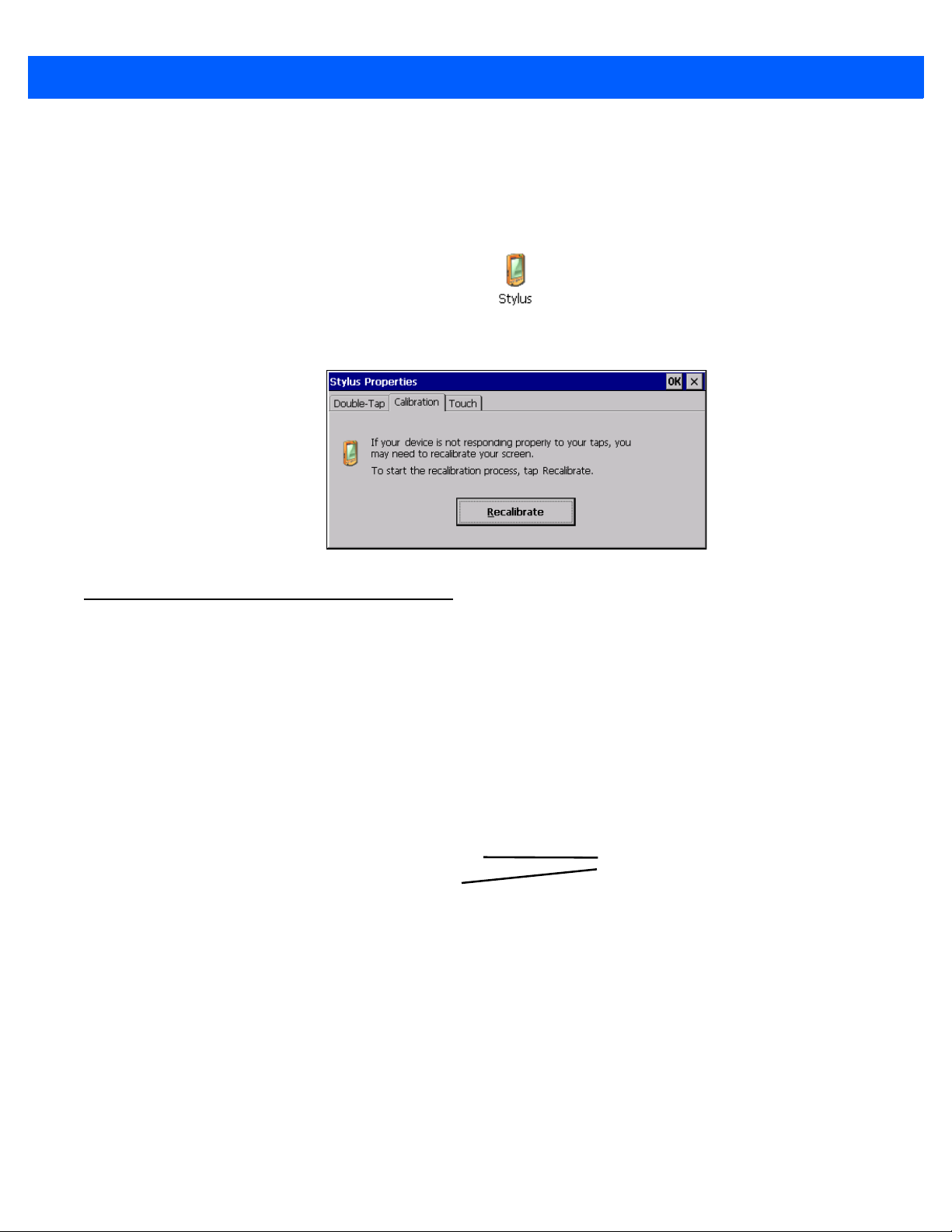
Calibrating the Touchscreen
If you find that the stylus pointer is not accurate when you tap on an item on the VH10 screen, use the Stylus
Properties dialog box in the Control Panel to recalibrate the screen.
• In the Control Panel, choose the Stylus icon to display the Stylus Properties window.
• Select the Calibration tab, and then choose the Recalibrate button.
• Follow the directions on the calibration screen to calibrate the screen.
Indicators
The VH10 uses LEDs (Light Emitting Diodes), onscreen messages, and audio tones as indicators.
LEDs
The VH10 is equipped with two coloured LEDs. This section outlines the conditions these LEDs indicate.
Figure 2-2
Power Status LED
The Power LED indicates system notifications and operating system status. It is also available for user-loaded
custom Windows Embedded CE applications.
LED Status Indicators

2 - 6 VH10 Vehicle-Mount Computer User Guide
Operating LED Behaviour Function
OFF The unit has no power (e.g. external power not
available, central power switch turned off). In this
state, pressing the [ENTER] key on the
keyboard will not wake up the unit.
Solid Amber with Slow Flashing Green The unit is ON, but operating from UPS battery.
Solid Green The unit is ON, operating from external power.
Solid Amber with Slow “Blipping” Green
(A 5 second period with 2% duty cycle:
green is on for 0.1 sec, off for 4.9 sec)
The unit is in Suspend, operating from UPS battery,
and cannot be turned on until external power is
present.
Warning LED
The red Warning LED indicates a fault situation, as shown here:
Operating LED Behaviour Function
OFF
Solid Red
Blinking Red Any other battery/charging fault, e.g. communication
No battery/charger faults.
Battery temperature is out of range for charging.
fault, charge timeout, defective battery pack.
Onscreen Indicators
The taskbar at the bottom of the screen displays a variety of system status indicators, including the Input Panel
button if you have chosen to show that option in the Taskbar and Start Menu settings.
Figure 2-3
Taskbar
The taskbar changes dynamically, and only those icons that are applicable are displayed. For example, if a
radio is not installed in your VH10, the radio signal icon is not displayed in the taskbar.
®
Windows
If you are using the touchscreen, you can either tap the Windows icon at the bottom left of the screen, or press
the [BLUE] + [MENU] key combination to display the Start Menu, and then tap on the desired application.
Modifier Key Indicators
[SHIFT], [CTRL], [ALT], [BLUE], and {ORANGE] are modifier keys that have onscreen indicators to show when
a key is active or locked. If a modifier key is pressed once to activate it, the key is displayed in the taskbar, for
example, pressing the [BLUE] key once displays a solid blue box in the taskbar. If a modifier key is pressed
twice, it is ‘locked on’ and the onscreen indicator is displayed with its icon underlined, for example, pressing
Start Menu

Getting To Know Your VH10 2 - 7
Good No Radio
Reception
Weak
Reception Link
[BLUE] twice displays solid blue box with an underline in the taskbar. For detailed information on these keys
and all the keyboard functions, please refer to The Keyboard on page 2-1.
802.11 Radio Signal Quality
Increasing radio signal quality is represented by longer, filled bars within this icon.
Bluetooth Radio
This icon displayed in the taskbar represents the installed Bluetooth radio.
Input Panel
You can tap the Input Panel icon to activate the soft keyboard application.
Audio Indicators
The VH10 beeper emits a sound when a key is pressed, a keyboard character is rejected, scan input is
accepted or rejected, an operator’s entry does not match in a match field, etc. To adjust the volume, see
Volume Adjustments on page 3-66.
Scanners and Imagers
IMPORTANT It is critical that you review the “Laser Warnings” in the VH10 Vehicle-Mount Computer
Regulatory & Warranty Guide (PN 8000279) before using any of the scanners described
in this chapter.
The VH10 supports a wide range of scanner options to address a variety of user application requirements.
Decoded scanners must be configured by scanning special configuration barcodes. In these cases, the
scanner manufacturer provides programming manuals for configuration purposes. Refer to the following
sections for detailed information:
• Supported Types: Handheld scanners and imagers connected via USB, RS-232, or Bluetooth, see Exter-
nal Barcode Scanners on page A-3.
• Interface: FF UART RS-232 port or USB port, see Appendix B: Port Pinouts.
• Configuration: Scanners on page 3-48 and Manage Triggers on page 3-32.
• Scanning Techniques on page 2-7 below outlines the mechanics of a successful scan.
• Troubleshooting on page 2-8 below provides some helpful suggestions should the scan fail.
Scanning Techniques
• Hold the scanner at an angle. Do not hold it perpendicular to the barcode.
• Do not hold the scanner directly over the barcode. In this position, light can reflect back into the scanner’s
exit window and prevent a successful decode.
• Scan the entire barcode. If you are using a 1D or PDF laser scanner, make certain that the scan beam
crosses every bar and space on the barcode, including the margins on either end of the symbol.

2 - 8 VH10 Vehicle-Mount Computer User Guide
• If you are using a 2D imaging scanner, make certain the red, oval shaped framing mark is centered within
the barcode you want to scan.
• When using imaging scanners, do not move the scanner while decoding the barcode. Movement blurs
the image.
• Hold the scanner farther away for larger barcodes.
• Hold the scanner closer for barcodes with bars that are close together.
Scan LED Indicators
External scanners have integrated LED indicators that are not controlled by the VH10.
Troubleshooting
If the scanner is not working, investigate the following:
• Is the VH10 on?
• Check that the scanner settings are correctly configured (see Scanners on page 3-48).
• Check the barcode to make sure it is not damaged. Try scanning a different barcode to verify that the
problem is not with the barcode.
• Check that the barcode is within the proper range.
• Does the computer display the warning without scanning? This suggests a hardware problem in the VH10.
• Is the laser beam scanning across the barcode?
• Once the scan beam has stopped, check the scanner window for dirt or fogging.
Operating Two Dimensional (2D) Imagers
An imager scanner takes a snap shot of a single barcode or multiple barcodes (at one time). It can find a
barcode regardless of its orientation — that is, even a barcode printed at a 45 degree angle to the scanner will
be decoded successfully.
NOTE When scanning multiple barcodes, ensure that all of the desired barcodes are within the field of
view of the scanner. It is possible that even when all barcodes are within the field of view, not all of
them will be decoded. Only successfully decoded barcodes are passed to the application program. The application program then issues a warning, asking that you scan the missing barcodes.
When scanning a single barcode, ensure that only the desired barcode is within the field of view
of the scanner.
Because imager scanners generally have a shorter depth of field than laser scanners, some practise may be
required to find the optimal distance from the types of barcodes being scanned. Although the imager includes
illumination LEDs, ambient light will help the imager decode the barcodes, especially if the barcode is far from
the scanner.
 Loading...