

Page 1
Without power pre-regulator
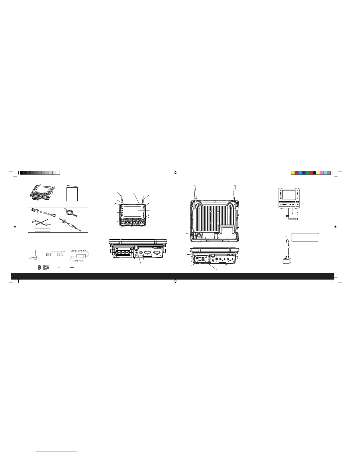
VEHICLE DC SUPPLY CONNECTIONS
OPTIONAL PARTS
Magmount and remote
external antenna
CONTENTS OF THE BOX
The VH10
This guide and any additional
documentation (dependent on order)
OVER
>
FRONT
Extension wire
Extension power cable
Cable kit CA1220 includes an extension power cable with additional
lines to connect to the Ignition Switch.
Cable kit CA1210 includes an extension power cable without lines for
the Ignition Switch.
Diode/choke assembly
Fuse assembly
DO NOT USE
Mounting hardware is packed separately, according to your order.
Adaptor cable with lines for
ignition switch
AC power adaptor
VH10 FEATURES
Display
SYM key
ENTER/Power key
UART RS-232 ports
BOTTOM
Power LED
Warning LED
Power button
Type B Micro-USB port (inside dome
plate - for service personnel only)
Function keys
Macro keys
Blue Modifier key
Antenna
(optional)
Orange Modifier key
Antenna
(optional)
Cable bay cover
Power cable
Audio jack
USB host port
DB9 screen blanking cable
Lines to ignition switch
(optional)
VH10 power cable
Vehicle DC power source
(12VDC to 48VDC nominal)
Positive
Negative
connection
connection
Extension power
cable
Extension wire
Fuse
DB9 cable
Lines to screen-blanking
sensor (optional)
Caution: Do not use the
diode/choke assembly in the
Extension Power Cable kit
Beeper
BACK
Vent
Ground lug
Powered USB host port
Unused ports should be covered with dust caps.
Strain
relief
brackets
Cable bay cover removed
Function keys and
Macro keys
PORTS
8000282.indd 1 10/14/2014 6:26:22 PM
Page 2
Sept 3, 2014
PN 8000282-001.A
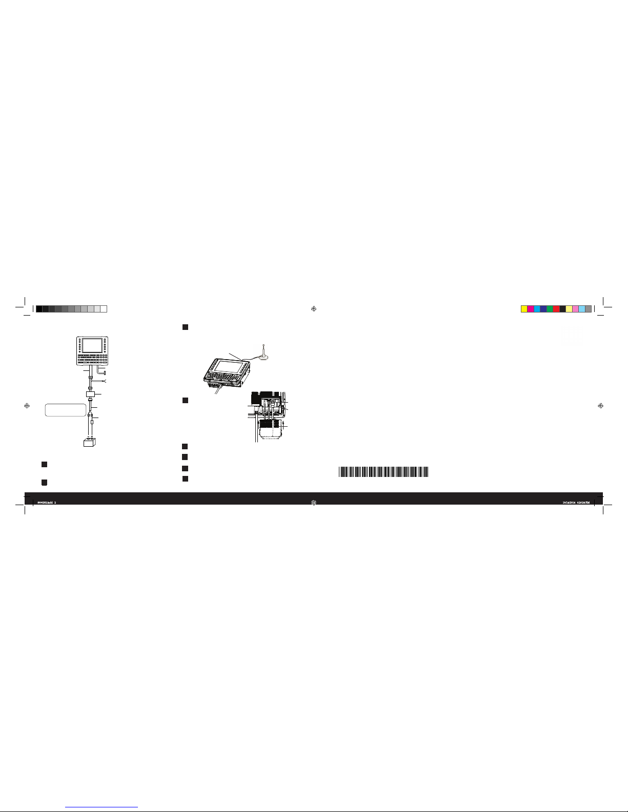
GETTING STARTED
1
2
3
5
Attach the mount to the VH10 and to the vehicle. Refer to the
mounting instructions in the VH10 Vehicle-Mount Computer User
Manual, PN 8000275.
Position the VH10 in the vehicle.
Narrowband radio: Attach the antenna, following the
instructions on the package.
Wi-Fi radio: Connect the external magmount antenna,
if needed.
6
7
8
4
Antenna connector
Mount the antenna
so that it is vertical
Connect peripherals to the
VH10, placing their cables
into the strain relief brackets
inside the cable bay. Then
replace the cover.
Connect the VH10 to the vehicle DC supply.
To power the unit on or off, press the Power button located at
the top of the unit.
Calibrate the touchscreen, if necessary.
Configure the radio, software, and peripherals. Refer to the VH10
Vehicle-Mount Computer User Manual, PN 8000275.
8 0 0 0 2 8 2 - 0 0 1
Vehicle DC power source
(48VDC to 72VDC nominal)
Power pre-regulator
Extension power cable
Extension wire
(without ignition switch)
Positive
Negative
connection
connection
Fuse
VH10 power cable
DB9 cable
Lines to screen-blanking
sensor (optional)
Lines to ignition switch (optional)
Caution: Do not use the
diode/choke assembly in the
Extension Power Cable kit
(Model PS1370)
With power pre-regulator
VEHICLE DC SUPPLY CONNECTIONS
Strain
relief
brackets
Bottom of VH10 with cable bay
cover removed.
Cable bay
Cable bay
cover
Symbol reserves the right to make changes to any product to improve reliability, function, or design.
Symbol does not assume any product liability arising out of, or in connection with, the application or use
of any product, circuit, or application described herein.
No license is granted, either expressly or by implication, estoppel, or otherwise under any patent right
or patent, covering or relating to any combination, system, apparatus, machine, material, method, or
process in which Symbol products might be used. An implied license exists only for equipment, circuit,
and subsystems contained in Symbol Products.
Symbol Technologies, Inc.
Holtsville, NY 11742, U.S.A.
All trademarks are the property of their respective owners.
© Copyright 2014. All rights reserved.
VH10 VEHICLE-MOUNT COMPUTER
Quick Start Guide
8000282.indd 2 10/14/2014 6:26:24 PM
8516N
 Loading...