


VC8300
8" Vehicle-Mounted Computer
User Guide
for Android™ 10
MN-003872-02EN Rev. A

ZEBRA and the stylized Zebra head are trademarks of Zebra Technologies Corporation, registered in many
jurisdictions worldwide. Google, Android, Google Play and other marks are trademarks of Google LLC; All
other trademarks are the property of their respective owners. ©2021 Zebra Technologies Corporation and/or
its affiliates. All rights reserved.
COPYRIGHTS & TRADEMARKS: For complete copyright and trademark information, go to
zebra.com/copyright
.
WARRANTY: For complete warranty information, go to zebra.com/warranty
END USER LICENSE AGREEMENT: For complete EULA information, go to zebra.com/eula
Terms of Use
• Proprietary Statement
This manual contains proprietary information of Zebra Technologies Corporation and its subsidiaries
(“Zebra Technologies”). It is intended solely for the information and use of parties operating and maintaining
the equipment described herein. Such proprietary information may not be used, reproduced, or disclosed to
any other parties for any other purpose without the express, written permission of Zebra Technologies.
• Product Improvements
Continuous improvement of products is a policy of Zebra Technologies. All specifications and designs are
subject to change without notice.
• Liability Disclaimer
Zebra Technologies takes steps to ensure that its published Engineering specifications and manuals are
correct; however, errors do occur. Zebra Technologies reserves the right to correct any such errors and
disclaims liability resulting therefrom.
• Limitation of Liability
In no event shall Zebra Technologies or anyone else involved in the creation, production, or delivery of the
accompanying product (including hardware and software) be liable for any damages whatsoever (including,
without limitation, consequential damages including loss of business profits, business interruption, or loss of
business information) arising out of the use of, the results of use of, or inability to use such product, even if
Zebra Technologies has been advised of the possibility of such damages. Some jurisdictions do not allow
the exclusion or limitation of incidental or consequential damages, so the above limitation or exclusion may
not apply to you.
.
.
Revision History
Changes to the original guide are listed below:
Change Date Description
-01 Rev A 9/2020 Initial release
-02 Rev A 10/2021 Updated GMS Restricted topic.
2

Table of Contents
About This Guide.............................................................................................................................. 11
Introduction .................................................................................................................... 11
Configurations................................................................................................................ 11
Software Versions.......................................................................................................... 11
Chapter Descriptions...................................................................................................... 12
Notational Conventions.................................................................................................. 12
Related Documents and Software ................................................................................. 13
Service Information ........................................................................................................ 13
Getting Started.................................................................................................................................. 14
Introduction .................................................................................................................... 14
Unpacking ...................................................................................................................... 14
Removing the Protective Film from the Display...................................................... 14
Safety............................................................................................................................. 14
Initial Operation Safety Considerations .................................................................. 15
Power Supply/Cable Safety.................................................................................... 15
External Devices Safety ......................................................................................... 15
Features......................................................................................................................... 16
Front Keys and LED Indicators ..................................................................................... 19
Front Keys .............................................................................................................. 19
LED Indicators ........................................................................................................ 19
Integrated Keyboard....................................................................................................... 20
Soft Input Panel.............................................................................................................. 22
Powering Up the Device................................................................................................. 22
Powering Down the Device............................................................................................ 22
Setting Up WLAN........................................................................................................... 22
Device Settings .............................................................................................................. 22
Heater Status ................................................................................................................. 22
3

Table of Contents
Installation......................................................................................................................................... 23
Introduction .................................................................................................................... 23
Overview ........................................................................................................................ 23
Mounting Instructions..................................................................................................... 23
Installing the Device....................................................................................................... 23
Electrical Installation............................................................................................... 23
Wiring Guidelines ............................................................................................. 24
Wiring Vehicle Power to the VC8300............................................................................. 25
External Antenna Installation.................................................................................. 26
Positioning the VC8300 in the Vehicle ................................................................... 26
Overview of the Assembly Steps............................................................................ 26
Cable Dust Cover ................................................................................................... 26
Strain Relief ............................................................................................................ 27
Installing the VC8300 on a Forklift.......................................................................... 27
Forklift Battery Replacement Conditions........................................................................ 28
Starting from Cold Soak................................................................................................. 28
Pre-Heat Mode ....................................................................................................... 29
Installing the Power Pre-Regulator ................................................................................ 29
Non-Vehicle Installations................................................................................................ 30
Screen Blanking Wiring.................................................................................................. 31
Connecting Switch for Screen Blanking ................................................................. 31
Using the Device............................................................................................................................... 33
Home Screen ................................................................................................................. 33
Setting Home Screen Rotation ............................................................................... 34
Status Bar............................................................................................................... 34
Notification Icons.............................................................................................. 35
Status Icons ..................................................................................................... 36
Managing Notifications ........................................................................................... 37
Opening the Quick Access Panel ........................................................................... 37
Quick Access Panel Icons................................................................................ 38
Editing Icons on the Quick Settings Bar ................................................................. 38
Battery Management...................................................................................................... 39
Monitoring Battery Usage ....................................................................................... 39
Low Battery Notification.......................................................................................... 39
Waking the Device ......................................................................................................... 39
USB Communication...................................................................................................... 40
Transferring Files.................................................................................................... 40
Transferring Photos ................................................................................................ 40
Disconnect from the Host Computer ...................................................................... 40
Transferring Files ........................................................................................................... 40
4

Table of Contents
Using a USB Drive.................................................................................................. 41
Disconnecting USB Drive ....................................................................................... 41
Applications ...................................................................................................................................... 42
Accessing Apps.............................................................................................................. 45
Switching Between Recent Apps............................................................................ 45
Battery Manager............................................................................................................. 45
Opening Battery Manager ...................................................................................... 45
Battery Manager Information Tab........................................................................... 45
DataWedge Demonstration............................................................................................ 47
Scanner Selection .................................................................................................. 48
Heater Control............................................................................................................... 49
Temperatures ......................................................................................................... 49
Serial Port Heater ................................................................................................... 49
USB Port Heater..................................................................................................... 49
Battery Heater ........................................................................................................ 49
Touch Panel Heater................................................................................................ 50
Keyboard Heater .................................................................................................... 50
PTT Express Voice Client .............................................................................................. 50
Speaker/Microphone Setup .................................................................................... 50
PTT Audible Indicators ........................................................................................... 50
PTT Notification Icons ............................................................................................ 51
Enabling PTT Communication................................................................................ 51
Selecting a Talk Group ........................................................................................... 52
PTT Communication............................................................................................... 52
Creating a Group Call ...................................................................................... 52
Responding with a Private Response .............................................................. 52
Disabling PTT Communication ............................................................................... 52
RxLogger....................................................................................................................... 53
RxLogger Configuration.......................................................................................... 53
Configuration File ................................................................................................... 53
Enabling Logging.................................................................................................... 53
Disabling Logging ................................................................................................... 53
Extracting Log Files ................................................................................................ 53
Backing Up ............................................................................................................. 53
RxLogger Utility ...................................................................................................... 54
Initiating the Main Chat Head........................................................................... 54
Removing the Main Chat Head ........................................................................ 54
Viewing Logs.................................................................................................... 54
Removing a Sub Chat Head Icon..................................................................... 54
Backing Up In Overlay View............................................................................. 54
VC Settings ................................................................................................................... 55
5

Table of Contents
Display.................................................................................................................... 55
Peripheral Power .................................................................................................... 55
Ignition Detection.................................................................................................... 55
WIFI Antenna Switching ......................................................................................... 55
Built-In Speaker ...................................................................................................... 55
Screen Blanking ..................................................................................................... 55
Velocity........................................................................................................................... 56
Data Capture ..................................................................................................................................... 57
Imaging ......................................................................................................................... 58
Operational Modes ................................................................................................. 58
Laser Scanning .............................................................................................................. 58
Scanning Considerations ............................................................................................... 58
Barcode Capture with RS6000 Bluetooth Ring Scanner................................................ 59
Barcode Capture with RS507/RS507x Hands-Free Imager........................................... 60
Bar Code Capture with RS5100..................................................................................... 61
Bar Code Capture with Zebra Scanner.......................................................................... 63
Connecting an RS-232 Scanner .................................................................................... 63
Connecting a USB Scanner ........................................................................................... 65
Connecting Using Simple Serial Interface........................................................ 65
Connecting Using HID Mode............................................................................ 66
Pairing the Ring Scanner ............................................................................................... 66
Pairing Using Simple Serial Interface ..................................................................... 66
Pairing Using Human Interface Device................................................................... 67
Pairing a DS3678 Scanner............................................................................................. 68
Pairing Using Simple Serial Interface ..................................................................... 68
Pairing a DS3678 Scanner Using Human Interface Device ................................... 69
DataWedge .................................................................................................................... 69
Enabling DataWedge.............................................................................................. 69
Disabling DataWedge............................................................................................. 70
DataWedge .................................................................................................................... 70
Enabling DataWedge.............................................................................................. 70
Disabling DataWedge............................................................................................. 70
Supported Decoders............................................................................................... 70
Wireless............................................................................................................................................. 73
Wireless Local Area Networks ....................................................................................... 73
Connecting to a Wi-Fi Network............................................................................... 74
Removing a Wi-Fi Network..................................................................................... 74
WLAN Configuration ...................................................................................................... 74
6

Table of Contents
Configuring a Secure Wi-Fi Network ...................................................................... 74
Manually Adding a Wi-Fi Network .......................................................................... 75
Configuring for a Proxy Server ............................................................................... 76
Configuring the Device to Use a Static IP Address ................................................ 77
Wi-Fi Preferences................................................................................................... 77
Additional Wi-Fi Settings ........................................................................................ 78
Wi-Fi Direct............................................................................................................. 79
Zebra Mobility Extensions.............................................................................................. 79
Bluetooth........................................................................................................................ 79
Adaptive Frequency Hopping ................................................................................. 80
Security................................................................................................................... 80
Bluetooth Profiles ................................................................................................... 80
Bluetooth Power States .......................................................................................... 81
Bluetooth Radio Power........................................................................................... 82
Enabling Bluetooth ........................................................................................... 82
Disabling Bluetooth .......................................................................................... 82
Discovering Bluetooth Device(s) ............................................................................ 82
Changing the Bluetooth Name ............................................................................... 82
Connecting to a Bluetooth Device .......................................................................... 83
Selecting Profiles on the Bluetooth Device............................................................. 83
Unpairing a Bluetooth Device ................................................................................. 83
Cast................................................................................................................................ 83
Accessories and Mounting.............................................................................................................. 84
Introduction .................................................................................................................... 84
Accessories.................................................................................................................... 84
VC8300 Antenna Options .............................................................................................. 85
VC8300 Mounting Accessories...................................................................................... 87
MT43XX RAM Mount.............................................................................................. 88
Optional Mounts ..................................................................................................... 88
Plate Bases for MT35XX Mounts ..................................................................... 90
MT4200 Quick Release Mount ............................................................................... 92
Assembling MT4200 ........................................................................................ 92
Attaching MT4200 to VC8300 ................................................................................ 93
MT4210 Adapter Bracket........................................................................................ 94
Settings.............................................................................................................................................. 95
Accessing Settings......................................................................................................... 95
Display Settings ............................................................................................................. 95
Setting the Screen Brightness Manually................................................................. 95
Setting Night Light .................................................................................................. 95
7

Table of Contents
Setting Screen Rotation.......................................................................................... 96
Setting Screen Timeout .......................................................................................... 96
Lock Screen Display............................................................................................... 96
Setting Font Size .................................................................................................... 96
Touch Panel Mode ................................................................................................. 97
Setting the Date and Time ............................................................................................. 97
Keyboard Backlight ........................................................................................................ 98
General Sound Setting................................................................................................... 98
Sound Options........................................................................................................ 98
Remapping a Button ...................................................................................................... 99
Keyboards...................................................................................................................... 99
Keyboard Configuration.......................................................................................... 99
Enabling Keyboards ......................................................................................... 99
Switching Between Keyboards....................................................................... 100
Using the Android and Gboard Keyboards........................................................... 100
Edit Text ......................................................................................................... 100
Entering Numbers, Symbols, and Special Characters ................................... 100
Using the Enterprise Keyboard............................................................................. 100
Numeric Tab................................................................................................... 100
Alpha Tab....................................................................................................... 101
Additional Character Tab ............................................................................... 101
Scan Tab........................................................................................................ 101
Soft Input Panel............................................................................................................ 103
Language Usage.......................................................................................................... 104
Changing the Language Setting ........................................................................... 104
Adding Words to the Dictionary ............................................................................ 104
Notifications.................................................................................................................. 104
Setting App Notifications ...................................................................................... 104
Viewing Notification Settings for All Apps ...................................................... 105
Controlling Lock Screen Notifications ............................................................ 105
Blink Light....................................................................................................... 105
Application Deployment................................................................................................................. 106
Security ........................................................................................................................ 106
Secure Certificates....................................................................................................... 106
Installing a Secure Certificate ...................................................................................... 106
Configuring Credential Storage Settings .............................................................. 107
Development Tools ...................................................................................................... 107
Android Application Development ........................................................................ 107
Development Workstation .............................................................................. 107
Enabling Developer Options .......................................................................... 107
EMDK for Android................................................................................................. 108
8

Table of Contents
StageNow ............................................................................................................. 108
GMS Restricted............................................................................................................ 108
ADB USB Setup........................................................................................................... 108
Enabling USB Debugging..................................................................................... 108
Application Installation ................................................................................................. 109
Installing Applications Using a USB Drive ............................................................ 109
Installing Applications Using the USB Connection ............................................... 110
Installing Applications Using the Android Debug Bridge ...................................... 110
Uninstalling an Application ................................................................................... 112
Performing a System Update....................................................................................... 112
Downloading the System Update Package .......................................................... 112
Performing a System Update Using USB Drive ................................................... 112
Performing a System Update Using ADB............................................................. 113
Verifying System Update Installation.................................................................... 114
Enterprise Reset .......................................................................................................... 114
Performing an Enterprise Reset From Device Settings........................................ 114
Downloading the Enterprise Reset Package ........................................................ 114
Performing an Enterprise Reset Using ADB......................................................... 115
Performing a Factory Reset ......................................................................................... 116
Downloading the Factory Reset Package ............................................................ 116
Performing a Factory Reset Using ADB ............................................................... 117
Storage......................................................................................................................... 118
Random Access Memory ..................................................................................... 118
Viewing Memory............................................................................................. 118
Internal Storage .................................................................................................... 118
Viewing Internal Storage ................................................................................ 118
External Storage................................................................................................... 119
Viewing External Storage............................................................................... 119
Formatting a USB Drive as Portable Storage ................................................ 119
Enterprise Folder .................................................................................................. 119
Managing Apps ............................................................................................................ 119
App Details ........................................................................................................... 119
Managing Downloads................................................................................................... 120
Maintenance and Troubleshooting ............................................................................................... 121
Introduction .................................................................................................................. 121
Cleaning....................................................................................................................... 121
Housing Cleaning ................................................................................................. 121
Touchscreen Cleaning.......................................................................................... 121
Touchscreen ................................................................................................................ 121
Troubleshooting ........................................................................................................... 122
9

Table of Contents
Resetting the Device ............................................................................................ 122
Performing a Soft Reset................................................................................. 122
Performing a Hard Reset ............................................................................... 122
VC8300................................................................................................................. 123
Specifications ................................................................................................................................. 126
Drill Hole Dimensions................................................................................................... 126
Index ................................................................................................................................................ 127
10

About This Guide
Introduction
This guide provides instructions for setting up, operating, configuring, and maintaining the VC8300 8 inch
vehicle-mount computer.
NOTE: Screens and windows pictured in this guide are samples and can differ from actual screens.
WARNING: Before transporting, assembling, and starting the computer, please read this manual carefully
and follow all the safety guidelines and requirements.
Configurations
The VC8300 offers different configurations to suit various work requirements. Some of the configuration
options include:
• Qualcomm Snapdragon 660 octa-core 2.2 GHz
• 4 GB RAM/ 32 GB Flash
• Sunlight Readable Display
• Internal and External Antenna
• Freezer Condensing
• Android 10 Google ™ Mobile Services (GMS)
• Basic I/O.
NOTE: For detailed configuration and part number information, contact your Zebra representative.
Software Versions
To determine the current software versions:
1. Swipe down from the Status bar to open the Quick Settings bar.
2. Touch > System.
3. Touch About phone.
4. Scroll to view the following information:
• Model
11

• Android version
• Android security patch level
• Kernel version
• Build number.
To determine the device serial number, touch About phone> Status.
• Serial number
Chapter Descriptions
Topics covered in this guide are as follows:
• Getting Started provides information on safety guidelines and initial VC8300 setup.
About This Guide
• Installation
• Using the Device provides information for operating the VC8300.
• Applications provides information on using applications installed on the VC8300.
• Data Capture explains how to capture data using the optional scanners.
• Wireless provides information on the various wireless options.
• Accessories and Mounting describes the accessories and mounting options available for the VC8300.
• Settings provides the settings for configuring the VC8300.
• Application Deployment provides information for developing and managing applications.
• Maintenance and Troubleshooting includes instructions on cleaning the VC8300 and provides
troubleshooting solutions for potential problems during device operations.
• Specifications summarizes the device’s intended operating environment and technical specifications.
provides instructions on installing the VC8300.
Notational Conventions
The following conventions are used in this document:
• Bold text is used to highlight the following:
• Dialog box, window and screen names
• Drop-down list and list box names
• Check box and radio button names
• Icons on a screen
• Key names on a keypad
• Button names on a screen.
• Chapters and sections in this guide
• Bullets (•) indicate:
• Action items
• Lists of alternatives
• Lists of required steps that are not necessarily sequential.
• Sequential lists (e.g., those that describe step-by-step procedures) appear as numbered lists.
12

About This Guide
Related Documents and Software
The following document provides more information about the VC8300 vehicle-mount computer.
• VC8300-8 Quick Reference Guide, p/n MN-003394-xx - includes setup information and regulatory
information.
• U-Mount Bracket Installation Guide, p/n MN-002931-xx - includes the instructions to install the U-Mount
Bracket Kit (KT-U-MOUNT-VC80-R) and dimensions.
• Adapter Bracket Kit for VC50 U-Mount Installation Guide, p/n MN-002932-xx - provides instruction on
installing the Adapter Bracket Kit (MNT-VC80-ADPA1-1) to attach the VC8300 to the VC5090 U-Mount.
• Adapter Bracket Kit for Honeywell U-Mount Installation Guide, p/n MN-002934-xx - provides instruction
on installing the Adapter Bracket Kit (MNT-VC80-ADPB1-1) to attach the VC8300 to the Honeywell
U-Mount Bracket.
For the latest version of this guide and all guides, go to: zebra.com/support
Service Information
If you have a problem with your equipment, contact Zebra Customer Support for your region. Contact
information is available at: zebra.com/support
When contacting support, please have the following information available:
• Serial number of the unit
• Model number or product name
• Software type and version number.
Zebra responds to calls by email, telephone or fax within the time limits set forth in support agreements.
If your problem cannot be solved by Zebra Customer Support, you may need to return your equipment for
servicing and will be given specific directions. Zebra is not responsible for any damages incurred during
shipment if the approved shipping container is not used. Shipping the units improperly can possibly void
the warranty.
If you purchased your Zebra business product from a Zebra business partner, contact that business
partner for support.
.
.
13

Getting Started
Introduction
The VC8300 is a rugged, vehicle mounted computer running Android 10 operating systems. Wireless
communications are supported over a 802.11 WLAN network. The Bluetooth module supports Bluetooth
printers and scanners. The VC8300-8 contains an integrated keyboard in either QWERTY or AZERTY
alphanumeric keyboard layout. It features 54 keys, 12 direct function keys, and a power button.
The VC8300 is intended for use in commercial and industrial applications with a focus on real time wireless
data transactions with options suiting materials handling applications in warehouses, manufacturing
facilities, ports, yards, and freezers.
Unpacking
CAUTION: Before operating the unit for the first time, carefully read Safety on page 14.
NOTE: Configure the VC8300 before fastening it to machines or vehicles.
Carefully remove all protective material from the device and save the shipping container for later storage
and shipping.
Inspect the equipment for damage. If any equipment is missing or damaged, contact the Zebra Support
Center immediately. See Service Information on page 13 for contact information.
Removing the Protective Film from the Display
The front display of the VC8300 is protected during transport by a transparent film. This film should remain
on the front display during assembly to avoid damage to the front display surface. Only remove the film
once all of the assembly work has been completed.
Safety
In order to prevent injury and damage, observe the following safety guidelines prior to assembly and
commissioning. The VC8300 is a multifunction vehicle computer for stationary and mobile use in
commercial environments such as, warehouses, manufacturing, yard/ports, and freezers. Different or
extraordinary usage is not permitted. For resulting damage, the user/operator of the VC8300 is solely
responsible. This also applies to any changes that you make to the device. Compliance with the safety
guidelines is particularly important for the proper use of this device. The manufacturer assumes no liability
for any and all damages that can be attributed to non-compliance with these guidelines.
14

Getting Started
Initial Operation Safety Considerations
• Installation/Initial Operation - Perform VC8300 installation in accordance with Installation on page 23.
Specifically, pay special attention to the various electrical potentials of the vehicle. Some vehicles have
a chassis that is connected to one of the battery supply lines (DC+ or DC-), while most
electrically-driven forklift vehicles have floating chassis, connected to neither DC+ or DC-. See Wiring
Vehicle Power to the VC8300 on page 25 for required wiring of vehicle power and fusing for the
VC8300.
• Risk of injury during transit or installation - The unit can fall during transit or installation and cause
injury. Always ensure that there are two persons available when installing or removing the device.
• Ensure that no persons are injured in case the mounting bracket breaks - The VC8300 may not be
installed in such a way that persons can be injured during a breaking of the mounting bracket (e.g.
fatigue break). If the device is mounted in a place where people can be injured if the bracket breaks,
apply appropriate safety measures (e.g. install a security cable in addition to the device bracket).
Power Supply/Cable Safety
The main power cord shall comply with the national safety regulations of the country where the equipment
is to be used.
• Operation in an emergency - In case of an emergency (such as damage to the power cable or housing,
or ingress of liquid or other foreign bodies), disconnect the device immediately from the power supply.
Contact technical support staff at once.
• Protection of the power supplies - If, after replacement, the fuse fed by the internal power supply blows,
send the device for servicing immediately.
• Danger of electrocution when cleaning/servicing the device - In order to avoid electrocution, always
disconnect the VC8300 from the power supply before cleaning or servicing the device.
• Do not exceed maximum voltage when charging the vehicle battery - While charging the vehicle
battery, disconnect the VC8300 from the battery or ensure that the maximum allowed input voltage of
the VC8300 is not exceeded.
• Do not switch on devices with damaged cables or plugs - Do not use the VC8300 if a cable or plug is
damaged. Replace damage parts immediately.
• Do not connect or disconnect cables during storms - Cables must never be connected or disconnected
during an electrical storm.
External Devices Safety
The use of additional wiring and other peripheral devices, which are not recommended or sold by the
manufacturer, can result in fire, electrocution or personal injury.
• If a power supply is used, only use the power supply recommended by the manufacturer.
• Before connecting or disconnecting peripheral devices (exception: USB devices), disconnect the
VC8300 from the power supply to avoid serious damage to both the VC8300 and the connected
devices.
15
Features
Getting Started
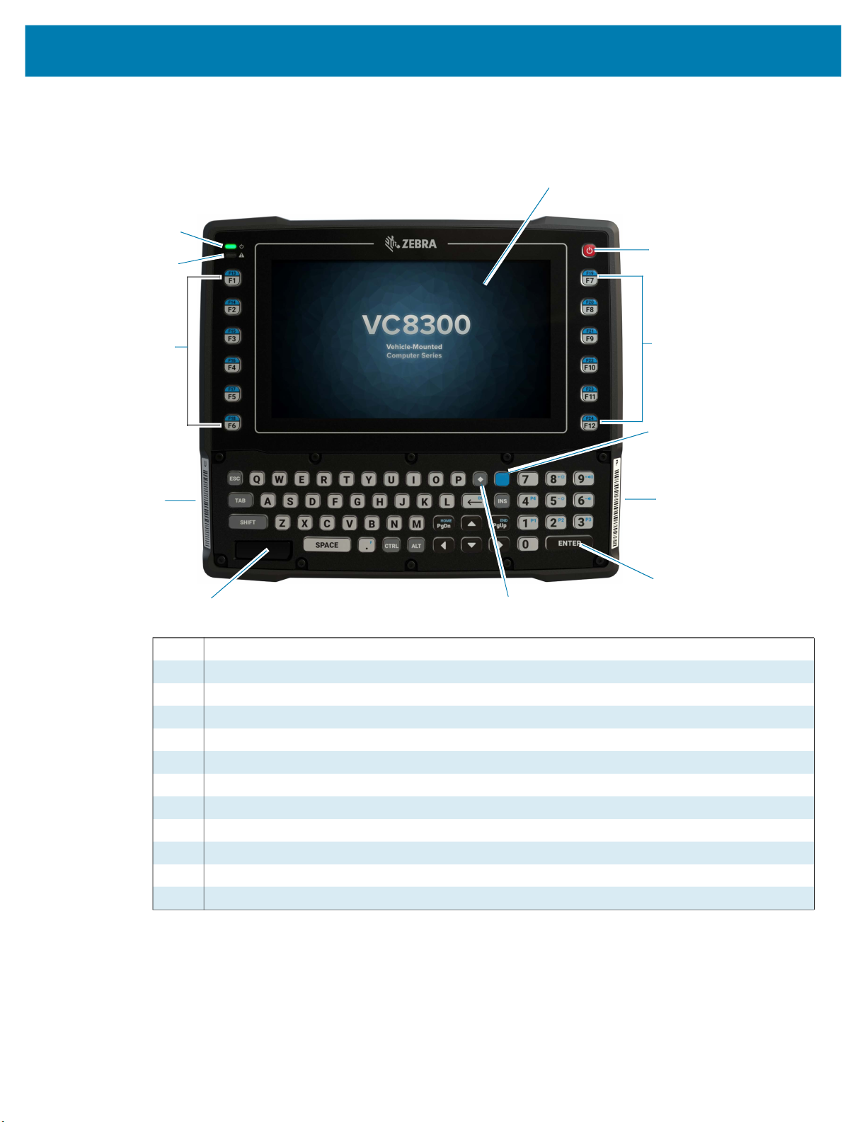
Figure 1 VC8300 8 inch Front View
1
12
2
11
10
9
8
1 Capacitive Touch Screen
2 Power Button
3 Programmable Keys
4 Blue Modifier Key
5 Pairing Bar Code
6 Enter Key
7 Diamond Key
8 Speaker
9 Unpairing Bar Code
10 Programmable Keys
11 Warning LED
12 Power LED
3
4
5
6
7
16

Figure 2 VC8300 8 inch Top View
802.11 a/b/g/n/ac Radio External Antenna Connectors
Getting Started
1
ANT 1 - Reverse Polarity SMA Jack (WLAN & BT) / External Main Antenna
ANT 2 - Reverse Polarity SMA Jack (WLAN) / External Aux Antenna
2
1 ANT 1
2 ANT 2
NOTE: Optional external Wi-Fi antennas are not shipped with the device and must be ordered as a
separate accessory. The device can be switched between internal and external antenna. For a complete
list of configurations see Table 12 on page 84.
Figure 3 VC8300 Back View with Dust Cover
1
5
4
1 UPS Battery
2 Dust Cover
3 Strain Relief (four)
4 Vent
5 RS-232 (two)
3
2
17

Getting Started
Figure 4 VC8300 Back View without Dust Cover
6
5
1 Standard USB
2 Powered USB
3 Speaker/Mic for M1000 only
4 Strain Relief
5 Power
6 Ground Lug
1
4
2
3
18

Front Keys and LED Indicators
The device has the following front bezel keys and LEDs:
Front Keys
Table 1 VC8300 8 inch Front Keys
Front Function
Power Powers the device on or off. Use to reset the device. See Resetting the Device
on page 122.
Diamond Key Opens the special character SIP.
Blue Modifier Key Modifies programmable macro keys allowing for an additional six programmable
keys. Press the Blue Modifier key twice to lock the key on and to unlock, press
the key once again.
Function Keys
Keyboard Use to enter text.
Bar Codes
Pairing Bar Code Pair peripheral Bluetooth scanners to the VC8300.
Unpairing Bar Code Un-pair peripheral Bluetooth scanners to the VC8300.
Speaker
Front Speaker Located on front bezel.
Function keys perform special, custom-defined functions within an application.
These keys are accessed by pressing one of the dedicated function keys on the
keyboard, or through the appropriate [Blue] key sequence.
Getting Started
LED Indicators
Table 2 LED Indicators
Indicator State Description
Power Off The device has no power and cannot be turned on.
Warning Off No battery or charger faults.
Amber The device has power and can be turned on.
Flashing Amber The unit is pre-heating.
Solid Green The unit is ON, operating from external power.
Slow Flashing Green The device is running with UPS/Internal Battery power, no
external power available.
Fast Flashing Green The device is in Sleep mode. Press Power button to wake the
device.
Solid Red Battery temperature is out of range for charging.
Blinking Red Any other battery/charging fault, e.g. communication fault,
charge timeout, or defective battery pack.
19

Integrated Keyboard
The device is available with an integrated keyboard in either QWERTY or AZERTY alphanumeric
keyboard layout. It features 54 keys, 12 direct function keys, and a power button.
Most of the keys on the keyboard operate much like a desktop computer. Where a key or key function is
not consistent with the keyboard, those differences are described in the following sections.
There are a number of modifier keys that provide access to additional keys and system functions.
See Keyboard Backlight on page 101 for information on adjusting the keyboard backlight.
Figure 5 Integrated Keyboard
Getting Started
20

Getting Started
Table 3 Key Descriptions
Key Function
Regular Keys
The Arrow Keys The arrow keys are located near the bottom of the keyboard, and are represented
on the keyboard as triangles pointing in different directions. The keys move the
cursor around the screen in the direction of the arrow: up, down, left, and right.
The left arrow key should not be confused with the backspace DEL key which is
depicted as a left arrow. The cursor is the flashing box or underline character that
indicates where the next character you type will appear.
The DEL Key The DEL key (represented on the keyboard as an arrow pointing left) is the
backspace key that moves the cursor one character to the left, erasing the
previous key stroke.
The [Blue] + DEL keys erase the character at the current cursor position.
The SHIFT Key
The CTRL and
ALT Keys
The TAB Key
The ESC Key
The SPACE Key
The INS Key
Function Keys
F1 - F12 Function keys perform special, custom-defined functions within an application.
The SHIFT key is used to display uppercase alpha characters. appears in the
status bar. Pressing the SHIFT key a second time locks the keys that all alpha
characters are uppercase. appears in the status bar. Press the SHIFT key
again to return to the default keypad functions.
The CTRL and ALT keys modify the function of the next key pressed and are
application dependent. or appears in the status bar. Pressing the CTRL or
ALT key a second time locks the keys. or appears in the status bar. Press
the key again to return to the default keypad functions.
Typically, the TAB key moves the cursor to the next field to the right or downward.
Generally, this key is used as a keyboard shortcut to close the current menu,
dialog box, or activity.
Pressing this key inserts a blank space between characters. In a dialog box,
pressing the SPACE key enables or disables a check box.
The INS key inserts a character at the cursor position.
These keys are accessed by pressing one of the dedicated function keys on the
keyboard, or through the appropriate [Blue] key sequence.
To access the blue function keys, first press the [Blue] key followed by the
appropriate function key.
Function keys can be used with the operating system or another application.
Programmable Keys
P1 - P5 The device keyboard is equipped with a series of programmable keys that can be
programmed to replace frequently used keystrokes, along with the function of
executable keys like the ENTER key, the [BACKSPACE] key, any function key,
arrow key, etc.
Special Keys
Diamond Key The Diamond key provides access to commonly used symbolic characters.
Pressing the key brings up the soft input panel (SIP) on-screen keyboard, with
symbols mapped to each key.
Blue Key The [Blue] key provides access to additional keys. These functions are color
coded in blue print on the key caps.
21

Soft Input Panel
The SIP provides additional commonly used symbolic characters that do not appear on the integrated
keyboard. Press the Diamond key to show the SIP. Press the Diamond key a second time to lock the SIP
in place. Press the Diamond key a third time to hide the SIP. Press and hold up arrow/down arrow key and
slide up and down to re-position the SIP on the screen.
Figure 6 Soft Input Panel
Powering Up the Device
Power up the device after connecting all of the devices.
Getting Started
To power up the device, connect to an appropriate power supply and press the Power button (see Figure 1
on page 16) or the ignition signal.
CAUTION: Make sure there is a suitable disconnecting device such as a power switch or circuit breaker in
the power supply circuit. See Installing the Device on page 23 for more information.
Powering Down the Device
Always shut down the device as follows:
1. Press the Power button until the menu appears on the screen.
2. Touch Power off.
Setting Up WLAN
To connect to a WLAN, see Wireless on page 73.
Device Settings
The user can configure the device setting:
• Date and Time settings. See Setting the Date and Time on page 40.
• Display settings, see Display Settings on page 38.
• Sound settings, see General Sound Setting on page 41.
Heater Status
The device offers a unique heater system that enables continuous operations in freezer environments. See
Heater Control on page 49 for information about the heater settings.
22

Installation
Introduction
This chapter provides instructions on installing the device.
Overview
The device can be installed in a variety of ways:
• Position the device horizontally on a desk or mounted on a vehicle console.
• Wall mount the device using the optional wall mount (see VC8300 Mounting Accessories on page 87).
• Overhead mount on a lift truck cage using mounting hardware.
Depending on the vibration resistance and pivoting demands, mounting brackets, clamp foots or RAM
mount elements can also be used to attach the device. Contact your Zebra sales office to find out more
about the range of available installation options.
WARNING: The unit could fall during transit or installation/mounting and cause injury. Always ensure that
there are two people available when installing or removing the device.
Mounting Instructions
Follow and retain the mounting instructions included with assembly kit when installing the device. See
Safety on page 14 for safety instructions.
Installing the Device
Electrical Installation
There are various electrical potentials when installing the unit on a vehicle such as a forklift.
23
Installation
WARNING: Most electrically driven forklift vehicles have floating chassis connected to neither DC+ or DC-.
However, electrical faults can cause the battery + or - to be connected to the chassis via low resistance
paths. All connected peripherals must be completely isolated.
The device accepts DC power sources with a minimum of 10 VDC nominal and 48 VDC nominal. A Power
Pre-regulator is required for voltages above 48 VDC nominal.
Applying a voltage above 48 VDC nominal without the pre-regulator or reversing polarity may result in
permanent damage to the device and voids the product warranty.
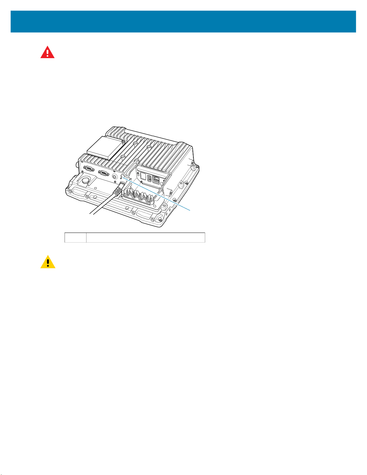
Figure 7 Ground Lug
1 Ground lug
CAUTION: Attach the device connecting cable as close to the battery as possible. Connecting the device
to large electrical loads, such as converters for the forklift motor may result in random restarts,
malfunctions and/or irreparable damage to the device.
To connect devices fed by other power sources to the device, such as printers, power up the peripheral
devices at the same time or after the device to avoid start-up problems, malfunctions or irreparable
damage to the device.
Wiring Guidelines
The metal chassis of the device is equipped with a ground lug (located on the underside adjacent to the
power cable) to provide additional ground to the vehicle. It is strongly recommended that a grounding strap
is used to connect the ground stud on the vehicle-mount to a solid, reliable contact point on the main
portion of the vehicle chassis. It must not be connected to battery negative or terminal block.
As with other vehicle cables, carefully consider the routing of the ground strap to ensure it does not pose a
hazard to the operator or the safe operation of the vehicle. If necessary, secure the ground strap with cable
ties or some other mechanical means to prevent loops or loose lengths of wire from catching on stationary
items when the vehicle is in motion.
1
Before installing the cables between the mount and other devices, consider the following:
• Ensure that drilling holes do not damage the vehicle or its wiring.
• Protect cable runs from pinching, overheating and physical damage.
• Use grommets to protect cables that pass through metal.
24

Installation
• Use plastic straps and tie-downs to secure cables and connectors in their desired location, away from
areas where they may get snagged or pulled.
• Keep cables away from heat sources, grease, battery acid and other potential hazards.
• Keep cables away from control pedals and other moving parts that may damage the cables or interfere
with the operation of the vehicle.
CAUTION: Make sure the cables run inside the roll cage of the vehicle.
If the device is installed in an environment where earth ground is present such as a vehicle with metal
wheels running on a metal track, or is powered by the AC/DC adapter in a permanent installation, the
ground lug must be connected to the ground structure.
Wiring Vehicle Power to the VC8300
WARNING: Applying voltage above the input voltage rating or reversing polarity may result in permanent
damage to the VC8300 and void the product warranty.
An extension power cable is used to wire the VC8300 to the truck battery (order cable separately, see
Accessories on page 84). Wire this cable to a filtered, fused (15A max) accessory supply on the vehicle.
Follow the installation instructions supplied with the extension cable.
Additional wiring (minimum 14 gauge), connectors or disconnects used should be rated for at least 300
VDC, 15A.
When connecting the extension power cable:
• If a power extension cable with ignition sense is used, ensure that the ignition sense wires (18AWG
wires in red and black leads) and the power wires (14AWG in red and black leads) are reliably secured
away from each other, or are separated with reliably secured certified insulation. Minimum 2.8 mm
distance, or 0.4 mm distance through insulation is required for the separation.
• The red lead of the 14AWG power cables attach to the vehicles battery positive terminal. The 14AWG
black lead connects to the vehicle’s battery negative terminal. This should be connected to a proper
terminal block and not to the vehicle body. An optional grounding strap wire (sourced separately) may
be connected to the ground lug of the VC8300 terminal connector bay and to the vehicle chassis.
• You may have the option to connect power before or after the key switch. Though the VC8300 is
equipped with a UPS, a proper shut down is recommended using the Power Off procedure. If it is wired
after the key switch, the operator must shut down the VC8300 using the Power Off procedure before
turning off the vehicle. If it is wired before the key switch, then to avoid excessive drain on the vehicle
battery, either the operator should shut it down when the vehicle is to be left off for an extended period,
or the ignition cable shut down wire should be connected and the VC8300 configured to shut down
automatically.
• An appropriate fuse type must be used with the power extension cable according to the installation
instructions. For main power cable, use 3AB, 15A, 250V, slow blow fuse. For ignition sense input, use
3AB, 0.3A, 250V, slow blow fuse.
NOTE: The VC8300 supports the ignition sense feature that detects when the ignition switch or key switch
is On or Off to allow automatic computer start up or shut down (with delay as needed).
When wiring the ignition sense wires (18AWG in red and black), the red 18AWG wire is connected to a
positive DC voltage source switched on by the ignition. The black 18AWG wire is connected to ground
reference of this switched ignition source.
25

External Antenna Installation
To install an external antenna:
1. Align the antenna connector with the connector on top of the VC8300.
2. Insert the antenna connector onto the VC8300 connector.
3. Tighten the antenna connector.
Installation
4. Swipe up from the bottom of the Home screen and touch VC Setting .
5. Touch Choose Antenna.
6. Touch External Antenna.
7. Touch Home.
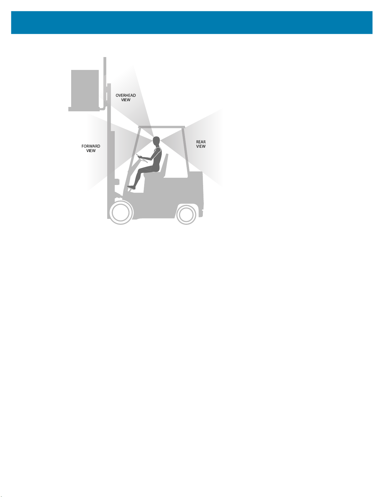
Positioning the VC8300 in the Vehicle
When positioning the VC8300 on the vehicle:
• The driver's field of view must be kept free.
• Plan for sufficient space if a keyboard and scanner are installed with the VC8300.
• No part of the VC8300 system may project beyond the vehicle.
Overview of the Assembly Steps
Before fastening the VC8300 to the vehicle:
• Configure shut down automation.
• Prepare the forklift such as ignition connection and correct voltage.
• It is recommended to fasten the bracket to the vehicle and then install the VC8300 to the bracket.
Cable Dust Cover
For the dust cover location, see VC8300 Back View with Dust Cover on page 17.
26

CAUTION: Turn on external peripheral devices with their own power supply at the same time or after the
VC8300. If this is not possible, ensure that the VC8300 is adequately protected from power leakage
caused by an external device.
Strain Relief
CAUTION: For safety reasons, install the supplied cable cover for the external ports prior to using the
VC8300.
After the VC8300 and bracket are fastened, prepare the strain relief as follows:
1. Install the cables loosely on the strain relief rail (see Figure 4 on page 18).
2. As far as possible, route cables leading to or away from the unit next to one another without crossing.
3. Fasten the cables into the strain relief rail precisely at the positions at which the cable openings in the
cable cover are located.
Installing the VC8300 on a Forklift
CAUTION: Tighten peripherals with thumbscrews by hand only. Do not use tools for tightening
thumbscrews.
Installation
NOTE: If installing peripherals, allow enough space when selecting a mounting location.
1. Attach the desired mount to the VC8300. See VC8300 Mounting Accessories on page 87 for detailed
mounting options and instructions.
2. Attach the mounted VC8300 to the vehicle and position in a location that does not obstruct the
operator’s view.
3. If using an external antenna, connect antenna in a vertical position to the VC8300.
4. Connect peripherals to the VC8300. Place the cables in the strain relief brackets inside the dust cover
and replace the dust cover (see Figure 3 on page 17).
5. Connect the VC8300 to the vehicle DC supply.
6. Press the Power button to turn the device
On or Off
(see
Figure 2 on page 17).
27
Installation
Figure 8 View Obstruction Considerations
Forklift Battery Replacement Conditions
The VC8300 maintains normal function of applications and connections during and after forklift battery
replacement.
Replace the forklift battery at any point during a shift and/or while the VC8300 is fully running.
The forklift battery may be replaced under following condition: VC8300 external temperature range: -30°C
to +50° C (-22°F to 122°F).
During forklift battery replacement (VC8300 is running on UPS battery), both Android and the VC8300 are
monitoring remaining UPS battery capacity. The default Low Battery notification threshold is set to 30%.
The Critical Battery threshold is set to 7%. If UPS battery is discharged below 7%, the VC8300
automatically shuts down.
Starting from Cold Soak
The VC8300 can to start up from a saturated cold soak at -30°C (or above) internal VC8300 temperature
when a valid external DC power source is present.
The VC8300 design minimizes wait time from -30°C cold soak to load the OS and have internal heaters to
assist system warm up.
From a -30°C cold soak condition, the VC8300 battery heater may be activated to warm the UPS battery to
an acceptable charging temperature if charging is needed. The conditions and time to heat the battery are
managed by the system. The OS load time and VC8300 ready for use time is independent of warming the
battery.
28

Installation
Pre-Heat Mode
When the device is powered down or suspended and the system temperature is below -25°C (-13°F), the
device enters pre-heat mode when the user presses the power key. This warms up critical internal
components with the heater elements prior to boot up.
When in Pre-heat mode the Power LED blinks amber.
The pre-heat mode lasts no longer than 15 minutes. The freezer configuration spends less time in Pre-heat
mode due to the additional Touch Panel heater.
The device remains powered down or suspended during Pre-heat mode. Once the system reaches the
adequate temperature, the device automatically boots up. The user is not required to press the power
button.
The device does not enter Pre-heat mode if it is outside the operating temperature range (-30°C to 50°C
(-22°F to 122°F)).
Installing the Power Pre-Regulator
IMPORTANT: The Zebra power extension cable positive lead is red and the negative lead is black.
It is recommended that all connections be secured with electrical tape or heat shrink to prevent
contaminants from degrading the connection.
To install the power pre-regulator:
1. Attach the pre-regulator cable male connector to the Zebra power extension cable which is installed on
the vehicle.
2. Connect the pre-regulator cable female connector either directly to the VC8300 power cable, or to the
power extension cable. See Figure 9.
29
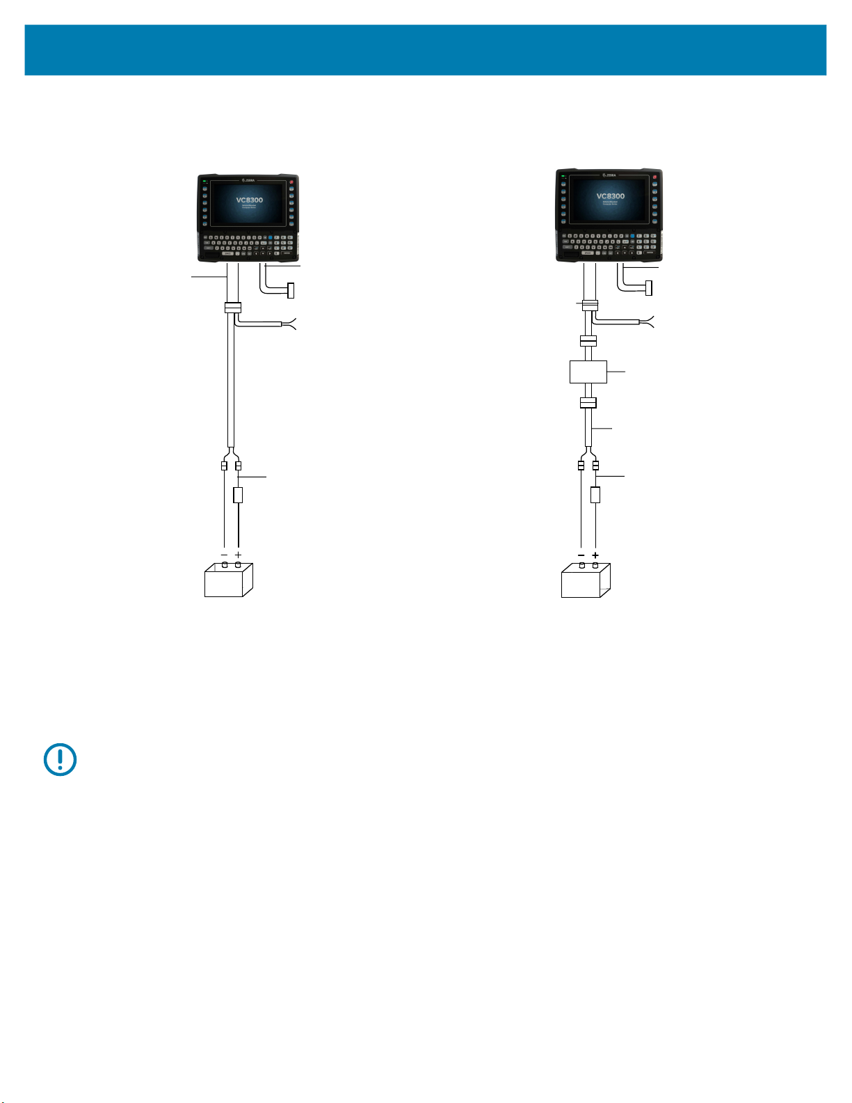
Figure 9 Connections To Vehicle DC Supply
M1M7M2M8M3M9M4
M10M5M11M6M12
Installation
Without Power Pre-regulator
For vehicles with DC power 48V or less
Power Cable
Power Extension
without Ignition Sense
(p/n CA1210)
Power Extension
with Ignition Sense
(p/n CA1220)
Negative
Connection
Fuse
Positive Connection
DB9 Cable
Lines to screen-blanking
sensor (optional)
Lines to ignition switch
(optional)
Extension Wire
With Power Pre-regulator
For vehicles with DC power greater than 48V
Power Cable
Power Extension for
Pre-Regulator with
Ignition Sense (p/n
CA1230)
Negative
Connection
Power Extension
without Ignition Sense
(p/n CA1210)
Fuse
Positive Connection
DB9 Cable
Lines to screen-blanking
sensor (optional)
Lines to ignition switch
(optional)
Power pre-regulator
Extension Wire
Vehicle DC Power Source
(12 VDC to 48 VDC nominal)
Non-Vehicle Installations
Using AC power, the VC8300 Vehicle-Mount Computer can be mounted at fixed locations adjacent to cross-dock
doors, manufacturing stations, or in offices.
Use the 100/240 VAC Power Supply (p/n PS1450) to power the computer from an AC source.
IMPORTANT: The AC/DC power supply is only intended for use at room temperature condition such as an office
environment.
Power On/Off with Ignition
The VC8300 is equipped with an ignition sense feature which shuts down the VC8300 when the vehicle ignition is
turned off and can power on the VC8300 when the ignition is switched on. To use this feature, a power extension
cable with ignition sense wires must be used and installed properly on the vehicle.
The cable in Figure 10 is the power extension cable (p/n CA1220) with two wires used to connect to vehicle ignition.
The red and black leads of the two 18AWG wires that connect to the key switch of the ignition and ground,
respectively. Once the wires are connected, the VC8300 may switch on or off depending on the state of the vehicle
ignition key. See VC Settings on page 56 to select power settings.
Vehicle DC Power Source
(12 VDC to 48 VDC nominal)
30
 Loading...