

VC80
M1M7M2M8M3M9M4
M10M5M11M6M12
MN002384A06
Vehicle-Mount Computer
User Guide


VC80
USER GUIDE
MN002384A06
Revision A
July 2018

ii VC80 User Guide
Revision History
Changes to the original guide are listed below:
Change Date Description
-01 Rev A 01/2016 Initial release.
-02 Rev A 12/2016 Add: WifiReconnectService; Kiosk application; Mounts Guides under Related
-03 Rev A 05/2017 Add VC80 Windows 10 configuration and software chapter.
-04 Rev A 04/2018 Update Table 5-1: Troubleshooting: updated cause "The optional external
-05 Rev A 06/2018 Corrected description for accessory power supply in Table 6-1 Accessories.
Documents; Properties under TekWedge.
speaker cable is connected without the speaker" to match VC80x guide.
Removed cause "Power is not enabled on the COM port" to match VC80x
guide.
Updated My-T-Soft section to clarify accessing Build-A-Board, added Build-ABoard screenshot.
-06 Rev. A 07/2018 Correct scancode.txt file location on page 7-2.

TABLE OF CONTENTS
Revision History................................................................................................................................. ii
About This Guide
Introduction....................................................................................................................................... ix
Configurations .......................................................................................................................................... x
VC80 Windows 7 Configurations ................................................................................................. x
Configurations for VC80 Windows 10.......................................................................................... x
Chapter Descriptions .............................................................................................................................. xi
Notational Conventions..................................................................................................................... xi
Related Documents and Software ..........................................................................................................xii
Service Information........................................................................................................................... xii
Chapter 1: Getting Started
Introduction .................................................................................................................................... 1-1
Unpacking ...................................................................................................................................... 1-1
Removing the Protective Film from the Display ....................................................................... 1-1
Safety ............................................................................................................................................. 1-2
Initial Operation Safety Considerations .................................................................................... 1-2
Power Supply/Cable Safety ..................................................................................................... 1-2
External Devices Safety ........................................................................................................... 1-2
VC80 Vehicle-Mount Computer Features ...................................................................................... 1-3
Front Keys and LED Indicators ...................................................................................................... 1-5
Front Keys ................................................................................................................................ 1-5
LED Indicators .......................................................................................................................... 1-6
Configuring GPS ............................................................................................................................ 1-6
Connecting External Devices ......................................................................................................... 1-7
Powering Up the VC80 .................................................................................................................. 1-7
Powering Down the VC80 .............................................................................................................. 1-7
Setting Up WLAN ........................................................................................................................... 1-8
Connecting WLAN on VC80 with Windows 7 ........................................................................... 1-8
Setting Up a New Connection or Network for VC80 with Win 7 ............................................... 1-9
Broadcom Help for Window 7 ................................................................................................ 1-10
Connecting WLAN on VC80 with Windows 10 ....................................................................... 1-11

iv VC80 User Guide
Setting Up a New Connection or Network for VC80 with Windows 10 .................................. 1-12
Broadcom Help for Window 10 .............................................................................................. 1-13
WiFiReconnectService ................................................................................................................. 1-14
Configuration .......................................................................................................................... 1-14
Event Viewer .......................................................................................................................... 1-15
Starting/Stopping Service ....................................................................................................... 1-15
Chapter 2: Installation
Introduction .................................................................................................................................... 2-1
Overview ........................................................................................................................................ 2-1
Mounting Instructions ..................................................................................................................... 2-1
Heater Status ................................................................................................................................. 2-1
Installing the VC80 ......................................................................................................................... 2-2
Electrical Installation ................................................................................................................ 2-2
Wiring Guidelines ............................................................................................................... 2-3
Wiring Vehicle Power to the VC80 ........................................................................................... 2-4
Positioning the VC80 in the Vehicle ......................................................................................... 2-5
Overview of the Assembly Steps ............................................................................................. 2-5
Cable Dust Cover ..................................................................................................................... 2-5
Strain Relief .............................................................................................................................. 2-5
Installing the VC80 on a Forklift ............................................................................................... 2-6
Forklift Battery Replacement Conditions ........................................................................................ 2-7
Starting from Cold Soak ................................................................................................................. 2-7
Installing the Power Pre-Regulator ................................................................................................ 2-8
Non-Vehicle Installations ............................................................................................................... 2-8
Power On/Off with Ignition ............................................................................................................. 2-9
Screen Blanking Wiring ................................................................................................................ 2-10
Connecting Switch for Screen Blanking ................................................................................. 2-10
Chapter 3: Software Windows 7
Introduction .................................................................................................................................... 3-1
Microsoft Windows Setup and Configuration ................................................................................. 3-1
Folder Structure ....................................................................................................................... 3-1
VC80 Windows 7 Software Components ....................................................................................... 3-2
VC80 Windows 7 Without Operating System ................................................................................ 3-2
Connecting VC80 Windows 7 to Terminal Emulation .................................................................... 3-3
TekTerm ................................................................................................................................... 3-3
VC80 Windows 7 Bar Code Scanners and Settings ...................................................................... 3-4
Serial Scanners for VC80 Windows 7 ...................................................................................... 3-4
USB Scanners for VC80 Windows 7 ........................................................................................ 3-6
Bluetooth Scanners for VC80 Windows 7 ................................................................................ 3-6
Pairing Bluetooth Scanners Using Bar Codes for VC80 Windows 7 .................................. 3-6
Settings for VC80 Windows 7 ........................................................................................................ 3-9
Quick Setup for VC80 Windows 7 .......................................................................................... 3-10
Touch Panel Calibration for VC80 Windows 7 ................................................................. 3-11
Manage VC Configuration for VC80 Windows 7 .............................................................. 3-16
Bezel Keyboard for VC80 Windows 7 .................................................................................... 3-17
Haptic Feedback for VC80 Windows 7 .................................................................................. 3-18

Table of Contents v
Heater Status for VC80 Windows 7 ....................................................................................... 3-19
Power for VC80 Windows 7 ................................................................................................... 3-20
Push To Talk for VC80 Windows 7 ........................................................................................ 3-21
Screen Blanking for VC80 Windows 7 ................................................................................... 3-22
System Info for VC80 Windows 7 .......................................................................................... 3-23
TekWedge for VC80 Windows 7 ............................................................................................ 3-24
UPS Battery Status for VC80 Windows 7 .............................................................................. 3-27
Data Logging for VC80 Windows 7 ........................................................................................ 3-28
My-T-Soft ..................................................................................................................................... 3-29
Windows Management Instrumentation ....................................................................................... 3-31
GPS ............................................................................................................................................. 3-31
Satellite Level ......................................................................................................................... 3-32
Location Coordinates ............................................................................................................. 3-32
U-Center Software ................................................................................................................. 3-32
Kiosk ............................................................................................................................................ 3-33
Configuration and Activation of Kiosk Mode .......................................................................... 3-33
Shell Settings ................................................................................................................... 3-33
Security ............................................................................................................................ 3-34
Lockdown ......................................................................................................................... 3-34
Monitor Utility ................................................................................................................... 3-34
Additional Software .......................................................................................................... 3-35
Completing Setup ............................................................................................................. 3-35
Exiting Kiosk Mode ........................................................................................................... 3-35
Launching Applications without UAC Prompt ................................................................... 3-36
Chapter 4: Software Windows 10
Introduction .................................................................................................................................... 4-1
Microsoft Windows Setup and Configuration ................................................................................. 4-1
Folder Structure ....................................................................................................................... 4-1
VC80 Widows 10 Software Components ....................................................................................... 4-2
VC80 Windows 10 Without Operating System .............................................................................. 4-2
Connecting VC80 Windows 10 to Terminal Emulation .................................................................. 4-3
TekTerm ................................................................................................................................... 4-3
VC80 Windows 10 Bar Code Scanners and Settings .................................................................... 4-4
Serial Scanners for VC80 Windows 10 .................................................................................... 4-4
USB Scanners for VC80 Windows 10 ...................................................................................... 4-6
Bluetooth Scanners for VC80 Windows 10 .............................................................................. 4-6
Pairing Bluetooth Scanners Using Bar Codes for VC80 Windows 10 ................................ 4-6
Settings for VC80 Windows 10 ...................................................................................................... 4-9
Quick Setup for VC80 Windows 10 ........................................................................................ 4-10
Touch Panel Calibration for VC80 Windows 10 ............................................................... 4-11
Manage VC Configuration for VC80 Windows 10 ............................................................ 4-16
Accelerometer for VC80 Windows 10 .................................................................................... 4-17
Bezel Keyboard for VC80 Windows 10 .................................................................................. 4-18
Haptic Feedback for VC80 Windows 10 ................................................................................ 4-19
Heater Status for VC80 Windows 10 ..................................................................................... 4-20
Power for VC80 Windows 10 ................................................................................................ 4-21
Push To Talk for VC80 Windows 10 ...................................................................................... 4-22
Screen Blanking for VC80 Windows 10 ................................................................................. 4-23

vi VC80 User Guide
System Info for VC80 Windows 10 ........................................................................................ 4-24
TekWedge for VC80 Windows 10 .......................................................................................... 4-25
UPS Battery Status for VC80 Windows 10 ............................................................................ 4-28
Data Logging for VC80 Windows 10 ...................................................................................... 4-29
My-T-Soft ..................................................................................................................................... 4-30
Windows Management Instrumentation ....................................................................................... 4-32
GPS ............................................................................................................................................. 4-32
Satellite Level ......................................................................................................................... 4-33
Location Coordinates ............................................................................................................. 4-33
U-Center Software ................................................................................................................. 4-33
Kiosk ............................................................................................................................................ 4-34
Configuration and Activation of Kiosk Mode .......................................................................... 4-34
Shell Settings ................................................................................................................... 4-34
Security ............................................................................................................................ 4-35
Lockdown ......................................................................................................................... 4-35
Monitor Utility ................................................................................................................... 4-35
Additional Software .......................................................................................................... 4-36
Completing Setup ............................................................................................................. 4-36
Exiting Kiosk Mode ........................................................................................................... 4-36
Launching Applications without UAC Prompt ................................................................... 4-37
Chapter 5: Maintenance and Troubleshooting
Introduction .................................................................................................................................... 5-1
Cleaning ........................................................................................................................................ 5-1
Housing Cleaning ..................................................................................................................... 5-1
Touchscreen Cleaning ............................................................................................................. 5-1
Touchscreen .................................................................................................................................. 5-2
Troubleshooting ............................................................................................................................. 5-3
Chapter 6: Accessories and Mounting
Introduction .................................................................................................................................... 6-1
Accessories .................................................................................................................................... 6-1
External Bar Code Scanners ......................................................................................................... 6-5
VC80 Antenna Options .................................................................................................................. 6-6
VC80 Mounting Accessories .......................................................................................................... 6-7
MT43XX RAM Mount ............................................................................................................... 6-8
Optional Mounts ....................................................................................................................... 6-9
Plate Bases for MT35XX Mounts ....................................................................................... 6-9
MT4200 Quick Release Mount ............................................................................................... 6-10
Assembling MT4200 ........................................................................................................ 6-10
Attaching MT4200 to VC80 .............................................................................................. 6-11
MT4210 Adaptor Bracket ....................................................................................................... 6-12
Chapter 7: Scancode Map
Introduction .................................................................................................................................... 7-1
Integrated Keypad .......................................................................................................................... 7-2

Table of Contents vii
Appendix A: Specifications
Introduction ................................................................................................................................... A-1
Technical Specifications ............................................................................................................... A-2
VC80 Drill Hole Dimensions .......................................................................................................... A-5

viii VC80 User Guide

ABOUT THIS GUIDE
Introduction
This guide provides instructions for setting up, op e rating, configuring, and maintaining the VC80 vehicle-mount
computer.
NOTE Screens and windows pictured in this guide are samples and can differ from actual screens.
WARNING! Before transporting, assembling, and start ing the computer , please read t his manual
carefully and follow all the safety guidelines and requirements.

x VC80 User Guide
Configurations
VC80 Windows 7 Configurations
The VC80 offers different configurations to suit various work requirements. Some of the configuration options
include:
•
Intel E3825 Dual Core, 1.33 GHz, 1 MB Cache, 2 GB RAM
•
Intel E3845 Quad Core, 1.91 GHz, 2 MB Cache, 4 GB RAM
•
SSD (32 GB or 64 GB)
•
Sunlight Readable Display
•
Internal Antenna
•
External Antenna
•
Freezer Condensing
•
Windows Embedded Standard 7
•
Windows 7 Professional for Embedded Systems
•
Basic I/O
•
CanBus
•
Ethernet
Configurations for VC80 Windows 10
The VC80 offers different configurations to suit various work requirements. Some of the configuration options
include:
•
Intel E3845 Quad Core, 1.91 GHz, 2 MB Cache, 4 GB RAM
•
SSD (64 GB)
•
Sunlight Readable Display
•
Internal Antenna
•
External Antenna
•
Freezer Condensing
•
Windows Embedded Standard 7
•
Windows 10 IoT Enterprise 2016 LTSB Entry
•
Basic I/O
•
CanBus
•
Ethernet
NOTE For detailed configuration and part number information, contact your Zebra representative.

About This Guide xi
Chapter Descriptions
Topics covered in this guide are as follows:
•
Chapter 1, Getting Started, provides information on safety guidelines and initial VC80 setup.
•
Chapter 2, Installation, provides instructions on installing the VC80.
•
Chapter 3, Software Windows 7, explains how to configure the VC80 with Windows 7.
•
Chapter 4, Software Windows 10, explains how to configure the VC80 with Windows 10.
•
Chapter 5, Maintenance and Troubleshooting, includes instructions on cleaning the VC80 and provides
troubleshooting solutions for potential problems during device operations.
•
Chapter 6, Accessories and Mounting, describes the accessories and mounting options available for the
VC80.
•
Chapter 7, Scancode Map, provides information on the integrated scancode maps for the VC80.
•
Appendix A, Specifications, summarizes the device’s intended operating environment and technical
specifications.
Notational Conventions
The following conventions are used in this document:
•
Italics are used to highlight the following:
• Chapters and sections in this guide
• Related documents.
•
Bold text is used to highlight the following:
• Dialog box, window and screen names
• Drop-down list and list bo x name s
• Check box and radio button names
• Icons on a screen
• Key names on a keypad
• Button names on a screen.
•
Bullets (•) indicate:
• Action items
• Lists of alternatives
• Lists of required step s th at ar e not ne ce ssa r ily seq ue nt ial.
•
Sequential lists (e.g., those that describe step-by-step procedures) appear as numbered lists.

xii VC80 User Guide
Related Documents and Software
The following document provides more information about the VC80 vehicle-mount computer.
•
VC80 Quick Reference Guide, p/n MN002383Axx - includes VC80 setup information and regulatory
information.
•
U-Mount Bracket Installation Guide, p/n MN-002931-xx - includes the instructions to install the U-Mount
Bracket Kit (KT-U-MOUNT-VC80-R) and dimensions.
•
Adapter Bracket Kit for VC50 U-Mount Installation Guide, p/n MN-002932-xx - provides instruction on
installing the Adapter Bracket Kit (MNT-VC80-ADPA1-1) to attach the VC80 to the VC5090 U-Mount.
•
Adapter Bracket Kit for Honeywell U-Mount Installation Guide, p/n MN-002934-xx - provides instruction on
installing the Adapter Bracket Kit (MNT-VC80-ADPB1-1) to attach the VC80 to the Honeywell U-Mount
Bracket.
For the latest version of this guide and all guides, go to: http://www.zebra.com/support
Service Information
If you have a problem with your equipment, contact Zebra Customer Support for your region . Contact information is
available at: http://www.zebra.com/support
When contacting support, please have the following information available:
•
Serial number of the unit
•
Model number or product name
•
Software type and version number.
Zebra responds to calls by email, telephone or fax within the time limits set forth in support agreements.
If your problem cannot be solved by Zebra Customer Support, you may need to return your equipment for servicing
and will be given specific directions. Zebra is not responsible for any damages incurred during shipment if the
approved shipping container is not used. Shipping the un its improperly can possibly void the warranty.
If you purchased your Zebra business product from a Zebra business partner, contact that business partner for
support.
.
.

CHAPTER 1 GETTING STARTED
Introduction
The VC80 is a rugged, vehicle mounted computer running Microso ft Windows Embedded Standard 7 and Windows
Professional for Embedded Systems operating systems. Wireless communications are supported over a 802.11
WLAN network. The Bluetooth module supports Bluetooth printers and scanners. The VC80 can be used with or
without an external keyboard. There are six programmable macro keys on the front bezel and when used with the
Blue modifier key, provides six additional programmable keys.
The VC80 is intended for use in commercial and industrial applications with a focus on real time wireless data
transactions with options suiting materials handling applications in warehouses, manufacturing facilities, ports,
yards, and freezers.
Unpacking
WARNING
NOTE
Carefully remove all protective material from the device and save the shipping container for later storage and
shipping.
Inspect the equipment for damage. If any equipment is missing or damaged, contact the Zebra Support Center
immediately. See Service Information on page xii for contact information.
!
Before operating the unit for the first time, carefully read Safety on page 1-2.
Configure the computer before fastening it to machines or vehicles.
Removing the Protective Film from the Display
The front display of the VC80 is protected during transport by a transparent film. This film should remain on the
front display during assembly to avoid damage to the front display surface. Only remove the film once all of the
assembly work has been completed.

1 - 2 VC80 User Guide
Safety
In order to prevent injury and damage, observe the following safety guidelines prior to assembly and
commissioning. The VC80 is a multifunction terminal for stationary and mobile use in commercial environments
such as, warehouses, manufacturing, yard/ports, and freezers. Different or extraordinary usage is not permitted.
For resulting damage, the user/operator of the VC80 is solely responsible. This also applies to any changes that
you make to the device. Compliance with the safety guidelines is particularly important for the proper use of this
device. The manufacturer assumes no liability for any and all damages that can be attributed to non-compliance
with these guidelines.
Initial Operation Safety Considerations
•
Installation/Initial Operation - Perform VC80 installation in accordance with Chapter 2, Installation.
Specifically, pay special attention to the various electrical potentials of the vehicle. Some vehicles have a
chassis that is connected to one of the battery supply lines (DC+ or DC-), while most electrically-driven forklift
vehicles have floating chassis, connected to neither DC+ or DC-. See Wiring Vehicle Power to the VC80 on
page 2-4 for required wiring of vehicle power and fusing for the VC80.
•
Risk of injury during transit or installation - The unit can fall during transit or installation and cause injury.
Always ensure that there are two persons available when installing or removing the device.
•
Ensure that no persons are injured in case the mounting bracket breaks - The VC80 may not be
installed in such a way that persons can be injured during a breaking of the mounting bracket (e.g. fatigue
break). If the device is mounted in a place where people can be injured if the bracket breaks, apply
appropriate safety measures (e.g. ins ta ll a secu rity cable in addition to the device bracket).
Power Supply/Cable Safety
The main power cord shall comply with the national safety regulations of the country where the equipment is to be
used.
•
Operation in an emergency - In case of an emergency (such as damage to the power cable or housing, or
ingress of liquid or other foreign bodies), disconnect the device immediately from the power supply. Contact
technical support staff at once.
•
Protection of the power supplies - If, after replacement, the fuse fed by the internal power supply blows,
send the device for servicing immediately.
•
Danger of electrocution when cleaning/servicing the device - In order to avoid electrocution, always
disconnect the VC80 from the power supply before cleaning or servicing the device.
•
Do not exceed maximum voltage when charging the vehicle battery - While charging the vehicle b attery,
disconnect the VC80 from the battery or ensure that the maximum allowed input voltage of the VC80 is not
exceeded.
•
Do not switch on devices with damaged cables or plugs - Do not use the VC80 if a cable or plug is
damaged. Replace damage parts immediately.
•
Do not connect or disconnect cables during storms - Cables must never be connected or disconnected
during an electrical storm.
External Devices Safety
The use of additional wiring and other peripheral devices, which are not recommended or sold by the manufacturer, can result in fire, electrocution or personal injury.
•
If a power supply is used, only use the power supply recommended by the manufacturer.
•
Before connecting or disconnecting peripheral devices (exception: USB devices), disconnect the VC80 from
the power supply to avoid serious damage to both the VC80 and the connected devices.

Getting Started 1 - 3
M1M7M2M8M3M9M4
M10M5M11M6M12
Speaker
On Screen
Keyboard
Speaker Volume/
Display Brightness
Power
Button
Pairing
Bar Code
Unpairing
Bar Code
Programmable
Macro Keys
(6 + 6)
Blue
Modifier
Key
LEDs
(three)
Resistive
Touch Screen
802.11 a/b/g/n/ac Radio External Antenna Connectors
ANT 1
ANT 2
ANT 3
ANT 1 - Reverse Polarity SMA Jack (WLAN) / External Main WiFi Antenna
ANT 2 - Reverse Polarity SMA Jack (WLAN + BT) / External WiFi Diversity or MIMO Antenna
ANT 3 - SMA Jack (GPS)
VC80 Vehicle-Mount Computer Features
Figure 1-1 VC80 Front View
Figure 1-2 VC80 Top View
NOTE
Antenna options are dependent on the VC80 configuration. Some configurations only have internal
antennas while other configurations have two or more external antenna connectors. WiFi antennas are
not shipped with the VC80 and must be ordered as a separate accessory.
1 - 4 VC80 User Guide
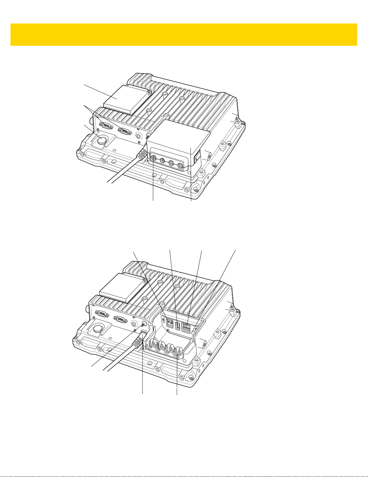
Dust
Cover
RS-232
(two)
UPS
Battery
Strain Relief
(four)
Vent
Ethernet or
CAN Bus
(optional)
Standard
USB
Powered
USB
Speaker/
Mic
Strain
Relief
Power
Ground
Lug
Figure 1-3 VC80 Back View with Dust Cover
Figure 1-4 VC80 Back View without Dust Cover

Getting Started 1 - 5
Front Keys and LED Indicators
The VC80 has the following front bezel keys and LEDs:
Front Keys
Table 1-1 VC80 Front Keys
Front Function
Power Keys
On/Off Button Powers the VC80 On or Off. To reset the device, press and ho ld the On/Off button for
at least seven seconds until the green LED changes to amber.
Speaker/Display Speaker volume and display brightness adjustment button. Use the (-) sign to
decrease volume/brightness and use the (+) to increase the volume/brightness.
Keyboard Display on screen keyboard.
Blue Modifier Key Modifies programmable macro keys allowing for an additional six programmab le keys.
Press the Blue Modifier key twice to lock the key on and to unlock, press the key once
again.
Macro Keys
Programmable
Bar Codes
Pairing Bar Code Pair peripheral Bluetooth scanners to the VC80.
Unpairing Bar Code Unpair peripheral Bluetooth scanners to the VC80.
Speaker
Front Speaker Located on front bezel.
Six programmable macro keys. When used with the Blue modifier key, six additional
programmable keys are provided. Keys may be mapped in the Control Panel by
assigning scancodes (see Chapter 7, Scancode Map) or macro mapping with
My-T-Soft.

1 - 6 VC80 User Guide
LED Indicators
Table 1-2 VC80 LED Indicators
Green/Amber
LED
Off Off Off No external power and the VC80 is not running on UPS.
Amber On Off Off External power is available but the VC80 is not turned On
Green On Off External power is available and the VC80 is turned ON.
Green Flashing
(50% Duty
Cycle On at
500ms Period)
Green Flashing
(25% Duty
Cycle On at
4000ms Period)
Green On Off Off Bezel keyboard keys: M1, M2, M3, M4, M5, M6
Green On Off On Bezel keyboard keys: M7, M8, M9, M10, M11, M12
Red LED Blue LED Description
(in shutdown or hibernate mode). The VC80 is ready to
be turned on and is currently charging the UPS battery.
The UPS battery is charging.
External power is removed. The VC80 is running on UPS
battery power.
Off Off The VC80 is in sleep mode.
Off On Off Warm up condition. The average of radio card and audio
NOTE
For fields in the above table without LED information, the LED can be On or Off dependent on user
actions and ambient temperature.
Configuring GPS
For VC80 configurations with GPS, see GPS on page 3-31 for information on setting up and configuring the GPS
with U-Center.
Flashing Red
(50% Duty
Cycle On at
500ms
Period)
Temperature related warning or error event in the
system. Average of radio card and audio codec temperature readings is either <-35° C or > +65° C. No action is
required if the OS is running. If the OS is in Sleep or
Hibernate state, then the EC should switch the VC80 Off.
codec temperature readings is between -35° C and 0° C.
The OS is not running. The Power Button is disabled.

Getting Started 1 - 7
Connecting External Devices
Disconnect the VC80 from the power supply before:
• Connecting or disconnecting external devices (e.g., scanner, keyboard).
• Connected to network.
CAUTION
Turn on external peripheral devices with power supplies at the same time or after turning on the VC80.
Ensure that the VC80 is adequately protected from power leakage caused by an external device.
Powering Up the VC80
Power up the VC80 after connecting all of the devices.
To power up the VC80, connect to an appr opriate power supply and press the Power button (see Figure 1-1) or the
ignition signal.
CAUTION
Make sure there is a suitable disconnecting device such as a power switch or circuit breaker in the
power supply circuit. See Installing the VC80 on page 2-2 for more information.
Powering Down the VC80
Always shut down the VC80 as follows:
1. Select Start.
2. Select Shut Down.
1 - 8 VC80 User Guide
Setting Up WLAN
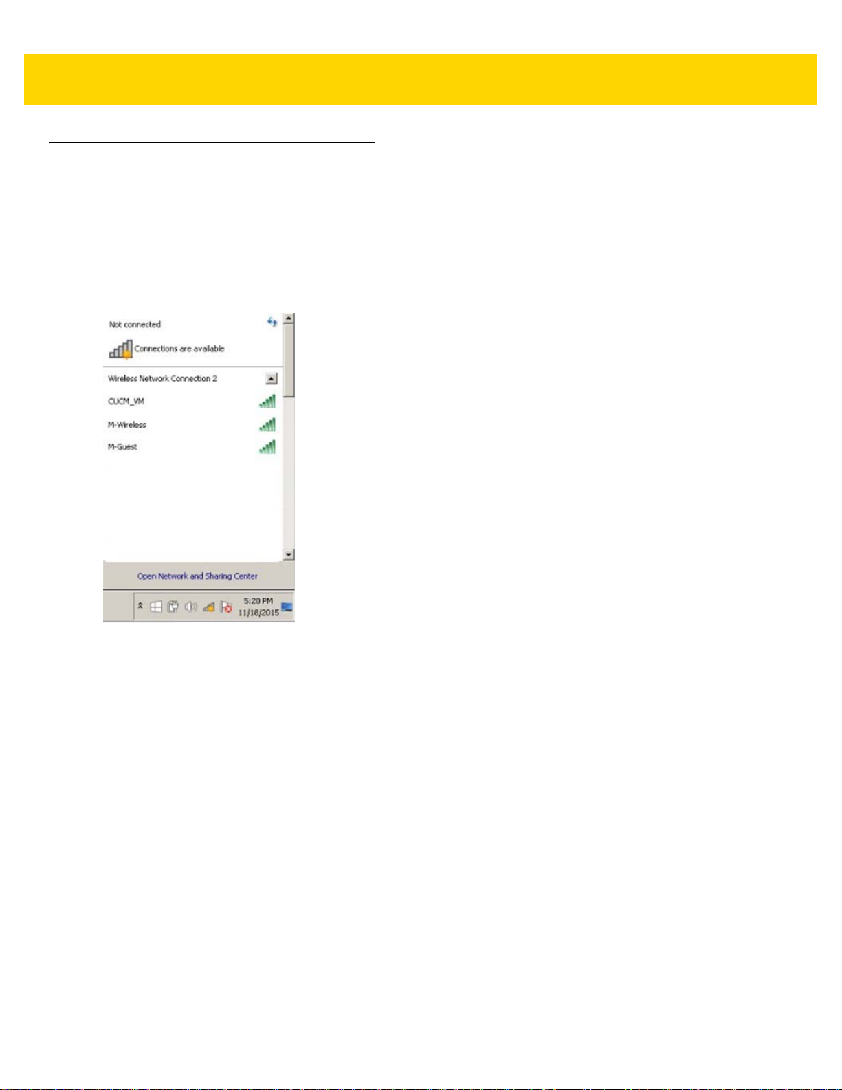
Connecting WLAN on VC80 with Windows 7
To connect to the WLAN:
1. Click on the WiFi icon in the system tray to display available WLAN networks.
2. Click on the desired network and select Connect.
Figure 1-5 WLAN Connection on VC80 with Win 7
Getting Started 1 - 9
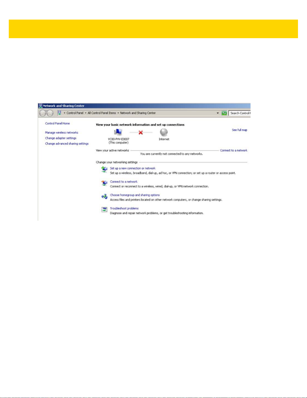
Setting Up a New Connection or Network for VC80 with Win 7
To set up a new connection or network:
1. Click on the WiFi icon in the system tray.
2. Select Open Network and Sharing Center (see Figure 1-5).
3. Select Set Up a New Connection or Network.
Figure 1-6 Setup New Connection or Network for VC80 with Windows 7
4. Choose a connection option.
5. Follow the prompts to complete setup.

1 - 10 VC80 User Guide
Broadcom Help for Window 7
The Broadcom Help utility assists with managing the WiFi connection or network.
To access Broadcom Help:
1. Go to Start > Control Panel > Broadcom Utility.
2. Select the Help tab on the top tool bar.
3. Select the desired topics for assistance.
Figure 1-7 Broadcom Help

Getting Started 1 - 11
Connecting WLAN on VC80 with Windows 10
To connect to the WLAN:
1. Left click on the WiFi icon in the system tray to display available WLAN networks.
2. Select the desired network and enter additional settings.
To manually connect to the WLAN:
1. Right click on the WiFi icon for networks that do not broadcast the SSID.
Figure 1-8 WLAN Connection on VC80 with Windows 10
1 - 12 VC80 User Guide
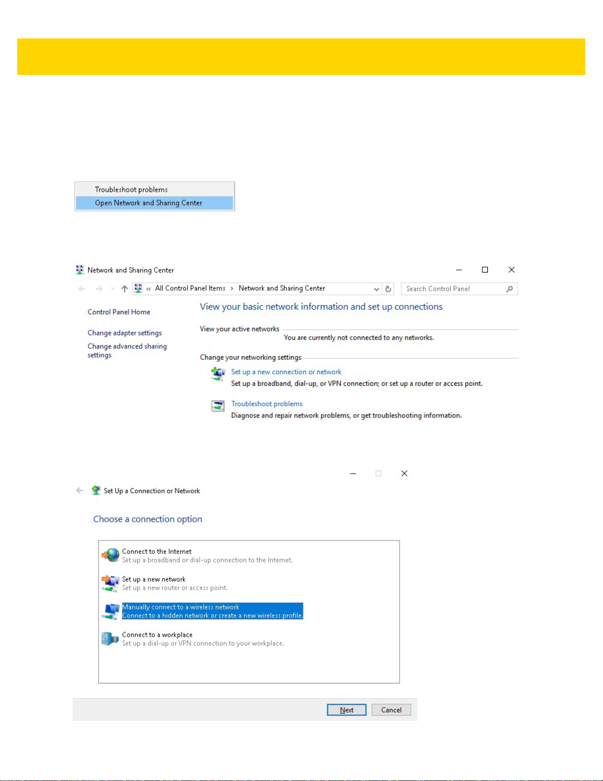
Setting Up a New Connection or Network for VC80 with Windows 10
To set up a new connection or network:
1. Right click on the WiFi icon in the system tray.
2. Select Open Network and Sharing Center (see Figure 1-9).
Figure 1-9 Open Network and Sharing Center for VC80 with Windows 10
3. Select Set Up a New Connection or Network.
Figure 1-10 Setup New Connection or Network for VC80 with Windows 10
4. Select Manually connect to a wireless network.
Figure 1-11 Manually Connect to a Wireless Network
Getting Started 1 - 13
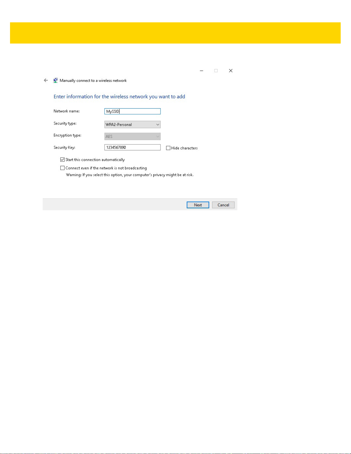
5. Enter wireless network information.
Figure 1-12 Enter Wireless Network Information
6. Select Next.
Broadcom Help for Window 10
The Broadcom Help utility is not available for Windows 10.

1 - 14 VC80 User Guide
WiFiReconnectService
The WifiReconnectService is a lightweight Windows Service that is designed to run in the background on any
VC80 (Windows 7) device. It is included in the VC Control Panel installer. The service continuously monitors the
WiFi connection state. It attempts reconnection to the last known good SSID in the event of a disconnect, or scans
and reconnects to any saved network with a reasonable signal strength. The software is used to counteract slow
default reconnect performance through the native WiFi stack.
By default, the WifiReconnectService is set to Startup Type Manual (does not launch at startup). To activate the
service, go to the Services control panel, edit the Service Properties to specify Automatic Startup, and Start the
service.
Configuration
The WifiReconnectService exposes a limited amount of timing parameters that can be modified to further optimize
the VC80 reconnect time. All parameters are stored in the following registry key:
[HKLM\SOFTWARE\Zebra Technologies\Wifi Reconnect Service]
NOTE
The registry configuration is read and applied whenever the WifiReconnectService service starts.
For parameter changes to take effect, a restart of the service is required.
The timing parameters are as follows:
•
BackoffTime - Determines the number of seconds to ba ck off (do nothing) following a disconnect event. The
default is 0 and the range is 0 - 60s.
•
ConnectDuration - Determines the number of seconds to attempt to reconnect to the last known good SSID
following a disconnect. The default is 9999 and the range is 0 - 9999s. If quick roaming between multiple
SSIDs is required, set this value to 0 so that disconnection immediately activates scan mode.
•
ConnectInterval - Determines the number of seconds between individual reconnect attempts during the
ConnectDuration period. The default is 5 and the range is 3 - 300s (5 minutes).
•
MinimumRssiNegative - Provides the minimum RSSI for an existing connection to be considered good.
When a connection has a lower RSSI, the service treats it as disconnected. Registry entries are positive
numbers and the setting is negated to get the actual RSSI. For example, setting this registry entry to 80
means that the minimum RSSI is -80. If unset, any RSSI is considered fine. The default is Unset and the
range is Unset, or -100 to -20.
•
MinimumSignalQuality - Provides a minimum signal quality for an available network to be considered good.
When in scanning mode, any available network with a signal quality lower than this value will be ignored.
This is a percent. The default is 60 and the range is 1 - 100%.
•
PollingInterval - Determines the interval for the main application loop, in milliseconds, to run and update the
current connection status. A lower interval will result in better responsiveness, but will increase the CPU load.
The default is 5000 and the range is 100 - 300000ms (5 minutes).
•
ScanInterval - After the ConnectDuration value is reached, the software switches to scan mode and
periodically launches a scan for available connections. When a connection is available for a saved profile
that meets the minimum signal quality criteria, a connection to it is attempted. This parameter specifies the
time interval between individual scans in seconds. A scan should take at most four seconds, according to
Microsoft specifications. Performing frequent scans can affect the per formance of the device. The default is 8
and the range is 4 - 300s.
•
VerboseMode - When set to 1, this parameter enables verbose logging to the Event Viewer (Windows >
Application section, source WifiReconnectService). The default is 0.

Getting Started 1 - 15
Event Viewer
By default, some logging regarding the starting/stopping of service is routed to the Event Viewer (Windows >
Application section, source WifiReconnectService). To verify the configuration of the WifiReconnectService, filter
the WifiReconnectService source, and verify the parameters used.
Figure 1-13 Event Viewer
The parameters between the parenthesis correspond to the following:
(PollingInterval, BackoffTime, ConnectDuration, ConnectInterval, ScanInterval, VerboseMode,
MinimumRssiNegative, MinimumSignalQuality)
Starting/Stopping Service
To halt the WifiReconnectService functionality, manually stop the service from the Services or Computer
Management control panel. It may be restarted at any time.
Figure 1-14 Start/Stop WifiReconnectService

1 - 16 VC80 User Guide
 Loading...