


VC80 TOUCHSCREEN REPLACEMENT
1
4
3
2
1
2
3
4
5
6
7
8
9
10
11
12
13
Core
Display
Flexi Cable
Connector
a
d
c
e
b
EMI
Tape
INSTALLATION GUIDE
Introduction
This Installation guide provides instruction on how to install the
VC80 replacement touchscreen for the following configurations:
•
KT-VC80-SCRN1-01 (non heated touchscreen)
•
KT-VC80-SCRH1-01 (heated touchscreen)
Contents
The touchscreen replacement kit includes:
•
Stainless display screws (quantity: 14)
•
Black cover screws (quantity: 17)
•
EMI tape (quantity: 2)
•
Touchscreen assembly (quantity: 1)
•
Installation guide (quantity: 1)
Required Tools
•
T10 Torx driver
•
T8 Torx driver
•
ESD protection
Installation
WARNING! Always disconnect the VC80 from all battery
and A/C power before servicing components.
Use only anti-static devices for installation
To install a replacement touch screen:
1. Remove the four dome screws using a T10 Torx driver.
.
3. With the touchscreen facing down, lift the right side of the
core to separate the core and display.
CAUTION Ensure ESD protection is used.
4. Gently remove the large Flexi cable from the display by
lifting it straight up and out of the connector.
5. Disconnect the following cables from the DTB:
a. FPC connected from TP to DTB.
b. FPC connected from speaker to DTB.
c. FPC connected from keyboard to DTB.
Optional extra heater cables:
d. FPC connected from heater to DTB.
e. Power connected from heater to DTB.
2. Remove the thirteen perimeter screws that secure the
upper display to the lower display housing using a T10 Torx
driver.
6. Remove the two pieces of EMI tape.
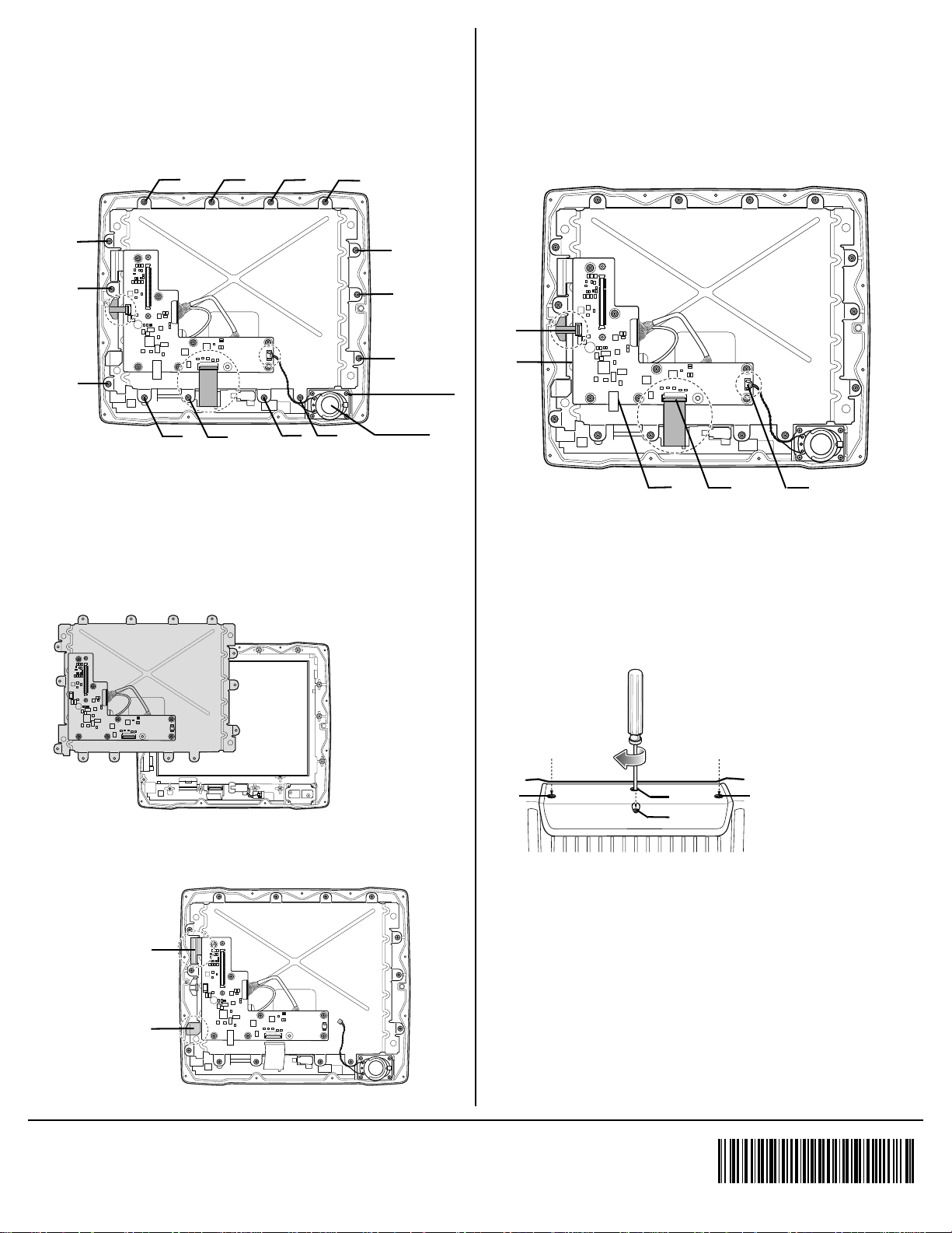
7. Remove the following internal screws:
5
11
8
4
13
14
6
2
12
7
3
1
9
1
Speaker
Screws (four)
Speaker
Use EMI Tape
P/N 51-401112-01
Use EMI Tape
P/N 51-401113-01
a
d
c
e
b
1
4
3
2
•
Remove the fourteen perimeter screws that secure the
display frame to the upper display housing assembly
using a T10 Torx driver.
•
Remove the four speaker screws and speaker using a
T8 Torx driver.
8. Remove the old touchscreen and add the new replacement
touchscreen.
a. Reinstall the display and fasten the fourteen screws.
Torque: 6.0 ±0.3kgf-cm (5 lbs-in)
b. Reinstall the speaker, fasten the four screws.
Torque: 4.0 ±0.2kgf-cm (3.5 lbs-in)
10. Reconnect the following cables to the DTB:
a. FPC connected from TP to DTB.
b. FPC connected from speaker to DTB.
c. FPC connected from keyboard to DTB.
Optional extra heater cables:
d. FPC connected from heater to DTB.
e. Power connected from heater to DTB.
11. Reattach the large FPC between the display and the core.
Using a T10 Torx driver, Torque: 6.0 ±0.3kgf-cm (5 lbs-in).
a. Refasten the thirteen perimeter screws that secure the
display to the core (as shown in Step 2).
9. Install two pieces of EMI tape closely against the edge of
the electrical board and the internal frame.
b. Reassemble the Dome onto the VC80 and refasten the
four dome screws.
Refer to the VC80 User Guide for information on calibrating the
touchscreen.
Zebra and the stylized Zebra head are trademarks of ZIH Corp., registered in many jurisdictions
worldwide. All other trademarks are the property of their respective owners.
© 2016 Symbol Technologies LLC, a subsidiary of Zebra Technologies Corporation. All rights reserved.
MN-002709-01 Rev A 04/2016
 Loading...