

Page 1
Zebra® T300™ Printer
Maintenance Manual
Part # 547001L Rev. 2
Page 2

Zebra® T300 Printer
Maintenance Manual
Revision 2
Registration Form
ZEBRA TECHNOLOGIES CORPORATION
To receive maintenance manual revisions
and updates, complete this form and fax
o r mail it t o Zebra Technologies at th e
fax number or ad dress shown below.
COMPANY
ADDRESS
CITY
STATE, ZIP
PHONE # ( )
CONTACT:
Zebra Technologies Corporation
333 Corpor ate Woods Parkway
Vernon H ills, Illino is 60060-3109 U.S.A.
ATTN: Technical Training Group
Part # 547001L Rev. 2 Page i
FAX Number: +1 (847) 821-1492
Page 3

NOTES
Page ii Part # 547001L Rev. 2
Page 4

Zebra T300 Printer Maintenance Manual
Table of Contents
TABLE OF CONTENTS
INTRODUCTION
................................................................................................................................
IMPORTANT NOTES
SPECIFICATIONS
SETTING UP THE PRINTER AND SOFTWARE
Operating the Printer.......................................................................................................................................................5
Printer Operating Modes.............................................................................................................................................5
Printing Method..........................................................................................................................................................5
Operator Controls........................................................................................................................................................5
Printer Troubleshooting Indicator Lights.....................................................................................................................7
Initial Printer Power-Up ..............................................................................................................................................7
Adjusting for Different Media Widths.........................................................................................................................8
Adju s ting for Di ffe rent Ribbon Widths........................................................................................................................8
Ribbon Loading Procedure..........................................................................................................................................9
Media Loading Procedure..........................................................................................................................................10
Calibration Procedure................................................................................................................................................11
.....................................................................................................................ii
.........................................................................................................................
..............................................................................................................................
............................................................................
1
1
1
5
Setting Up the Software................................................................................................................................................. 12
BAR-ONE System Requirements..............................................................................................................................12
BAR-ONE Installation..............................................................................................................................................12
TROUBLESHOOTING
PREVENTIVE MAINTENANCE PROCEDURES
Lubrication................................................................................................................................................................15
CORRECTIVE MAINTENANCE PROCEDURES
Fine Pr i nthead Adjust ment ............................................................................................................................................16
Platen Roller Replacement.............................................................................................................................................17
Remove the old Platen Roller ....................................................................................................................................17
Install the new Platen Roller......................................................................................................................................18
Ribbon Handler Rep lacem ent.........................................................................................................................................19
Remove the old Ribbon Ha ndle r Assembly................................................................................................................19
Install the new Ribbon Handler Assembly. ................................................................................................................19
Pri nthea d Rep lacement .................................................................................................................................................. 20
Remove the old Printhead..........................................................................................................................................20
Install the new Printhead...........................................................................................................................................21
......................................................................................................................
...........................................................................
..........................................................................
13
15
16
Part # 547001L Rev. 2 Page iii
Page 5

Zebra T300 Printer Maintenance Manual
Replacing the Main Logic Board ...................................................................................................................................22
Remove the old Main Logic Board............................................................................................................................22
Install the new Main Logic Board .............................................................................................................................22
Control Panel Circuit Board Replacement......................................................................................................................24
Remove the old Circuit Board...................................................................................................................................24
Install the new Circuit Board ....................................................................................................................................25
Dri ve Mot or Replacement ..............................................................................................................................................26
Remove the old Drive Motor.....................................................................................................................................26
Install the new Drive Motor......................................................................................................................................27
Media Sensor Harness Assembly Replacement...............................................................................................................28
Remove the old Media Sensor Harness Assembly...................................................................................................... 28
Install the new Media Sensor Harness Assembly.......................................................................................................28
MAIN CIRCUIT BOARD LAYOUT
MECHANICAL DRAWINGS
Replacement Parts.........................................................................................................................................................31
............................................................................................................
.................................................................................................
List of Tables
Table Description
1 Specifications........................................................................................................................................ 1
2 Feed Key Troubleshooting Modes......................................................................................................... 6
3 Printer Troubleshooting Indicator Lights.............................................................................................. 7
4 System Requirements...........................................................................................................................12
5 Troubleshooting Chart.........................................................................................................................13
6 Cleaning Schedule...............................................................................................................................15
7 Replacement Parts ...............................................................................................................................31
8 Maintenance Kits.................................................................................................................................31
30
31
Page iv Part # 547001L Rev. 2
Page 6

Zebra T300 Printer Maintenance Manual
List of Illustrations
Figure Description
1 120 and 230 VAC Power Line Cords .................................................................................................... 4
2 Examples of International Safety Organizations Symbols...................................................................... 4
3 Operator Controls................................................................................................................................. 5
4 Configuration Label (Sample) ............................................................................................................... 6
5 Adjusting for Different Media Widths...................................................................................................8
6 Adju s ting for Di ffe rent Ribbon Widths.................................................................................................. 8
7 Ribbon Loading Di agram...................................................................................................................... 9
8 Media Loading Diagram..................................................................................................................... 10
9 Media Sensor Profile (Profile).............................................................................................................11
10 Disassembling and Cleanin g of the Ribbon Supply and Take-up Spindles ........................................... 14
11 Fine Printhead Adjustment..................................................................................................................16
12 Installation and Removal of the Platen Roller...................................................................................... 17
13 Cover Removal and Electrical Connector Location.............................................................................. 18
14 Ribbon Handler Assembly Replacement .............................................................................................. 19
15 Removal of the Printhead Cable and Screw.........................................................................................20
16 Main Logic Board Removal/Reinstall..................................................................................................23
17 Tower Enclosure Removal................................................................................................................... 24
18 Control Panel Circuit Board Installation ....................................................................................... ...... 25
19 Drive Motor Replacement...................................................................................................................26
20 Removal of the Media Sensor Harness Assembly................................................................................. 29
21 Main Circuit Board Layout ................................................................................................................. 30
22 Media Support Kit .............................................................................................................................. 32
23 Cutter Module Kit............................................................................................................................... 32
24 Media Guide Kit.................................................................................................................................33
25 Ribbon Out Se nsor Assembly Kit ........................................................................................................ 33
All trademarks are the property of their respective owners. Zebra is a registered trademark of Zebra Technologies
Corporation.
© 1997 Zebra Technologies Corporation. All rights reserved.
Part # 547001L Rev. 2 Page v
Page 7

Zebra T300 Printer Maintenance Manual
NOTES
Page vi Part # 547001L Rev. 2
Page 8
Zebra T300 Printer Maintenance Manual
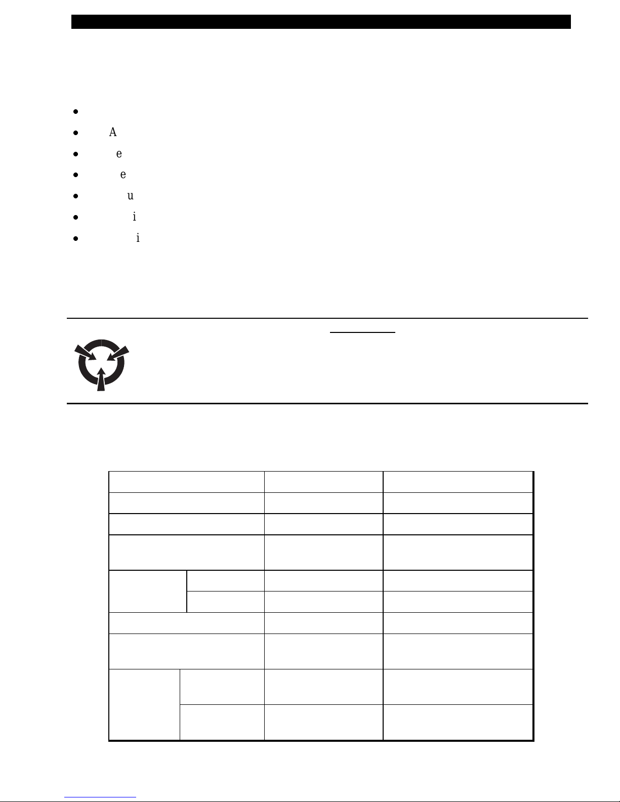
INTR ODUCTION
For information on any of the following topics, please refer to t he T300 User’s Guide:
x
Unpacking and inspection
x
Additional requirements
x
Setting up the printer and software
x
Preventive maintenance
x
Troubleshooting
x
Specifications
x
Additional information specific to particular configurations of the T300 printer.
IMPORTANT NOTES
Any maintenance performed by unauthorized personnel on a T300 printer voids the warranty.
WARNING:
DANGER OF ELECTRICAL SHOCK IF POWER SUPPLY IS DISASSEM BLED!
THERE ARE NO SERVICEABLE COMPONENTS INSIDE THE POWER
SUPPLY. SERIOUS SHOCK HAZARDS ARE PRESENT INSIDE THE POWER
SUPPLY CASE, EVEN WITH TH E PO WER S W ITCH OFF.
SPECIFICATIONS
Table 1. Specifications
Print density 203 dots/inch 8 dots/mm
Print width 1 to 4.125 inches 25.4 mm to 104.0 mm
Print Speed 2 in/sec., 1.5 in/sec. 50 mm/sec, 38 mm/sec
Label width (including
backing material, if any)
Label length Tear off 0.50 to 18 in. 12 mm to 457 mm
Cutoff/Peel 1 to 18 in. 25.4 mm to 457 mm
1.0 in to 4.65 in. 25.4mm to 118 mm
Interlabel gap 0.08 to 0. 16 in. 2 mm to 4 mm
Label t hickness (includ ing
backing material, if any)
La bel roll Ma x. outer
diameter
Size Min. inner
core diameter
Part # 547001L Rev. 2 Page 1
0.003 to . 010 in. 0.076 mm to 0.25 mm
4.0 in. 101 mm
1.0 in. 25.4 mm
Page 9
Zebra T300 Printer Maintenance Manual
Registration Horizontal ± 0.059 in. ± 1.5 mm
tollerance Vertical ± 0.0393 in. ± 1.0 mm
Inter-label gap .08 in to .16 in. 2 mm to 4 mm
First dot location (from outer
0.060 to 0. 140 1.5 mm to 3.5 mm
media edge)
Ribbon r oll
size
Max. outer
diameter
Min. inner c ore
1.5 in. 38 mm
0.50 in. 13.0 mm
diameter
Max. Length/Ribbon Roll 360 ft. 110 mm
Ribbon Mar. Width/Roll 1.0 in. to 4.25 in. 25.4 mm to 108 mm
Physical size (LxWxH) 10.1 x 8.8 x 6.2
256mm x 223mm x 157mm
in.
Weight (without media) 7 lbs 3.18 kg
Shipping Weight 10 lbs 4.54 kg
Temperature Operating 40° to 100° F 4° to 38° C
range Storage -4° to 140° F -20° to 60° C
Re lat iv e humidit y, o peration and
10 to 90% non c ondensing
sto rage
Media requirements Zebra recommends using Zebra-brand thermal transfer media
that is outside-wound (the label or printing surface is wound
on the out side of the backing). Media may be roll or fanfold,
transmissive or reflective (black-mark) sensing; continuous,
die-cut or not ched.
Notched media:
notch must be 1/4 inch wide x 3/32 inch
long located on the left side of the label as viewed from the
front of the printer.
Black-mark media:
marks must be located w ithin 1 mm o f
the left edge of the media as viewed from the front of the
printer;
Mark thickness: 0.12 - 0.43 inches (3 mm - 11 mm);
Mark width: 0.43 inches (11 mm) - full media width; mark-
to-mark leading edge registration tolerance ±0.016 inch (± 0.4
mm);
Mark density >1.0 ODU (Optical Density Unit);
Ma ximum density of th e back of the media on wh ich the
black mark is printed: 0.5 ODU.
Page 2 Part # 547001L Rev. 2
Page 10
Zebra T300 Printer Maintenance Manual
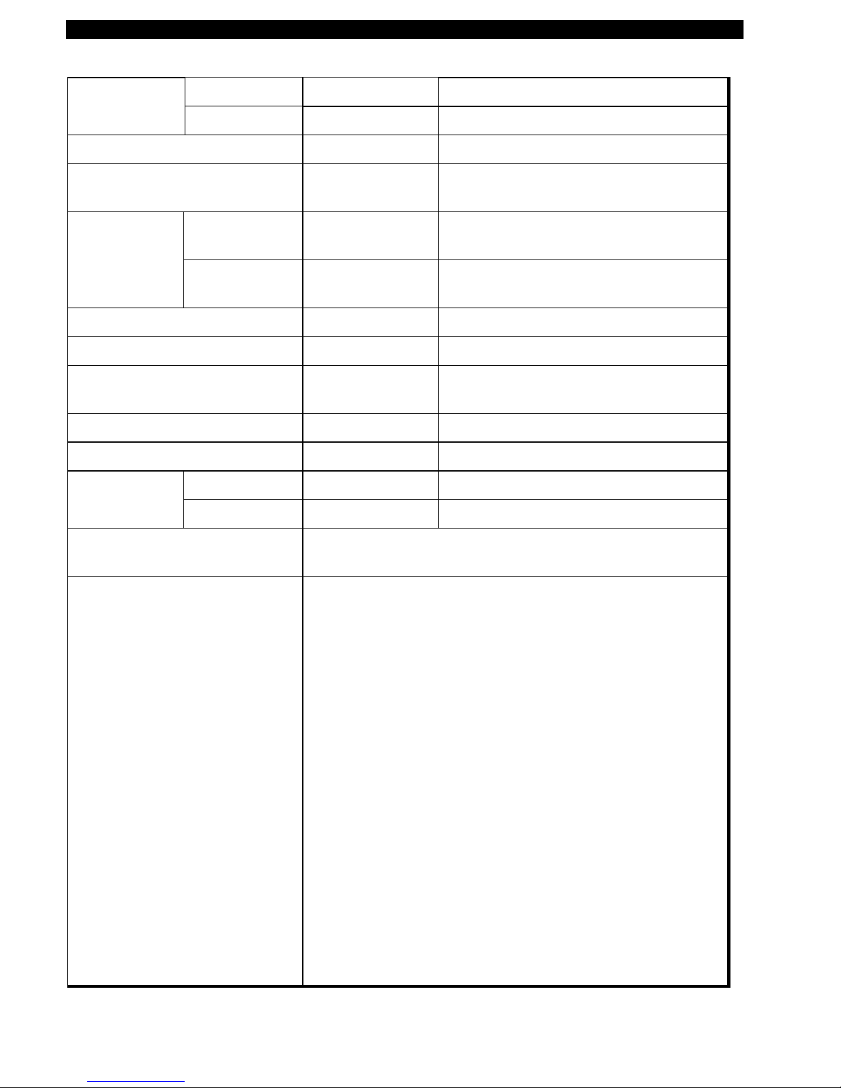
Ribbon r equirements Zebra recommends use of Zebra-brand ribbon which is
inked on the inside surface. (Use tape to see which
side is inked.)
Fonts available
Bar codes available
x
CG Triumvirate Bold Condensed (6, 8, 10, 12, 14,
18 pt)
x
Zebra fonts A, B, C, D, E (OCR-B), F, G, H
(OCR-A), IBM® Code Page 850 (International
Characters, Gr aphics symbols)
x
Codabar (supports
ratios of 2:1 to 3:1)
x
Code 11
x
Code 128 (support s
se rialization in all
subsets and UCC
Case Codes)
x
Code 39 (support s
ratios of 2:1 to 3:1)
x
Code 93
x
EAN Version 8 and
13, EAN
Extensions
x
Industrial 2 of 5,
x
Interleaved 2 of 5
(supports rat ios of 2:1 to
3:1, Modulus 10 Check
Digit)
x
LOGMARS
x
MaxiCode
x
PDF 417
x
MSI
x
Plessey
x
POSTNET
x
UPC Versions A and E,
UPC Extens ions with 2
and 5 digit supplements.
Standard 2 of 5
Electrical External 120 or 230 VAC power supply, depending on
which model you order. Additional custom line cords
may also be available.
Communications 36-pin Centronics® compatib le pa rallel port; 9-pin RS-
232 serial port
Processor 32-bit microprocessor, 512 K Ram
Seria l data cable Sh ould us e twisted shielded pairs, not lo nger than 6 ft
(1.8 mm) a s recommend ed in the Appendix of the
TIA/EIA-485 Specification
Para llel da ta cable For maximum reliability, us e a p arallel data ca ble no
longer than 6 ft (1.8 mm)
Part # 547001L Rev. 2 Page 3
Page 11
Zebra T300 Printer Maintenance Manual
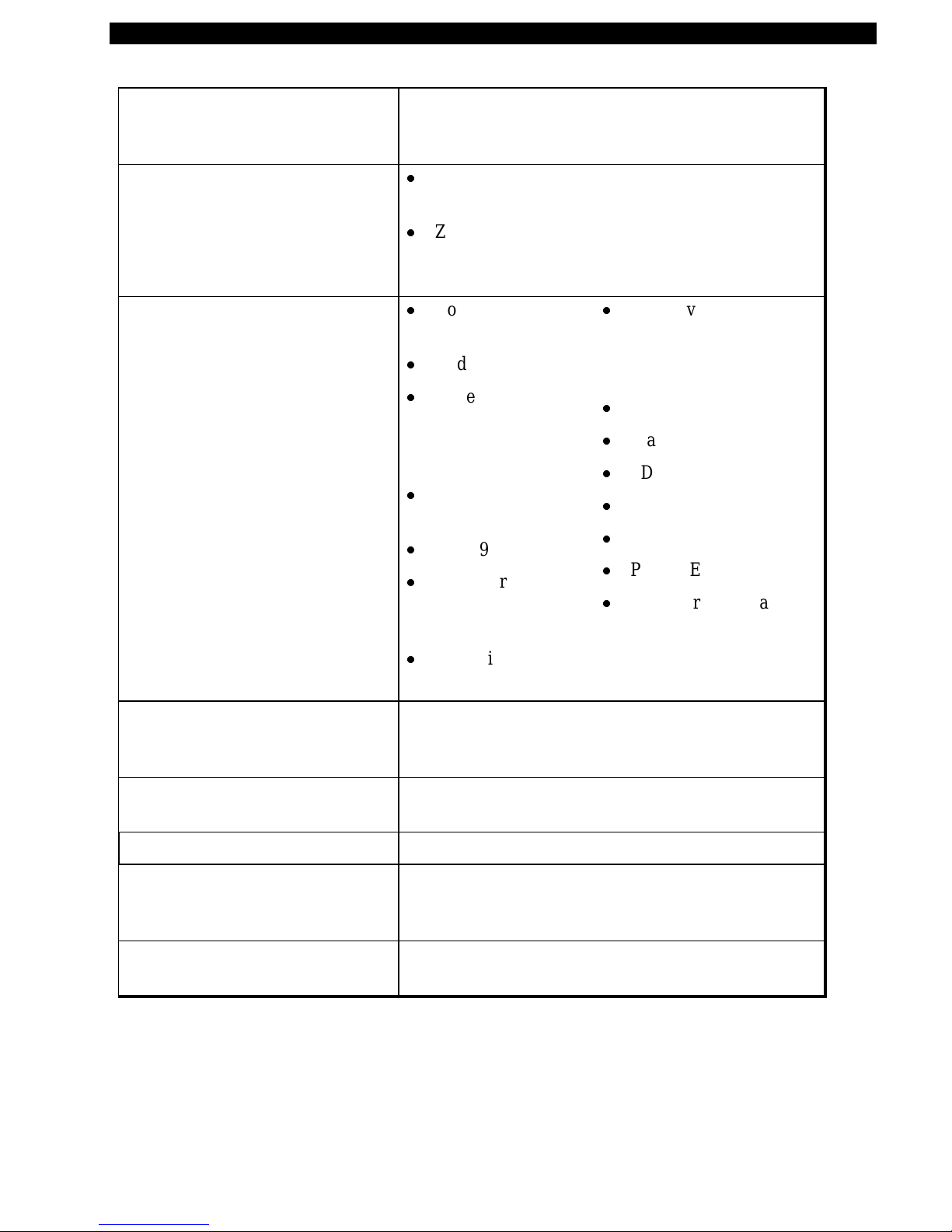
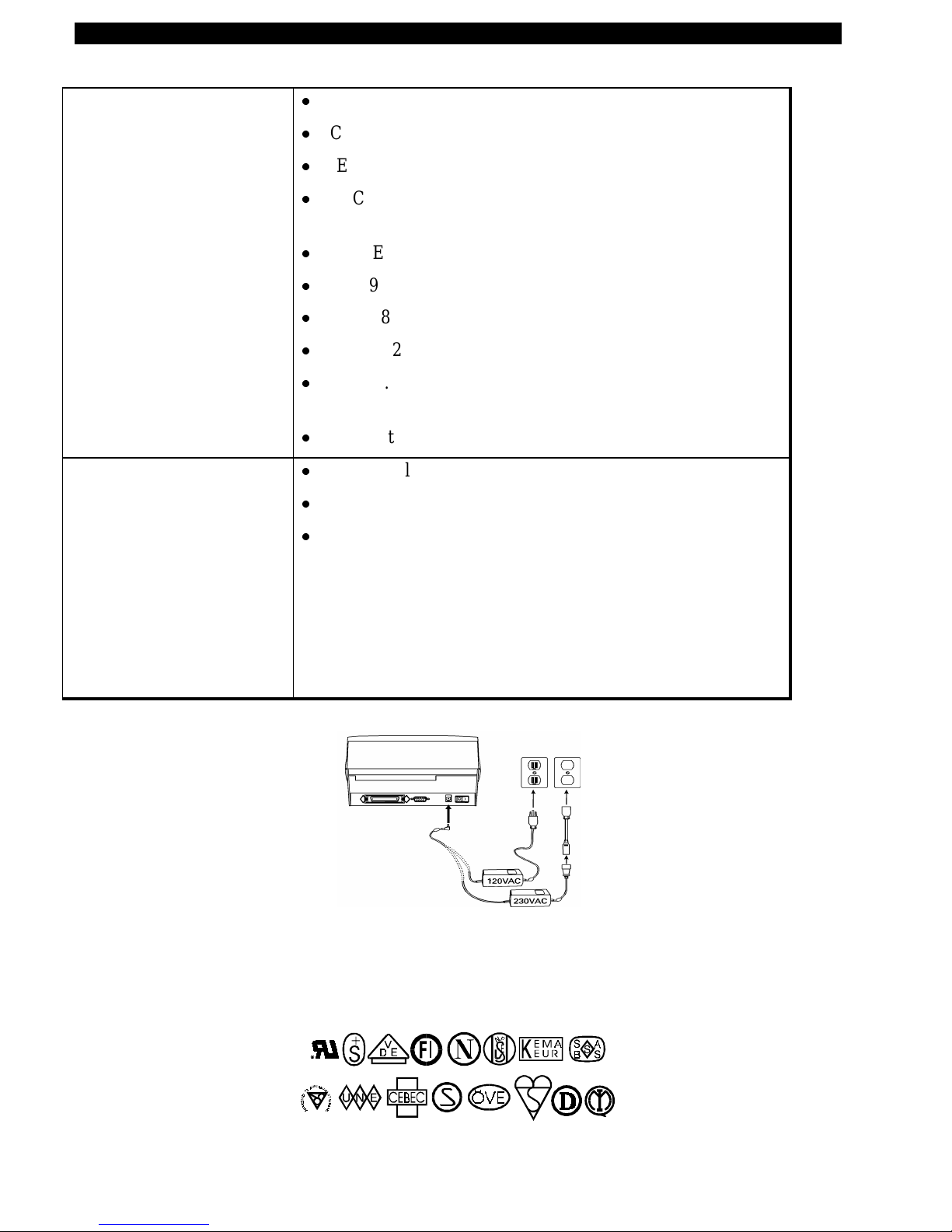
Agency approvals
Power line cord
x
UL 544 Medical Equipment Standard Part 42.5
x
CSA 22.2 No. 950 Canadian Safety Standard
x
IEC 950/EN 60950 International Safety Standard
x
FCC Part 15 Subpart B Level A Electro magnetic Radiation
Standard
x
AAME Medical Standard part 4.3. 2
x
UL 1950 Domestic Safety Standard
x
SOR/88-475 Canadian Electromagnetic Radiation Standard
x
EN50082-1 International Immunity Standard
x
C.I.S. P . R. -22 Class B European Electromagnetic Radiation
Standard
x
Ca rries the CE ma rk of compliance
x
Th e overall length must be less than 12.5 ft (3.8 meter s)
x
It must be rated for a least 3A, 250V.
x
The chassis ground (earth) MUST be connected t o assure
safety and reduce electromagnetic interference. The ground
connection is handled by the third wire (earth) in the power
line cord. (See Figure 1.)
The AC power plug and IEC 320 connector must bear the
certification mark of at least one international safety
organization. (See Figure 2.)
Figure 1. 120 and 230 VAC Power Line Cords
Figure 2. Examples of International Safety Organizations Symbols
Page 4 Part # 547001L Rev. 2
Page 12
Zebra T300 Printer Maintenance Manual
SETTING UP THE PRINTER AND SOFTWARE
Operating the Printer
To create a label for the Zebra T300, you may either use the BAR-ONE® software t o create the label
format or write o ne in ZPL II®, which is Zebra’s pro gramming language for crea ting labe ls. If you are
using BAR-ONE® software, refer to the BAR-ONE help files (us_man.exe). If you are using, or plan
t o use the ZPL II programming language to for mat your labels, make su re you h ave a copy of th e
II Programming Guide
Printer Operating Modes
x
Tear-Off Mode.
x
Peel-Off Mode.
waits until t he o perator remov es the label, then the n ext labe l is print ed.
x
Cutter Mode.
cut automatically af ter it is print ed.
(Zebra PN 46469L).
The operator tears off a single label (or a strip of labels) after printing.
The backing material is peeled away from the label as it is printed, the printer
(A vailab le only with factory in stalled Optio nal Cutter Module. ) Each label is
ZPL
Printing Method
Thermal Transfer.
onto the media to form an image.
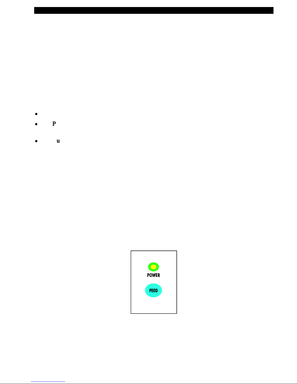
Operator Controls (See Figure 3)
Power Switch.
connecting or disconnecting an y cables
Feed Key.
the printer to feed a blank label. The Feed Key also activates a number of specialized functions that
are described in Table 2.
In normal u se, pr essin g t he Fe ed Key once when the pr inter is idle (no t p rinting) will c aus e
(Requires use of thermal transfer ribbon.) The printer t r ansfers ink from a ribbon
Located o n t he rear of the printer
.
. The power switch should b e t u rned off before
Part # 547001L Rev. 2 Page 5
Figure 3. Operator Controls
Page 13

Zebra T300 Printer Maintenance Manual
Table 2: Feed Key Troubleshooting Modes
Power Off Mode (Communications Diagnostics Mode)
With the printer power off, press and hold the Feed key while you turn the power on. The
printer prin ts out a listing of its current configu ratio n (configuration label). ( See Figure 4.)
For best results, use media that is at least 4 inches wide by 4 inches long. After printing the
label, the prin ter will automatically enter a diag nos tic mode in wh ich the printer print s out a
literal representation of all data subsequently received (communications diagnostics). To
exit this mode , t urn the prin ter power off.
Power On Modes
With the printer powered on, printhead closed, and Power light on, press and hold the Feed
key for sev eral seconds a n d t h e Power Light will begin t o step th ro ugh a series of flash
sequences. Each sequence consists of a different number of flashes as shown in the
following table. The correspo nding explanation indicates what happens when you release
the Feed key after each flash sequence.
Sequence Number of
Results
flashes
1 1 The label sho wing the curre nt con figuration of the printer is
printed. For best results, use media that is at least 4 inches wide
by 4 inches long. (See Figure 4.)
2 2 The media sensor calibration process is started (see calibration
procedure).
3 3 The serial commu nication parameters are reset to 9600 baud, 8
bit word length, no parity and 1 st op bit
4 4 Reset the printer to factory defaults. Once this mode is entered,
t he Power light will flas h rapidly. Press and release th e Feed k ey
one more time and the factory default values are saved into
memory.
Figure 4. Configuration Label (Sample)
Page 6 Part # 547001L Rev. 2
Page 14

Zebra T300 Printer Maintenance Manual
Printer Troubleshooting Indicator Lights.
Table 3: Printer Troubleshooting Indicator Lights
Power Light Printer Condition
Off Power is off or printer not r eceiving power
On Power is on
Flashes once
every 3 seconds
Printer failed internal diagno stics. Call a
Service Technician.
after power-up
x
Paper out or not sensed
x
Ribbon out
Flashing
x
Needs calibration
x
Printhead is over temperature
x
Cutter error
Initial Printer Power-Up
Turn the pr inter on by toggling the P ower Switch on the rea r o f the pr inter. The Powe r ligh t will tu rn
on. The printer performs a set of internal diagnostics, and after the diagnostics have been completed
(within 1-10 s e conds), the motor may sta rt briefly.
If loading the printer with media for the first time or if you are changing the type of media you’re
using, perform the calibration procedures (see calibration procedure).
Part # 547001L Rev. 2 Page 7
Page 15

Zebra T300 Printer Maintenance Manual
Adjusting for Different Media Widths
The thumbwheel on the side of the Printhead allows the Printhead pressure to be adjusted. To adjust,
rot ate the thumbwheel in a clockwise direction to reduce the pressure o n t he right edge of the
Printhead. If the right edge printing seems to be too light, then rotate the thumbwheel slightly
counte rclockwise to achieve unifor m prin t quality across the label. (See Figure 5.)
Figure 5. Adjusting for Different Media Widths
Adjusting for Different Ribbon Widths
Refer to Figu re 6. If you are using narrow ribbon, hold the r ibbon spindle while turning the ribbon
t ension adjustment knob clockwise. For full-width ribbon, turn t he knob counter -clockwise until it
reaches the stop . I f your ribbon is somewhere in-between, experiment until you achieve acceptable
print quality.
Figure 6. Adjusting for Different Ribbon Widths
Page 8 Part # 547001L Rev. 2
Page 16
Zebra T300 Printer Maintenance Manual
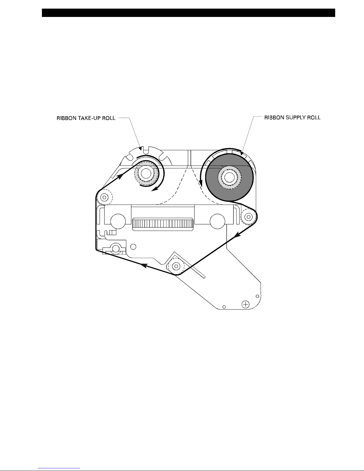
Ribbon Loading Procedure (See Figure 7)
Part # 547001L Rev. 2 Page 9
Figure 7. Ribbon Loading Diagram
Page 17
Zebra T300 Printer Maintenance Manual
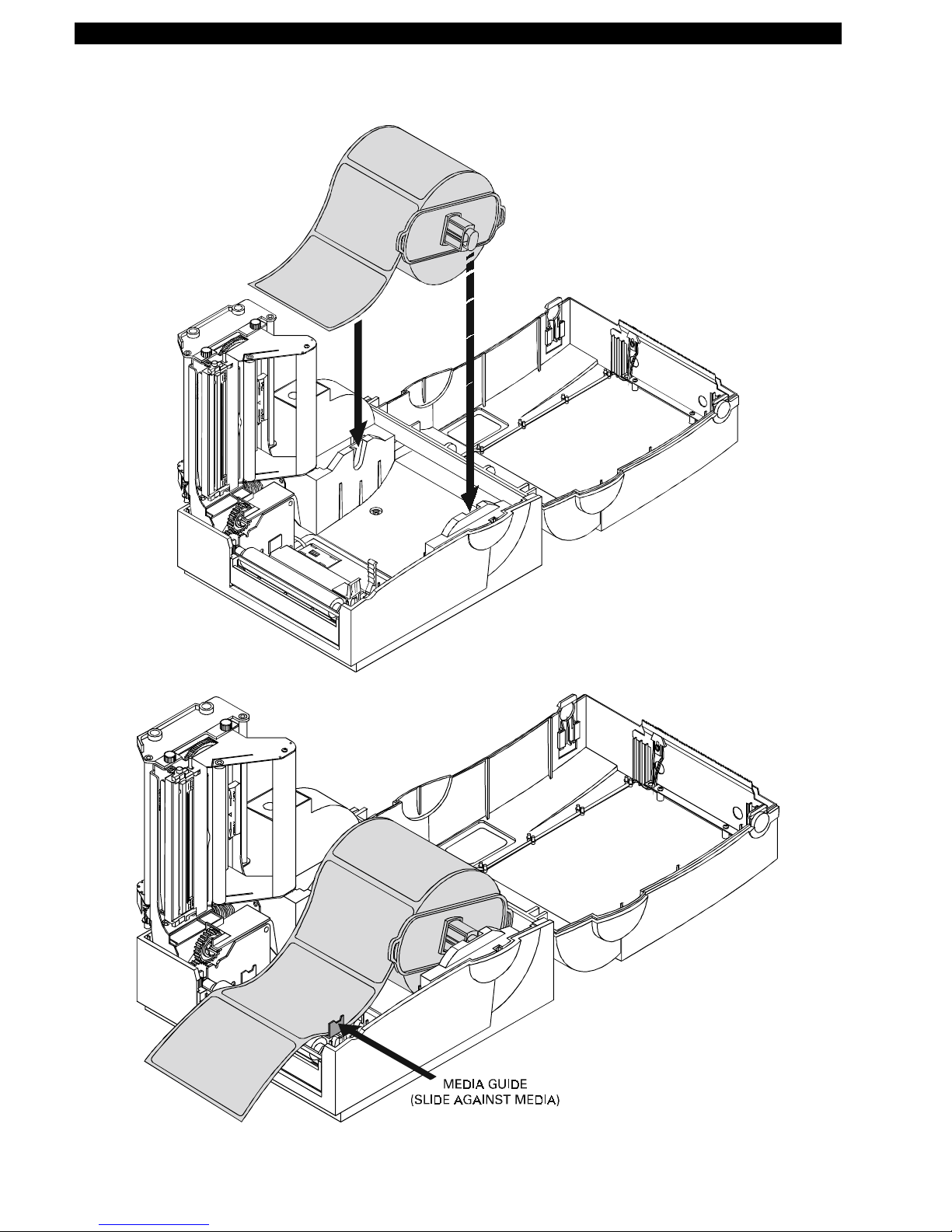
Media Loading Procedure (See Figure 8)
Figure 8. Media Loading Diagram
Page 10 Part # 547001L Rev. 2
Page 18
Zebra T300 Printer Maintenance Manual
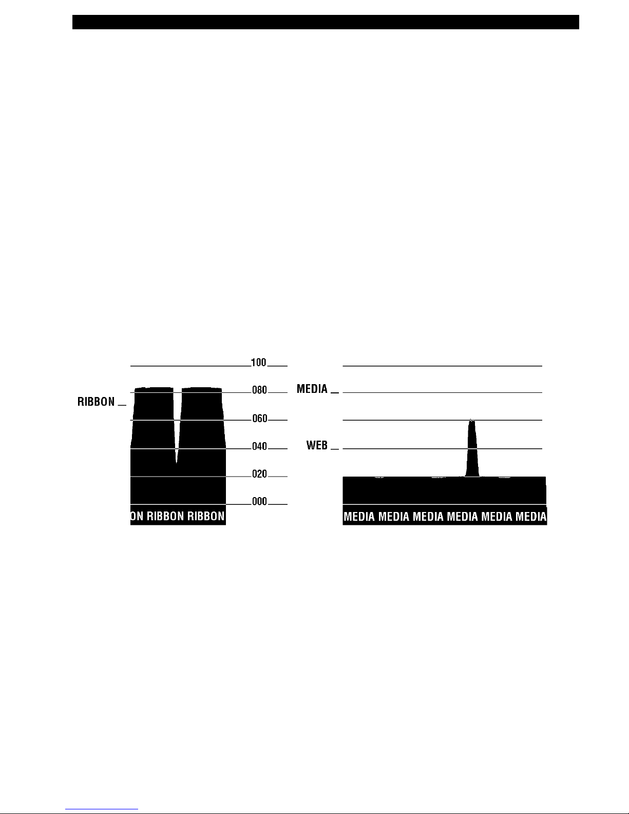
Calibration Procedure
This calibration procedure should be performed the first time you use the printer and any time you
change the type of media in t he printer.
1.
2.
Turn the pr inter p ower on if it is not already on.
Re move sev eral labe ls from a s ection of b ack ing material s o that o nly th e backing mater ial is
under the printhead mechanism and media sensor .
3.
Pres s and ho ld the Feed K ey until the Power light flash es twic e in a row. (Fir st it will flash
once, then twice in a row at which point you release the key.)
4.
The printer will adjust the me dia s ensor level for the media backing you are using. After it is
done making t his adjustment, the Power light will flas h rapidly.
5.
6.
Reload the media so that a label is under the printhead and over the media sensor.
Pres s and re lease the Feed K ey. A profile of the media sens or settings will print. See Figure 9.
When comple te, the p rinter will save the new settin gs in memory and the printer is read y for
normal operation.
Part # 547001L Rev. 2 Page 11
Figure 9. Media Sensor Profile (Sample)
Page 19
Zebra T300 Printer Maintenance Manual
Setting Up the Software
Note:
If you plan to use BAR-O NE s oftwa re to create your labels, you w ill need to ins tall the
software on you computer before you can operat e your printer.
You will not need to use BAR-ONE s oftware if you a re printing label formats cr eated in ZPL II. To
print ZPL II, you may use practic ally any tex t p ro gram on any comp uter tha t w ill send ASCII text to
the printer via either the serial or parallel port. For more information, refer to the
Programming Guide
(Zebra PN 46469L).
BAR-ONE System Requirements
BAR-ONE software works with most IBM compatible per sonal computers available today. The
software may b e installed an d up-and- running w ithin a few minutes. Re fer to the on-line help syst em
and to the Read-Me file for further information and/or last-minute updates. The BAR-ONE software
may be installed on any personal computer that meets the system requirements in Table 4:
Table 4. System Requirements
BAR-ONE Software Minimum Recommended
ZPL II
Processor 486SX 486DX
Hard disk 3 MB 10 MB
Memory 4 MB RAM 8MB RAM
Interface RS-232 Parallel
Display VGA SVGA
Floppy drive 3-1/2 Inch
Operating system Windows™ 3.1 or higher, NT,
95; OS/2.2.1 or later
Mouse RS-232 or PS/2
BAR-ONE Installation
The Zebra T300 printer uses the Windows™ based BAR-ONE software or ZPL II Pro gr amming
La nguage commands. To install BAR -ONE software:
1.
2.
3.
Start Windows.
Insert disk 1 of the BAR-ONE software in your floppy disk drive (A: or B:).
In Program Manager, click on the
from th e
Start
menu.)
File
menu. Select
Run
. (Windows 95 users: select
Run
4.
5.
Page 12 Part # 547001L Rev. 2
Type
A:\SETUP
B:\SETUP
(or
Follow the o n-screen instructions to complete the installa tion.
) and then press OK.
Page 20

Zebra T300 Printer Maintenance Manual
TROUBLESHOOTING
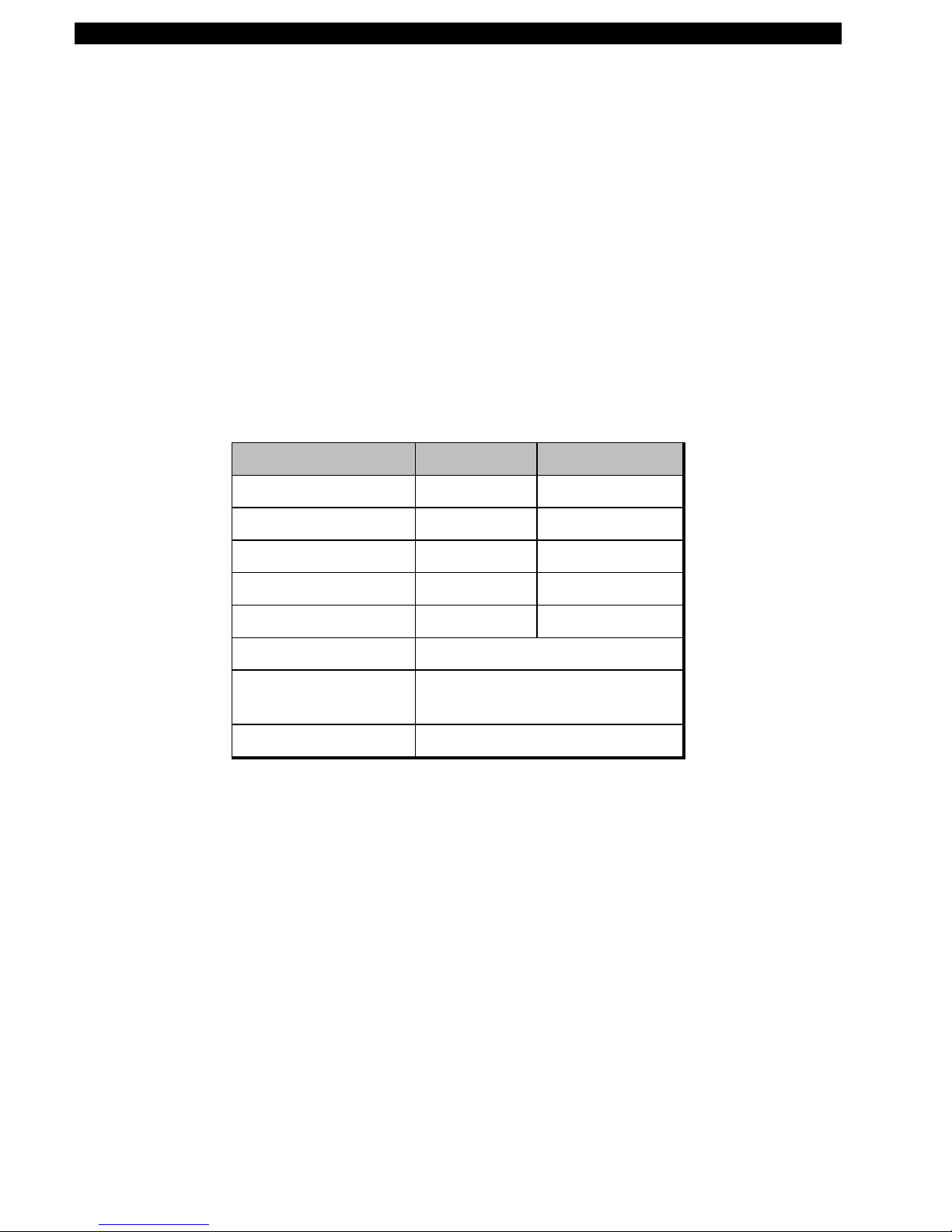
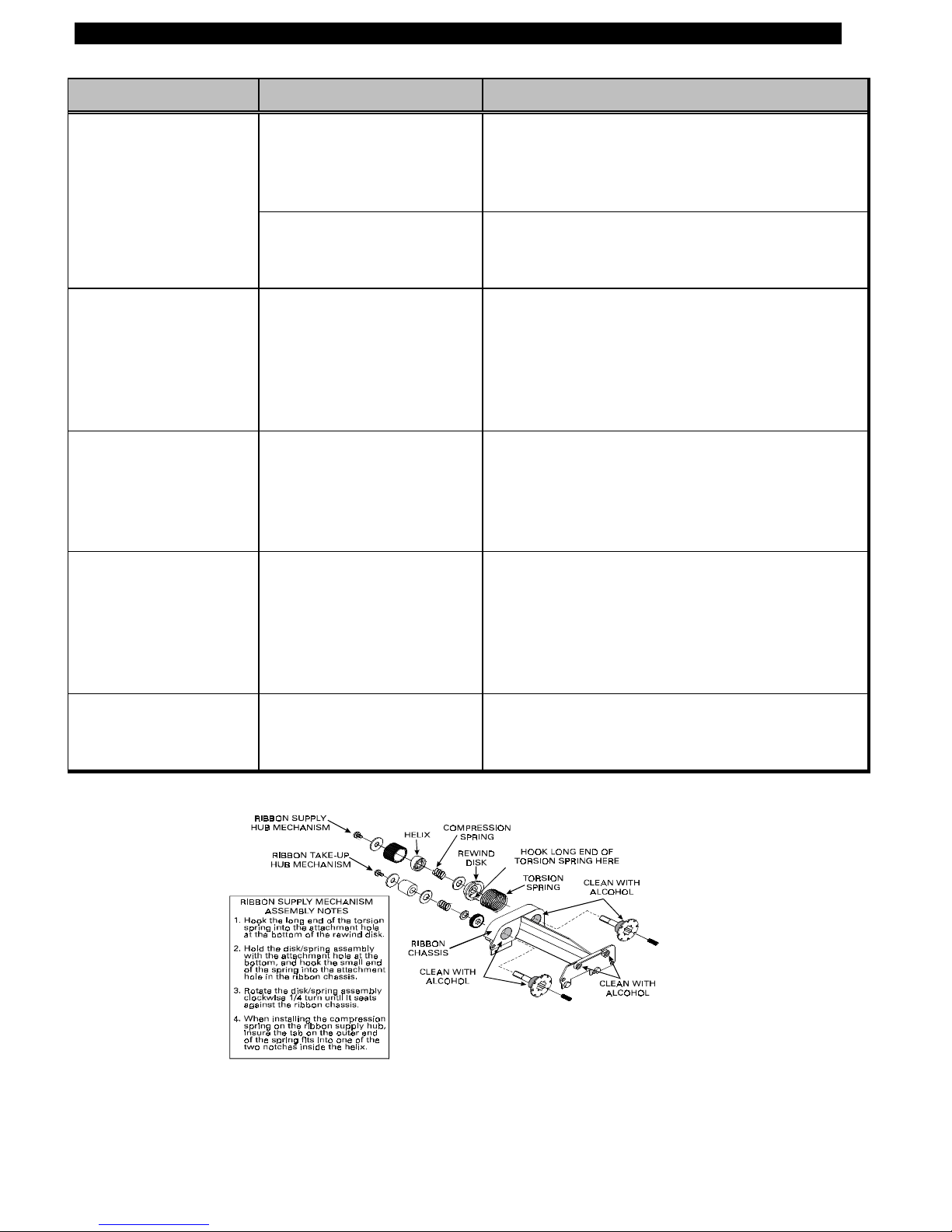
Table 5. Troubleshooting Chart
SYMPTOM DIAGNOSIS ACTION
Po wer light does not
turn on when Power
sw itc h is turn ed on.
Whe n pr in ter is first
powered on, t he Power
light flashes every 3
seconds.
Po wer light is flashing.
For more information,
see Table 3.
Long tracks of missing
print (blank vertical
lines) on several la bels.
Printer is not receiving
power.
Make sure that the power supply is plugged into
the printer and into a wall outlet, power st rip, or
other source of power.
Printer Failed an in ternal
Turn printer off and then back on.
diagnostic test .
Out of media/ribbon or
media/ribbon incorrectly
loaded.
Load media correctly. Make sur e that the media
is placed to t he left edge of the platen roller and
that it feeds under the Printhead, otherwise, it
may not be detected by the media sensor.
Printhea d is overheated. Allo w print er to cool. Pr inting resumes
automatically when the Printhead cools to
operat ing temperature.
Needs calibra tion Ca librate the pr inter (see Calibration procedures).
Cutter (optional) error. Clean the cutter.
Printhead is dirty. Clean the Printhead. (See Table 6.)
Print element is damaged. Call a service technician to r eplace the Printhead.
Poor p rint quality. Printhead is dirty. Clean the P rinthead. (See Table 6.)
Ribbon tension is not set
correct ly.
Change the ribbon tension knob to t he ot her
se tting. Ge n erally, set it clockwise for narrow
ribbon a nd cou nter-clockwise for wid e ribbon.
Media Width adjustment
incorrect.
Adjust the media width thumbwheel on the side
of the printhead (see adjusting for different media
widths, figure 5).
Mis-registration
(location of printed
Printer needs to be
calibrated.
Recalibrate the printer. (See Calibration
procedure).
information changes on
t he lab el, from label to
label).
Ribbon tension is not set
correct ly
Change the ribbon tension knob to t he ot her
se tting. Ge n erally, set it clockwise for narrow
ribbon a nd cou nter-clockwise for wid e ribbon.
Part # 547001L Rev. 2 Page 13
Page 21
Zebra T300 Printer Maintenance Manual
SYMPTOM DIAGNOSIS ACTION
A lab el format wa s
sent to the printer but
Communications
parameters are incorrect.
not reco gnized.
Problem with the data
cable.
Ribbon Wrinkle Print head Pressur e
Misadjusted
In the Peel Mode, liner
Liner is slipp ing Open the Peel-off Lever. Pull the liner until it is
bulges out from the
Peel Bar and may
block the Label
Present Sensor .
Ribbon T ake-U p
Spindle rotation is not
smooth and c onsiste nt.
Dirt build-up on the R ibbon
Supply and Ribbon Take-
Up Spindle Hubs.
Ribbon may exit
printer still bonded to
t he lab el.
For serial communication, make sure that the
baud rates of the printer and the computer match.
Also, make sure that the correct com port o n t he
PC is connected to the printer.
Make sure the data cable is installed correct ly.
For serial operation, make sure you are using a
“null modem” cable.
Rotate the Printhead Pressure Adjustment
Thumbw heel until wr inkle is eliminated. (Light
print will r esult if the Thumbwhe el is turned too
far) . Change ribbon te ns ion setting if pro blem
persists. A fine printhead adjus tment may be
required (see Figure 11).
re-tensioned against the Peel Bar. Close the
Peel-Off Lever.
Refer to Figure 10 and disassemble the Ribbon
Supply and Ribbon Take-up Hub mechanisms.
Clean the indicated areas with swabs saturat ed
with 70% Isopropyl Alcohol (see Table 6).
Printer appears to
operat e, but nothing
prints.
Figure 10. Disassembling and Cleaning of the Ribbon Supply and Take-up Spindles
Ribbon is wound the wrong
way.
Use Zebra-brand ribbon that is wound with t he
ink/wax on the inside surface.
Page 14 Part # 547001L Rev. 2
Page 22

Zebra T300 Printer Maintenance Manual
PREVENTIVE MAINTENANCE PROCEDURES
Table 6. Cleaning Schedule
AREA METHOD INTERVAL
Printhead
Platen Roller With the power t ur ned off, rot ate the platen roller and clean it
Peel-Off Roller Rotate the peel-off roller and clean it thor oughly with solvent*
Media Path Solvent* and cotton swabs
Peel/Tear Bar Solvent* and cotton swabs As needed.
Media Sensor Air blow Monthly (or
Spindles Take apart and clean with solvent* As needed.
Ribbon Handler
Assembly
Note:
You do not need to turn the printer off prior to cleaning
the Printhead. Use solvent* on a cotton swab to clean the print
elements from end to end. ( T he print elements are the thin gray
line on the Printhead). (See Figure 12.)
thoroughly with solvent* and a cotton swab or a clean lint-free
cloth.
and a cott on swab or a clean lint-free cloth.
Take apart and clean with solvent* and cotton swabs (See
Figure 10).
After every
roll of media
(or 500 ft. of
fanfold
media).
depending on
environment
conditions).
As needed
(or
depending on
environment
conditions).
Exterior Mild detergent or desktop cleaner. As needed.
Interior Brush/vacuum cleaner As needed.
*Z ebr a recommend s us ing solve n t c ontaining 70% isopropyl a lcoh ol, 30% distilled water. Zebra
also recommends using Part Number 01429 Preventive Maintenance Cleaning Kit.
Lubrication
NO LUBRICATING AGENTS OF ANY KIND SHOULD BE USED ON THIS PRINTER! IF
USED, SOME COMM ERCIALLY AVAILABLE LUB RICANTS WILL DAMAGE THE FINISH
AND THE MECHANICAL PARTS.
Part # 547001L Rev. 2 Page 15
CAUTION:
Page 23
Zebra T300 Printer Maintenance Manual
CORRECTIVE MAINTENANCE PROCEDURES
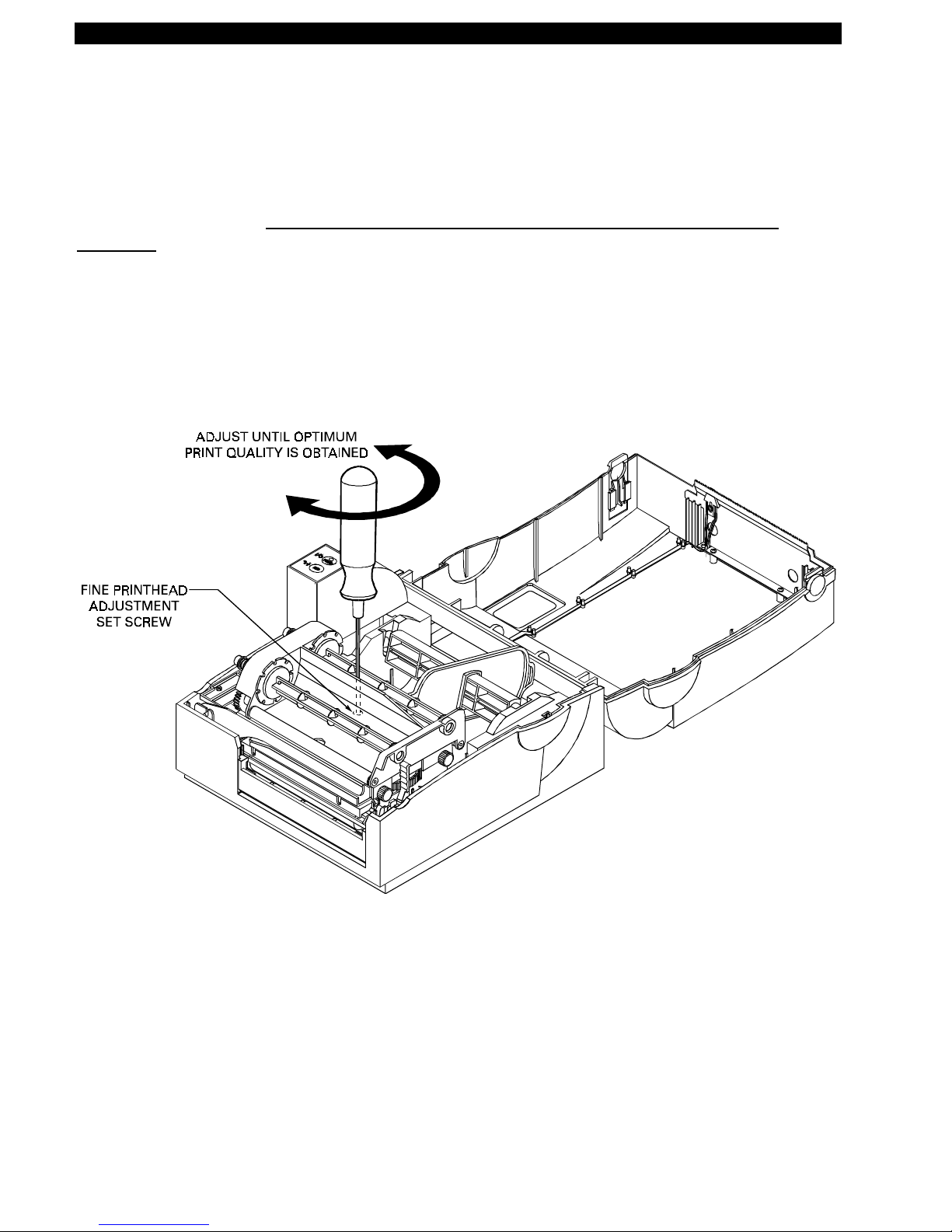
Fine Printhead Adjustment
An Allen set screw is located on top of the Printhead Carrier Assembly that can be adjusted for
controlling prin t quality.
adjusting.
may be necessar y. To adjust the Prin thead, remove tur n the se t screw until optimum print quality is
obtained. Some trial and error may be necessary (see Figure 11).
However, due to a wide variety of media and ribbon that is available, some adjustment
This adjustment is set at the factory and should not need further
Figure 11. Fine Printhead Adju stment
Page 16 Part # 547001L Rev. 2
Page 24

Zebra T300 Printer Maintenance Manual
Platen Roller Replacement
(Use Maintenance Kit PN 503011M)
Remove the old Platen Roller (see Figure 12)
1.
2.
Turn the printer power o ff and disconnect the power cord from the back of the printer.
Open the printer’s top cover and unlatch the Printhead Assembly by pushing back on the
Printhead Release Lever. Remove all media and ribbon from the printer.
3.
Remove the four screws securing the Printhead Assembly and the Media Guide to the printer.
Remove the Media Guid e. ( see Figure 13).
4.
Loosen and remove the three hex screws that secure the Tower Enclosure to the printer. Slide
the Tower E nclosure forward and tilt up to unplug the Control Panel connector from J0004
connector located on the Main Logic Board. Remove the To wer E nclosure.
5.
Loosen and remove the screw securing the ground wire to t he Main Logic Board. Remove all
other connectors from the Main Logic Board. Lift out the Printhead Assembly from the
printer.
6.
Re move the C- Rings (see Figure 12) and w hile pulling slightly fo rward on the Pee l-Off Release
lever, remove the outside bushing from the Platen Roller Shaft. Slide the Platen Roller shaft
out from the gear end and remove the roller.
GEAR ASSEM BLY
Figure 12. Installation and Removal of the Platen Roller
Part # 547001L Rev. 2 Page 17
Page 25

Zebra T300 Printer Maintenance Manual
Figure 13. Cover Removal and Electrical Connector Location
Install the new Platen Roller
1.
While holding the Gear Assembly in place, slide the Platen Roller shaft into the gear assembly.
While pulling slig htly forwar d on the Pe el-Off Release lever, replace the outside bushing and
the ot her shaft end and secure in place with the C-Rings (see Figure 12).
2.
Place the Printhead Assembly back int o the printer. Reconnect all cables (including the ground
wire) to t he Main Logic Board (see Figure 13 for prop er r econnection of connectors).
3.
Reconnect the Cont r ol Panel connector to the Main Logic Board. Lower the Tower Enclosure
back into position on the printer and secure using the three hex screws.
4.
Replace the Media Guide and secure using previously removed hardware. Secure the
Printhea d Assembly using previo usly removed har dwa re.
5.
Replace Media and Ribbon back into the printer, close the cover and reconnect po wer to the
printer.
6.
Turn the power o n and print a configuration label (see Table 2 Power Off Mode
(Communications Diagnostics Mode)).
Page 18 Part # 547001L Rev. 2
Page 26

Zebra T300 Printer Maintenance Manual
Ribbon Handler Replacement
Remove the old Ribbon Handler Assembly
1.
2.
3.
4.
Turn the printer power o ff and disconnect the power cord from the back of the printer.
Open the printer’s top cover and unlatch the Printhead Assembly by pushing back on the
Printhead Release Lever. Remove all media and ribbon from the printer.
Remove the two thumbscrews on the side of the Printhead Assembly. Disconnect the Ribbon
Sensor connector fro m the sensor (see Figure 14).
While holding the ribbon handler asse mbly, pu s h up the right side (where the thumbscrews
have been removed) and slide the assembly towards the left of the Printhead Assembly.
Remove the ribbon handle a ssembly from the printhead assemb ly.
(Use Maintenance Kit PN 503017M)
Figure 14. Ribbon Handler Assembly Replacement
Install the new Ribbon Handler Assembly (see Figure 14).
1.
Using the two locating pins on the left side of the ribbon handler assembly, place the locating
pin s inside the holes on the Pr inthead assembly. Press the left sid e of the ribbon handler
assembly until the unit snaps into place.
2.
3.
4.
Reinstall and tighten the two thumbscrews. Reconnect the ribbon sensor connector.
Close the Printhead assembly.
Replace Media and Ribbon back into the printer, close the cover and reconnect po wer to the
printer.
5.
Turn the printer power on and print a configuration label (see Table 2 Power Off Mode
(Communications Diagnostics Mode)).
Part # 547001L Rev. 2 Page 19
Page 27

Zebra T300 Printer Maintenance Manual
Printhead Replacement
Remove the old Printhead
1.
2.
3.
4.
5.
6.
Turn the printer power o ff and disconnect the power cord from the back of the printer.
Open the printer’s top cover and unlatch the Printhead Assembly by pushing back on the
Printhead Release Lever. Remove all media and ribbon from the printer.
Re move the guide underneath the Printhead by pulling up to remove the tab from th e Print head
assembly and unlatch the bottom from the pin.
OBSERVE PROPER ELECTROSTATIC SA FETY PRECAUTIONS WH EN
REMOVING, HANDLING AND REPLACING THE PRINTHEAD.
Carefully unplug the Printhead Connectors from the back of the Printhead (see Figure 15).
Loosen the capt ive Printhead screw that secures t he Printhead to the Printhead Assembly (see
Figure 15).
Remove the two phillips he ad s crews tha t secu re the Printhead to t he Printhead Carriag e.
Remove the Printhead from the carriage.
(Use PN 14500M for Replacement)
CAUTION:
Figure 15. Removal of the Printhead Cable and Screws
Page 20 Part # 547001L Rev. 2
Page 28

Install the new Printhead
OBSERVE PROPER ELECTROSTATIC SA FETY PRECAUTIONS WH EN
REMOVING, HANDLING AND REPLACING THE PRINTHEAD.
1.
Secure the Prin thead Assembly to the Printhead Car riage by rep lacing the two phillips he ad
mounting screws (see Figure 15).
2.
Position the Printhead Assembly on the Printhead bracket and tighten the captive Printhead
screw (see Figure 15).
3.
4.
5.
Connect the Printhead Connector s to the new Printhead (see Figure 15).
Re install the G uide
Ensure that the Printhead Cables are not pinched. Clean the Printhead according to the
Preventive Maintenance Procedures (see Table 6 Cleaning Schedule).
Zebra T300 Printer Maintenance Manual
CAUTION:
6.
7.
Replace Media and Ribbon back into the printer, close the cover and reconnect po wer to the
printer.
Turn the printer power on and print a configuration label (see Table 2 Power Off Mode
(Communications Diagnostics Mode)). If print quality needs to be adjusted, refer to Figure 11.
Part # 547001L Rev. 2 Page 21
Page 29

Zebra T300 Printer Maintenance Manual
Replacing the Main Logic Board
(Use PN 580000M for Replacement)
Remove the old Main Logic Board
1.
Turn the printer power o ff and disconnect the power cord from the back of the printer.
IMPORTANT:
DO NOT ALLOW THE BOTTOM PLATE TO DROP DOWN FROM THE PRINTER.
THERE ARE CONNECTORS ATTACHED TO THE MAIN LOGIC BOARD THAT
MUST BE REM O VED FIRST.
2. Remove the six screws securing the Bottom Plate to t he printer. ( see Figure 16).
CAUTION:
OBSERVE PROPER ELECTROSTATIC SA FETY PRECAUTIONS WH EN
REMOVING, HANDLING AND REPLACING THE MAIN LOGIC BOARD.
3.
Carefully lower the bottom plate a few inches so that the connectors plugged into the Main
Logic Board can be removed.
4.
5.
Remove the connectors from the Main Logic Board and note their orientation and location.
Remove the Main Logic Board mounting screw which secures the ground wire from the Main
Logic Board.
6.
Once the Bottom Plate Assembly is free from the printer, the Main Logic Board can be
removed. Loosen and remove the remaining three Main Logic Board screws.
7.
8.
Loosen and remove the two scr ews that secure the Parallel Port connector to the bottom plate.
Loosen and remove the two S er ial Port hex nuts which secure the connector t o the bott om
plate. Remove the Main Logic Board from the Bottom Plate.
Install the new Main Logic Board
OBSERVE PROPER ELECTROSTATIC SA FETY PRECAUTIONS WH EN
REMOVING, HANDLING AND REPLACING THE MAIN LOGIC BOARD.
1.
Install the new Main Logic Board to the Bottom Plate and secure it using the screws
previously re moved.
2.
Connect all the connectors and the ground wire to the Main Logic Board making sure that all
connectors ar e installed in the correct locations (see Figure 13 for cor r ect connector
placement).
3.
4.
Install and secure the Bottom Plate Assembly to the printer using the six Bottom Plate Screws.
Replace Media and Ribbon back into the printer, close the cover and reconnect po wer to the
printer.
CAUTION:
5.
Turn the power o n and print a configuration label (see Table 2 Power Off Mode
(Communications Diagnostics Mode)).
Page 22 Part # 547001L Rev. 2
Page 30

Zebra T300 Printer Maintenance Manual
Figure 16. Main Logic Board Removal/Reinstall
Part # 547001L Rev. 2 Page 23
Page 31

Zebra T300 Printer Maintenance Manual
Control Panel Circuit Board Replacement
PN 503014M)
Remove the old Circuit Board
1.
2.
3.
4.
Turn the printer power o ff and disconnect the power cord from the back of the printer.
Open the printer’s top cover and unlatch the Printhead Assembly by pushing back on the
Printhead Release Lever. Remove media and ribbon from the printer.
Loosen and remove the three hex screws that secure the Tower Enclosure to the printer (see
Figure 17). Slide the Tower Enclosure forward and tilt up to unplug the Control Panel
connector from J0004 connector locat ed on the Main Logic Board (see Figure 13). Remove
the Tower E nclosure.
Remove the two screws secur ing the Contr ol Panel Circuit Board to the Tower E nclosure (see
Figure 18).
(Use Maintenance Kit
Figure 17. Tower Enclosure Removal
Page 24 Part # 547001L Rev. 2
Page 32

Zebra T300 Printer Maintenance Manual
Install the new Circuit Board
1.
Position the Control Panel Circuit Board into t he Tower Enclosure and secure it using the two
screws (see Figure 18).
2.
3.
Plug the Control Panel connector into J0004 on the Main Logic Board (see Figure 13).
Lower the Tower Enclosure back into position on the printer and secure it using the three hex
screws.
4.
Replace Media and Ribbon back into the printer, close the cover and reconnect po wer to the
printer.
5.
Print a configuration label (see Table 2 Power Off Mode (Communications Diag nos tic s
Mode)).
Figure 18. Control Panel Circuit Board Installation
Part # 547001L Rev. 2 Page 25
Page 33

Zebra T300 Printer Maintenance Manual
Drive Motor Replacement
Remove the old Drive Motor
1.
2.
3.
4.
5.
6.
7.
Turn the printer power o ff and disconnect the power cord from the back of the printer.
Open the printer’s top cover and unlatch the Printhead Assembly by pushing back on the
Printhead Release Lever. Remove media and ribbon from the printer.
Unlatch the Printhead and remove the four screws securing the Printhead Assembly and the
Media Guide to the printer. Remove the Media Guide (see Figure 13 for Media Guide screw
location).
Loosen and remove the three hex screws that secure the Tower Enclosure to the printer. Slide
the Tower E nclosure forward and tilt up to unplug the Control Panel connector from J0004
connector located on the Main Logic Board (see Figure 13). Remove the Tower Enclosure.
Loosen and remove the screw securing the ground wire to the Main Logic Board (see Figure
13). Remove all other co nnectors from the Main Logic Board and lift out the Printhead
Assembly from the prin ter.
Cut the cable tie that bundles the motor harness with the other printer harnesses.
Remove the two screws that secure the drive motor to the Printhead Assembly (see Figure 19).
Slide the drive motor assembly to wards the back of the Printhead Assembly so the moto r gear
can go through t he access hole.
(Use Maintenance Kit PN 503013M)
Figure 19. Drive Motor Replacement
Page 26 Part # 547001L Rev. 2
Page 34

Zebra T300 Printer Maintenance Manual
Install the new Drive Motor
1.
Install the new Motor with the gear going through t he access hole and sliding the motor
forward. Secure the new motor with the two screws previously removed. Replace the cable
tie w hich bundles all the ha rness wire s tog ether ( see Figure 19).
2.
Replace all the connectors previously removed from the Main Logic Board (see Figure 13 for
correct connector placement). Place the Printhead Assembly and Media Guide back in the
printer, secure wit h four screws.
3.
Connect the Contro l Panel connector (J0004) back onto the Main Logic board and secure the
Tower Enclosure using the three hex screws previously removed.
4.
Replace Media and Ribbon back into the printer, close the cover and reconnect po wer to the
printer.
5.
Turn the power o n and print a configuration label (see Table 2 Power Off Mode
(Communications Diagnostics Mode)).
Part # 547001L Rev. 2 Page 27
Page 35

Zebra T300 Printer Maintenance Manual
Media Sensor Harness Assembly Replacement
Maintenance Kit PN 562001)
Remove the Media Sensor Harness Assembly (see Figure 20)
1.
2.
3.
4.
5.
6.
7.
Turn the printer power o ff and disconnect the power cord from the back of the printer.
Open the printer’s top cover and unlatch the Printhead Assembly by pushing back on the
Printhead Release Lever. Remove all media and ribbon from the printer.
Unlatch the Printhead Assembly and remove the four screws secur ing the Printhead Assembly
and the Media Guide to t he printer. Remove the Media Guide. (see Figure 13).
Loosen and remove the three hex screws that secure the Tower Enclosure to the printer. Slide
the Tower E nclosure forward and tilt up to unplug the Control Panel connector from J0004
connector located on the Main Logic Board. Remove the To wer E nclosure.
Loosen and remove the screw securing the ground wire to t he Main Logic Board. Remove all
other connectors from the Main Logic Board. Lift out the Printhead Assembly from the
printer.
Under the Printhead assembly, press in the four plastic tabs on the sensor and remove the
se nso r from the P rinthead As sembly (see Figure 20).
Cut the cable tie that bundles the media sensor harness with the other printer harnesses.
Re move th e assembly.
(Use
Install the new Media Sensor Harness Assembly
1.
Under the Printhead assembly, press in the four plastic tabs on the sensor and install the new
sensor harness assembly on the Printhead Assembly. . Replace the cable ties which bundles all
the harness wires together.
2.
Replace all the connectors previously removed from the Main Logic Board (see Figure 13 for
correct connector placement). Place the Printhead Assembly and Media Guide back in the
printer, secure wit h four screws.
3.
Connect the Contro l Panel connector (J0004) back onto the Main Logic board and secure the
Tower Enclosure using the three hex screws previously removed.
4.
Replace Media and Ribbon back into the printer, close the cover and reconnect po wer to the
printer.
5.
Turn the power o n and print a configuration label (see Table 2 Power Off Mode
(Communications Diagnostics Mode)).
Page 28 Part # 547001L Rev. 2
Page 36

Zebra T300 Printer Maintenance Manual
Figure 20. Removal of the Media Sensor Harness Assembly
Part # 547001L Rev. 2 Page 29
Page 37

Zebra T300 Printer Maintenance Manual
U5 IS UNUSED
MAIN CIRCUIT BOARD LAYOUT
CONTROL PANEL
CONNECTOR (J0004)
GROUND
WIRE
STEPPER
MOTOR
CONNECTOR
(J0003)
PRINTHEAD CONNECTOR
(J0001)
RIB. SE N S OR
TRANS LED
REF LED
COM DET
CONNECTOR
(J0002)
LABEL
PRESENT
CONNECTOR
(J0012)
SERIAL
PORT
EPROM IN S TALLED
IN POSITION U1
Figure 21. Main Circuit Board Layout
Page 30 Part # 547001L Rev. 2
PARALLEL
PORT
Page 38
Zebra T300 Printer Maintenance Manual
MECHANICAL DRAWINGS
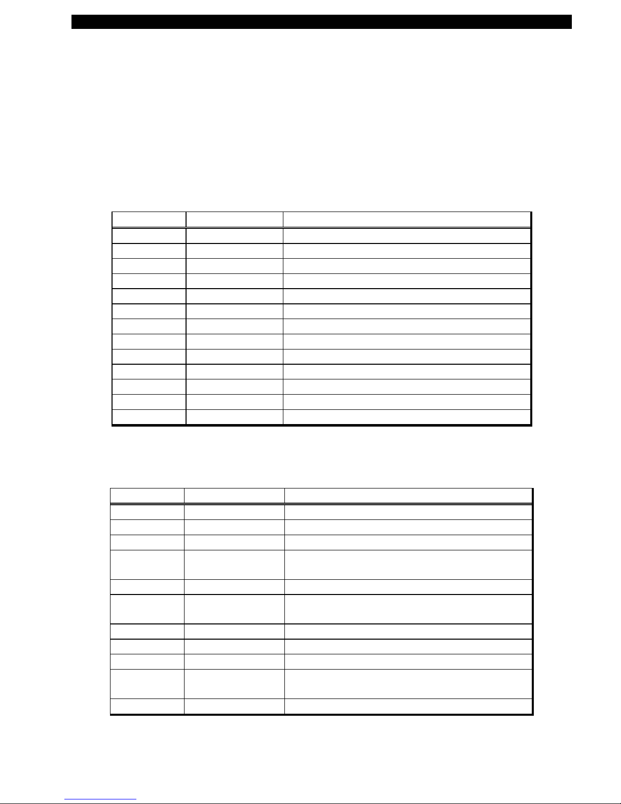
Replacement Parts
Replacement parts and pricing are available by contacting your Zebra distributor. Table 7 lists
replacement parts available for the T300 printer. Table 8 is a list of Maintenance Kits available for the
T
300 printer. These are only available in kit form, no piece parts in these kit are available separately.
Table 7. Replacement Parts
QUANTITY PART NUMBER DESCRIPTION
1 14500M Printhead (See Figure 15)
1 506009 Enclosure, Bottom (See Figure 16)
1 506010 Fascia, Front (See Figure 16)
4 506017 Bumper, Button (See Figure 16)
2 506020 Skewer, Ribbon (See Figure 11)
1 506024 Cover, Cutter (See Figure 23)
1 510000 Bar, Peel (See Figure 12)
1 548003 Label, Power/Feed (See Figure 3)
1 562000 Assy., Printhead Cable (See Figure 15)
1 562001 Harness, Sensors (See Figure 20)
1 569000 T ake Label Sensor (No t Illustrated)
1 580000M PCB Main (See Figure 21)
1 510012 Ribbon Guide Bracket (See Figure 15)
Table 8. Maintenance Kits
QUANTITY PART NUMBER DESCRIPTION
1 503009M Kit, Top Enclosure T300 printer (See Figure 16)
1 503010M Kit, Media Support T300 printer (See Figure 22)
1 503011M Kit, Platen Roller T300 printer (See Figure 12)
1 503012M Kit, Latch Printhead Assy. T300 printer (See
Figure 14)
1 503013M Kit, Stepper Mo tor T300 printer (See Figure 19)
1 503014M Kit, Control Panel PCB T300 printer (See Figure
18)
1 503015M Kit, Cutter Module T300 printer (See Figure 23)
1 503016M Kit, Media Guide T300 printer (See Figure 24)
1 503017M Kit, Ribbon Handler Assy. (See Figure 14)
1 503018M Kit, Sensor Assy. Ribbon Out T300 printer (See
Figure 25)
1 503019M Kit, Screw T300 printer (Not Illustrated)
Part # 547001L Rev. 2 Page 31
Page 39

Zebra T300 Printer Maintenance Manual
Figure 22. Media Support Kit PN 503010M
Figure 23. Cutter Module Kit PN 503015M
Page 32 Part # 547001L Rev. 2
Page 40

Zebra T300 Printer Maintenance Manual
Figure 24. Media Guide Kit PN 503016M
Figure 25. Ribbon Out Sensor Assembly Kit PN 503018M
Part # 547001L Rev. 2 Page 33
 Loading...