

Page 1

PL 360/460 Cradle
Page 2

PL 360/460 Cradle
© 2001 SYMBOL TECHNOLOGIES, INC. All rights reserved.
Symbol reserves the right to make changes to any product to improve reliabilit y,
function, or design.
Symbol does not assume any product liability arising out of, or in connection with, the
application or use of any product, circuit, or application described herein.
No license is granted, either expressly or by implication, estoppel, or otherwise under
any patent right or patent, covering or relating to any com bination, system, apparatus,
machine, material, method, or process in which Symbol products might be used. An
implied license only exists for equipment, circuits, and subsystems contained in Symbol
products.
Symbol and the Symbol logo are reg istered trademarks of Symbol Technologies, Inc.
Other product names mentioned in this manual may be trademarks or registered
trademarks of their respective companies and are hereby acknowledged.
Symbol Technologies, Inc.
One Symbol Plaza
Holtsville, N.Y. 11742-1300
http://www.symbol.com
Patents
This product is covered by one or more of the following U.S. and foreign Patents:
U.S. Patent No. 4,460,120; 4,496,831; 4,593,186; 4,603,262; 4,607,156; 4,652,750;
4,673,805; 4,736,095; 4,758,717; 4,816,660; 4,845,350; 4,896,026; 4,897,532; 4,923,281;
4,933,538; 4,992,717; 5,015,833; 5,017,765; 5,021,641; 5,029,183; 5,047,617; 5,103,461;
5,113,445; 5,130,520; 5,140,144; 5,142,550; 5,149,950; 5,157,687; 5,168,148; 5,168,149;
5,180,904; 5,216,232; 5,229,591; 5,230,088; 5,235,167; 5,243,655; 5,247,162; 5,250,791;
5,250,792; 5,260,553; 5,262,627; 5,262,628; 5,266,787; 5,278,398; 5,280,162; 5,280,163;
5,280,164; 5,280,498; 5,304,786; 5,304,788; 5,306,900; 5,321,246; 5,324,924; 5,337,361;
5,367,151; 5,373,148; 5,378,882; 5,396,053; 5,396,055; 5,399,846; 5,408,081; 5,410,139;
5,410,140; 5,412,198; 5,418,812; 5,420,411; 5,436,440; 5,444,231; 5,449,891; 5,449,893;
5,468,949; 5,471,042; 5,478,998; 5,479,000; 5,479,002; 5,479,441; 5,504,322; 5,519,577;
5,528,621; 5,532,469; 5,543,610; 5,545,889; 5,552,592; 5,557,093; 5,578,810; 5,581,070;
5,589,679; 5,589,680; 5,608,202; 5,612,531; 5,619,028; 5,627,359; 5,637,852; 5,664,229;
5,668,803; 5,675,139; 5,693,929; 5,698,835; 5,705,800; 5,714,746; 5,723,851; 5,734,152;
5,734,153; 5,742,043; 5,745,794; 5,754,587; 5,762,516; 5,763,863; 5,767,500; 5,789,728;
5,789,731; 5,808,287; 5,811,785; 5,811,787; 5,815,811; 5,821,519; 5,821,520; 5,823,812;
5,828,050; 5,850,078; 5,861,615; 5,874,720; 5,875,415; 5,900,617; 5,902,989; 5,907,146;
5,912,450; 5,914,478; 5,917,173; 5,920,059; 5,923,025; 5,929,420; 5,945,658; 5,945,659;
5,946,194; 5,959,285; 6,002,918; 6,021,947; 6,047,892; 6,050,491; 6,053,413; 6,056,200;
6,065,678; 6,067,297; 6,068,190; 6,082,621; 6,084,528; 6,088,482; 6,092,725; 6,101,483;
6,102,293; 6,104,620; 6,114,712; 6,115,678; 6,119,944; 6,123,265; 6,131,814; 6,138,180;
6,142,379; D305,885; D341,584; D344,501; D359,483; D362,453; D363,700; D363,918;
D370,478; D383,124; D391,250; D405,077; D406,581; D414,171; D414,172, D418,500;
D419,548; D423,468; D424,035 D431,158; D430,159; D431,562.
Invention No. 55,358; 62,539; 69,060; 69,187 (Taiwan); No. 1,601,796; 1,907,875;
1,955,269 (Japan).
European Patent 367,299; 414,281; 367,300; 367,298; UK 2,072,832; France 81/03938;
Italy 1,138,713.
rev. 09/00
Page 3

Quick Reference
The PhaserLink PL 360/460 Cradle acts as a stand, host
communication interface, and a charger for the Phaser Scanner. It
can sit on a desktop or be wall-mounted - whichever is more
convenient.
The cradle receives data from the scanner via connectors in the
bottom of the scanner and the top of the cradle. It then transmits
that data to the host device through an attached cable.
The cradle also provides power for charging the scanner’s battery
pack (in the scanner). The cradle has a charge status indicator light.
There are two versions of the cradle available:
• PL 460 Cradle: the batch retail version
• PL 360 Cradle: the batch industrial version
This Quick Reference Guide provides basic instruction on the set up
and use of the cradle. Unless otherwise noted, the term PhaserLink
refers to all versions of the cradle.
Equipment Supplied
The equipment supplied is:
• Two Screws (for wall mounting)
• One Velcro Strip (for desk mounting)
• Four Rubber Feet (for desk mounting)
•This Guide
•Cradle
Save the shipping container for storing or shipping. Inspect all your
equipment for damage. If anything is damaged or missing, call your
authorized Customer Support Representative immediately.
Related Documentation
Phaser Series Scanner Product Reference Guide,
p/n 70-33629-xx
P 360/460 Memory Scanner Quick Reference Guide,
p/n 70-33628-xx
1
Page 4

PL 360/460 Cradle
Parts of the Cradle
This figure shows the parts of the PhaserLink Cradle:
Scanner
Support
Ta b
Charging/
Communications
Contacts
Charging
LED
Indicator
COM 1
COM 2
Wal lmounting
Socket 1
Power
Port
Wall mounting
Socket 2
2
Page 5

Quick Reference
Connecting To The Host
On the bottom of the cradle are three ports -
COM 1
COM 2
COM 1 connects to the host computer, COM 2 is used for daisychaining multiple cradles together, and the Power Port supplies
power to the cradle.
1. Insert the independent power plug into the Power Port (the
cradle cannot be powered by the host computer).
Power Po rt
3
Page 6
PL 360/460 Cradle
2. Insert the cable from the host computer into COM 1 and the
cable to the other cradles, if any, into COM 2.
Daisy-Chaining
Note: The cradle suppor ts daisy-c haining w hen conne cted to a seri al host
and not when using Synapse interfaces.
To daisy-chain two or more cradles together, connect COM 1 of the
first cradle to the host and COM 2 to COM 1 of the second cradle.
Then connect COM 2 of the second cradle to COM 1 of the third
cradle. You can daisy-chain up to 12 cradles to one host in this
manner.
Wall Mounting
Before wall-mounting the cradle, the scanner support tab must be
changed from the desk-mount position to the wall-mount position.
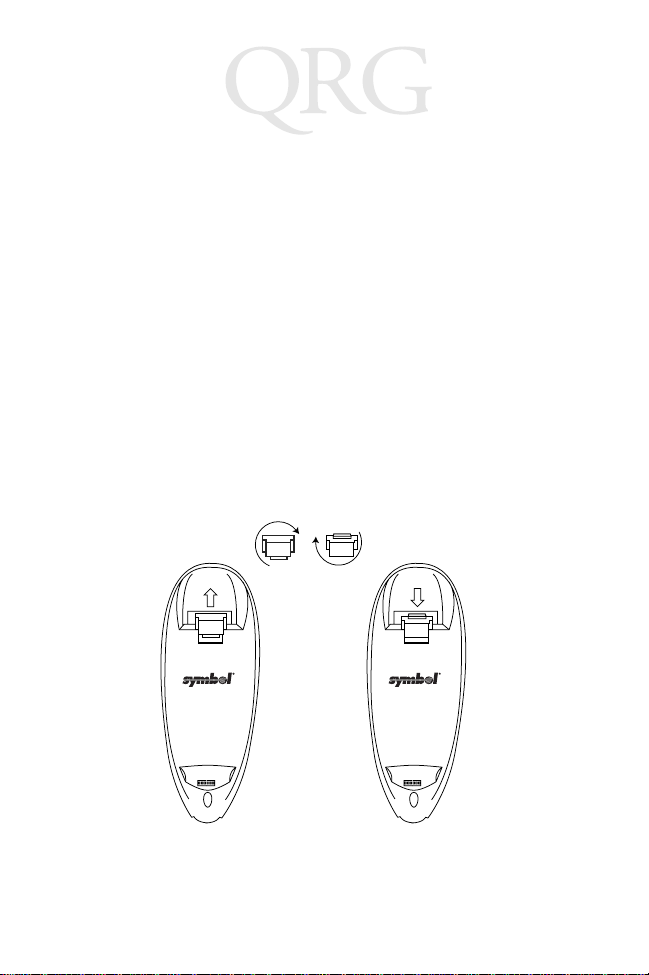
1. Lift the scanner support tab out of the top part of the cradle
and replace it in the wall-mount position, as shown:
Desk Mount
Wall Mount
4
Page 7
Quick Reference
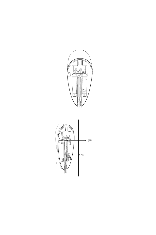
2. Seat the cables from the bottom of the cradle in the grooves
along the length of it so that the bottom of the cradle is
smooth and flat, as shown:
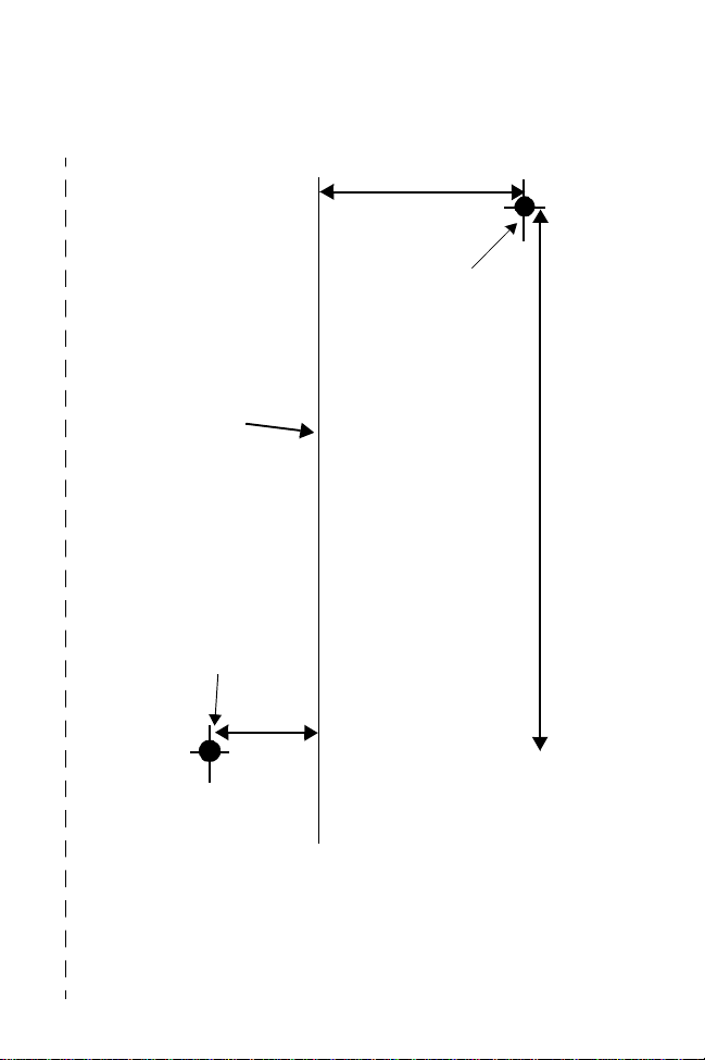
3. Secure two screws (included) to the wall. A template is
provided for you on page 11.
4. Fasten the screws into the wall where the cradle will hang,
leaving about 1/8” (.3 cm) of the screw outside the wall so that
the cradle will have something to hang on.
5. Place the cradle over the screw heads and slide down until it
fits into place. Slight pressure upwards should not move the
cradle.
6. Place the Phaser in the cradle.
5
Page 8
PL 360/460 Cradle
Inserting Phaser in the Cradle
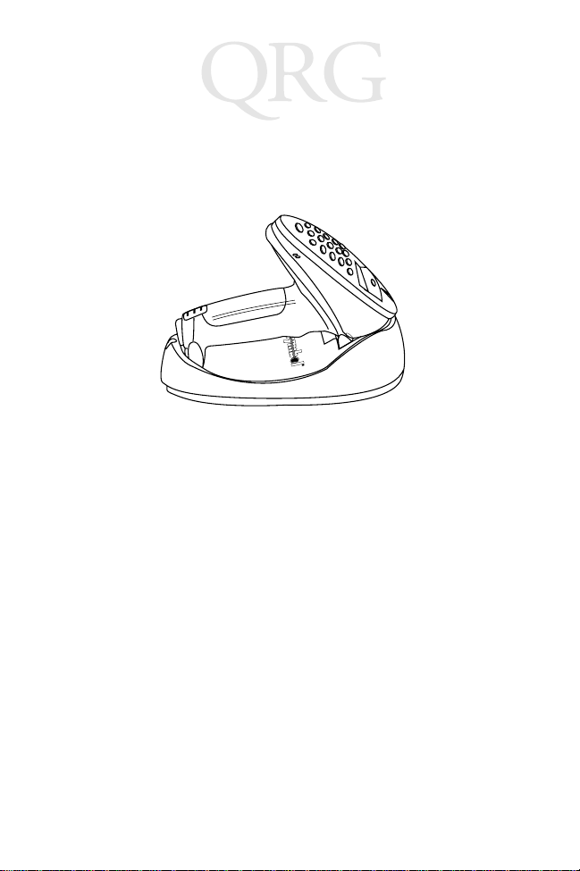
Place the Phaser scanner in the cradle so that the top of the scanner
sits in the larger part of the cradle and the metal contacts on the
bottom of the scanner touch the contacts on the cradle, like so:
Sending Data to Host Computer
To set up the PhaserLink Cradle for communications between a
Phaser and a host computer:
1. Connect the cradle to the host computer as described in
Connecting To The Host on page 3.
2. Insert the Phaser in the cradle.
3. Start the communications program on the host computer and
the Phaser.
Recharging the Battery in the Phaser
1. Connect the cradle to a receptacle supplying AC power of the
proper voltage level.
2. Place the scanner in the cradle, ensuring the metal contacts on
the bottom of the scanner touch the contacts on the cradle.
3. A complete charge takes up to 4 hours, depending upon the remaining charge in the battery of the scanner.
6
Page 9
Quick Reference
Indicator LED
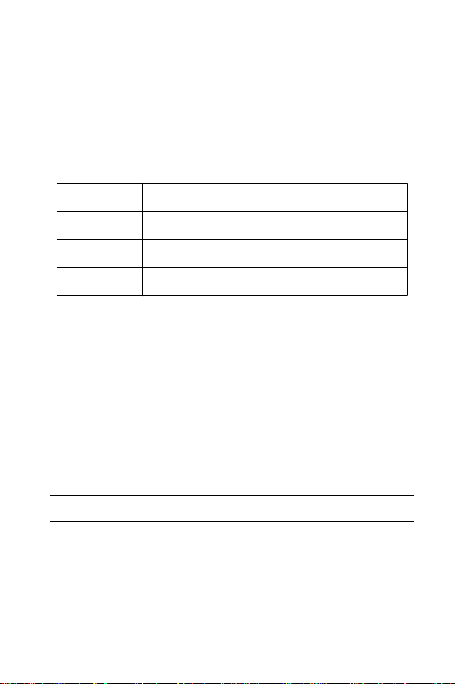
Once the scanner is placed in the cradle, it will wait 15 minutes to
start charging the battery in the scanner. The LED blinks in a
specific pattern to show what the cradle is doing:
Off The scanner is not in the cradle
Slow Blink
Fast Blink Scanner is in cradle, charging
On
Scanner is in cradle, not charging
Scanner is in cradle, charge cycle is complete
Troubleshooting
If the cradle does not work after you’ve followed these operating
instructions:
• Check the system power.
• Check for loose cable connections.
• Check the scanner is sitting properly in the cradle.
Cleaning
Wipe the cradle periodically with a lens tissue or other material
suitable for cleaning optical material, such as eyeglasses.
Caution: Do not pour, spray or spill any liquid on the cradle.
7
Page 10

PL 360/460 Cradle
Regulatory Information
Radio Frequency Interference Requirements
This device has been tested and found to comply with the limits for a Class B digital
device pursuant to Part 15 of the Federal Communicati ons Commissions Rules and
Regulation. These limits are designed to provide reasonable protection against harmful
interference when the equipment is operated in a commercial environment. This
equipment generates, uses, and can radiate radio frequency energy and, if not installed
and used in accordance with the instruction manual, may cause harmful interference to
radio communications. Operation of this equipment in a residential area is likely to
cause harmful interference in which case the user will be required to correct the
interference at his own expense.
However, there is no guarantee that interference will not occur in a particular
installation. If the equipment does cause harmful interference to radio or television
reception, which can be determined by turning the equipment off and on, the user is
encouraged to try to correct the interference by one or more of the following measures:
• Re-orient or relocate the receiving antenna.
• Increase the separation between the equipment and receiver.
• Connect the equipment into an outlet on a circuit different from that which the
receiver is connected.
• Consult the dealer or an experienced radio/TV technician for help.
Radio Frequency Interference Requirements - Canada
This Class B digital appara tus meets the requirements of the Canadi an InterferenceCausing Equipment Regulations.
Cet appareil numérique de la Classe A respecte toutes les exigences du Reglement sur
le Materiél Brouilleur du Canada.
CE Marking and European Union Compliance
Products intended for sale within the European Union are marked with the
CE Mark which indicates compliance to applicable Directives and
European Normes (EN), as follows. Amendments to these Directives or
ENs are included:
Applicable Directives
• Electromagnetic Compatibility Directive 89/336/EEC
• Low Voltage Directive 73/23/EEC
Applicable Standards
• EN 55022:1998, Limits and Methods of Measurement of Radio Disturbance
Characteristics of Information Technology Equipment
• EN 55024:1998; Information Technology equipment - Immunity characteristics -
Limits and methods of measurement
8
Page 11

Quick Reference
• IEC 1000-4-2:1995; Electromagnetic compatibility (EMC); Part 4:Testing and
measurement techniques; Section 4.2:Electrostatic discharge immunity test
• IEC 1000-4-3:1997; Electromagnetic Compatibility (EMC); Part 4:Testing and
measurement techniques; Section 3. Radiated, radio frequency, electromagnetic
field immunity test.
• IEC 1000-4-4:1995; Electromagnetic compatibility (EMC); Part 4: Testing and
measurement techniques; Section 4:Testing electrical fast transient,/Burst immunity.
• IEC1000-4-5:1995; Electromagnetic compatibility (EMC), Part 4: Testing and
measurement techniques; Section 5: Surge Immunity
• IEC 1000-4-6:1996; Electromagnetic compatibility (EMC), Part 4:Testing and
measurement techniques; Section 6: Immunity to conducted disturbances,
induced by radio frequency fields.
• IEC 1000-4-11:1994; Electromagnetic compatibility (EMC), Part 4: Testing and
measurement techniques; Section 11: Voltage Dips, Short Interruptions, and Voltage Variations.
• EN 60 950 + A1+A2+A3+A4+A11 - Safety of Information Technology Equipment Including Electrical Business Equipment
9
Page 12
PL 360/460 Cradle
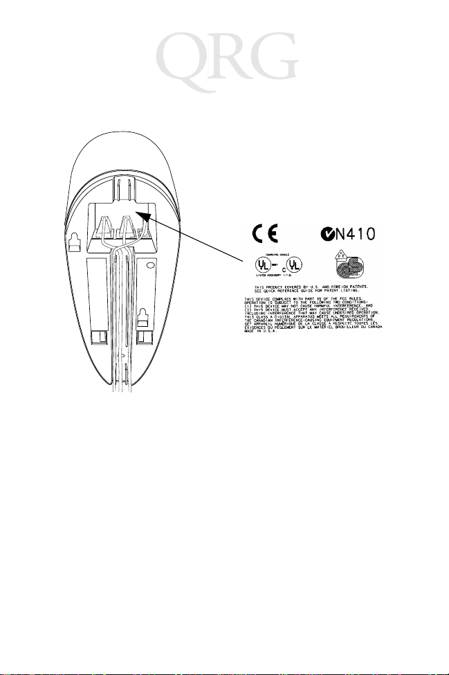
EN 60 825-1 (EN 60 825) - Safety of Devices Containing Lasers Cradle Labeling
RF Devices
Symbol’s RF products are designed to b e compliant with t he rules and regulations in
the locations into which they are sold and will be labeled as required. The majority of
Symbol’s RF devices are type approved and do not require the user to obtain license or
authorization before using the equipment. Any changes or modifications to Symbol
Technologies equipment not expressly approved by Symbol Technologies could void
the user’s authority to operate the equipment.
10
Page 13
Quick Reference
Wall Mounting Template:
Center
Line of
Cradle
Wall
Mounting
Socket 2
1 5/16”
Wall
Mounting
Socket 1
Use 1/8” drill
bit for the
screw holes.
3 1/2”
11/16”
11
Page 14

PL 360/460 Cradle
this page intentionally left blank
12
Page 15

Quick Reference
Warranty
Symbol Technologies, Inc. (“Symbol”) manufactures its hardware products in accordance with
industry-s tandard pra ctices. Symbol warrants that f or a peri od of twelve (12) months from date of
shipment, products will be free from defects in materials and workmanship.
This warranty is provided to the original owner only and is not transferable to any third party. It shall
not apply to any product (i) which has been repaired or altered unless done or approved by Symbol,
(ii) which has not been maintained in accordance with any operating or handling instructions supplied
by Symbol, (iii) which has been subjected to unusual physical or electrical stress, misuse, abuse, power
shortage, negligence or accident or (iv) which has been used other than in accordance with the product
operating and handling instructions. Preventive maintenance is the responsibility of customer and is
not covered under this warranty.
Wear items and accessories having a S ymbol serial number will carry a 90-day limited warranty. Nonserialized items will carry a 30-day limited warranty.
Warranty Coverage and Procedure
During the warranty period, Symbol will repair or replace defective products returned to Symbol’s
manufacturing plant in the US. For warranty service in North America, call the Symbol Support
Center at 1-800-653-5350. International customers should contact the local Symbol office or support
center. If warranty service is required, Symbol will issue a Return Material Authorization Number.
Products must be shipped in the original or comparable packaging, shipping and insurance charges
prepaid. Symbol will ship the repaired or replacement product freight and insuranc e prepaid in North
America. Shipments from the US or other locations will be made F.O.B. Symbol’s manufacturing
plant.
Symbol will use new or refurbished parts at its discretion and will own all parts removed from
repaired products. Customer will pay for the replacement product in case it does not return the
replaced product to Symbol within 3 days of receipt of the replacement product. The process for
return and cust omer’s charges will be in accordance with Symbol’s Exchange Policy in effect at the
time of the exchange.
Customer accepts full responsibility for its software and data including the appropriate backup
thereof.
Repair or replacement of a product during warranty will not extend the original warranty term.
Symbol’s Customer Service organization offers an array of service plans, such as on-site, depot, or
phone support, that can be implemented to meet customer’s special operational requirements and are
available at a substantial discount during warranty period.
General
Except for the warranties stated above, Symbol disclaims all warranties, express or implied, on
products furnished hereunder, including without limitation implied warranties of merchantability and
fitness for a particular purpose. The stated express warranties are in lieu of all obligations or liabilities
on part of Symbol for damages, including without limitation, special, indirect, or consequential
damages arising out of or in connection with the use or performance of the product.
Seller’s liability for damages to buyer or others resulting from the use of any product, shall in no way
exceed the purchase price of said product, except in instances of injury to persons or property.
Some stat es (or jurisdictions) do not allow the exclusi on or limitation of incidental o r cons equential
damages, so the preceding exclusion or limitation may not apply to you.
13
Page 16

Service Information
Before you use the unit, it must be configured to operate in your facility ’s network and
run your applications.
If you have a problem running your unit or using your equipment, contact your
facility’s Technical or Systems Support. If there is a problem with the equipment, they
will contact the Symbol Support Center:
United States 1-800-653-5350 Canada 905-629-7226
United Kingdom 0800 328 2424 Asia/Pacific 337-6588
Australia 1-800-672-906 Austria 1-505-5794
Denmark 7020-1718 Finland 9 5 407 580
France 01-40-96-52-21 Germany 6074-49020
Italy 2-484441 Mexico 5-520-1835
Netherlands 315-271700 Norway 66810600
South Africa 11-4405668 Spain 9-1-320-39-09
Sweden 84452900
Latin America Sales Support 1-800-347-0178 Inside US
Europe/Mid-East Distributor Operations Contact local distribu tor or call
+1-561-483-1275 Outside US
+44 208 945 7360
70-33657-01
Revision C — April 2001
Symbol Technologies, Inc. One Symbol Plaza Holtsville, NY 11742-1300
 Loading...