

Page 1
NX-9600/NX-9610 Series
Integrated Services Controller
Installation Guide
Page 2

2 NX-9600/NX-9610 Series Integrated Services Controller
Zebra and the Zebra head graphic are registered trademarks of ZIH Corp. The Symbol logo is a registered
trademark of Symbol Technologies, Inc., a Zebra Technologies company.
© 2015 Symbol Technologies, Inc
.
Page 3

Installation Guide 3
1.0 Introduction . . . . . . . . . . . . . . . . . . . . . . . . . . . . . . . . . . . . . . . . . . . . . . . . . . . . . . . . . . . . . . . . . . . . 4
1.1 Document Conventions . . . . . . . . . . . . . . . . . . . . . . . . . . . . . . . . . . . . . . . . . . . . . . . . . . . . . . . . . . 4
1.2 Warnings . . . . . . . . . . . . . . . . . . . . . . . . . . . . . . . . . . . . . . . . . . . . . . . . . . . . . . . . . . . . . . . . . . . . . 5
1.3 Site Preparation . . . . . . . . . . . . . . . . . . . . . . . . . . . . . . . . . . . . . . . . . . . . . . . . . . . . . . . . . . . . . . . . 5
1.3.1 Installation Checklist . . . . . . . . . . . . . . . . . . . . . . . . . . . . . . . . . . . . . . . . . . . . . . . . . . . . . . . . 6
1.4 Cautionary Statements . . . . . . . . . . . . . . . . . . . . . . . . . . . . . . . . . . . . . . . . . . . . . . . . . . . . . . . . . . . 7
1.5 Safety Instructions for Rack Mount Installations. . . . . . . . . . . . . . . . . . . . . . . . . . . . . . . . . . . . . . .8
2.0 NX-9600 Series Specifications . . . . . . . . . . . . . . . . . . . . . . . . . . . . . . . . . . . . . . . . . . . . . . . . . . . . 9
2.1 Mechanical Specifications . . . . . . . . . . . . . . . . . . . . . . . . . . . . . . . . . . . . . . . . . . . . . . . . . . . . . . . .9
2.2 Environmental Specifications. . . . . . . . . . . . . . . . . . . . . . . . . . . . . . . . . . . . . . . . . . . . . . . . . . . . . . 9
2.3 Power Specifications . . . . . . . . . . . . . . . . . . . . . . . . . . . . . . . . . . . . . . . . . . . . . . . . . . . . . . . . . . . . 9
2.4 Power Protection . . . . . . . . . . . . . . . . . . . . . . . . . . . . . . . . . . . . . . . . . . . . . . . . . . . . . . . . . . . . . . 10
3.0 Hardware Installation . . . . . . . . . . . . . . . . . . . . . . . . . . . . . . . . . . . . . . . . . . . . . . . . . . . . . . . . . . . 11
3.1 Installing the NX-9600 Controller. . . . . . . . . . . . . . . . . . . . . . . . . . . . . . . . . . . . . . . . . . . . . . . . . . 11
3.2 Applying Power to the Controller . . . . . . . . . . . . . . . . . . . . . . . . . . . . . . . . . . . . . . . . . . . . . . . . . . 12
4.0 Physical Interface LEDs . . . . . . . . . . . . . . . . . . . . . . . . . . . . . . . . . . . . . . . . . . . . . . . . . . . . . . . . . 13
4.1 Front Panel LEDs . . . . . . . . . . . . . . . . . . . . . . . . . . . . . . . . . . . . . . . . . . . . . . . . . . . . . . . . . . . . . . . 13
4.2 Power Supply Status LED . . . . . . . . . . . . . . . . . . . . . . . . . . . . . . . . . . . . . . . . . . . . . . . . . . . . . . . . 13
4.3 Gigabit Ethernet Card LEDs . . . . . . . . . . . . . . . . . . . . . . . . . . . . . . . . . . . . . . . . . . . . . . . . . . . . . . 14
4.4 NX-9610 Expansion Module LEDs . . . . . . . . . . . . . . . . . . . . . . . . . . . . . . . . . . . . . . . . . . . . . . . . . 14
5.0 Using the NX-9600 Series Command Line Interface . . . . . . . . . . . . . . . . . . . . . . . . . . . . . . . . . 15
6.0 Basic Configuration Using the Management Interface . . . . . . . . . . . . . . . . . . . . . . . . . . . . . . 16
7.0 Regulatory Information . . . . . . . . . . . . . . . . . . . . . . . . . . . . . . . . . . . . . . . . . . . . . . . . . . . . . . . . . . 18
7.1 Waste Electrical and Electronic Equipment (WEEE) . . . . . . . . . . . . . . . . . . . . . . . . . . . . . . . . . . . 22
7.2 Turkish WEEE Statement of Compliance . . . . . . . . . . . . . . . . . . . . . . . . . . . . . . . . . . . . . . . . . . . .23
8.0 Support . . . . . . . . . . . . . . . . . . . . . . . . . . . . . . . . . . . . . . . . . . . . . . . . . . . . . . . . . . . . . . . . . . . . . . . 24
9.0 Symbol Technologies End-User Software License Agreement . . . . . . . . . . . . . . . . . . . . . . . 25
10.0 NX-96 Series China ROHS Compliance . . . . . . . . . . . . . . . . . . . . . . . . . . . . . . . . . . . . . . . . . . . 32
Page 4
4 NX-9600/NX-9610 Series Integrated Services Controller
!
1 Introduction
The NX-9600 Series Integrated Services Controller lets you centrally administer networks up to 10,000 WLAN
Access Points geographically dispersed over numerous telecommuter and small or medium sized enterprise
locations.
WiNG Access Points intelligently manage traffic, Quality of Service (QoS), mobility, and security at remote
locations, while the NX-9600 and NX-9610 provide a single point for configuration, provisioning,
monitoring/analytics, and remote troubleshooting. Hotspot configuration, security policy management, and
statistics aggregation are alsol administered through the NX-9600 series integrated services controller. The
efficient WLAN architecture supports easy network configuration, and reduces the hardware expense required to
support large networks.
1.1 Document Conventions
The following graphical alerts are used in this document to indicate notable situations:
NOTE Tips, hints, or special requirements that you should take note of.
CAUTION Care is required. Disregarding a caution can result in data loss or equipment
malfunction.
WARNING! Indicates a condition or procedure that could result in personal injury or equipment
damage.
Page 5

Installation Guide 5
1.2 Warnings
• Read all installation instructions and site survey reports, and verify correct equipment installation before
connecting the appliance to its power source.
• Remove jewelry and watches before installing this equipment.
• Verify the unit is grounded before connecting it to the power source.
• Verify any device connected to this unit is properly wired and grounded.
• Connect all power cords to a properly wired and grounded electrical circuit.
• Verify the electrical circuits have appropriate overload protection.
• With a fiber optic module installed, this device emits Class I (or 1) output with fiber cable disconnected.
• Attach only approved power cords to the device.
• Verify the power connector and socket are accessible at all times during operation of the equipment.
• Do not work with power circuits in dimly lit spaces.
• Do not install equipment or work with its power circuits during thunderstorms, or other weather conditions
that could cause a power surge.
• Verify adequate ventilation around the device.
• Ensure ambient temperatures meet equipment operation specifications.
1.3 Site Preparation
• Consult your site survey and network analysis reports to determine specific equipment placement, power
drops, and so on.
• Assign installation responsibility to appropriate personnel.
• Identify and document where all installed components are located.
• Provide a sufficient number of power drops for your equipment.
• Ensure adequate, dust-free ventilation to all installed equipment.
• Identify and prepare Ethernet and console port connections.
• Verify cable lengths are within the maximum allowable distances for optimal signal transmission.
Page 6

6 NX-9600/NX-9610 Series Integrated Services Controller
1.3.1 Installation Checklist
Location & Equipment
NX-9600 or NX 9610 shipping container contents:
• NX-9600/NX-9610 Series Integrated Services Controller
• Locking front bezel with keys
• Hard Disc Drive (HDD) tray keys
• Four-post mounting rail kit
• NX-9600/NX-9610 Series Integrated Services Controller Installation Guide
NOTE Keep the front bezel keys and HDD keys in a secure location which can only be
accessed by authorized personnel.
Additional Recommended Equipment
• Standard, grounded 100-240 VAC 50/60 Hz connection
• Uniterruptable Power Supply (UPS)
• Standard 19-inch rack (2U height) with mounting rails
(this document)
Page 7
Installation Guide 7
!
!
!
!
!
!
1.4 Cautionary Statements
CAUTION There are no user-serviceable components inside the NX-9600 series controller.
Opening the chassis will void the warranty.
CAUTION BIOS settings on the NX-9600 series controller should not be changed. Changing
any settings in the BIOS will void the warranty.
CAUTION To prevent the controller from overheating, never install in an enclosed area not
properly ventilated or cooled. For proper airflow, keep the front and back sides of
the controller clear of obstructions and away from the exhaust of other equipment.
CAUTION The recommended/ambient operating temperature is 0°C to 40°C. Installation in a
closed or multi-rack assembly may raise the immediate ambient temperature above
the average room temperature. Exercise due caution.
CAUTION Ensure the electrical circuit through which the services controller is powered can
safely accommodate an 800 Watt power supply.
CAUTION It is highly recommended to connect a NX-9600 series controller to an
Uninterruptible Power Supply (UPS). There are instances in which the system
software could become corrupt and un-recoverable, such as a power loss, a system
upgrade, database backup, or database restore operation.
Page 8
8 NX-9600/NX-9610 Series Integrated Services Controller
1.5 Safety Instructions for Rack Mount Installations
WARNING! An NX-9600 series controller requires a two man lift. Use all appropriate cautions.
• Rack Mount Brackets - Do not lift the NX-9600 series controller using the rack mount brackets.
• Rack Mount Rails - Use only industry-standard mounting kits when installing the NX-9600 series controller, as
improper mounting may result in hardware failure and hazardous conditions. Use the mounting rails included
with the controller.
• Elevated Operating Ambient Temperature - If installing a NX-9600 series controller in a closed or multi-unit
rack assembly, the operating ambient temperature of the rack environment may be greater than the room
ambient temperature. Consideration should be given to installing the appliance in an environment compatible
with the maximum ambient temperature (Tma) specified by the manufacturer.
• Reduced Air Flow - Installation of a NX-9600 series controller in a rack should be such that the amount of air
flow required for safe operation of the equipment is not compromised.
• Mechanical Loading - Mounting a NX-9600 series controller in a rack should be such that uneven mechanical
loading results in a hazardous condition.
• Circuit Overloading - Consideration should be given when connecting a NX-9600 series controller to the
supply circuit so that protection is provided to a NX-9600 series controller and supply wiring if any circuit
overloads occur. Appropriate consideration of equipment nameplate ratings should be used when addressing
this concern.
• Reliable Earthing - Reliable earthing (grounding) of a rack mounted NX-9600 series controller should be
maintained.
• Particular attention should be given to power connections other than direct connections to the branch circuit
(e.g., use of power strips).
Page 9
Installation Guide 9
2 NX-9600 Series Specifications
2.1 Mechanical Specifications
Size
Weight 50.2 lbs
Width: 19 inches
Depth: 28 inches
Height: 4 inches
2.2 Environmental Specifications
Operational Temperature Range 0°C to 40°C
Storage Temperature Range -40°C to 70°C
Operational Humidity Range 10% to 85% RH (non-condensing) @ 40°C
Storage Humidity Range 10% to 95% RH (non-condensing) @ 40°C
Operational Altitude Maximum 10,000 feet @ 25°C
2.3 Power Specifications
Input Voltage
Output Voltage
100 to 240VAC (+/- 10%), 50/60Hz, 10-5 Amps
+3.3 V @ 32 A, +5V @ 32 A, 5 Vsb @ 3.5 A, +12 V @ 65 A,
-12 V @ 0.8 A
Page 10
10 NX-9600/NX-9610 Series Integrated Services Controller
!
CAUTION A power cord is not supplied with a NX-9600 series controller. Use only a properly
rated power cord certified (as appropriate) for the country of operation.
2.4 Power Protection
• If possible, use a circuit dedicated to data processing equipment. Commercial electrical contractors familiar
with wiring for data processing equipment can help with the load balancing of these circuits.
• Install adequate surge protection. Be sure to use a surge protection device between the power source and a
NX-9600 series controller.
•Install an Uninterruptable Power Supply (UPS). A UPS of the proper capacity for the data processing equipment
must be purchased. A UPS provides continuous power during a power outage. Some UPS devices have
integrated surge protection. UPS equipment requires periodic maintenance to ensure reliability.
Page 11

Installation Guide 11
3 Hardware Installation
The following sections describe the hardware installation for a NX-9600 series controller:
3.1 Installing the NX-9600 Series Controller
1. Complete the instructions supplied with the rail kit to mount the NX-9600 in an equipment rack.
2. Connect the power cords for both power supplies.
3. Connect the Ethernet cables, and connect the controller to the network. Connect all other cables as
appropriate for your required configuration.
4. Using a console cable, connect the serial port to an RS-232 (DB-9) serial port on a separate computer (the
“configuration computer”).
NOTE If a power supply failure occurs, an audible alarm will sound. To silence the power
supply alarm, press and hold the red reset button next to the power supplies.
NOTE The 10GigE ports (xge1-xge4) are only available for NX-9610.
The NX-9600 series controller serial port functions as a console port, and can be used to access the Command
Line Interface (CLI) for system configuration. For more information, see
Line Interface on page 15
.
Using the NX-9600 Series Command
Page 12

12 NX-9600/NX-9610 Series Integrated Services Controller
3.2 Applying Power to the Controller
1. Gently press and hold the power button to apply power to the services ontroller.
2. Attach the front bezel between the rack mount brackets on the sides of the services controller.
3. Lock the front bezel.
NOTE Keep the front bezel keys and HDD keys in a secure location which can only be
accessed by authorized personnel.
Page 13

Installation Guide 13
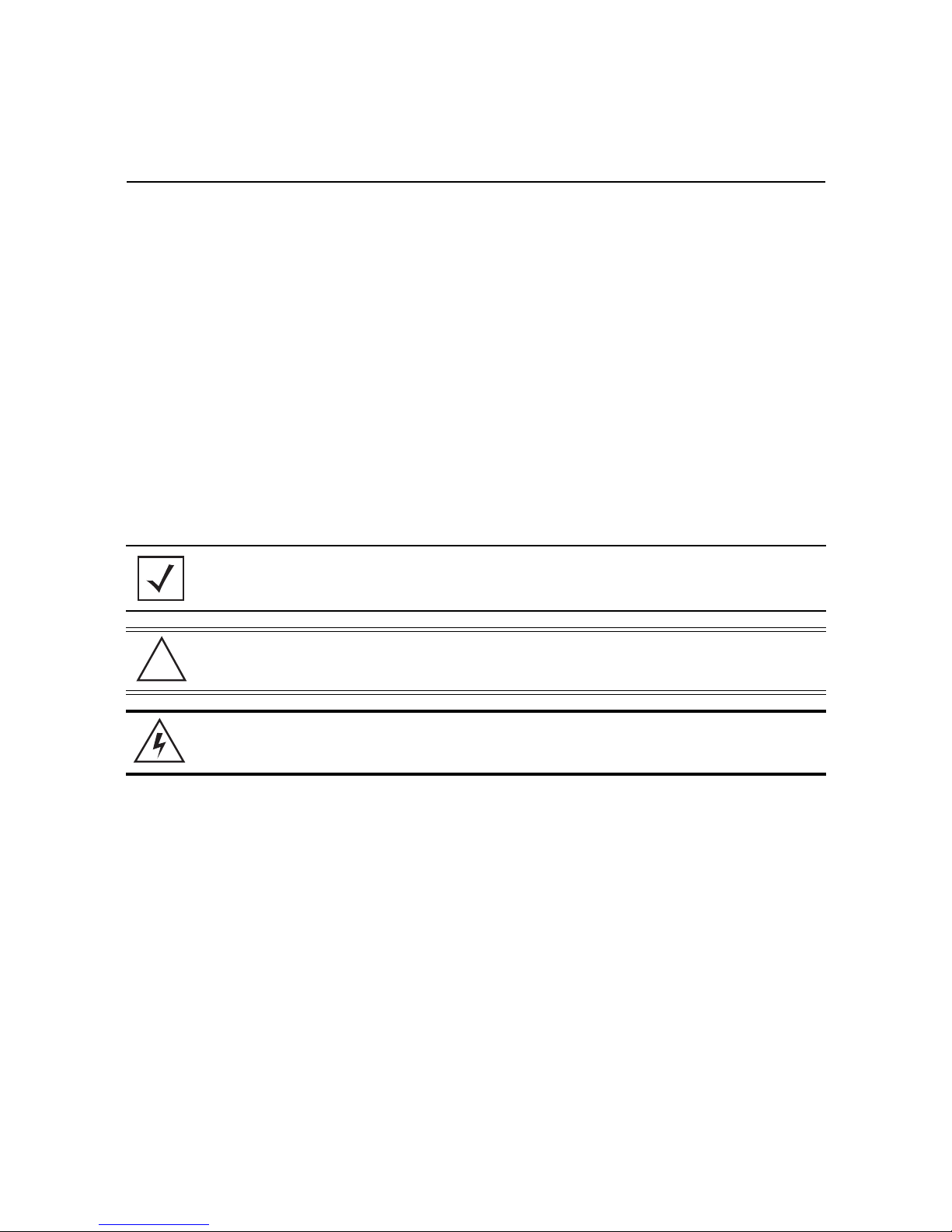
4 Physical Interface LEDs
4.1 Front Panel LEDs
LEDs for the front of the controller are as follows:
LED Color State
Gigabit Ethernet 2
Gigabit Ethernet 1
SDD Green Normal
Power
HDD 1-4 Blue
Blinking Amber
Blinking Amber
Green Active
Blinking Blue
Off/Red
Blinking Blue/Red
Active
Active
Normal
Active
Degrade
Rebuild
4.2 Power Supply Status LED
Each power supply module has a single bi-color LED to indicate power supply status. The LED is visible on the rear
of each installed power supply.
The LED functionality for the power supply is as follows:
LED Port/Connector Color State
Redundant power supplies Grounded AC
Green
Off
Power available
No power available (failed)
NOTE In the event of a PSU failure, an audible alarm will sound indicating replacement of the
PSU is required.
Page 14

14 NX-9600/NX-9610 Series Integrated Services Controller
4.3 Gigabit Ethernet Card LEDs
The LED functionality for the Gigabit Ethernet card is as follows:
LED Connector Color State
Gigabit Ethernet cards
10Mbps
100Mbps:
Green
Blinking Green
Link
Active
1000Mbps:
4.4 NX-9610 Expansion Module LEDs
The NX-9610 controller supports two 10GigE Peripheral Component Interconnect Express (PCIe) cards, and a
hardware cryptography engine for superior encryption/decryption performance.
The LED functionality for the PCIe cards and hardware cryptography engine is as follows:
LED Port/Connector Color State
10 Gigabit Ethernet cards
(NX-9610 only)
Cryptographic accelerator card
(NX-9610 only)
Top LED (Link Speed)
Bottom LED (Activity)
-
Green
Solid Green
Blinking Green
Green On/Red Off
Green Off/Red On
Link Active
Link Present
Link Active
Normal Function
Power Fault
Page 15

Installation Guide 15
5 Using the NX-9600 Series Command Line Interface
Once the NX-9600 series hardware is installed, complete the following to access the Command Line Interface
(CLI) on the controller:
1. On the configuration computer, configure a terminal emulation application as follows:
Term i nal Typ e
Port
Terminal Settings
VT 100
COM port
19200bps transfer rate
8 data bits
no parity
1 stop bit
no flow control
no hardware compression
2. Apply power to the device.
3. When the prompt is displayed in the terminal window, login using the username admin and
password admin123.
4. For increased security, you are prompted to enter a new password. Enter the new password then
enter it again to confirm it.
Page 16

16 NX-9600/NX-9610 Series Integrated Services Controller
6 Basic Configuration Using the Management Interface
Once the NX 9600 series controller hardware is installed and powered on, complete the following to access the
Management Interface functions:
1. Connect one end of an Ethernet cable to one of the ports on the back of the NX-9600 series controller, and
connect the other end to a computer with a working Web browser.
2. Set the computer to use an IP address between 192.168.0.10 and 192.168.0.254 on the connected port. Set a
subnet /network mask of 255.255.255.0.
3. Once the computer has an IP address, point the Web browser to: https://192.168.0.1
screen displays:
. The following login
4. Enter the default username admin in the Username field.
5. Enter the default password admin123 in the Password field.
6. Click Login. You are prompted to change your password.
Page 17

Installation Guide 17
7. Enter a new password, then enter it again to confirm it.
8. Click Apply. The password change is confirmed.
9. Click OK. The NX-9600 Dashboard displays.
You have now established a connection to the NX-9600 Management Interface.
For software configuration, please see the current WiNG Contrroller and Service Paltform Reference
Guide available from the Support Website at www.zebra.com/support
.
Page 18

18 NX-9600/NX-9610 Series Integrated Services Controller
7 Regulatory Information
This guide applies to the following Model Number: NX-96
All Zebra devices are designed to be compliant with rules and regulations in locations they are sold and will be
labeled as required.
Local language translations are available at the following Website: www.zebra.com/support
Any changes or modifications to Zebra equipment, not expressly approved by Zebra, could void the user's
authority to operate the equipment.
Declared maximum operating temperature: 40°C.
Radio Frequency Interference Requirements - FCC
This equipment has been tested and found to comply with the limits for a Class A digital device, pursuant to Part
15 of the FCC rules. These limits are designed to provide reasonable protection against harmful interference when
the equipment is operated in commercial environment. This equipment generates, uses, and can radiate radio
frequency energy and, if not installed and used in accordance with the instruction manual, may cause harmful
interference to radio communications. Operation of this equipment in a residential area is likely to cause harmful
interference in which case the user will be required to correct the interference at his own expense.
Radio Frequency Interference Requirements - Canada
This Class A digital apparatus complies with Canadian ICES-003.
Cet appareil numérique de la classe A est conforme à la norme NMB-003 du Canada.
CAN ICES-3 (A)/NMB-3(A)
.
Page 19

Installation Guide 19
!
Battery Information
Risk of explosion if battery is replaced by an incorrect type.
Dispose of batteries according to instructions.
Use only approved batteries.
Zebra uses batteries designed and constructed to the highest standards within the industry.
However, there are limitations to how long a battery can operate or be stored before needing replacement. Many
factors affect the actual life cycle of a battery pack, such as heat, cold, harsh environmental conditions and severe
drops.
When batteries are stored over six (6) months, some irreversible deterioration in overall battery quality may occur.
Store batteries at half of full charge in a dry, cool place, removed from the equipment to prevent loss of capacity,
rusting of metallic parts and electrolyte leakage. When storing batteries for one year or longer, the charge level
should be verified at least once a year and charged to half of full charge.
Replace the battery when a significant loss of run time is detected.
Standard warranty period for batteries is 30 days, regardless if the battery was purchased separately or included
with the device.
Battery Safety Guidelines
• Follow battery usage, storage, and charging guidelines found in this guide.
• Improper battery use may result in a fire, explosion, or other hazard.
• To charge the device battery, the battery and charger temperatures must be between +32 ºF and +104 ºF (0 ºC
and +40 ºC)
• Do not use incompatible batteries and chargers. Use of an incompatible battery or charger may present a risk of
fire, explosion, leakage, or other hazard. If you have any questions about the compatibility of a battery or a
charger, contact Support.
• For devices that utilize a USB port as a charging source, the device shall only be connected to products that
bear the USB-IF logo or have completed the USB-IF compliance program.
• Do not short circuit a battery or allow metallic or conductive objects to contact the battery terminals.
• Do not modify or remanufacture, attempt to insert foreign objects into the battery, immerse or expose to water
or other liquids, or expose to fire, explosion, or other hazard.
• Do not leave or store the equipment in or near areas that might get very hot. Do not place battery into a
microwave oven or dryer.
• Please follow local regulations to promptly dispose of used re-chargeable batteries.
• Do not dispose of batteries in fire.
Page 20

20 NX-9600/NX-9610 Series Integrated Services Controller
!
• Seek medical advice immediately if a battery has been swallowed.
Laser Devices
Class 1 laser devices are not considered hazardous when used for their intended purpose.
LED Devices
For LED devices which have been evaluated to IEC 62471 and comply with the Exempt Risk Group, no product
labeling requirements apply. However, the following statement is required to comply with US and international
regulations:
LED Compliance Statement:
Classified as "EXEMPT RISK GROUP" according to IEC 62471:2006 and EN 62471:2008
Fiber Optic Module
With fiber optic module installed, emits Class I (or 1) output with fiber cable disconnected.
Marking and European Economic Area (EEA)
WARNING: This is a Class A product. In a domestic environment this product may cause radio interference in
which case the user may be required to take adequate measures.
The use of RFID Devices has varying restrictions for use within the EEA; please refer to the Declaration of
Conformity (DoC) for details at www.zebra.com/doc
Statement of Compliance
Zebra hereby declares that this device is in compliance with all the applicable Directives, 2004/108/EC,
2006/95/EC and 2011/65/EU. A Declaration of Conformity (DoC may be obtained from
www.zebra.com/doc
.
.
Page 21

Installation Guide 21
Japan (VCCI) Voluntary Control Council for Interference
Class A ITE
Korea Warning Statement for Class A ITE
기 종 별 사 용 자 안 내 문
A급 기기
( 업무용 방송통신기자재
이 기기는 업무용 (A 급 ) 전자파적합기기로서 판매
자 또는 사용자는 이 점을 주의하시기 바라며 , 가정
외의 지역에서 사용하는 것을 목적으로 합니다 .
Chinese Warning Statement for Class A ITE
警告
此为 A 级产品,在生活环境中,该产品可能会造成无形电干扰。在这种情况下,可能需要用户对干扰
采取切实可行的措施
Other Countries
Ukraine
Дане обладнання відповідає вимогам технічного регламенту №1057, № 2008 на обмеження
щодо використання деяких небезпечних речовин в електричних та електронних пристроях.
Page 22

22 NX-9600/NX-9610 Series Integrated Services Controller
7.1 Waste Electrical and Electronic Equipment (WEEE)
English: For EU Customers: All products at the end of their life must be returned to Zebra for recycling. For
information on how to return a product, please go to: www.zebra.com/weee.
Français: Clients de l'Union Européenne: Tous les produits en fin de cycle de vie doivent être retournés à Zebra
pour recyclage. Pour de plus amples informations sur le retour de produits, consultez: www.zebra.com/weee
Español: Para clientes en la Unión Europea: todos los productos deberán entregarse a Zebra al final de su ciclo
de vida para que sean reciclados. Si desea más información sobre cómo devolver un producto, visite:
www.zebra.com/weee.
Български: За клиенти от ЕС: След края на полезния им живот всички продукти трябва да се връщат на
Zebra за рециклиране. За информация относно връщането на продукти, моля отидете на адрес:
www.zebra.com/weee.
Deutsch: Für Kunden innerhalb der EU: Alle Produkte müssen am Ende ihrer Lebensdauer zum Recycling an
Zebra zurückgesandt werden. Informationen zur Rücksendung von Produkten finden Sie unter
www.zebra.com/weee.
Italiano: per i clienti dell'UE: tutti i prodotti che sono giunti al termine del rispettivo ciclo di vita devono essere
restituiti a Zebra al fine di consentirne il riciclaggio. Per informazioni sulle modalità di restituzione, visitare il
seguente sito Web: www.zebra.com/weee.
Português: Para clientes da UE: todos os produtos no fim de vida devem ser devolvidos à Zebra para
reciclagem. Para obter informações sobre como devolver o produto, visite:
Nederlands: Voor klanten in de EU: alle producten dienen aan het einde van hun levensduur naar Zebra te
worden teruggezonden voor recycling. Raadpleeg www.zebra.com/weee voor meer informatie over het
terugzenden van producten.
Polski: Klienci z obszaru Unii Europejskiej: Produkty wycofane z eksploatacji nale¿y zwróciæ do firmy Zebra w
celu ich utylizacji. Informacje na temat zwrotu produktów znajduj¹ siê na stronie internetowej
www.zebra.com/weee.
Čeština: Pro zákazníky z EU: Všechny produkty je nutné po skonèení jejich životnosti vrátit spoleènosti Zebra
k recyklaci. Informace o zpùsobu vrácení produktu najdete na webové stránce:
Eesti: EL klientidele: kõik tooted tuleb nende eluea lõppedes tagastada taaskasutamise eesmärgil Zebra.
Lisainformatsiooni saamiseks toote tagastamise kohta külastage palun aadressi:
Magyar: Az EU-ban vásárlóknak: Minden tönkrement terméket a Zebra vállalathoz kell eljuttatni újrahasznosítás
céljából. A termék visszajuttatásának módjával kapcsolatos tudnivalókért látogasson el a
weboldalra.
Svenska: För kunder inom EU: Alla produkter som uppnått sin livslängd måste returneras till Zebra för
återvinning. Information om hur du returnerar produkten finns på
Suomi: Asiakkaat Euroopan unionin alueella: Kaikki tuotteet on palautettava kierrätettäväksi Zebra-yhtiöön, kun
tuotetta ei enää käytetä. Lisätietoja tuotteen palauttamisesta on osoitteessa
Dansk: Til kunder i EU: Alle produkter skal returneres til Zebra til recirkulering, når de er udtjent. Læs
oplysningerne om returnering af produkter på:
Ελληνικά: Για πελάτες στην Ε.Ε.: Όλα τα προϊόντα, στο τέλος της διάρκειας ζωής τους, πρέπει να επιστρέφονται
στην Zebra για ανακύκλωση. Για περισσότερες πληροφορίες σχετικά με την επιστροφή ενός προϊόντος,
επισκεφθείτε τη διεύθυνση www.zebra.com/weee στο ∆ιαδίκτυο.
www.zebra.com/weee.
www.zebra.com/weee.
www.zebra.com/weee.
www.zebra.com/weee.
www.zebra.com/weee.
www.zebra.com/weee
www.zebra.com/weee.
Page 23

Installation Guide 23
Malti: Għal klijenti fl-UE: il-prodotti kollha li jkunu waslu fl-aħħar tal-ħajja ta' l-użu tagħhom, iridu jiġu rritornati
għand Zebra għar-riċiklaġġ. Għal aktar tagħrif dwar kif għandek tirritorna l-prodott, jekk jogħġbok żur:
www.zebra.com/weee.
Românesc: Pentru clienţii din UE: Toate produsele, la sfârşitul duratei lor de funcţionare, trebuie returnate la
Zebra pentru reciclare. Pentru informaţii despre returnarea produsului, accesaţi:
Slovenski: Za kupce v EU: vsi izdelki se morajo po poteku življenjske dobe vrniti podjetju Zebra za reciklažo. Za
informacije o vračilu izdelka obiščite:
Slovenčina: Pre zákazníkov z krajín EU: Všetky výrobky musia byť po uplynutí doby ich životnosti vrátené
spoločnosti Zebra recykláciu. Bližšie informácie o vrátení výrobkov nájdete na: www.zebra.com/weee.
Lietuvių: ES vartotojams: visi gaminiai, pasibaigus jų eksploatacijos laikui, turi būti grąžinti utilizuoti į kompaniją
„Zebra“. Daugiau informacijos, kaip grąžinti gaminį, rasite:
Latviešu: ES klientiem: visi produkti pēc to kalpošanas mūža beigām ir jānogādā atpakaļ Zebra otrreizējai
pārstrādei. Lai iegūtu informāciju par produktu nogādāšanu, lūdzu, skatiet:
Türkçe: AB Müşterileri için: Kullanım süresi dolan tüm ürünler geri dönüştürme için Zebra 'ya iade edilmelidir.
Ürünlerin nasıl iade edileceği hakkında bilgi için lütfen şu adresi ziyaret edin: www.zebra.com/weee.
www.zebra.com/weee.
www.zebra.com/weee.
www.zebra.com/weee.
www.zebra.com/weee.
7.2 Turkish WEEE Statement of Compliance
Page 24

24 NX-9600/NX-9610 Series Integrated Services Controller
8 Support
If you have a problem with your equipment, contact Support for your region.
Contact information is available at: www.zebra.com/support
When contacting Support, please provide the following information:
• Serial number of the unit
• Model number or product name
• Software type and version number
Support responds to calls by e-mail, telephone, or fax within the time limits set forth in support agreements. If you
purchased your product from a business partner, contact that business partner for support.
Customer Support Web Sites
The Support site, located at www.zebra.com/support
provides information and online assistance including developer tools, software downloads, product manuals and
online repair requests.
Manuals
www.zebra.com/support
Page 25

Installation Guide 25
9 Symbol Technologies End-User Software License Agreement
This End-User Software License Agreement ("End-User License Agreement") is between Symbol Technologies Inc.
(herein "Symbol Technologies") and End-User Customer to whom Symbol Technologies' proprietary software or
Symbol Technologies Products containing embedded, pre-loaded, or installed software ("Products") is made
available. This End-User License Agreement contains the terms and conditions of the license Symbol Technologies
is providing to End-User Customer, and End-User Customer's use of the Software and Documentation. By using,
downloading or installing this software, you or the entity that you represent ("End-User Customer") are consenting
to be bound by and are becoming a party to this End-User License Agreement.
1. DEFINITIONS
“Documentation” means product and software documentation that specifies technical and performance
features and capabilities, and the user, operation and training manuals for the Software (including all
physical or electronic media upon which such information is provided).
“Open Source Software” means software with either freely obtainable source code license for
modification, or permission for free distribution.
“Open Source Software License” means the terms or conditions under which the Open Source
Software is licensed.
“Software” (i) means proprietary software in object code format, and adaptations, translations,
decompilations, disassemblies, emulations, or derivative works of such software; (ii) means any
modifications, enhancements, new versions and new releases of the software provided by Symbol
Technologies; and (iii) may contain items of software owned by a third party supplier. The term
“Software” does not include any third party software provided under separate license or third party
software not licensable under the terms of this Agreement. To the extent, if any, that there is a separate
license agreement packaged with, or provided electronically with, a particular Product that becomes
effective on an act of acceptance by the end user, then that agreement supersedes this End-User License
Agreement as to the end use of that particular Product.
2. GRANT OF LICENSE
2.1 Subject to the provisions of this End-User License Agreement, Symbol Technologies grants to End-User
Customer a personal, limited, non-transferable (except as provided in Section 4), and non-exclusive
license under Symbol Technologies’ copyrights and confidential information embodied in the Software to
use the Software, in object code form, and the Documentation solely in connection with End-User
Page 26

26 NX-9600/NX-9610 Series Integrated Services Controller
Customer’s use of the Products. This End-User License Agreement does not grant any rights to source
code.
2.2 If the Software licensed under this End-User License Agreement contains or is derived from Open Source
Software, the terms and conditions governing the use of such Open Source Software are in the Open
Source Software Licenses of the copyright owner and not this End-User License Agreement. If there is a
conflict between the terms and conditions of this End-User License Agreement and the terms and
conditions of the Open Source Software Licenses governing End-User Customer’s use of the Open Source
Software, the terms and conditions of the license grant of the applicable Open Source Software Licenses
will take precedence over the license grants in this End-User License Agreement. If requested by
End-User Customer, Symbol Technologies will use commercially reasonable efforts to: (i) determine
whether any Open source Software is provided under this End-User License Agreement; (ii) identify the
Open Source Software and provide End-User Customer a copy of the applicable Open Source Software
License (or specify where that license may be found); and, (iii) provide End-User Customer a copy of the
Open Source Software source code, without charge, if it is publicly available (although distribution fees
may be applicable).
3. LIMITATIONS ON USE
3.1 End-User Customer may use the Software only for End-User Customer’s internal business purposes and
only in accordance with the Documentation. Any other use of the Software is strictly prohibited and will
be deemed a breach of this End-User License Agreement. Without limiting the general nature of these
restrictions, End-User Customer will not make the Software available for use by third parties on a “time
sharing,” “application service provider,” or “service bureau” basis or for any other similar commercial
rental or sharing arrangement.
3.2 End-User Customer will not, and will not allow or enable any third party to: (i) reverse engineer,
disassemble, peel components, decompile, reprogram or otherwise reduce the Software or any portion to
a human perceptible form or otherwise attempt to recreate the source code; (ii) modify, adapt, create
derivative works of, or merge the Software with other software; (iii) copy, reproduce, distribute, lend, or
lease the Software or Documentation to any third party, grant any sublicense or other rights in the
Software or Documentation to any third party, or take any action that would cause the Software or
Documentation to be placed in the public domain; (iv) remove, or in any way alter or obscure, any
copyright notice or other notice of Symbol Technologies’ proprietary rights; (v) provide, copy, transmit,
disclose, divulge or make the Software or Documentation available to, or permit the use of the Software
by any third party or on any machine except as expressly authorized by this Agreement; or (vi) use, or
permit the use of, the Software in a manner that would result in the production of a copy of the Software
Page 27

Installation Guide 27
solely by activating a machine containing the Software. End-User Customer may make one copy of
Software to be used solely for archival, back-up, or disaster recovery purposes; provided that End-User
Customer may not operate that copy of the Software at the same time as the original Software is being
operated. End-User Customer may make as many copies of the Documentation as it may reasonably
require for the internal use of the Software.
3.3 Unless otherwise authorized by Symbol Technologies in writing, End-User Customer will not, and will not
enable or allow any third party to: (i) install a licensed copy of the Software on more than one unit of a
Product; or (ii) copy onto or transfer Software installed in one unit of a Product onto another device.
3.4 If End-User Customer is purchasing Products that require a site license, End-User Customer must
purchase a copy of the applicable Software for each site at which End-User Customer uses such
Software. End-User Customer may make one additional copy for each computer owned or controlled by
End-User Customer at each such site. End-User Customer may temporarily use the Software on portable
or laptop computers at other sites. End-User Customer must provide a written list of all sites where
End-User Customer uses or intends to use the Software.
4. TRANSFERS
4.1 End-User Customer will not transfer the Software or Documentation to any third party without Symbol
Technologies’ prior written consent. Symbol Technologies’ consent may be withheld at its discretion and
may be conditioned upon transferee paying all applicable license fees and agreeing to be bound by this
End-User License Agreement.
5. OWNERSHIP AND TITLE
5.1 Symbol Technologies, its licensors, and its suppliers retain all of their proprietary rights in any form in
and to the Software and Documentation, including, but not limited to, all rights in patents, patent
applications, inventions, copyrights, trademarks, trade secrets, trade names, and other proprietary rights
in or relating to the Software and Documentation. No rights are granted to End-User Customer under this
Agreement by implication, estoppel or otherwise, except for those rights which are expressly granted to
End-User Customer in this End-User License Agreement. All intellectual property developed, originated,
or prepared by Symbol Technologies in connection with providing the Software, Products, Documentation
or related services remains vested exclusively in Symbol Technologies, and End-User Customer will not
have any shared development or other intellectual property rights.
Page 28

28 NX-9600/NX-9610 Series Integrated Services Controller
6. CONFIDENTIALITY
6.1 End-User Customer acknowledges that the Software contains valuable proprietary information and trade
secrets and that unauthorized dissemination, distribution, modification, reverse engineering,
disassembly or other improper use of the Software will result in irreparable harm to Symbol
Technologies for which monetary damages would be inadequate. Accordingly, End-User Customer will
limit access to the Software to those of its employees and agents who need to use the Software for
End-User Customer’s internal business
7. MAINTENANCE AND SUPPORT
7.1 No maintenance or support is provided under this End-User License Agreement. Maintenance or support,
if available, will be provided under a separate Software maintenance and support agreement.
8. LIMITED WARRANTY AND LIMITATION OF LIABILITY
8.1 Unless otherwise specified in the applicable warranty statement, the Documentation or in any other
media at the time of shipment of the Software by Symbol Technologies, and for the warranty period
specified therein, for the first 120 days after initial shipment of the Software to the End-User Customer,
Symbol Technologies warrants that the Software, when installed and/or used properly, will be free from
reproducible defects that materially vary from its published specifications. Symbol Technologies does
not warrant that End-User Customer’s use of the Software or the Products will be uninterrupted or
error-free or that the Software or the Products will meet End-User Customer’s particular requirements.
8.2 SYMBOL TECHNOLOGIES’ TOTAL LIABILITY, AND END-USER CUSTOMER’S SOLE REMEDY, FOR ANY
BREACH OF THIS WARRANTY WILL BE LIMITED TO, AT SYMBOL TECHNOLOGIES’ OPTION, REPAIR OR
REPLACEMENT OF THE SOFTWARE OR PAYMENT OF END-USER CUSTOMER’S ACTUAL DAMAGES UP
TO THE AMOUNT PAID TO SYMBOL TECHNOLOGIES FOR THE SOFTWARE OR THE INDIVIDUAL
PRODUCT IN WHICH THE SOFTWARE IS EMBEDDED OR FOR WHICH IT WAS PROVIDED. THIS
WARRANTY EXTENDS ONLY TO THE FIRST END-USER CUSTOMER; SUBSEQUENT TRANSFEREES MUST
ACCEPT THE SOFTWARE “AS IS” AND WITH NO WARRANTIES OF ANY KIND. SYMBOL
TECHNOLOGIES DISCLAIMS ALL OTHER WARRANTIES, EXPRESS OR IMPLIED, INCLUDING THE IMPLIED
WARRANTIES OF MERCHANTABILITY, NON-INFRINGEMENT, AND FITNESS FOR A PARTICULAR
PURPOSE.
8.3 IN NO EVENT WILL SYMBOL TECHNOLOGIES BE LIABLE FOR SPECIAL, INCIDENTAL OR
CONSEQUENTIAL DAMAGES, INCLUDING, BUT NOT LIMITED TO, LOSS OF USE, TIME OR DATA,
INCONVENIENCE, COMMERCIAL LOSS, LOST PROFITS, OR SAVINGS, TO THE FULL EXTENT SUCH MAY
Page 29

Installation Guide 29
BE DISCLAIMED BY LAW, EVEN IF ADVISED OF THE POSSIBILITY OF SUCH DAMAGES. THE
LIMITATIONS IN THIS PARAGRAPH WILL APPLY NOTWITHSTANDING ANY FAILURE OF ESSENTIAL
PURPOSE OF ANY LIMITED REMEDY.
9. TERM AND TERMINATION
9.1 Any use of the Software, including but not limited to use on the Products, will constitute End-User
Customer’s agreement to this End-User License Agreement. End-User Customer’s right to use the
Software will continue for the life of the Products with which or for which the Software and
Documentation have been provided by Symbol Technologies, unless End-User Customer breaches this
End-User License Agreement, in which case this End-User License Agreement and End-User Customer’s
right to use the Software and Documentation may be terminated immediately by Symbol Technologies. In
addition, if Symbol Technologies reasonably believes that End-User Customer intends to breach this
End-User License Agreement Symbol Technologies may, by notice to End-User Customer, terminate
End-User Customer’s right to use the Software.
9.2 Upon termination, Symbol Technologies will be entitled to immediate injunctive relief without proving
damages and, unless End-User Customer is a sovereign government entity, Symbol Technologies will
have the right to repossess all copies of the Software in End-User Customer’s possession. Within thirty
(30) days after termination of End-User Customer’s right to use the Software, End-User Customer must
certify in writing to Symbol Technologies that all copies of such Software have been returned to Symbol
Technologies or destroyed.
10. UNITED STATES GOVERNMENT LICENSING PROVISIONS
10.1 This Section applies if End-User Customer is the United States Government or a United States
Government agency. End-User Customer’s use, duplication or disclosure of the Software and
Documentation under Symbol Technologies’ copyrights or trade secret rights is subject to the restrictions
set forth in subparagraphs (c)(1) and (2) of the Commercial Computer Software-Restricted Rights clause
at FAR 52.227-19 (JUNE 1987), if applicable, unless they are being provided to the Department of
Defense. If the Software and Documentation are being provided to the Department of Defense, End-User
Customer’s use, duplication, or disclosure of the Software and Documentation is subject to the restricted
rights set forth in subparagraph (c)(1)(ii) of the Rights in Technical Data and Computer Software clause at
DFARS 252.227-7013 (OCT 1988), if applicable. The Software and Documentation may or may not
include a Restricted Rights notice, or other notice referring to this End-User License Agreement. The
provisions of this End-User License Agreement will continue to apply, but only to the extent that they are
Page 30

30 NX-9600/NX-9610 Series Integrated Services Controller
consistent with the rights provided to the End-User Customer under the provisions of the FAR and DFARS
mentioned above, as applicable to the particular procuring agency and procurement transaction.
11. GENERAL
11.1 Copyright Notices
. The existence of a copyright notice on the Software will not be construed as an
admission or presumption that public disclosure of the Software or any trade secrets associated with the
Software has occurred.
11.2 Compliance with Laws
. End-User Customer acknowledges that the Software is subject to the laws and
regulations of the United States and End-User Customer will comply with all applicable laws and
regulations, including export laws and regulations of the United States. End-User Customer will not,
without the prior authorization of Symbol Technologies and the appropriate governmental authority of
the United States, in any form export or re-export, sell or resell, ship or reship, or divert, through direct or
indirect means, any item or technical data or direct of indirect products sold or otherwise furnished to
any person within any territory for which the United States Government or any of its agencies at the time
of the action, requires an export license or other governmental approval. Violation of this provision is a
material breach of this Agreement.
11.3 Third Party Beneficiaries
. This End-User License Agreement is entered into solely for the benefit of
Symbol Technologies and End-User Customer. No third party has the right to make any claim or assert
any right under this Agreement, and no third party is deemed a beneficiary of this End-User License
Agreement. Notwithstanding the foregoing, any licensor or supplier of third party software included in
the Software will be a direct and intended third party beneficiary of this End-User License Agreement.
11.4 Waiver. No waiver of a right or remedy of a Party will constitute a waiver of another right or remedy of
that Party.
11.5 Assignments
. Symbol Technologies may assign any of its rights or sub-contract any of its obligations
under this End-User License Agreement or encumber or sell any of its rights in any Software, without
prior notice to or consent of End-User Customer.
11.6 Causes of Action
. End-User Customer must bring any action under this End-User License Agreement
within one year after the cause of action arises except that warranty claims must be brought within the
applicable warranty period.
11.7 Entire Agreement and Amendment
agreement regarding End-User Customer’s use of the Software and may be amended only in a writing
signed by both parties, except that Symbol Technologies may modify this End-User License Agreement as
necessary to comply with applicable laws and regulations.
. This End-User License Agreement contains the parties’ entire
Page 31

Installation Guide 31
11.8 Governing Law. This End-User License Agreement is governed by the laws of the the State of Delaware
in the United States to the extent that they apply and otherwise by the internal substantive laws of the
country to which the Software is shipped if End-User Customer is a sovereign governmental entity. The
terms of the U.N. Convention on Contracts for the International Sale of Goods do not apply. In the event
that the Uniform Computer information Transaction Act, any version of this Act, or a substantially similar
law (collectively “UCITA”) becomes applicable to a Party’s performance under this Agreement, UCITA
does not govern any aspect of this End-User License Agreement or any license granted under this
End-User License Agreement, or any of the parties’ rights or obligations under this End-User License
Agreement. The governing law will be that in effect prior to the applicability of UCITA.
11.8 Dispute Resolution
from or in connection with this End-User License Agreement shall be submitted to the sole and exclusive
forum of the state and federal courts sitting in New Castle County, Delaware (the "Delaware Courts"),
and each Party irrevocably submits to the jurisdiction of the Delaware Courts for the litigation of such
disputes. Each Party hereby irrevocably waives, and agrees not to assert in any suit, action or proceeding
brought in the Delaware Courts, any claim or defense that the Party is not subject to the jurisdiction of
the Delaware Courts, that the Delaware Courts are an inconvenient forum, or that the Delaware Courts
are an improper venue.
. Unless End-User Customer is a sovereign governmental entity, any dispute arising
Page 32

32 NX-9600/NX-9610 Series Integrated Services Controller
10 NX-96 Series China RoHS Compliance
有害物质
部件名称
(Parts)
金属部件
(Metal Parts)
电路模块
(Circuit Modules)
电缆及电缆组件
(Cables and Cable Assemblies)
塑料和聚合物部件
(Plastic and Polymeric Parts)
光学和光学组件
(Optics and Optical Components)
电池
(Batteries)
本表格依据 SJ/T 11364 的规定编制。
O: 表示该有害物质在该部件所有均质材料中的含量均在 GB/T 26572 规定的限量 要求以下。
X: 表示该有害物质至少在该部件的某一均质材料中的含量超出GB/T 26572 规定 的限量要求。(企业可在此处,根据实际情况对上表中打“×”的
技术原因进 行进一步说明。)
This table was created to comply with China RoHS requirements.
铅
汞
(Hg)
镉
(Cd)
(Pb)
XOOO O O
XOOO O O
OOOO O O
OOOO O O
OOOO O O
OOOO O O
六价铬
(Cr(VI))
多溴联苯
(PBB)
多溴二苯醚
(PBDE)
Page 33

Zebra Technologies Corporation.
Lincolnshire, IL 60069 USA
Zebra and the Zebra head graphic are registered trademarks of ZIH Corp. The Symbol logo is a registered trademark of Symbol
Technologies, Inc., a Zebra Technologies company.
© 2015 Symbol Technologies, Inc.
MN001720A01 Revision B April 2015
 Loading...