


MT2070/MT2090
User Guide


MT2070/MT2090
User Guide
72E-117859-11
Revision A
April 2018

iv MT2070/MT2090 User Guide
© 2018 ZIH Corp and/or its affiliates. All rights reserved. ZEBRA and the stylized Zebra head are trademarks of
ZIH Corp, registered in many jurisdictions worldwide. All other trademarks are the property of their respective
owners.
No part of this publication may be reproduced or used in any form, or by any electrical or mechanical means,
without permission in writing from Zebra. This includes electronic or mechanical means, such as photocopying,
recording, or information storage and retrieval systems. The material in this ma nual is subject to change
without notice.
The software is provided strictly on an “as is” basis. All software, including firmware, furnished to the user is on
a licensed basis. Zebra grants to the user a non-transferable and non-exclusive license to use each software
or firmware program delivered hereunder ( licensed prog ram). Except as noted below, such license may not be
assigned, sublicensed, or otherwise tran sfe rr e d by th e user without prior written consent of Zebra. No right to
copy a licensed program in whole or in part is g ranted, exce pt as permitted under copyright law. The user shall
not modify, merge, or incorporate any form or portion of a licensed program with other program material, create
a derivative work from a licensed program , or us e a li censed program in a network without written permission
from Zebra. The user agrees to maintain Zebra’s copyright notice on the licensed programs delivered
hereunder, and to include the same on any authorized copies it makes, in whole or in part. The user agrees not
to decompile, disassemble, decode, or reverse engineer any licensed program delivered to the user or any
portion thereof.
Zebra reserves the right to make changes to any software or product to improve reliability, function, or design.
Zebra does not assume any product liability arising out of, or in connection with, the application or use of any
product, circuit, or application described herein.
No license is granted, either expressly or by implication, estoppel, or otherwise under any Zebra, intellectual
property rights. An implied license only exists for equipment, circuits, and subsystems contained in Zebra
products.
Portions of this software are based in part on the work of the Independent JPEG Group.
Zebra Technologies Corporation
Lincolnshire, IL U.S.A
http://www.zebra.com
Warranty
The MT2000 Series is warranted against defects in workmanship and materials fo r a period o f 36 months from
date of shipment, provided that the product remains unmodified and is operated under normal and proper
conditions
For the complete hardware product warranty statement, go to:
http://www.zebra.com/warranty.

Revision History
Changes to the original manual are listed below:
Change Date Description
-01 Rev A 8/2009 Initial release.
-02 Rev A 9/2009 Updates: Keypad; battery information; accessories.
-03 Rev A 10/2011 Updates: USB cable usage with ActiveSync; USB French Belgian Windows bar
-04 Rev A 2/2013 Updates:
v
code fix; device charging LED update; new screen shots
Additions: Scan-to-IP; ESD dongle information; FIPS; Inverse 1D; Multi-tap
Uppercase First Feature; Code Types: Aztec, Datamatrix, Maxicode, QR code,
MicroPDF.
Removed: Patent information.
- Static CDC is enabled by default.
Additions:
- USB Transmission Speed Parameters (Polling Interval, Fast HID Keyboard,
Quick Keypad Emulation) - with note about re-enumerating the scanner.
- GS1 Databar Limited Security level bar codes.
- Enable/Disable USB HID over STB2000 contact.
- DPM scanning
- New DPM graphic to Scanning Orientation with Imager Aiming Pattern.
-05 Rev A 2/2014 Updates:
- French Belgian Windows bar code
Additions:
- Codabar Upper or Lower Case Start/Stop Characters Detection bar codes
- ADF bar codes:
... Move Cursor Past Specific String
... Move Cursor To Specific String and Replace
... Move Cursor To Last Occurrence of String and Replace All
... Skip To End
Australia Post Format bar code
Composite Beep Mode bar code
ISBT Concatenation Redundancy bar code
USB Ignore Beep Directive bar code
USB Ignore Type Directive bar code
-06 Rev A 6/2014 Additions:
Scan Angle
Adaptive Scanning
Interference Suppression Mode
Interference Suppression Scan Angle
Update:
Device Configurations

vi MT2070/MT2090 User Guide
Change Date Description
-07 Rev A 8/2014 Additions:
Matrix 2 of 5 Check Digit
Transmit Matrix 2 of 5 Check Digit
Update:
Remove:
ISBT Concatenation Redundancy bar code
-08 Rev A 3/2015 Zebra rebranding
-09 Rev A 9/2015 Add:
Correct:
Remove:
Added notes regarding MT20X0-ML support to the following parameters:
Matrix 2 of 5
Matrix 2 of 5 Set Lengths
Parameter Pass Through
Adaptive Scanning default
ISBT Concatenation Redundancy parameter
Change Codabar Upper or Lower Case Start/Stop Characters Detection to
Codabar Upper or Lower Case Start/Stop Characters Transmission
Adaptive Scanning parameter number and bar codes
Parameter Pass Through
UCC Coupon Extended Code
Coupon Report
Inverse 1D
Matrix 2 of 5 parameters
UPC/EAN/JAN Supplemental AIM ID Format
Codabar Upper or Lower Case Start/Stop Characters Transmission
ISBT Concatenation
Check ISBT Table
ISBT Concatenation Redundancy
-10 Rev A 7/2016 Update Advanced Data Formatting chapter.
-11 Rev A 4/2018 Changed GS1 DataBar-14 to GS1 DataBar Omnidirectional (formerly GS1 DataBar-
14), changed MOD 10/MOD 11 to MOD 11/MOD 10, changed HID Keyboard
Emulation to USB HID Keyboard, changed USB OPOS Handheld to OPOS (IBM
Hand-held with Full Disable), added note in USB Interface chapter.

Table of Contents
Warranty........................................................................................................................ iv
Revision History............................................................................................................. v
About This Guide
Introduction.................................................................................................................... xix
Documentation Set .................................................................................................. xix
Device Configurations.............................................................................................. xx
Cradle Configurations.............................................................................................. xx
Chapter Descriptions..................................................................................................... xxi
Notational Conventions.................................................................................................. xxii
Related Documents....................................................................................................... xxiii
Service Information........................................................................................................ xxiii
Chapter 1: Getting Started
Introduction ................................................................................................................... 1-1
Unpacking ..................................................................................................................... 1-1
MT20X0 .................................................................................................................. 1-1
Cradles .................................................................................................................... 1-1
Accessories .................................................................................................................. 1-2
Features ........................................................................................................................ 1-3
Cradle Features ............................................................................................................ 1-4
Single Slot - Front View and Connections .............................................................. 1-4
Single Slot - Back View ........................................................................................... 1-5
Single Slot - Mounting Cups ................................................................................... 1-6
Four Slot - Front View and Connections ................................................................. 1-7
Four Slot - Back View ............................................................................................. 1-8
Four Slot Spare Battery Charger ............................................................................ 1-9
Host Interfaces .............................................................................................................. 1-10
Out-of-Box Startup ........................................................................................................ 1-10
Insert the Battery ..................................................................................................... 1-11
Connect the Cradle ................................................................................................. 1-11
Supplying Power to the Cradle ............................................................................... 1-12
Insert the Device in the Cradle ................................................................................ 1-13

viii MT2070/MT2090 User Guide
Removing the Device from a Vertical Mount Cradle (Forklift or Wall Mount) .......... 1-13
Charge the Device Battery in the Cradle ................................................................ 1-13
Configure the Device .............................................................................................. 1-13
Battery Charging ........................................................................................................... 1-14
Battery Safety ............................................................................................................... 1-15
Security Implementation/Protection From Counterfeit Batteries ............................. 1-15
Zebra Battery Safety Recommendations For Users ............................................... 1-15
Proper and Safe Battery Disposal & Recycling ....................................................... 1-15
Sending Data to the Host Computer ............................................................................. 1-16
Cable Mode ............................................................................................................. 1-16
Bluetooth Mode ....................................................................................................... 1-16
Radio Communications ................................................................................................. 1-16
Startup .......................................................................................................................... 1-17
Suspending/Powering Off the Device ........................................................................... 1-17
Resetting the Device ..................................................................................................... 1-17
Turning the WLAN Radio On and Off ........................................................................... 1-17
Waking the Device ........................................................................................................ 1-17
Battery Removal ........................................................................................................... 1-18
Spare Battery Charging ................................................................................................ 1-18
Screen Protector ........................................................................................................... 1-18
Lanyard ......................................................................................................................... 1-19
Chapter 2: Operating the MT2070/MT2090
Introduction ................................................................................................................... 2-1
Keypad .......................................................................................................................... 2-2
Keypad Functionality ............................................................................................... 2-3
Using the Keypad to Navigate Applications .................................................................. 2-8
Entering Information ..................................................................................................... 2-8
Entering Information Using the Keypad .................................................................. 2-8
Screen Icons ................................................................................................................. 2-9
Home Screen ................................................................................................................ 2-11
Menu ....................................................................................................................... 2-12
Scan Item ...................................................................................................................... 2-17
Quantity ................................................................................................................... 2-17
Item ......................................................................................................................... 2-17
Menu ....................................................................................................................... 2-18
Close ....................................................................................................................... 2-19
Scan Inventory .............................................................................................................. 2-20
Location .................................................................................................................. 2-20
Quantity ................................................................................................................... 2-21
Item ......................................................................................................................... 2-21
Menu ....................................................................................................................... 2-21
Simple Inventory ........................................................................................................... 2-26
Item ......................................................................................................................... 2-26
Quantity ................................................................................................................... 2-26
Menu ....................................................................................................................... 2-27
Scan-To-IP .................................................................................................................... 2-32
Suspend .................................................................................................................. 2-34
MCL .............................................................................................................................. 2-35

Table of Contents ix
Scan Transmit ......................................................................................................... 2-36
Scan Inventory ........................................................................................................ 2-37
Image Viewer (Devices Equipped with Imagers) .......................................................... 2-39
Menu ....................................................................................................................... 2-39
Config ........................................................................................................................... 2-41
Wireless Companion (MT2090 Only) ...................................................................... 2-41
IP Address Entry ..................................................................................................... 2-65
Settings ................................................................................................................... 2-93
Rapid Deployment .................................................................................................. 2-94
MSP Agent .............................................................................................................. 2-94
BTExplorer .............................................................................................................. 2-95
Configure USB ........................................................................................................ 2-102
Up ........................................................................................................................... 2-103
Menu ....................................................................................................................... 2-103
Utilities .......................................................................................................................... 2-104
File Explorer ............................................................................................................ 2-104
Task Manager ......................................................................................................... 2-105
Resetting the MT20X0 .................................................................................................. 2-106
Performing a Warm Boot ........................................................................................ 2-106
Performing a Cold Boot ........................................................................................... 2-106
Waking the MT20X0 ..................................................................................................... 2-107
File System Directory Structure .................................................................................... 2-107
Chapter 3: Scanning
Introduction ................................................................................................................... 3-1
Beeper Definitions ........................................................................................................ 3-1
LED Definitions ............................................................................................................. 3-3
Scanning in Hand-Held Mode ....................................................................................... 3-4
Scanning with the MT20X0 ..................................................................................... 3-4
Aiming ..................................................................................................................... 3-4
Scanning in Presentation Mode .................................................................................... 3-7
Scanning Considerations ........................................................................................ 3-8
Decode Distances ......................................................................................................... 3-9
Chapter 4: Radio Communications
Introduction ................................................................................................................... 4-1
Scanning Sequence Examples ............................................................................... 4-1
Errors While Scanning ............................................................................................ 4-1
Radio Communications Parameter Defaults ................................................................. 4-2
Wireless Beeper Definitions .......................................................................................... 4-3
Radio Communications Host Types ............................................................................. 4-4
Bluetooth Technology Profile Support .......................................................................... 4-6
Master/Slave Set Up ............................................................................................... 4-6
Bluetooth Friendly Name ........................................................................................ 4-7
Discoverable Mode ................................................................................................. 4-7
HID Host Parameters .................................................................................................... 4-8
HID Country Keyboard Types (Country Codes) ...................................................... 4-8
HID Keyboard Keystroke Delay .............................................................................. 4-10

x MT2070/MT2090 User Guide
HID CAPS Lock Override ........................................................................................ 4-10
HID Ignore Unknown Characters ............................................................................ 4-11
Emulate Keypad ...................................................................................................... 4-11
HID Keyboard FN1 Substitution .............................................................................. 4-12
HID Function Key Mapping ..................................................................................... 4-12
Simulated Caps Lock .............................................................................................. 4-13
Convert Case .......................................................................................................... 4-13
Auto-reconnect Feature ................................................................................................ 4-14
Reconnect Attempt Beep Feedback ....................................................................... 4-14
Reconnect Attempt Interval ..................................................................................... 4-15
Auto-reconnect in Bluetooth Keyboard Emulation (HID Slave) Mode ..................... 4-17
Out of Range Indicator .................................................................................................. 4-18
MT20X0(s) To Cradle Support ...................................................................................... 4-19
Modes of Operation ................................................................................................ 4-19
Parameter Broadcast (Cradle Host Only) ............................................................... 4-20
Pairing ..................................................................................................................... 4-20
Pairing Bar Code Format ........................................................................................ 4-23
Connection Maintenance Interval ........................................................................... 4-23
Bluetooth Security ......................................................................................................... 4-26
Authentication ......................................................................................................... 4-26
PIN Code ................................................................................................................ 4-27
Encryption ............................................................................................................... 4-28
Chapter 5: User Preferences & Miscellaneous Scanner Options
Introduction ................................................................................................................... 5-1
Scanning Sequence Examples ..................................................................................... 5-2
Errors While Scanning .................................................................................................. 5-2
User Preferences/Miscellaneous Options Parameter Defaults ..................................... 5-2
User Preferences .......................................................................................................... 5-4
Set Default Parameter ............................................................................................ 5-4
Host Mode ............................................................................................................... 5-5
Decode Pager Motor Enable ................................................................................... 5-6
Parameter Bar Code Scanning ............................................................................... 5-7
Scan Angle .............................................................................................................. 5-8
Adaptive Scanning .................................................................................................. 5-9
Interference Suppression Mode .............................................................................. 5-10
Interference Suppression Scan Angle .................................................................... 5-11
Beep After Good Decode ........................................................................................ 5-12
Beeper Tone ........................................................................................................... 5-13
Beeper Volume ....................................................................................................... 5-14
Hand-Held Trigger Mode ........................................................................................ 5-15
Decode Session Timeout ........................................................................................ 5-15
Picklist Mode ........................................................................................................... 5-16
Timeout Between Decodes, Same Symbol ............................................................ 5-17
Hand-Held Decode Aiming Pattern ......................................................................... 5-17
Decoding Illumination (Hand-Held Mode only) ....................................................... 5-18
Batch Mode ............................................................................................................. 5-19
FIPS Mode .............................................................................................................. 5-21
DPM Scanning (MT2070-DP only) .......................................................................... 5-21

Miscellaneous Parameters ........................................................................................... 5-22
Transmit Code ID Character ................................................................................... 5-22
Prefix/Suffix Values ................................................................................................. 5-23
Scan Data Transmission Format ............................................................................ 5-24
FN1 Substitution Values ......................................................................................... 5-25
Scan Data Transmission Format (continued) ......................................................... 5-25
Transmit “No Read” Message ................................................................................. 5-26
Chapter 6: Imaging Preferences
Introduction ................................................................................................................... 6-1
Scanning Sequence Examples ..................................................................................... 6-2
Errors While Scanning .................................................................................................. 6-2
Imaging Preferences Parameter Defaults ..................................................................... 6-2
Imaging Preferences ..................................................................................................... 6-4
Operational Modes .................................................................................................. 6-4
Image Capture Illumination ..................................................................................... 6-5
Snapshot Mode Timeout ......................................................................................... 6-6
Snapshot Aiming Pattern ........................................................................................ 6-6
Image Cropping ...................................................................................................... 6-7
Crop to Pixel Addresses ......................................................................................... 6-8
Image Brightness (Target White) ............................................................................ 6-9
JPEG Quality and Size Value ................................................................................. 6-9
Image File Format Selector ..................................................................................... 6-10
Signature Capture ................................................................................................... 6-11
Signature Capture File Format Selector ................................................................. 6-12
Signature Capture Width ......................................................................................... 6-13
Signature Capture Height ....................................................................................... 6-13
Signature Capture JPEG Quality ............................................................................ 6-13
Video View Finder ................................................................................................... 6-14
Table of Contents xi
Chapter 7: Customizing the MT20X0
Introduction ................................................................................................................... 7-1
Customizing the Startup Program ................................................................................. 7-2
Customizing the Home Screen View ............................................................................ 7-3
Navigator.xml File Content ...................................................................................... 7-4
Customizing the Scan Item or Scan Inventory Program ............................................... 7-5
Disabling MT2000 Scanner Services ............................................................................ 7-6
Chapter 8: RS-232 Interface
Introduction ................................................................................................................... 8-1
Connecting an RS-232 Interface .................................................................................. 8-2
RS-232 Parameter Defaults .......................................................................................... 8-3
RS-232 Host Parameters .............................................................................................. 8-4
RS-232 Host Types ................................................................................................. 8-6
Baud Rate ............................................................................................................... 8-7
Parity ....................................................................................................................... 8-9
Stop Bit Select ........................................................................................................ 8-10

xii MT2070/MT2090 User Guide
Data Bits ................................................................................................................. 8-10
Check Receive Errors ............................................................................................. 8-11
Hardware Handshaking .......................................................................................... 8-11
Software Handshaking ............................................................................................ 8-13
Host Serial Response Time-out .............................................................................. 8-15
RTS Line State ........................................................................................................ 8-16
Beep on <BEL> ....................................................................................................... 8-16
Intercharacter Delay ................................................................................................ 8-17
Nixdorf Beep/LED Options ...................................................................................... 8-18
Ignore Unknown Characters ................................................................................... 8-18
ASCII Character Set for RS-232 ................................................................................... 8-19
Chapter 9: USB Interface
Introduction ................................................................................................................... 9-1
Connecting a USB Interface ......................................................................................... 9-2
USB Parameter Defaults .............................................................................................. 9-3
USB Host Parameters .................................................................................................. 9-5
USB Device Type .................................................................................................... 9-5
CDC COM Port Emulation ...................................................................................... 9-8
Symbol Native API (SNAPI) Status Handshaking ................................................... 9-8
USB Country Keyboard Types - Country Codes ..................................................... 9-9
USB Keystroke Delay ............................................................................................. 9-11
USB CAPS Lock Override ...................................................................................... 9-11
USB Ignore Unknown Characters ........................................................................... 9-12
USB Ignore Beep Directive ..................................................................................... 9-12
USB Ignore Type Directive ..................................................................................... 9-13
Emulate Keypad ...................................................................................................... 9-13
Emulate Keypad with Leading Zero ........................................................................ 9-14
USB Keyboard FN 1 Substitution ............................................................................ 9-14
Function Key Mapping ............................................................................................ 9-15
Simulated Caps Lock .............................................................................................. 9-15
Convert Case .......................................................................................................... 9-16
USB Transmission Speed Parameters ................................................................... 9-17
USB HID Over the STB2000 Charge-only Cradle .................................................. 9-20
ASCII Character Set for USB ........................................................................................ 9-21
Chapter 10: IBM 468X / 469X Interface
Introduction ................................................................................................................... 10-1
Connecting to an IBM 468X/469X Host ........................................................................ 10-2
IBM Parameter Defaults ............................................................................................... 10-3
IBM 468X/469X Host Parameters ................................................................................. 10-4
Port Address ........................................................................................................... 10-4
Convert Unknown to Code 39 ................................................................................. 10-5
Chapter 11: Keyboard Wedge Interface
Introduction ................................................................................................................... 11-1
Connecting a Keyboard Wedge Interface ..................................................................... 11-2

Keyboard Wedge Parameter Defaults .......................................................................... 11-3
Keyboard Wedge Host Parameters .............................................................................. 11-4
Keyboard Wedge Host Types ................................................................................. 11-4
Keyboard Wedge Country Types - Country Codes ................................................. 11-5
Ignore Unknown Characters ................................................................................... 11-7
Keystroke Delay ...................................................................................................... 11-7
Intra-Keystroke Delay ............................................................................................. 11-8
Alternate Numeric Keypad Emulation ..................................................................... 11-8
Caps Lock On ......................................................................................................... 11-9
Caps Lock Override ................................................................................................ 11-9
Convert Wedge Data .............................................................................................. 11-10
Function Key Mapping ............................................................................................ 11-10
FN1 Substitution ..................................................................................................... 11-11
Send Make and Break ............................................................................................ 11-11
Keyboard Maps ....................................................................................................... 11-12
ASCII Character Set for Keyboard Wedge ................................................................... 11-13
Chapter 12: Symbologies
Introduction ................................................................................................................... 12-1
Scanning Sequence Examples ..................................................................................... 12-1
Errors While Scanning .................................................................................................. 12-2
Symbology Parameter Defaults .................................................................................... 12-2
UPC/EAN ...................................................................................................................... 12-7
Enable/Disable UPC-A ............................................................................................ 12-7
Enable/Disable UPC-E ............................................................................................ 12-7
Enable/Disable UPC-E1 .......................................................................................... 12-8
Enable/Disable EAN-8/JAN-8 ................................................................................. 12-8
Enable/Disable EAN-13/JAN-13 ............................................................................. 12-9
Enable/Disable Bookland EAN ............................................................................... 12-9
Decode UPC/EAN/JAN Supplementals .................................................................. 12-10
User-Programmable Supplementals ....................................................................... 12-13
UPC/EAN/JAN Supplemental Redundancy ............................................................ 12-13
UPC/EAN/JAN Supplemental AIM ID Format ......................................................... 12-14
Transmit UPC-A Check Digit .................................................................................. 12-14
Transmit UPC-E Check Digit .................................................................................. 12-15
Transmit UPC-E1 Check Digit ................................................................................ 12-15
UPC-E Preamble .................................................................................................... 12-17
UPC-E1 Preamble .................................................................................................. 12-18
Convert UPC-E to UPC-A ....................................................................................... 12-19
Convert UPC-E1 to UPC-A ..................................................................................... 12-19
EAN-8/JAN-8 Extend .............................................................................................. 12-20
Bookland ISBN Format ........................................................................................... 12-21
ISSN EAN ............................................................................................................... 12-22
Code 128 ...................................................................................................................... 12-23
Enable/Disable Code 128 ....................................................................................... 12-23
Set Lengths for Code 128 ....................................................................................... 12-23
Enable/Disable GS1-128 (formerly UCC/EAN-128) ................................................ 12-25
Enable/Disable ISBT 128 ........................................................................................ 12-25
ISBT Concatenation ................................................................................................ 12-26
Table of Contents xiii

xiv MT2070/MT2090 User Guide
Check ISBT Table ................................................................................................... 12-27
ISBT Concatenation Redundancy ........................................................................... 12-27
Code 39 ........................................................................................................................ 12-28
Enable/Disable Code 39 ......................................................................................... 12-28
Enable/Disable Trioptic Code 39 ............................................................................ 12-28
Convert Code 39 to Code 32 .................................................................................. 12-29
Code 32 Prefix ........................................................................................................ 12-29
Set Lengths for Code 39 ......................................................................................... 12-30
Code 39 Check Digit Verification ............................................................................ 12-31
Transmit Code 39 Check Digit ................................................................................ 12-31
Code 39 Full ASCII Conversion .............................................................................. 12-32
Code 93 ........................................................................................................................ 12-33
Enable/Disable Code 93 ......................................................................................... 12-33
Set Lengths for Code 93 ......................................................................................... 12-33
Code 11 ........................................................................................................................ 12-35
Code 11 .................................................................................................................. 12-35
Set Lengths for Code 11 ......................................................................................... 12-35
Code 11 Check Digit Verification ............................................................................ 12-37
Transmit Code 11 Check Digits .............................................................................. 12-38
Interleaved 2 of 5 (ITF) ................................................................................................. 12-38
Enable/Disable Interleaved 2 of 5 ........................................................................... 12-38
Set Lengths for Interleaved 2 of 5 ........................................................................... 12-39
I 2 of 5 Check Digit Verification ............................................................................... 12-41
Transmit I 2 of 5 Check Digit ................................................................................... 12-41
Convert I 2 of 5 to EAN-13 ...................................................................................... 12-42
Discrete 2 of 5 (DTF) .................................................................................................... 12-42
Enable/Disable Discrete 2 of 5 ................................................................................ 12-42
Set Lengths for Discrete 2 of 5 ............................................................................... 12-43
Codabar (NW - 7) ......................................................................................................... 12-45
Enable/Disable Codabar ......................................................................................... 12-45
Set Lengths for Codabar ......................................................................................... 12-45
CLSI Editing ............................................................................................................ 12-47
NOTIS Editing ......................................................................................................... 12-47
Codabar Upper or Lower Case Start/Stop Characters Transmission ..................... 12-48
MSI ............................................................................................................................... 12-49
Enable/Disable MSI ................................................................................................ 12-49
Set Lengths for MSI ................................................................................................ 12-49
MSI Check Digits .................................................................................................... 12-51
Transmit MSI Check Digit(s) ................................................................................... 12-51
MSI Check Digit Algorithm ...................................................................................... 12-52
Chinese 2 of 5 ............................................................................................................... 12-52
Enable/Disable Chinese 2 of 5 ................................................................................ 12-52
Korean 3 of 5 ................................................................................................................ 12-53
Enable/Disable Korean 3 of 5 ................................................................................. 12-53
Postal Codes ................................................................................................................ 12-54
US Postnet .............................................................................................................. 12-54
US Planet ................................................................................................................ 12-54
Transmit US Postal Check Digit .............................................................................. 12-55
UK Postal ................................................................................................................ 12-55
Transmit UK Postal Check Digit .............................................................................. 12-56

Table of Contents xv
Japan Postal ........................................................................................................... 12-56
Australian Postal ..................................................................................................... 12-57
Australia Post Format ............................................................................................. 12-58
Netherlands KIX Code ........................................................................................... 12-59
USPS 4CB/One Code/Intelligent Mail ..................................................................... 12-59
UPU FICS Postal .................................................................................................... 12-60
GS1 DataBar ................................................................................................................ 12-61
GS1 DataBar Omnidirectional (formerly GS1 DataBar-14) ..................................... 12-61
GS1 DataBar Limited .............................................................................................. 12-61
GS1 DataBar Expanded ......................................................................................... 12-62
Convert GS1 DataBar to UPC/EAN ........................................................................ 12-62
GS1 DataBar Limited Security Level ...................................................................... 12-63
Composite ..................................................................................................................... 12-64
Composite CC-C ..................................................................................................... 12-64
Composite CC-A/B .................................................................................................. 12-64
Composite TLC-39 .................................................................................................. 12-65
UPC Composite Mode ............................................................................................ 12-65
Composite Beep Mode ........................................................................................... 12-66
2D Symbologies ............................................................................................................ 12-66
Enable/Disable PDF417 .......................................................................................... 12-66
Enable/Disable MicroPDF417 ................................................................................. 12-67
Code 128 Emulation ............................................................................................... 12-68
Data Matrix .............................................................................................................. 12-69
Maxicode ................................................................................................................. 12-69
QR Code ................................................................................................................. 12-70
MicroQR .................................................................................................................. 12-70
Aztec ....................................................................................................................... 12-71
Redundancy Level ........................................................................................................ 12-72
Redundancy Level 1 ............................................................................................... 12-72
Redundancy Level 2 ............................................................................................... 12-72
Redundancy Level 3 ............................................................................................... 12-72
Redundancy Level 4 ............................................................................................... 12-73
Security Level ............................................................................................................... 12-74
Report Version .............................................................................................................. 12-75
Chapter 13: Accessories
Introduction ................................................................................................................... 13-1
Maintenance ................................................................................................................. 13-2
Batteries ........................................................................................................................ 13-2
Mounting ....................................................................................................................... 13-2
Single Slot Cradles ....................................................................................................... 13-3
Cradle Features ...................................................................................................... 13-3
Battery Charging in the Cradle ................................................................................ 13-3
Changing the Host Interface ................................................................................... 13-3
Communication ....................................................................................................... 13-4
LED Indicators ........................................................................................................ 13-5
Four Slot Cradles .......................................................................................................... 13-6
Cradle Features ...................................................................................................... 13-6
Inserting Devices and Batteries in the Cradle ......................................................... 13-6

xvi MT2070/MT2090 User Guide
Removing the Device from the Four Slot Cradle .................................................... 13-6
Sending Data to the Host Computer ....................................................................... 13-7
Charging ................................................................................................................. 13-7
LED Indicators ........................................................................................................ 13-7
Four Slot Battery Charger ............................................................................................. 13-8
Features .................................................................................................................. 13-8
Inserting Batteries ................................................................................................... 13-8
Charging Batteries .................................................................................................. 13-8
LED Indicators ........................................................................................................ 13-9
Troubleshooting ............................................................................................................ 13-10
Chapter 14: Advanced Data Formatting
Introduction ................................................................................................................... 14-1
Chapter 15: Maintenance and Troubleshooting
Introduction ................................................................................................................... 15-1
Maintenance ................................................................................................................. 15-1
MT20X0 .................................................................................................................. 15-1
Battery ..................................................................................................................... 15-2
Cradles .................................................................................................................... 15-2
Troubleshooting ............................................................................................................ 15-3
MT20X0 .................................................................................................................. 15-3
Single Slot Charge Only Cradle .............................................................................. 15-7
Single Slot Charge Only Vehicle Mount .................................................................. 15-8
Single Slot Charge Multi-interface .......................................................................... 15-9
Four Slot Charge Only Ethernet .............................................................................. 15-11
Four Slot Charge Only Cradle ................................................................................. 15-12
Four Slot Spare Battery Charger ............................................................................ 15-13
Cables ..................................................................................................................... 15-14
MCL ........................................................................................................................ 15-15
Appendix A: Standard Default Parameters
Appendix B: Programming Reference
Symbol Code Identifiers ................................................................................................ B-1
AIM Code Identifiers ..................................................................................................... B-3
Appendix C: Sample Bar Codes
UPC-A ........................................................................................................................... C-1
UPC-E ........................................................................................................................... C-1
UPC-E1 ......................................................................................................................... C-2
EAN-13 ......................................................................................................................... C-2
EAN-8 ........................................................................................................................... C-2
Code 39 ........................................................................................................................ C-2
Trioptic Code 39 ........................................................................................................... C-3

Code 93 ........................................................................................................................ C-3
Code 11 ........................................................................................................................ C-3
Code 128 ...................................................................................................................... C-4
Codabar ........................................................................................................................ C-4
MSI ............................................................................................................................... C-4
Interleaved 2 of 5 .......................................................................................................... C-4
PDF417 ......................................................................................................................... C-5
Data Matrix ................................................................................................................... C-5
Maxicode ...................................................................................................................... C-5
QR Code ....................................................................................................................... C-6
US Postnet .................................................................................................................... C-6
UK Postal ...................................................................................................................... C-6
Appendix D: Numeric Bar Codes
0, 1, 2, 3 ........................................................................................................................ D-1
4, 5, 6, 7 ........................................................................................................................ D-2
8, 9 ................................................................................................................................ D-3
Cancel ........................................................................................................................... D-3
Table of Contents xvii
Appendix E: Alphanumeric Bar Codes
Alphanumeric Keyboard ............................................................................................... E-1
Appendix F: Signature Capture Code
Introduction ................................................................................................................... F-1
Code Structure .............................................................................................................. F-1
Signature Capture Area .......................................................................................... F-1
CapCode Pattern Structure ..................................................................................... F-2
Start / Stop Patterns ..................................................................................................... F-2
Dimensions ................................................................................................................... F-3
Data Format .................................................................................................................. F-3
Additional Capabilities .................................................................................................. F-4
Signature Boxes ........................................................................................................... F-4
Appendix G: Quick Startup Exercises
Introduction ................................................................................................................... G-1
Establishing an ActiveSync Connection ....................................................................... G-2
Using the STB2000 Cradle and USB Cable ........................................................... G-2
Using Only a USB Cable ......................................................................................... G-2
Establishing a Bluetooth (BT) Connection Using Open Bluetooth ................................ G-3
Establishing a Bluetooth (BT) Connection Using the STB2070 Cradle ........................ G-4
Using the Scan Item Application with the STB2078 Cradle .................................... G-4
Using the Scan Inventory Application with the STB2078 Cradle ............................ G-4
Customizing the Home Screen Menu ........................................................................... G-5
Modifying the Startup Program ..................................................................................... G-5
Disabling Scanner Services .......................................................................................... G-5

xviii MT2070/MT2090 User Guide
Index
Glossary
Tell Us What You Think

About This Guide
Introduction
This guide provides information about us ing the MT20 70 /M T 20 9 0 de vice s.
NOTE Screens and windows pictured in this guide are samples and can differ from actual screens.
Documentation Set
The documentation set for the MT2070/MT2090 devices provides information for specific user needs, and
includes:/
•
MT2070/ MT2090 Quick Start Guide - describes how to get the device up and running (part number
72-117308-xx).
•
MT2070/ MT2090 User Guide - describes how to use the device (part number 72E-117859-xx).
•
MT2070/ MT2090 Integrator Guide - describes how to set up the device and accessories (72E-117858-xx).
•
Enterprise Mobility Developer Kit (EMDK) Help File - provides API information for writing applications.
•
MCL Technologies Start-up guide for the MT2000 - provides start up information for running MCL on an
MT20X0 device.

xx MT2070/MT2090 User Guide
Device Configurations
Configuration Radios Display Memory
MT2090-ML4D62170WR 802.11/Bluetooth 320x240
Color
MT2090-SD4D62170WR 802.11/Bluetooth 320x240
Color
MT2090-HD4D62170WR 802.11/Bluetooth 320x240
Color
MT2090-DP4D62170WR 802.11/Bluetooth 320x240
Color
MT2070-ML4D62370WR Bluetooth 320x240
Color
MT2070-SD4D62370WR Bluetooth 320x240
Color
64 MB RAM
64 MB Flash
64 MB RAM
64 MB Flash
64 MB RAM
64 MB Flash
64 MB RAM
64 MB Flash
64 MB RAM
64 MB Flash
64 MB RAM
64 MB Flash
Data
Capture
1D,
Medium
Range,
WW
1D/2D,
Standard
Range
1D/2D,
High
Definition
DPM Windows CE 5.0 21 key
1D,
Medium
Range,
MCL
1D/2D,
Standard
Range,
MCL
Operating
System
Windows CE 5.0 21 key
Windows CE 5.0 21 key
Windows CE 5.0 21 key
Windows CE 5.0 21 key
Windows CE 5.0 21 key
Keypad
MT2070-HD4D62370WR Bluetooth 320x240
Color
MT2070-DP4D62370WR Bluetooth 320x240
Color
64 MB RAM
64 MB Flash
64 MB RAM
64 MB Flash
1D/2D, HD,
MCL
DPM, MCL Windows CE 5.0 21 key
Windows CE 5.0 21 key
Cradle Configurations
Cradle Configuration Type Radio
STB2000-C10007R Single Slot, Charge Only with ActiveSync N/A
STB2000-F10007R Single Slot, Charge Only, Vehicle Mount N/A
STB2078-C10007WR Single Slot, Charge, Multi-interface Bluetooth
STB2000-C40007R Four Slot, Charge Only N/A
STB2000-C40017R Four Slot, Charge, Ethernet N/A
SAC2000-4000CR Charger Four Slot Spare Battery Charger N/A

Chapter Descriptions
Topics covered in this guide are as follows:
•
Chapter 1, Getting Started provides a product overview, unpacking instructions and start up information.
•
Chapter 2, Operating the MT2070/MT2090 describes the de vice’s screens, and how to use the device.
•
Chapter 3, Scanning describes parts of the device, beeper and LED definitions, and how to scan data.
•
Chapter 4, Radio Communications provides information a bout the modes of opera tion and features a vailable
for wireless communication between devices, cradles and hosts, and also includes the parameters
necessary to configure the device.
•
Chapter 5, User Preferences & Miscellaneous Scanner Options describes each user preference feature and
provides the programming bar codes for selecting these features for the device. It also includes commonly
used bar codes to customize how data is transmitted to the host device.
•
Chapter 6, Imaging Preferences describes each imager preference feature and provides the programming
bar codes for selecting these features for the device.
•
Chapter 7, Customizing the MT20X0 provides information about customizing the MT20X0 device for the end
user.
About This Guide xxi
•
Chapter 8, RS-232 Interface provides information for setting up the device for RS-232 operation.
•
Chapter 9, USB Interface provides information for setting up the device for USB operation.
•
Chapter 10, IBM 468X / 469X Interface provides information for setting up the device with IBM 468X/469X
POS systems.
•
Chapter 11, Keyboard Wedge Interface provides information for setting up the device for keyboard wedge
operation.
•
Chapter 12, Symbologies describes all symbology features and provides the programming bar codes for
selecting these features.
•
Chapter 13, Accessories describes all accessories for the device.
•
Chapter 14, Advanced Data Formatting (ADF) provides reference to custo miz e sca nn e d da ta bef or e
transmitting to the host.
•
Chapter 15, Maintenance and Troub l es ho o ting provides information on how to care for the device and
troubleshooting the device and its cradles.
•
Appendix A, Standard Default Parameters provides a table of all host devices and miscellaneous device
defaults.
•
Appendix B, Programming Reference provides a table of AIM code identifiers, ASCII character conversions,
and keyboard maps.
•
Appendix C, Sample Bar Codes includes sample bar codes.
•
Appendix D, Numeric Bar Codes includes the numeric bar codes to scan for parameters requiring specific
numeric values.
•
Appendix E, Alphanumeric Bar Codes includes the alphanumeric bar codes to scan for parameters requiring
alphanumeric values.
•
Appendix F, Signature Capture Code provides information about using the device to capture a signature.
•
Appendix G, Quick Startup Exercises provides exercises to familiarize the user with the device and
accessories. Exercises include establishing connections (ActiveSync and Bluetooth), customizing the Home
Screen menu, modifying the Startup program, remapping the keypad and disabling Scanner Services.

xxii MT2070/MT2090 User Guide
*Baud Rate 9600
Feature/Option
* Indicates Default
Notational Conventions
The following conventions are used in this document:
•
Italics are used to highlight the following:
• Chapters and sections in this and related documents
•
Bold text is used to highlight the following:
• Key names on a keypad
• Button names on a screen or window.
•
bullets (•) indicate:
• Action items
• Lists of alternatives
• Lists of required steps that are not necessarily seq ue nt ial
•
Sequential lists (e.g., those that describe step-by-step procedures) appear as numbered lists.
•
Throughout the programming bar code menus, asterisks (*) are used to denote default parameter settings.
NOTE This symbol indicates something of special interest or importance to the reader. Failure to read the note
will not result in physical harm to the reader, equipment or data.
CAUTION This symbol indicates that if this information is ignored, the possibility of data or material damage may
occur.
WARNING! This symbol indicates that if this information is ignored the possibility that serious personal
injury may occur.

Related Documents
The following documents provide more information about the MT2070/MT2090 devices.
•
MT2070/MT2090 Quick Start Guide (part number 72-117308-xx) - describ es how to get the device up and
running.
•
MT2070/MT2090 User Guide, part number 72E-117859-xx - describes how to use the device.
•
MT2070/MT2090 Integrator Guide, part number 72E- 117858-xx- describes how to set up the device and
accessories.
•
STB2000/SAC2000 Cradles Quick Reference Guide (part number 72-117312-xx) - describes how to install
and operate the cradles.
For the latest version of this guide and all guides, go to: http://www.zebra.com/support.
Service Information
If you have a problem using the equipment, contact your facility's technical or systems support. If there is a
problem with the equipment, they will contact the Zebra Global Customer Support Center at:
http://www.zebra.com/support.
About This Guide xxiii
When contacting Zebra support, please have the following information available:
•
Serial number of the device
• Device serial numbers are located on the label under the top of the device
• Cradles serial numbers are located on the label on the bottom of the cradle
•
Model number or product name
• Device model numbers are located on the label under the top of the device
• Cradle model numbers are located on the label on the bottom of the cradle
•
Software type and version number
• See Figure 2-10 on page 2-16.
Zebra responds to calls by e-mail, telephone or fax within the time limits set forth in support agreements.
If your problem cannot be solved by Zebra Support, you may need to return your equipment for servicing and will
be given specific directions. Zebra is not responsible for any damages incurred during shipment if the approved
shipping container is not used. Shipping the units improperly can possibly void the warranty.
If you purchased your business product from a Zebra business partner, contact that business partner for support.

xxiv MT2070/MT2090 User Guide

Chapter 1 Getting Started
Introduction
This chapter lists the features of the device(s); accessories for the MT2000 Series devices; explains how to install
and charge the batteries; power the cradles; and, replace the lanyard (if purchased).
Unpacking
Carefully remove all protective material from ar ound the equipment and inspect it for damage. If the equipment was
damaged in transit, contact Zebra Support. See page xxiii for contact information. KEEP THE PACKING. It is the
approved shipping container and should be used if the equipment ever needs to be returned for servicing.
MT20X0
Verify that the equipment listed below is included in the box:
•
MT2070/MT2090
•
Lithium-ion (Li-ion) battery
•
Quick Start Guide.
Cradles
STB2000-C10007R Single Slot Charge Only with ActiveSync
Verify that the equipment listed below is included in the box:
•
Cradle with desk mount cup installed
•
Wall mount cup
•
Regulatory Guide.
STB2000-F10007R Forklift Single Slot Charge Only
Verify that the equipment listed below is included in the box:

1 - 2 MT2070/MT2090 User Guide
•
Cradle with forklift cup installed
•
Metal mounting bracket with isolators
•
Quick Reference Guide.
STB2078-C10007WR Single Slot Multi-interface Bluetooth
Verify that the equipment listed below is included in the box:
•
Cradle with desk mount cup installed
•
Wall mount cup
•
Quick Reference Guide.
STB2000-C40007R Four Slot Charge Only
Verify that the equipment listed below is included in the box:
•
Cradle with wall mount cups installed
•
Quick Reference Guide.
STB2000-C40017R Four Slot Ethernet
Verify that the equipment listed below is included in the box:
•
Cradle with wall mount cups installed
•
Quick Reference Guide.
SAC2000-4000CR Four Slot Spare Battery Charger
Verify that the equipment listed below is included in the box:
•
Charger
•
Quick Reference Guide.
Accessories
See Chapter 13, Accessories for a list all accessories available for the MT2070/MT2090 devices.

Features
Scan LED
(MT2090 only)
Scan
Window
Battery Latch
Battery
Keypad
Display
Scan Trigger
Lanyard
Catch
Charge/Communication Contacts
Scan LED
Beeper
WARNING! Never connect an Ethernet or
phone cable to the host interface
port.
* Accessory Port
Cover
* Note: The accessory port is not available for use at this
time. The device is not water sealed if the accessory port
cover is removed.
Scan LED
(MT2090 only)
Hook Recesses for Wall Mount Cradle
Getting Started 1 - 3
Figure 1-1
MT2070/MT2090

1 - 4 MT2070/MT2090 User Guide
Power
Connector
USB/Host
Connector
Pairing Bar Code
(Bluetooth
cradles only)
Note: An
additional Pairing
Bar Code is
affixed under the
cup.
NOTE The functionality of the USB connection to a host PC
varies by cradle type. For the single slot charge only
cradle, the USB connection can be used with a device in
the cradle for ActiveSync only. The charge only cradle
LED does not light when powered off USB only.
LED
Latch
Charge/
Communication
Contacts
Horizontal
Desk
Mounting
Cup
Cradle Features
Single Slot - Front View and Connections
Figure 1-2
Single Slot Cradle - Connections/Pairing Bar Code

Single Slot - Back View
2
Mounting
Key-Hole
2
Mounting
Key-Hole
Rubber
Foot
Rubber Foot
Rubber Foot
Power
Cable
Groove
Cable Ferrite Hook
Power Port
Host Port
USB/Host
Cable
Groove
Wall Mount
Conversion Dial
WARNING! Never connect an
Ethernet or phone cable
to the host interface
port.
Cup
Release
Snaps
1
Forklift Bracket
Screw Hole
1
Forklift Bracket
Screw Hole
1
Forklift Bracket
Screw Hole
1
Used to fasten bracket to STB2000-F (forklift) cradle.
2
Used to mount STB20XX cradle.
Wall Mount
Setting
Desk Mount
Setting
Getting Started 1 - 5
Figure 1-3
Single Slot Cradle - Back

1 - 6 MT2070/MT2090 User Guide
Wall Mount Cup
Desk Mount Cup Forklift Cup
Single Slot - Mounting Cups
Figure 1-4
Single Slot Cradle - Mounting Cups

Four Slot - Front View and Connections
Device Well
(four)
Battery
Well
(four)
Wall Mounting
Latches (two in
each well)
Charging/
Communications
Contacts
Battery
Charging LED
(four)
Interchangeable
Desk/Wall Mount
Cup (four)
Battery
Charging
Contacts
Ethernet Activity
LEDs (Ethernet
cradles only)
Cradle
Power
LED
Getting Started 1 - 7
Figure 1-5
Four Slot Cradle - Front

1 - 8 MT2070/MT2090 User Guide
Power Port
Wall Mount
Conversion
Dial
Secondary Ethernet
port for daisy chain
(Ethernet cradle only)
Primary Ethernet
Port (Ethernet
cradle only)
Cable Well
(2)
Wall Mount Cup
Screws
Mounting
Hole
Mounting
Hole
Mounting Hole
Mounting
Hole
Four Slot - Back View
Figure 1-6
Four Slot Cradle - Back
NOTE When daisy chaining Ethernet cradles: connect the first cradle in the daisy chain to the Ethernet hub via
the primary Ethernet port; connect the first cradle’s secondary port to the primary port of second cradle in
the chain; connect the second cradle’s secondary port to the primary port of third cradle in the chain; etc.
Each cradle in the daisy chain requires its own power supply.
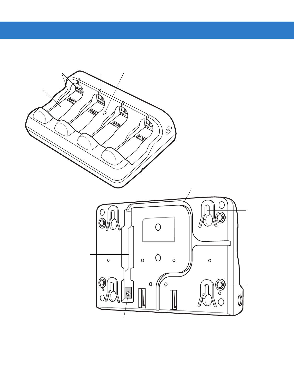
Four Slot Spare Battery Charger
Battery
Well
(four)
Battery
Charging LED
(four)
Battery
Charging
Contacts
Cradle
Power
LED
Wall Mount
Key-Hole (4)
Rubber Feet
(4)
Power Port
Power Cable
Groove
Cable Well
Getting Started 1 - 9
Figure 1-7
Four Slot Spare Battery Charger

1 - 10 MT2070/MT2090 User Guide
Host Interfaces
This device supports the following host interfaces through communication with a single slot multi-interface cradle:
•
Standard RS-232 connection to a host.
•
Keyboard wedge connection to a host, where scanned data is interpreted as keystrokes. The following
international keyboards are supported (for Windows™ environment): North American, German, French,
French Belgian, French Canadian, Spanish, Italian, Swedish, UK English, Japanese, and Brazilian
Portuguese (see Keyboard Wedge Country Types - Country Codes on page 11-5 for a full list).
•
IBM® 468X/469X hosts.
•
USB connection to a host. The device autodetects a USB host an d de fa u lts to th e HID ke yboa rd inte rf ace
type. Select other USB interface types by scanning programming bar codes. The following international
keyboards are supported (for Windows™ environment): North America, German, French, French Belgian,
French Canadian, Spanish, Italian, Swedish, UK English, Japanese, and Brazilian Portuguese (see
Country Keyboard Types - Country Codes
NOTE USB interface types can also be selected via the USB configuration menu on the device. To access the
USB configuration menu from the device’s Home screen, select Config... > Configure USB.
USB
on page 9-9 for a full list).
This device supports the following host interfaces without communication with a cradle:
•
Standard RS-232 connection to a host.
•
USB connection to a host via Bluetooth technology. The device autodetects a USB host and defaults to the
HID keyboard interface type. Select other USB interface types by scanning programming bar codes. The
following international keyboards are sup p or te d (f or Windows™ environment): North America, German,
French, French Belgian, French Canadian, Spanish, Italian, Swedish, UK English, Japanese, and Brazilian
Portuguese.
NOTE USB interface types can also be selected via the USB configuration menu on the device. To access the
USB configuration menu from the device’s Home screen, select Config... > Configure USB.
Out-of-Box Startup
To get the MT2070/MT2090 up and running:
•
Insert the rechargeable Li-ion battery
•
Connect power to the cradle.
•
Insert the device in the cradle.
•
Charge the device.
•
Configure the device.

Getting Started 1 - 11
Insert the Battery
The battery resides in a chamber in the device handle .
NOTE If the battery is completely discharged, and the unit is powered from a USB or RS232 cable, it may take up to
two hours for the unit to power up.There is no indication to the user of this condition and it may appear that the
unit is not charging and/or not working correctly. However, if the unit is placed in an STB2000 cradle with the
12V power supply power up is immediate.
To insert the battery:
1. Insert the battery into the battery well, top first, ensuring that the battery connectors touch the device
connectors inside the well.
CAUTION Avoid touching the contacts when positioning the battery.
2. Push down on the back of the battery until it snaps into place.
Figure 1-8
Battery Insertion
Connect the Cradle
IMPORTANT Connect the interface cable and power supply (if necessary) in the following order to ensure proper
operation of the device and cradle.
Connecting the STB20XX Cradle
1. Insert the host interface cable into the cradle's USB/host port. See Figure 1-2 on page 1-4 and Figure 1-5 on
page 1-7.
2. Connect the other end of the host interface cable to the host.
3. If necessary, connect the power supply to the cradle's power port (if the interface requires, or to allow fast
charging of the device).
4. Connect the appropriate cable to the power supply and an AC power source, if necessary.
5. If applicable, insert the power supply cable ferrite into the supp or t fea tu re s on the crad le bot tom an d ru n th e
host and power cables into their respective cable grooves.
6. For Bluetooth cradles only, pair the device to the cradle by scanning the pairing bar code on the cradle.

1 - 12 MT2070/MT2090 User Guide
7. If necessary, scan the appropriate host bar code (for non-autodetected interfaces). See the specific host
chapter.
NOTE Disconnect the power supply before changing host cables, or the device may not recognize the new host.
Different cables are required for different hosts. The connectors illustrated in each host chapter are examples
only. The connectors may be different from those illustrated, but the steps to connect the device remain the same
Connecting STB2000-F Cradle
1. Insert the host interface cable into the cradle's USB/host port. See Figure 1-2 on page 1-4.
2. Connect the forklift power supply to the cradle's power port, if applicable.
3. Optionally: Insert the power supply cable ferrite into the support features on the cr adle bottom and run the host
and power cables into their respective cable grooves, or use cable ties to secure them to the mounting plate
after attaching it to the cradle. For more information about mounting options and procedures, refer to the
documentation included with the cradle.
4. If necessary, scan the appropriate host bar code (for non-autodetected interfaces). See the specific host
chapter.
Changing the Host Interface
To connect to a different host, or to the same host using a different cable:
1. Disconnect the power supply from the cradle, if used.
2. Disconnect the interface cable from the host.
3. Connect the interface cable to the new host, or the new interface cable to the existing host.
4. Reconnect the power supply, if required.
5. If necessary, scan the appropriate host bar code (for non-autodetected interfaces). See the specific host
chapter.
CAUTION If the device does not recognize the host, disconnect the power supply, then reconnect after
connecting the host cable.
Supplying Power to the Cradle
The cradle receives power from one of two sources:
•
An external power supply.
•
When connected to the host through an interface cable that supplies power.
The cradle detects whether the host or the external supply is supplying power. It always draws power from the
external supply when available, regardless of the presence of power from a host.
Using the USB Interface to Supply Power
When the cradle is connected to the host via the USB interface, the USB port can power the cradle and a n external
power supply is not necessary. Note that powering from a USB host charges the device at a slower rate than
charging from an external power su pply. Additiona lly, dependin g on the level of activity, th e device may not charge
at all.

Insert the Device in the Cradle
1
2
1
2
1
2
?
?
To insert the device in the cradle:
1. Insert the device into the cradle top first.
2. Push the handle until it clicks into place, engaging the contacts in the cradle and device.
Getting Started 1 - 13
Figure 1-9
Inserting the Device in the Single Slot Cradles
NOTE When inserting the device in a wall mounted cradle, ensure the device’s hook recesses engage the hooks
on the wall mount adapter (when applicable).
Removing the Device from a Vertical Mount Cradle (Forklift or Wall Mount)
To remove the scanner from a vertically mounted cr adle, remove the bo ttom of the scanner first then gently p ull the
top of the scanner out of the cradle.
Charge the Device Battery in the Cradle
For best performance, fully charge the device battery before using the device for the first time. To charge the
device battery, place the device in the cradle (see Insert the Device in the Cradle on page 1-13). The batter y begins
charging when the device LED indicator starts flashing green. (With the exception of several initial charge cycles,
the default state of the LED is off when the battery is fully charged.) A complete charge of a fully discharged ba ttery
can take up to four hours using external power and up to 10 hours using the interface cable.
Charge within the recommended temperature of 32° to 104° F (0° to 40° C) nominal, 41° to 95° F (5° to 35° C)
ideal.
For information on maximizing battery life, see Battery on page 15-2.
NOTE The default state of the LED is off when the battery is fully charged with the exception of several initial
charge cycles. The LED may continually blink until the battery goes through several discharge cycles to
calibrate itself.
Charging Indicator/LED
The device has on screen charging indicators as well as an LED. The device’s flashing green LED indicates
charging activity.
If the device displays or indicating a charging problem, remove the device from the cradle and replace
the battery. If one of these icons continues to display, contact Zebra Support. See Screen Icons on page 2-9 for
descriptions of display icons.
Configure the Device
Use the bar codes in this manual to configure the device. See Chapter 5, User Preferences & Miscellaneous
Scanner Options, Chapter 6, Imaging Preferences and each host chap ter for information about programming the
device using bar code menus.

1 - 14 MT2070/MT2090 User Guide
Battery Charging
IMPORTANT 1) If the host PC is powered off, for example every night, the device continues to operate from its
battery until the battery is totally drained. Upon restart of the host PC, the device may not boot. The
battery has to charge at a reduced charge rate until the battery acquires sufficient charge to boot the
device. This can take up to two hours, depending on the level of discharge.
2) To prevent irreversible harm to battery do not store the device with the battery installed for
extended periods of time. For maximizing battery life, see Battery on page 15-2.
Charge the device using a cradle or host interface cable, or remove and charge the Li-ion battery using a spare
battery charger.
Before using the device for the first time, fully charge the Li-ion battery until the green LED on the device goes off
(default). The battery fully charges in less than four hours, when the device is placed in a cradle with a 12V supply
connected.
NOTE The default state of the LED is off when the battery is fully charged with the exception of several initial
charge cycles. The LED may continually blink until the battery goes through several discharge cycles to
calibrate itself.
This device does not have a backup battery. Any data in RAM is lost when the battery is removed. However, the
real-time clock is maintained for a period of 20 minutes during a battery change.
Use the following accessories to charge the Li-ion battery:
•
Cradles:
• Single Slot USB Charge Only Cradle - with power supply for fast charging
• Single Slot Multi-interface Bluetooth Cradle - with power supply; powered from host (slow charge)
• Four Slot Charge Only Cradle - with power supply
• Four Slot Ethernet Cradle - with power supply.
•
Spare Battery Charger:
• Four Slot Battery Charger - with power supply.
•
Cables (and a power supply):
• USB Client Charge Cable
• RS-232 Serial Cable - with power supply.
Use a cradle or a charge cable to charge the Li-ion battery in the device. Use either the four slot cradle or four slot
battery charger to charge up to four spare batteries. The charge cable requires a Zebra approved power supply.
•
Cradles
Insert the device into a cradle. See Chapter 13, Accessories for accessory setup. The device starts to charge
automatically. The charge LED on the device flashes during charging and goes off when the battery is fully
charged (default). See Table 13-2 for charging indications.
•
Cables
Connect a charge cable to the appropriate power source and connect the other end of the charge cable to
the device. See Chapter 13, Accessories for accessory setup. The device starts to charge automatically. The
charge LED on the device flashes during charging and goes off when the battery is fully charged (default).
See Table 13-2 for charging indications.
See Table 3-2 on page 3-3 for detailed scanning LED descriptions.

Battery Safety
IMPORTANT Battery safety depends on the proper selection and care of batteries.
Security Implementation/Protection From Counterfeit Batteries
Zebra devices are designed to work only with Zebra batteries. If you see a battery fault indication on the device
display, take the following steps:
•
Remove the battery and inspect it to confirm that it bears the Zebra name and/or logo.
•
If there is no Zebra name and/or logo, the battery is not a qualified battery.
•
If there is a Zebra name and/or logo, replace the bat ter y an d re tr y cha rg ing it.
•
If the message remains, contact a Zebra ser vice cen te r.
Zebra Battery Safety Recommendations For Users
IMPORTANT Handle and store batteries properly to avoid injury or damage.
Getting Started 1 - 15
Most battery issues arise from improper handling of batteries and particularly from the continued use of damaged
batteries.
•
Do not disassemble, crush, puncture, shred or otherwise attempt to change the form of the battery.
•
Do not let the device or battery come in contact with water. Water can get into the circuits, leading to
corrosion. If the device and/or battery get wet, have them checked by your administrator or contact Zebra
even if they appear to be working properly.
•
Do not allow the battery to touch metal objects. If metal objects stay in prolonged contact with the battery
contact points, the battery could become very hot.
•
Do not place the battery near a heat source. Excessive heat can damage the device or the battery. High
temperatures can cause the battery to swell, leak or malfunction. Therefore:
• Do not dry a wet or damp battery with an appliance or heat source, such as a hair dryer or microwave
oven.
• Avoid leaving the device in areas of high temperatures.
•
Do not drop the battery or device. Dropping these items, especially on a hard surface, can potentially cause
damage.
•
Contact your service provider or Zebra if your device or battery was damaged from drop ping or as a resu lt of
exposure to high temperatures.
IMPORTANT Use only Zebra-branded batteries and chargers.
WARNING! Use of a non-Zebra battery or charger may present a risk of fire, explosion, leakage or other
hazard.
Proper and Safe Battery Disposal & Recycling
Proper battery disposal is not only important for safety, it also benefits the environment. Promptly dispose of used
batteries in accordance with local regulations. Contact your local recycling center or national recycling
organizations for more information on how to dispose of batteries.
Additional information on proper disposal and recycling may be found on the Web at:
www.zebra.com/recycling and
www.rbrc.org/call2recycle/.

1 - 16 MT2070/MT2090 User Guide
Sending Data to the Host Computer
Out of the box, the device supports two modes to send data to a host computer: via cable (RS-232 or USB); and
via Bluetooth (open/paired with an STB2078 cradle).
Cable Mode
Via cable (RS-232 or USB) the user interface indicates the active mode for transmitting bar code data to the host.
•
A displays on the screen when bar code data transmits via USB.
•
An displays on the screen when bar code data transmits via RS-232.
Bluetooth Mode
In Bluetooth mode (open or cradle), a Bluetooth icon displays on the screen when bar code data tr ansmits via
Bluetooth.
The cradle receives data from the device via a wireless radio connection and transmits it to the host computer via
the host cable. The device and cradle must be paired for successful wireless communication.
Pairing
Pairing registers a device to the cradle such that the device and cradle can exchange information. The cradles
operate in two modes: Point-to-Point and Multipoint-to-Point. In Point-to-Point mode, pair the device to the cradle
either by inserting it in the cradle (if pairing on insertion is enabled), or by scanning the pairing bar code. In
Multipoint-to-Point mode, you can pair up to seven devices to one cradle. To use this feature, scan the multipoint
bar code in Multipoint-to-Point Communication on page 4-19.
The cradle includes pairing bar codes on both its front and back. To pair the device with the cradle, scan a pairing
bar code. A high-low-high-low beep sequence followed by a low-high beep sequence indicates successful pairing
and connection to the remote device. A long low, long high beep sequence indicates unsuccessful pairing.
NOTE The pairing bar code that connects the device to a cradle is unique to each cradle.
Do not scan data or parameters until pairing completes.
Lost Connection to Host
If scanned data does not transmit to the cradle's host, ensure that all cables are firmly inserted and the power
supply is connected to an appropriate AC outlet, if applicable. If scanned data still does not transmit to the host,
reestablish a connection with the host:
1. Disconnect the power supply from the cradle.
2. Disconnect the host interface cable from the cradle.
3. Wait three seconds.
4. Reconnect the host interface cable to the cradle.
5. Reconnect the power supply to the cradle, if the host requires.
6. Reestablish pairing with the cradle by scanning the pairing bar code.
Radio Communications
The device can communicate with remote devices via Bluetooth Technology Profile Support, or by pairing with a
cradle. For radio communication parameters, detailed information about operational modes, Bluetooth Technology
Profile Support and pairing, see Chapter 4, Radio Communications.

Startup
MT2000
series
When the device is powered on for the first time, it initializes. Th e splash screen a ppears for a short p eriod of time .
If the device does not power on, see Resetting the Device on page 1-17.
Getting Started 1 - 17
Figure 1-10
Splash Screen
Suspending/Powering Off the Device
A suspend menu item is accessible from Home screen. On the Home screen, press Menu > Suspend.
Resetting the Device
See Resetting the MT20X0 on page 2-106.
Turning the WLAN Radio On and Off
See Enable/Disable Radio on page 2-92.
Waking the Device
See Waking the MT20X0 on page 2-107.

1 - 18 MT2070/MT2090 User Guide
Battery lock
Battery Removal
To remove the battery:
1. Press Menu >Suspend to turn off the screen and place the device in suspend mode.
2. With your thumb, press down on the indentation on the battery lock and drag it away from the battery.
3. Lift up the back of the battery and pull it out of the battery well.
Figure 1-11
Li-ion Battery Removal
WARNING! The device is not water sealed when the battery is removed.
Spare Battery Charging
Use the Spare Battery charger to charge spare Li-ion batteries. See to Chapter 13, Accessories for more
information on spare battery charging.
Screen Protector
For added protection from scratches the device includes a protective film over the display window. It is
recommended you leave this on for added scratch resistance.

Lanyard
To install the optional lanyard:
1. Insert the loop on the lanyard into the slot at the bottom of the de vice .
Getting Started 1 - 19
Figure 1-12
2. Thread the upper portion of the lanyard into the loop.
Figure 1-13
3. Pull the clip through the loop over the tether point and tighten into place.
Insert Lanyard Loop
Thread the Loop
Figure 1-14
Insert Loop into Tether Point

1 - 20 MT2070/MT2090 User Guide

Chapter 2 Operating the MT2070/MT2090
Introduction
This chapter provides instructions for using and navigating the device.

2 - 2 MT2070/MT2090 User Guide
Right soft and CTRL key
4-way Navigation
(Up, Down, Right, Left)
Backspace and ESC key
Cold boot trigger
Enter key
Orange key
Left soft and
ALT key
Tab and * key
Blue key
Keypad
The keypad contains alphanumeric characters, scroll keys, function keys and an ENT (Enter) key. The keypad is
color-coded to indicate the alternate function keys (blue and orange). Note that an application can change the
keypad functions so the device's keypad may not function exactly as described. SeeTable 2-1 on page 2-3 for key
descriptions.
Figure 2-1
NOTE The device does not have a Power key. To suspend the device go to Home screen; press the left soft key
ALT
TAB
F
F
4
F
7
GHI
PQRS
F
ABC
2
JKL
F
5
F
TUV
8
0
MT2070/MT2090 Keypad
(Menu); scroll to Suspend; press ENT.
CTRL
ESC
DEF
F
3
MNO
F
6
WXVZ
F
9
ENT

Keypad Functionality
ALT
TAB
F
NOTE The keypad functionality described in Table 2-1 does not necessarily apply to all configurations of the
MT20X0.
Operating the MT2070/MT2090 2 - 3
Table 2-1
Keypad Functionality
Key Description
Left Soft Key, ALT Defaults to the left soft key which initiates the action noted
on the bottom left of the screen (usually a menu option);
ALT key when the Blue function key is enabled.
Right Soft Key; CTRL Defaults to the right soft key which initiates the action
CTRL
noted on the bottom right of the screen; CTRL key when
the Blue function key is enabled.
Up, Down, Left, Right Defaults to Scroll key allowing up, down, left, right
navigation.
Tab Defaults to TAB key; asterisk (*) when the Blue function
key is enabled.
Depending on the screen display, TAB moves from pane
to pane in the contents section of a multipane display.
Backspace, ESC Defaults to backspace; ESC when the Blue function key is
ESC
enabled.
Depending on the screen display:
Returns to the previous level in the display.
Closes the menu and returns to the previous screen.
Clears a highlighted field.
Press Blue
Press Orange
Key
ALT N/A
CTRL N/A
N/A N/A
* N/A
ESC N/A
Key
F1, 1, special characters Defaults to the number 1; F1 when the Blue function key
is enabled; characters . , - when the
Orange
is enabled.
* See
Keypad Multi-tap Configuration on page 2-7
.
F1 . , -
function key

2 - 4 MT2070/MT2090 User Guide
F
2
ABC
F
4
GHI
Table 2-1
Keypad Functionality (Continued)
Key Description
*
F2, 2, A, B, C, a, b, c
*
F3, 3, D, E, F, d, e, f
DEF
F
3
Defaults to the number 2; F2 when the Blue function key
is enabled; A, B, C, a, b, c when the
Orange
function key
is enabled.
In alpha mode (enable Orange function key), the number
of key presses determines the letter and case.
1 key press = a
2 key presses = b
3 key presses = c
4 key presses = A
5 key presses = B
6 key presses = C
Defaults to the number 3; F3 when the Blue function key
is enabled; D, E, F, d, e, f when the Orange function key is
enabled.
In alpha mode (enable Orange function key), the number
of key presses determines the letter and
case.
1 key press = d
2 key presses = e
3 key presses = f
4 key presses = D
5 key presses = E
6 key presses = F
Press Blue
Key
Press Orange
Key
F2 a, b, c, A, B, C
F3 d, e, f, D, E, F
*
F4, 4, G, H, I, g, h, i
Defaults to the number 4; F4 when the Blue function key
is enabled; G, H, I, g, h, i when the Orange function key is
enabled.
In alpha mode (enable Orange function key), the number
of key presses determines the letter and case.
1 key press = g
2 key presses = h
3 key presses = i
4 key presses = G
5 key presses = H
6 key presses = I
* See
Keypad Multi-tap Configuration on page 2-7
F4 g, h, i, G, H, I
.

Operating the MT2070/MT2090 2 - 5
5
F
JKL
6
F
MNO
F
7
PQRS
Table 2-1
Keypad Functionality (Continued)
Key Description
*
F5, 5, J, K, L, j, k, l
*
F6, 6, M, N, 0, m, n, o
Defaults to the number 5; F5 when the Blue function key
is enabled; J, K, L, j, k, l when the Orange function key is
enabled.
In alpha mode (enable Orange function key), the number
of key presses determines the letter and case.
1 key press = j
2 key presses = k
3 key presses = l
4 key presses = J
5 key presses = K
6 key presses = L
Defaults to the number 6; F6 when the Blue function key
is enabled; M, N, 0, m, n, o when the Orange function key
is enabled.
In alpha mode (enable Orange function key), the number
of key presses determines the letter and case.
1 key press = m
2 key presses = n
3 key presses = o
4 key presses = M
5 key presses = N
6 key presses = O
Press Blue
Key
Press Orange
Key
F5 j, k, l, J, K, L
F6 m, n, o, M, N, 0
*
F7, 7, P, Q, R, S, p, q, r, s
Defaults to the number 7; F7 when the Blue function key
is enabled; P, Q, R, S, p, q, r, s when the Orange function
key is enabled.
In alpha mode (enable Orange function key), the number
of key presses determines the letter and case.
1 key press = p
2 key presses = q
3 key presses = r
3 key presses = s
4 key presses = P
5 key presses = Q
6 key presses = R
7 key presses = S
* See
Keypad Multi-tap Configuration on page 2-7
F7 p, q, r, s, P, Q,
R, S
.

2 - 6 MT2070/MT2090 User Guide
8
F
TUV
0
Table 2-1
Keypad Functionality (Continued)
Key Description
*
F8, 8, T, U, V, t, u, v
*
F9, 9, W, X, Y, Z, w, x, y,
z
WXVZ
F
9
Defaults to the number 8; F8 when the Blue function key
is enabled; T, U, V, t, u, v when the Orange function key is
enabled.
In alpha mode (enable Orange function key), the number
of key presses determines the letter and case.
1 key press = t
2 key presses = u
3 key presses = v
4 key presses = T
5 key presses = U
6 key presses = V
Defaults to the number 9; F9 when the Blue function key
is enabled; W, X, Y, Z, w, x, y, z when the Orange function
key is enabled.
In alpha mode (enable Orange function key), the number
of key presses determines the letter and case.
1 key press = w
2 key presses = x
3 key presses = y
4 key presses = W
5 key presses = X
6 key presses = Y
Press Blue
Key
Press Orange
Key
F8 t, u, v, T, U, V
F9 w, x, v, z, W, X,
V, Z
Home, 0, space Defaults to the number 0; Displays the Home screen
when the Blue function key is enabled; space when the
Orange function key is enabled.
The Home key returns to the Home screen.
The space ( ) can be used to:
•
select/clear check boxes
•
select an item.
* See
Keypad Multi-tap Configuration on page 2-7
]
.
Home
Note:
Under most
circumstances
pressing the
Home key brings
the Navigator
application to the
foreground.
However, Home
key functionality
depends upon the
current screen
display.
This key cannot
be programmed.
Space

Operating the MT2070/MT2090 2 - 7
Table 2-1
ENT Press ENT (Enter) to launch an application or select a
Orange Press this key once to enable the orange alpha and
Blue Press this key once to enable functionality of ALT, CTRL,
Keypad Functionality (Continued)
Key Description
ENT
current/highlighted item.
Depending on the screen, press Enter to:
•
close a display and return to the previous screen.
•
lock in an entered quantity and highlight an item field.
•
store data from an item field.
•
to edit a highlighted item.
special character keys. Press the key again to disable
alpha and special character keys and return to default key
use.
When enabled, a filled orange circle displays (see
Screen Icons on page 2-9
orange key functionality is disabled.
*, ESC or a function key. When enabled, an empty blue
circle displays (see
When no circle displays, blue key functionality is disabled.
). When no circle displays,
Screen Icons on page 2-9
).
Press Blue
Key
N/A N/A
N/A N/A
N/A N/A
Press Orange
Key
* See
Keypad Multi-tap Configuration on page 2-7
Keypad Multi-tap Configuration
In alpha mode (when the
lower case first. For example, multi-taps of the 2 key displays 'a', 'b', 'c', 'A', 'B', 'C', lower case first.
The multi-tap sequence can be changed by modifying the Multitap.reg file under the "\Platform" directory on the
device.
For detailed information, refer to the MT2070/MT2090 Integrator Guide, p/n 72E-117858-xx.
.
Orange function key is
enabled/
tapped) t
he default sequence of multi-tapping a key is

2 - 8 MT2070/MT2090 User Guide
Using the Keypad to Navigate Applications
The screen is a non-touch screen. Navigation and control of an application is performed using the keypad.
Entering Information
To enter information:
•
Use the keypad.
•
Scan bar code data into data fields.
•
Use Microsoft® ActiveSync® to synchronize or copy information from the host computer to the device. For
more information on ActiveSync, refer to the MT2070/MT2090 Integrator Guide (part number
72E-117858-xx).
Entering Information Using the Keypad
The alphanumeric keypads produce the 26-character alphabet (A-Z), numbers (0-9), function keys and assorted
characters. The keypads’ default charac ters/functions are printed white, the alpha character/functions are printed
orange and the function character/functions are printed blue. See Keypad on page 2-2 for keypad configurations.

Screen Icons
Operating the MT2070/MT2090 2 - 9
Table 2-2
Icon Description
Battery
Icons
Critical low battery (< 5% full); recharge.
Battery fault.
Battery fault; AC power applied. Low battery; recharge.
Low battery; recharge.
Battery is 25% full.
Battery is 50% full.
Battery is 75% full.
Battery is fully charged.
Low battery; charging using AC power source.
Battery 25% full; charging using AC power source.
Battery 50% full; charging using AC power source.
Battery 75% full; charging using AC power source.
Battery is fully charged; AC power source connected.

2 - 10 MT2070/MT2090 User Guide
Table 2-2
Connections
Keypad Functionality
Icons (Continued)
Icon Description
Bluetooth is inactive (STB2078 cradle only).
Bluetooth is active (STB2078 cradle only).
RS-232 connection is active.
USB connection is active.
One time blue key functionality (see
Blue on page 2-7
).
Unlimited orange key functionality (see
Wireless Signals (MT2090 Only)
No wireless signal or not associated.
Very low signal.
Low signal. Medium signal.
Medium signal.
Good signal.
Excellent signal.
Orange on page 2-7
).

Home Screen
MT2070
MT2090
When the device powers on, the first screen to display is the Home screen. This screen also launches when you
press the Home key (see Home, 0, space on page 2-6).
Operating the MT2070/MT2090 2 - 11
Figure 2-2
Table 2-3 lists the options available on the Home screen. Use the Up or Down Scroll key to highlight an option in
the list and press ENT to launch the screen.
Table 2-3
Scan Item On this screen the user can, scan, display and transmit bar code data. See page 2-17.
Scan Inventory On this screen the user can enter inventory information and send it to a local file in the Windows
Simple Inventory This is a batch inventory application similar to Scan Inventory. It differs in that it transmits data
ScanToIP The Scan-to-IP application allows you to scan directly to a host PC using your existing WiFi
MCL (MT2070 Only) The MCL application on the device is a simple scanning application which performs scanning
Image Viewer On this screen the user can preview, snap and save images. See page 2-39.
Home Screen Options
Option Description
Home Screen
CE file system. See page 2-20.
into the MT as scanned. For example, it does not alphabetize or group same bar codes. See
page 2-26.
network. The application is pre loaded on newer MT2090 devices and can be downloaded from
the Web to older models.See page 2-32.
and sending bar codes to a host computer. See page 2-35.

2 - 12 MT2070/MT2090 User Guide
Table 2-3
Config... On this screen the user has access to the following features:
Utilities... On this screen the user has access to the following features:
Menu This menu provides access to User Settings, Device Status, Battery Status and an About
Home Screen Options (Continued)
Option Description
•
Wireless Companion - see page 2-41.
•
Settings - see page 2-93.
•
Rapid Deployment - see page 2-93.
•
MSP Agent - see page 2-94.
•
BTExplorer - see page 2-95.
•
Configure USB - see page 2-102.
•
File Explorer
•
Task Manager.
See page 2-104.
screen. See page 2-13.
Menu
The Home screen Menu provides access to User Settings, Device Status, Battery Status and an About screen.
Press the Up or Down Scroll key to select an option. Press ENT to display the appropriate screen.
Figure 2-3
Home Screen Menu

Operating the MT2070/MT2090 2 - 13
User Settings
On this screen, make adjustments for the device’s beeper, backlight and time. Press the Up or Down Scroll key to
select an option.
Figure 2-4
•
•
•
Figure 2-5
Scroll to the appropriate line.
•
User Settings Screen
Beeper Volume: Scroll to Beeper Volume and press the right or left Scroll key to choose a Low, Medium or
High beeper volume. Press the right soft key (Done) to save changes and end the session.
Beeper Frequency: Scroll to Beeper Frequency and press the right or left Scroll key to choose a Low,
Medium or High beeper frequency. Press the right soft key (Done) to save changes and end the session.
Backlight: Scroll to Backlight and press ENT to display the Backlight screen.
Backlight Screen
Brightness: Use the right or left Scroll key to choose a brightness level for the display.
•
Battery Timeout: Using the keypad, enter a numeric value to set the seconds in which the backlight turns off
when the device is exclusively using battery power.
•
AC Timeout: Using the keypad, enter a numeric value to set the seconds in which the backlight turns off
when the device is not powered exclusively by battery power.
•
Press the right soft key (Done) to save changes and end the session.

2 - 14 MT2070/MT2090 User Guide
•
Date and Time: With Date and Time highlighted, press ENT to display the Date and Time screen.
Figure 2-6
•
•
•
Press the right soft key (OK) to save changes and end the session.
Press the left soft key (Cancel) to end the session without saving cha ng e s.
•
Figure 2-7
Date and Time Screen
Press TAB to toggle between Date: and Time: fields.
Press the right or left Scroll key to move to sub-fields within Date: and Time:.
Press the Up or Down Scroll key to change values.
Time Zone: With Time Zone highlighted, press ENT to display the Time Zone screen.
Time Zone Screen
•
Press TAB to toggle between Time Zone: and Auto adjust fields.
•
Press the Up or Down Scroll key to change the time zone.
•
Press the Space key (see Space key on page 2-6) to check/uncheck the Auto adjust box. Press the right soft
key (OK) to save changes and end the session.
Press the left soft key (Cancel) to end the session without saving cha ng e s.

Operating the MT2070/MT2090 2 - 15
Device Status
This screen displays information about the device: model, serial number, Blueto oth, MAC address and ADCSvcs
version.
Figure 2-8
Device Status Screen
NOTE MAC: field applies to the MT2090 only.
Battery Status
This screen displays the device’s battery information.
Figure 2-9
Battery Status Screen
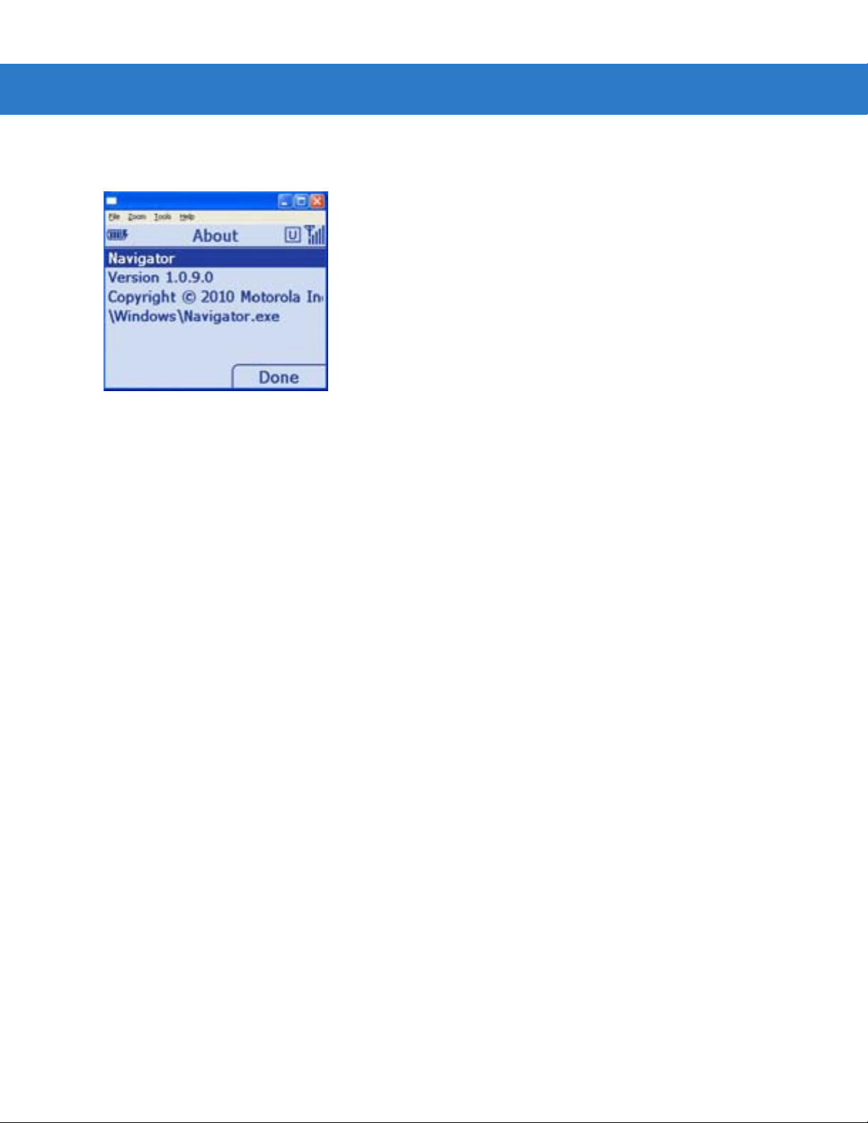
2 - 16 MT2070/MT2090 User Guide
About
This screen displays version and copyright information.
Figure 2-10
About Screen
Suspend
On the Home screen (see Figure 2-2 on page 2-11) press Menu > Suspend to place the d evice in sleep mode. To
wake the device, press any key.

Scan Item
The Scan Item screen allows the user to transmit bar code data to the host PC. To access Scan Item, start at the
Home screen, scroll to Scan Item and press ENT.
Operating the MT2070/MT2090 2 - 17
Figure 2-11
The following options are available:
•
•
•
•
Scan Item Screen
Scan a bar code. The data displays briefly in the Item: field and the bar code data transmits to the host PC
(Quantity defaults to a value of one and transmits one bar code.)
Key an SKU or bar code data manually using the keyboard. Press ENT to transmit the data to the host PC.
(Quantity defaults to a value of one and transmits one SKU or bar code.)
Press the up Scroll key to access t he Quantity field; enter a quantity using the ke yboard. Scan a ba r code ( or
enter an SKU/bar code manually and press ENT). The data transmits x times, where x = the quantity entered,
with a programmable delay between each transmit.
Select Menu > Options... to set the transmit format (see Menu on page 2-18).
Quantity
Enter the quantity of SKUs or bar code data to transmit to the host PC (1 to 99999). Quantity defaults to a value of
one and transmits one bar code.
Item
The Item: field is highlighted by default. Scan a bar code or use the numeric keys to manually enter an SKU or bar
code. The default symbology type is Code 128.

2 - 18 MT2070/MT2090 User Guide
Transmit: Separate
Transmit: Together
Menu
Press the left soft key to display the Menu.
Figure 2-12
Scan Item Screen - Menu
Options
Scroll to Options... and press ENT to display the options screen to set transmit bar code data options.
Figure 2-13
•
Scan Item Screen - Menu - Options
Transmit: When you enter a quantity of two or more on the Scan Item screen, scroll to Transmit: in this
display and press the left or right scroll key to select how to transmit bar code data - Together or
Separate.
•
Delimiter: When you select to transmit bar code data Together, the Delimiter: field displays. Scroll to this
•
Delay: When you select to transmit Separate bar code data, scroll to Delay: and enter the time in
•
Barcode: Scroll to Barcode: to choose a symbology type - Code 128 or Code 39.
•
Clear Delay:The number of seconds a bar code clears after transmission.
•
Cancel: Press to cancel settings and return to previous screen.
•
Done: Press to save settings and return to previous screen.
field and press the left or right scroll key to choose a delimiter method - comma, semi-colon or
tab.
milliseconds to separate the transmission of data.

About...
Displays information about the ScanItem application.
Close
Press the right soft key to close the screen and return Home.
Close
Scroll to Close and press ENT to exit and return Home.
Operating the MT2070/MT2090 2 - 19

2 - 20 MT2070/MT2090 User Guide
Scan Inventory
The Scan Inventory screen allows the user to enter inventory information and send it to a local file in the Windows
CE file system. Set the file type in which to save the inventory data in Menu > Options screen > Format: (see
Figure 2-16 on page 2-21).
To access Scan Inventory, start at the Home screen, scroll to Scan Inventory and press ENT.
Figure 2-14
When the Scan Inventory screen displays for the first time, the cursor defaults to the Quantity field. If a quantity is
required, it must be entered prior to scanning or entering data in the Item: field. Use the Up or Down Scroll key to
move from one field to another. Enter data as necessary.
Scan Inventory Screen - Default View
Location
Use the keypad to enter a location. Location is an eight character alphanumeric field. Press the orange key to
enable the alpha keypad; press the orange key again to enable the numeric keypad. When the alpha keypad is
enabled and orange circle appears on the bottom of the screen.
Figure 2-15
Scan Inventory Screen - Location
The device remembers the location entered throughout the session, until it is changed and stores as the default
location in location.xml.

Operating the MT2070/MT2090 2 - 21
Quantity
Quantity defaults to a value of one to transmit one bar code to the host PC.
Scroll to Quantity and use the keypad to enter the quantity of SKUs or bar code data to transmit to the host PC (1
to 99999).
IMPORTANT Quantity must be entered prior to scanning or entering data in the Item: field.
Item
Scroll to Item and scan a bar code or use the keypad to enter an SKU or bar code to transmit to the host PC. The
data displays on the screen for 3 seconds or less with a trigger or key press. The default symbology type is Code
128.
Menu
Press the left soft key to display the Menu.
Figure 2-16
Scan Inventory Screen - Menu
View Inventory
Scroll to View Inventory and press ENT to display a list of the saved inventory items stored in the device. Each ro w
in the list includes location, quantity and bar code/SKU.
The current inventory stores in a .txt or .xml file located in the Applications/Inventory folder. If no inventory items
were saved, the file does not exist and no contents d isplay. If the file does exist, the items display in a li st view with
column headers for location, item and quantity.
The View Inventory screen has several menu options for maintaining information saved in the inventory file.

2 - 22 MT2070/MT2090 User Guide
View Inventory Menu
The View Inventory menu includes several options to maintain and customize inventory data. On the View
Inventory screen press the left soft key to display the menu items. Press the Up or Down Scroll key to select an
option. Press ENT to display the appropri at e sc re e n.
Figure 2-17
•
View Inventory Menu
Edit
Ensure the item to edit is highlighted on the View Inve ntory screen, then press Menu > Edit. On the Edit Item
screen (Figure 2-18) edit the inventory data as needed (scanning is disabled in this view and data must be
edited manually). Press TAB to move from field to field. Use the keypad to edit the information in each field.
NOTE By default the orange key is not active in the Edit Item window. If necessary, press the orange key to
enable/disable the alpha key pad.
Press the left soft key (Cancel) to cancel the edits and return to the View Inventory screen. Press the right
soft key (OK) to save the edits.
Figure 2-18
Edit Item Screen

Operating the MT2070/MT2090 2 - 23
•
Delete Item
Ensure the item to delete is highlighted on the View Inventory screen, then press Menu > Delete Item... . The
following confirmation dialog displays. Press the left soft key (No) to cancel the delete and return to the View
Inventory screen. Press the right soft key (Yes) to delete the selected inventory item.
Figure 2-19
•
Figure 2-20
•
Selecting Transmit sends data to the host PC via the configured interface and protocol (such as USB HID
keyboard).
Delete Item Dialog
Delete All
On the View Inventory screen, press Menu > Delete All... . The following confirmation dialog displays. Press
the left soft key (No) to cancel the delete and retu rn t o the View Inventory screen. Press the right soft key
(Yes) to delete all inventory items listed.
Delete All Dialog
Transmit
On the View Inventory screen, press Menu > Transmit to send data.
NOTE Data is not deleted after transmission.

2 - 24 MT2070/MT2090 User Guide
•
Export
Exporting formats data in a user friendly layout which can be downloaded from the device. On the View
Inventory screen, press Menu > Export. The dialog in Figure 2-21 displays indicating the path of the file to be
exported to the Application folder on the device. The default file name and type is export.txt. Press ENT to
export all data and return to the View Inventory screen.
Figure 2-21
•
Figure 2-22
•
Export Dialog
NOTE The export format, text or XML, is specified in Options... on page 2-25.
Save
Saving data ensures that data is not lost during a warm or cold boot. For example, when the user inserts a
new battery in the device, a save is recommended prior to switching batteries. On the View Inventory screen,
press Menu > Save. The following dialog displays indicating a successful save. Press ENT to accept the
save and return to the View Inventory screen.
Save Dialog
Options
On the View Inventory screen, press Menu > Options.
Save Inventory
Scroll to Save and press ENT to save the data to the location specified in the Options dialog.

Operating the MT2070/MT2090 2 - 25
Options...
Scroll to Options and press ENT to configure the inventory application. On this screen, set the file format and the
file storage location to save data. The format is specified in an xml file located in the folder \application\inventory.
Press the Up or Down Scroll key to move from field to field. Use the keypad to enter a value in the File: field; Press
the right or left Scroll key to change the data within all other fields.
Figure 2-23
•
•
•
•
•
•
•
Options Screen
File: Specify a file type.
Format: Specify a Text of XML file format.
Separator: Specify a delimiter (comma, semi-colon or tab).
Grouped: Currently not implemented.
Clear Delay:The time in seconds data is automatically cleared from the display after scanning.
Cancel: Press to canc el set tin gs and return to previous screen.
Done: Press to save settings and return to previous screen.
About...
Displays information about the ScanInventory application.
Close
Scroll to Close and press ENT to exit and return Home.

2 - 26 MT2070/MT2090 User Guide
Simple Inventory
Similar to Scan Inventory, the Simple Inventory screen allows the user to enter and transmit inventory information.
It differs from Scan Inventory in that it transmits data the same way the data is scanned into the MT. For example, if
the user scans bar codes 123, 456, ABC, 123, 012, ABC in this order, the application transmits the bar codes to the
host in the same order:
123
456
ABC
789
123
012
ABC
Same data is not grouped or alphabetized.
To access Simple Inventory, start at the Home screen, scroll to Simple Inventory and press ENT.
Figure 2-24
Simple Inventory Screen - Default View
Item
When the Simple Inventory screen displays for the first time, the cursor de fa ults to the Item: field. Scan a bar code
or use the keypad to enter an SKU or bar code to transmit to the host PC. The default symb ology type is Code 128.
Quantity
If a quantity is required, it must be entered prior to scanning o r entering data in th e Item: field. Use the Up or Down
Scroll key to move from one field to another. Enter data as necessary.
Quantity defaults to a value of one to transmit one bar code to the host PC.
Scroll to Quantity and use the keypad to enter the quantity of SKUs or bar code data to transmit to the host PC (1
to 99999).
IMPORTANT Quantity must be entered prior to scanning or entering data in the Item: field.

Menu
Press the left soft key to display the Menu.
Operating the MT2070/MT2090 2 - 27
Figure 2-25
Simple Inventory Screen - Menu
Transmit
Selecting Transmit sends data to the host PC via the configured interface and protocol (such as USB HID
keyboard).
On the Simple Inventory screen, press Menu > Transmit > ENT to send data.
NOTE Data is not deleted after transmission.
View Inventory
Scroll to View Inventory and press ENT to display a list of the saved inventory items stored in the device. Each ro w
in the list includes location, quantity and bar code/SKU.
The current inventory stores in a .txt or .xml file located in the Applications/Inventory folder. If no inventory items
were saved, the file does not exist and no contents d isplay. If the file does exist, the items display in a li st view with
column headers for location, item and quantity.
The View Inventory screen has several menu options for maintaining information saved in the inventory file.

2 - 28 MT2070/MT2090 User Guide
View Inventory Menu
The View Inventory menu includes several options to maintain and customize inventory data. On the View
Inventory screen press the left soft key to display the menu items. Press the Up or Down Scroll key to select an
option. Press ENT to display the appropri at e sc re e n.
Figure 2-26
•
Figure 2-27
View Inventory Menu
Delete Item
Ensure the item to delete is highlighted on the View Inventory screen, then press Menu > Delete Item... . The
following confirmation dialog displays. Press the left soft key (No) to cancel the delete and return to the View
Inventory screen. Press the right soft key (Yes) to delete the selected inventory item.
Delete Item Dialog

Operating the MT2070/MT2090 2 - 29
•
Delete All
On the View Inventory screen, press Menu > Delete All... . The following confirmation dialog displays. Press
the left soft key (No) to cancel the delete and retu rn t o the View Inventory screen. Press the right soft key
(Yes) to delete all inventory items listed.
Figure 2-28
•
•
Delete All Dialog
Transmit
Selecting Transmit sends data to the host PC via the configured interface and protocol (such as USB HID
keyboard).
On the Simple Inventory screen, press Menu > Transmit > ENT to send data.
NOTE Data is not deleted after transmission.
Export
Exporting formats data in a user friendly layout which can be downloaded from the device. On the View
Inventory screen, press Menu > Export. The dialog in Figure 2-21 displays indicating the path of the file to be
exported to the Application folder on the device. The default file name and type is export.txt. Press ENT to
export all data and return to the View Inventory screen.
Figure 2-29
•
Export Dialog
NOTE The export format, text or XML, is specified in Options... on page 2-25.
Save
Saving data ensures that data is not lost during a warm or cold boot. For example, when the user inserts a
new battery in the device, a save is recommended prior to switching batteries. On the View Inventory screen,

2 - 30 MT2070/MT2090 User Guide
press Menu > Save. The following dialog displays indicating a successful save. Press ENT to accept the
save and return to the View Inventory screen.
Figure 2-30
•
Save Dialog
Options
On the View Inventory screen, press Menu > Options.
Save Inventory
Scroll to Save and press ENT to save the data to the location specified in the Options dialog.
Options...
Scroll to Options and press ENT to configure the inventory application. On this screen, set the file format and the
file storage location to save data. The format is specified in an xml file located in the folder \application\inventory.
Press the Up or Down Scroll key to move from field to field. Use the keypad to enter a value in the File: field; Press
the right or left Scroll key to change the data within all other fields.
Figure 2-31
•
•
•
•
•
Options Screen
File: Specify a file type.
Format: Specify a Text of XML file format.
Clear Delay:The time in seconds data is automatically cleared from the display after scanning.
Cancel: Press to canc el set tin gs and return to previous screen.
Done: Press to save settings and return to previous screen.

About...
Displays information about the ScanInventory application.
Close
Scroll to Close and press ENT to exit and return Home.
Operating the MT2070/MT2090 2 - 31

2 - 32 MT2070/MT2090 User Guide
Scan-To-IP
The Scan-to-IP screen allows the user to scan directly to a host PC using your existing wireless network. The
application should be pre loaded on the MT2090 device
NOTE Scan-to-IP may not be loaded on older devices. In this case, download the application to your PC;
establish an ActiveSync connection; run ScanToIpDeviceInstaller.exe to download it to the MT 2090.
The host application must be installed on your PC or terminal host.
Setup
•
Install the host application on your PC or terminal host. Visit http://www.scan-to-ip.com to download both th e
Windows host application and the device installer, if necessary.
•
Run the host application, ScanToIp.exe, from the Scan-to-IP folder on the PC or terminal host.
•
To access Scan-To-IP, start at the Home screen, scroll to Scan-To-IP and press ENT.
.
Figure 2-32
•
Figure 2-33
Scan-To-IP Option on Home Screen
Click the Setup tab. Press the right soft key to display the Setup.
Scan-To-IP Screen

•
Enter the Host (IP) address, or keep the default setting.
•
Press TAB to Enter the Host port no., or keep the default setting.
Operating the MT2070/MT2090 2 - 33
Figure 2-34
•
Terminal Host Setup Screen
Click Create pairing barcode and print the bar code (imager units can scan the monitor).
Figure 2-35
Host Application - PC Setup Screen

2 - 34 MT2070/MT2090 User Guide
•
Scan the bar code to pair with the host PC/server (print and scan the bar code or for imager units, scan the
bar code directly on the monitor).
Figure 2-36
•
The device installer can also be used to:
•
•
•
If you have problems or questions, select FAQ at http://www.scan-to-ip.com
Scan-to-IP Pair Bar Code
The host application and the MT2090 device should now be paired.
Configure the WLAN settings
Configure scanner settings
Buy and activate an advanced license for additional features.
.
Suspend
Press the left soft key to suspend the device. (Press any key to wake the suspended device.)

MCL
Operating the MT2070/MT2090 2 - 35
When you select MCL from the Home screen, the MCL-Client loads and the MCL program which loaded on the
device runs.
Figure 2-37
By default, the MCL application on the device is a simple scanning application which performs scanning and
sending bar codes to a host computer, and scanning inventory with a timestamp.
MCL-Collection is an intuitive, high-productivity software tool used to create, integrate and deploy enterprise ,
multimodal mobile worker applications quickly and easily. From bar code sca nni ng a nd da ta ca ptur e o n device s to
ODBC, WMS, or SAP R/3 connectivity on the host, MCL-Collection provides seamless integration from the
computer to host application.
For more information refer to the MCL Technologies Start Up Guide for the MT2000 at:
http://www.mcl-collection.com
When the MCL-Client loads, the Main Menu screen of the default MCL program loads. On this screen, select the
mode (Scan Transmit on page 2-36 or Scan Inventory on page 2-37) of the MCL default scanning application.
MCL-CIient Load - Typical View
NOTE The MCL client is pre-licensed on the MT2070 only. The MCL client on the MT2090 requires an activated
license to run.
.
Figure 2-38
MT2000 Default Application Home Screen - Typical View

2 - 36 MT2070/MT2090 User Guide
Scan Transmit
When Scan Transmit is selected on the Main Menu, the Scan & Send screen displays. On this screen the user can
manually enter a quantity and scan data to a computer using a tethered cable or a Bluetooth connection via the
STB2078 cradle.
Figure 2-39
•
•
NOTE On the first transmit; the application establishes communication with MCL link which may take several
Scan & Send Screen
: Use the keypad to enter a quantity into this field. Scanning is disabled when this field is highlighted.
: Scan a bar code to enter data into this field. After scanning data, the quantity and data are sent to
MCL Link.
seconds.

Operating the MT2070/MT2090 2 - 37
Scan Inventory
When Scan Inventory is selected on the Main Menu, the Scan Inventory screen displays (Figure 2-40). On this
screen the user must enter the location in which the inventory is scanned. When a location is not entered, two short
beeps sound indicating an error.
1. Use the keypad to enter a location and press ENT to continue.
Figure 2-40
2. Upon pressing ENT, the Scan screen displays.
Figure 2-41
3. : Use the keypad to enter a quantity into this field. Scanning is disabled when this field is highlighted.
4. : Scan a bar code to enter data into this field. Scanned data in this screen is stored on the FFS file
Scan Inventory Screen
Scan Inventory Scan Screen
system and can be viewed, deleted, or transmitted to MCL Link.

2 - 38 MT2070/MT2090 User Guide
5. Use the right soft key to select MENU. The Inventory Menu displays.
Figure 2-42
6. Select the appropriate option and press the right soft key (OK) to perform the appropriate action (View Data,
Send Data, Delete Last).
Inventory Menu Screen
View Data
The View Data screen provides a list of all scanned data including the location, item, quantity, date and time. On
this screen, press the right soft key to display menu options to edit a selected record, delete a selected record or
delete all records.
Figure 2-43
View Data Screen
Send Data
Select this option to transmit scanned data to the host PC MCL Link application.
Delete Last
Select this option to delete the last item scanned.

Image Viewer (Devices Equipped with Imagers)
The Image Viewer screen allows the user to preview, snap and save images.
To access Imager Sample, start at the Home screen, scroll to Imager Sample and press ENT
Operating the MT2070/MT2090 2 - 39
Figure 2-44
Image Viewer Screen
Menu
Press the left soft key to display the Menu.
Figure 2-45
Preview On
Scroll to Preview On and press ENT to display a preview of an image. Point the scan window at the image and
press the scan trigger to take a picture.
Image Viewer Screen - Menu
Open
Scroll to Open and press ENT to display the File Explorer. Press the Up or Down Scroll key to find an image and
press ENT to display it.

2 - 40 MT2070/MT2090 User Guide
Options
Scroll to Options and press ENT to display the Options screen. Press the up or down Scroll key to selec t an opti on
to edit and press ENT.
Figure 2-46
•
•
•
Options Screen
JPEG Quality: Picture quality indicator. Higher numbers produce better quality pictures and larger file sizes).
Illumination: Press the right and left scroll keys to turn illumination On or Off. The default is Off. Depending
on the room lighting, an image captured by the device may appear too dark. The illumination
feature allows you to adjust the lighting on the snapshot target.
Preview Aim: Laser emits when the trigger is pulled.
About
Displays information about the Imager demo application.
Close
Press the right soft key to close the screen and return Home.

Config
MT2070 MT2090
Operating the MT2070/MT2090 2 - 41
To access Config, start at the Home screen, scroll to Config... and press ENT.
Figure 2-47
Config... Screens
Wireless Companion (MT2090 Only)
NOTE Some screens and windows pictured in this section are samples and can differ from actual screens.
The Wireless Companion is used to configure and ma nage th e device’s wireless networ k settings. On the Config...
screen press the up or down Scroll key to highlight Wireless Companion and press ENT to display the Wireless
Companion menu.
Figure 2-48
Config... Wireless Companion Menu

2 - 42 MT2070/MT2090 User Guide
Find WLANs
On the Wireless Companion menu, press the up or down Scroll key to highlight Find WLANs and press ENT to
display the Find WLANs screen.
Figure 2-49
The Find WLANs list displays:
•
•
•
•
Highlight a network in the list and press ENT to open a pop-up menu which provides two options:
Connect and Refresh. Select Refresh to refresh the WLAN list. Select Connect to create a WLAN profile from that
network (see Manage Profiles on page 2-42). This opens the Profile Entry screen which allows you to set the
values for the selected network. After editing the pr of ile, the device automatically connects to this new profile.
Find WLANs Screen
WLAN Networks:Available wireless networks.
Network Type: Type of network. 802.11(a), 802.11(b) or 802.11(g).
Channel: Channel on which the AP is transmitting.
Signal Strength: The signal strength of the signal from the AP.
Manage Profiles
The Manage Profiles screen provides a list of user-configured wireless profiles. Define up to 32 profiles at any one
time.
On the Wireless Companion menu, press the up or down Scroll key to highlight Manage Profiles and p ress ENT to
display the Manage Profiles screen.
Figure 2-50
Manage Profiles Screen

Icons next to each profile identify the profiles current state.
Operating the MT2070/MT2090 2 - 43
Table 2-4
Icon Description
No Icon Profile is not selected, but enabled.
The profiles are listed in priority order for use by the automatic roaming feature. Change the order by moving
profiles up or down. Edit existing profiles by selecting one in the list and then pressing ENT to display the menu.
The menu allows the selected profile to be connected, edited, disabled (enabled) or deleted. (Note: the
menu item changes to
Profile Icons
Profile is disabled.
Profile is Cancelled. A Cancelled profile is disabled until a connect or login functio n is performed through
the configuration editor.
Profile is currently in use and describes an infrastructure profile not using encryption.
Profile is currently in use and describes an infrastructure profile using encryption.
Profile is currently in use and describes an ad-hoc profile not using encryption.
Profile is currently in use and describes an ad-hoc profile using encryption.
Profile is not valid in the device current operating regulatory domain.
Disable
Enable if the profile is already disabled.)
A dialog displays to confirm the users desire to delete a profile, if selected.
Changing Profiles
A completed profile is a set of configuration settings that can be used in different locations to connect to a wireless
network. Create different profiles to have pre-defined operating parame ters available for use in various network
environments. When the Manage Profiles screen displays, existing profiles appear in the list.
To change an existing profile, highlight a prof ile on the Manage Profiles screen, press ENT to display the menu,
scroll to Edit and press ENT.
Creating a New Profile
Creating a new profile allows the user to configure profile name, ESSID, security, network addre ss information and
the power consumption level.

2 - 44 MT2070/MT2090 User Guide
Profile ID
Press the up or down Scroll key on the profile menu and select Add. The Profile Entry dialog displays.
Figure 2-51
Profile Entry Screen
Profile Name
The name and (WLAN) identifier of the network connection. Enter a user friendly name for the device profile used
to connect to either an AP or another networked device. Example: The Public LAN.
NOTE Two profiles with the same user friendly name are acceptable but not recommended.
ESSID
The ESSID is the 802.11 extended service set identifier. The ESSID is 32-character (maximum) case sensitive
string identifying the WLAN and must match the AP ESSID for the device to communicate with the AP.
Tab to Next > and press ENT to move to the Operating Mode dialog.
Operating Mode
Figure 2-52
2-33 Operating Mode/Country Screen

Operating the MT2070/MT2090 2 - 45
Operating Mode
Select the operating mode (Infrastructure or Ad-Hoc) from the Operating Mode: drop-down list. The operating
mode Infrastructure enables the device to transmit and receive data with an AP. Infrastructure is the default mode.
Table 2-5
Operating Mode Fields
Field Description
Operating Mode Infrastructure: Select
Infrastructure
to enable the device to transmit and receive data with an AP.
Infrastructure is the device default mode.
Ad Hoc: Select
communicate peer-to-peer without APs using a shared ESSID.
Ad Hoc
to enable the device to form its own local network where devices
If Ad-Hoc mode was selected,
see Channel on page 2-46. If Infrastructure mode was selected, see Security Mode on page
2-47
Country Country: is used to determine if the profile is valid for the country o f operation. The profile country
must match the country in the options. page or it must match the acquired country if 802.11d is
enabled.
Single Country Use:
When the device is only to be used in a single country, set every profile country to
Country
. In the
Options
>
Regulatory
dialog box (see
Figure 2-99 on page 2-77
Allow Any
), set the country to
the specific country the device is to be used in, and deselect (uncheck) the Enable 802.11d
option. This is the most common and the efficient configuration. It eliminates the initialization
overhead associated with acquiring a country via 802.11d.
Multiple Country Use:
When the device may be used in more than one country, select (check) the Enable 802.11d
option in the
need for reprogramming the country (in
Regulatory Options
dialog box (see
Options
Figure 2-99 on page 2-77
>
Regulatory
) each time a new country is entered.
). This eliminates the
However, this only works if the infrastructure (i.e. APs) support 802.11d (some i nfrastruct ures do
not support 802.11d, including some Cisco APs). When the Enable 802.11d option is selected,
the
Options
>
Regulatory
>
Country
setting is not used. For a single profile that can be used in
multiple countries, with infrastructure that supports 802.11d (including Symb ol infrastructure), set
the Profile Country to
Options
>
Regulatory
Allow Any Country
>
Country
setting is not used.
. Under
Options
>
Regulatory
, select
Enable 802.11d
. The
For a single profile that can be used in multiple countries, but with infrastructure that does not
support 802.11d, set the profile country to
802.11d
. In this case, the
Options
>
Regulatory
Allow Any Country
>
Country
setting must always be set to the country
, and de-select (uncheck)
Enable
the device is currently in. This configuration option is the most efficient and may be chosen for
use with any infrastructure. However, the
Options
>
Regulatory
>
Country
setting must be manually
changed when a new country is entered.
(continued)
Tab to Next > and press ENT to move to the next dialog.

2 - 46 MT2070/MT2090 User Guide
Channel
If Ad-Hoc mode was selected the Ad-Hoc Channel dialog displays.
Figure 2-53
Ad-Hoc - Channel Screen
Use the Ad-Hoc Channel dialog to configure the required information to create an Ad-Hoc pr ofile. T his dialog d oes
not appear if you selected Infrastructure mode. Select a channel number from the Channel drop-down list.
NOTE In the case of a country where DFS is implemented in band 5150-5250 MHz, Ad-hoc is not allowed and
the user needs to move and select a channel in the 2.4 GHz band.
NOTE Ad-hoc channels are specific to the country selected.
Table 2-6
Ad-Hoc Channels
Band Channel Frequency
2.4 GHz 1 2412 MHz
2
3
4
5
6
2417 MHz
2422 MHz
2427 MHz
2432 MHz
2437 MHz
7
8
9
10
11
2442 MHz
2447 MHz
2452 MHz
2457 MHz
2462 MHz

Security Mode
If Infrastructure mode was selected the Security Mode dialog displays.
Operating the MT2070/MT2090 2 - 47
Figure 2-54
Infrastructure - Security Mode/Authentication Type

2 - 48 MT2070/MT2090 User Guide
Security Mode
Use the Security Mode dialog to configure the Security and Authentication methods. If Ad-Hoc mode is selected,
this dialog is not available and authentication is set to None by default.
Select the security mode from the Security Mode drop-down list. The selection chosen affects the availability of
other choices for Authentication Type and Encryption methods.
•
LEGACY (Pre-WPA):This mode allows the user to configure protocols not available in the other Security
Mode selections: Open authentication / encryption; Open au thentication with WEP 40
or WEP 128; and 802.1X authentications that use WEP128 Encryption.
•
WPA-Personal: This mode allows the user to configure a WPA-TKIP-PSK protocol.
•
WPA2-Personal This mode allows the user to configure WPA2-PSK protocols with the Advanced
Encryption Standard (AES) encryption method.
•
WPA-Enterprise: This mode allows the user to configure profiles with 802.1X Authentica tion that uses
WPA and TKIP encryption method.
•
WPA2-Enterprise: This mode allows the user to configure profiles with 802.1X Authentication that uses
WPA2 with AES encryption method.
Table 2-7
Security Mode
Legacy (Pre-WPA) None,
WPA - Personal None TKIP Enabled. User input required with pass-phrase/hex key
WPA2 - Personal None AES Enabled. User input required with pass-phrase/hex key
WPA - Enterprise EAP-TLS,
WPA2 - Enterprise EAP-TLS,
Security Modes
Authentication
EAP-TLS,
EAP-FAST,
PEAP,
LEAP,
TTLS
EAP-FAST,
PEAP,
LEAP,
TTLS
EAP-FAST,
PEAP,
LEAP,
TTLS
Types
Encryption Types Pass-phrase/Hexkey Configuration
Open,
WEP-40 (40/24),
WEP-104 (104/24),
TKIP,
AES
TKIP Disabled. No user input required for encryption key.
AES Disabled. No user input required for encryption key.
Enabled. User input required with pass-phrase/hex key
configuration.
configuration.
configuration.

Operating the MT2070/MT2090 2 - 49
Authentication Type
Select an available authentication type from the drop-down list. The options listed in the drop-down list are based
on the selected Security Mode as shown in Table 2-8.
The authentication types, other than None, all use IEEE 802.1x authentication to ensure that only valid users and
sometimes servers can connect to the network. Each authentication type uses a different scheme using various
combinations of tunnels, username/passwords, user certificates, server certificates and Protected Access
Credentials (PACs).
Table 2-8
Authentication Description
None Use this setting when authentication is not required on the network.
EAP-TLS Select this option to enable EAP-TLS authentication. A user certificate is requir ed; validati ng the
EAP-FAST Select this option to enable EAP-FAST authentication. This type uses a PAC (Protected Access
PEAP Select this option to enable PEAP authent ication. This type esta blishes a tunnel and then based
LEAP Select this option to enable LEAP authentication. This type does not establish a tunnel. It
TTLS Select this option to enable TTLS authentication. This type establishes a tunnel and then based
Authentication Options
server certificate is optional.
Credential) to establish a tunnel and then uses the selected tunnel type to verify credentials.
PACs are handled behind the scenes, transparently to the user. Automatic P AC provisioning can,
depending on the tunnel type, require a user certificate and the validation of a server certificate.
Manual PAC provisioning is currently not supported.
on the tunnel type, uses a user certificate and/or a username/password. Validating the server
certificate is optional.
requires a username and password.
on the tunnel type, uses a user certificate and/or a username/password. Validating the server
certificate is optional.
Tab to Next > and press ENT. Selecting PEAP, TTLS or EAP-FAST displays the Tunneled Authentication Type
dialog. Selecting None displays the Encryption dialog. Selecting EAP-TLS displays the Installed User Certs dialog.
Selecting LEAP displays the User Name dialog.
Tunneled Authentication
Use the Tunneled Authentication Type dialog to select the tunneled authentication options. The content of the
dialog differs depending on the Authentication Type chosen.
Figure 2-55
Tunneled Authentication Dialog Box

2 - 50 MT2070/MT2090 User Guide
To select a tunneled authentication type:
1. Select a tunneled authentication type from the drop-down list. See Table 2-9 for the Tunnel Authentication
options for each authentication type.
2. Select the User Certificate check box if a certificate is required. If the TLS tunnel type that requires a user
certificate is selected, the check box is already selected.
3. Tab to Next > and press ENT. The Installed User Certificates dialog displays.
Table 2-9
Tunneled Authentication Options
Authentication Type
Tunneled
Authentication
DescriptionPEAP TTLS EAP-FAST
CHAP X Challenge Handshake Authentication Protocol (CHAP) is one of the two
main authentication protocols used to verify the user name and
password for PPP Internet connections. CHAP is more secure than
PAP because it performs a three way handshake during the initial link
establishment between the home and remote machines. It can also
repeat the authentication anytime after the link is established.
EAP-GTC X X EAP-GTC is used during phase 2 of the authentication process. This
method uses a time-synchronized hardware or software token
generator, often in conjunction with a user PIN, to create a one-time
password.
MD5 X Message Digest-5 (MD5) is an authentication algorithm developed by
RSA. MD5 generates a 128-bit message digest using a 128-bit key,
IPSec truncates the message digest to 96 bits.
MS CHAP X Microsoft Challenge Handshake Authentication Protoc ol ( MS CHAP) is
an implementation of the CHAP protocol that Microsoft created to
authenticate remote Windows workstations. MS CHAP is identical to
CHAP, except that MS CHAP is based on the encryption and hashing
algorithms used by Windows networks and the MS CHAP response to
a challenge is in a format optimized for compatibility with Windows
operating systems.

Operating the MT2070/MT2090 2 - 51
Table 2-9
Authentication
MS CHAP v2 X X X Microsoft Challenge Handshake Authentication Protocol version 2 (MS
PAP X Password Authentication Protocol (PAP) has two variations: PAP and
Tunneled Authentication Options (Continued)
Authentication Type
Tunneled
DescriptionPEAP TTLS EAP-FAST
CHAP v2) is a password-based, challenge-response, mutual
authentication protocol that uses the industry-standard Message Diges t
4 (MD4) and Data Encryption Standard (DES) algorithms to encrypt
responses. The authenticating server challenges the access client and
the access client challenges the authenticating server. If either
challenge is not correctly answered, the connection is rejected. MS
CHAP v2 was originally designed by Microsoft as a PPP authentication
protocol to provide better protection for dial-up and virtual private
network (VPN) connections. With Windows XP SP1, Windows XP SP2,
Windows Server 2003 and Windows 2000 SP4, MS CHAP v2 is also an
EAP type.
CHAP PAP. It verifies a user name and password for PPP Internet
connections, but it is not as secure as CHAP, since it works only to
establish the initial link. PAP is also more vulnerable to attack because
it sends authentication packets throughout the network. Nevertheless,
PAP is more commonly used than CHAP to log in to a remote host like
an Internet service provider.
TLS X X EAP TLS is used during phase 2 of the authentication process. This
method uses a user certificate to authenticate.
User Certificate Selection
If the user checked the User Certificate check box on the Tunneled Authentication dialog or if TLS is the selected
authentication type, the Installed User Certificates dialog displays. Select a certificate from the drop-down list of
currently installed certificates before proceeding. The selected certificate’s name appears in the drop-down list. If
the required certificate is not in the list, install it.
Figure 2-56
Installed User Certificates Dialog Box

2 - 52 MT2070/MT2090 User Guide
User Certificate Installation
There are two methods available to install a user certificate for authentication. The first is to obtain the user
certificate from the Certificate Authority (CA). This requires connectivity with that CA. The second method is to
install the user certificate from a file that was placed on the device.
To install a user certificate from the CA:
1. Tab to Install Certificate and press ENT. The Import Certificate dialog displays.
Figure 2-57
2. Select Import User Cert from Server and select OK. The Install from Server dialog displays.
Figure 2-58
3. Enter the User:, Password: and Server: information in their respective text boxes.
4. Tab to Retrieve. A Progress dialog indicates the status of the certificate retrieval, or tab to Exit and press ENT.
Import Certificate Dialog Box
Install from Server Dialog Box
After the installation completes, the Installed User Certs dialog displays and the certificate is available in the
drop-down for selection.
NOTE To successfully install a user certificate, the device must already be connected to a network from which
the server is accessible.

Operating the MT2070/MT2090 2 - 53
To install a user certificate from a file:
1. Tab to Install Certificate and press ENT. The Import Certificate dialog displays.
Figure 2-59
2. Choose Import from File and select OK. The Open dialog displays.
Figure 2-60
3. In the Type drop-down list, select Personal Certs (*.pfx).
4. Browse to the file and select OK. The Personal Certificate dialog displays.
Import Certificate Dialog Box
Open Dialog Box
Figure 2-61
Personal Certificate Screen

2 - 54 MT2070/MT2090 User Guide
5. Enter the password and select OK. The certificate(s) are imported.
NOTE Installing a user certificate from a file requires that the file be of type “*.pfx”. Also this file type requires the
user to supply a password in order to be read by Fusion.
Server Certificate Selection
If the user selects the Validate Server Certificate check box, a server certificate is required.
Select a certificate from the drop-down list of currently installed certificates in the Installed Server Certificates
dialog. An hour glass may appear as the wizard populates the existing certificate list. If the required certificate is
not listed, install it.
Figure 2-62
Installed Server Certificates Dialog Box
Server Certificate Installation
To install a server certificate for authentication:
1. Tab to Install Certificate and press ENT. The Import Certificate dialog displays. Choose Import from File (.cer,
.pfx) and select OK.
Figure 2-63
Import Certificates Dialog Box

Operating the MT2070/MT2090 2 - 55
2. A dialog displays that lists the certificate files found with the default extension.
Figure 2-64
3. Browse to the file and select OK.
4. A confirmation dialog verifies the installation. If the information in this dialog is correct, select Yes. If the
Open Screen
information in this dialog is not correct select No. The wizard returns to th e Installed Server Certs dialog. Select
the newly-installed certificate from the drop-down list.
Figure 2-65
Confirmation Dialog Box
User Name
The user name and password can be entered (but is not required) when the profile is created. If the userna me and
password are not entered in the profile, then when attempting to connect, the user is be prompted to supply them.
The entered information (credentials) is saved (cached) for future reconnections.
Whether or not the username and password are entered into the profile affects how the profile is treated during a
Profile Roaming operation. Profiles are excluded from consideration if they require user entry of credential
information.
If the profile uses an authentication tunnel type of EAP-GTC and Token is selected (see Password on page 2-56),
then you can control certain behavior by whether you choose to enter a value in the Enter User Name field. If you
enter a value in the Enter User Name field, then whenever the Fusion software prompts you to enter credentials,
the username field in the interactive credential dialog is initialized with the value that you entered when you created
the profile. If you enter a different value in the username field of the interactive credential dialog, it is cached and
used to initialize the username field the next time the interactive credential dialog is shown for that profile. If you do
not enter a value in the Enter User Name field when you create an EAP-GTC token profile, then the username field
in the interactive credential dialog is initialized to blank. After you enter a username in the interactive credential

2 - 56 MT2070/MT2090 User Guide
dialog, it is cached as usual, but it is not be used to initialize the username field the next time the interactive
credential dialog is shown for that profile; the username field is initialized to blank. In summary, the user can control
whether the username field in the interactive credential dialog is initialized, either with the last-interactively-entered
username for that profile or with the username entered into the profile, by whether any value is entered in the Ent er
User Name field during profile entry.
Figure 2-66
Username Dialog Box
Password
Use the Password dialog to enter a password. If EAP/TLS is the selected authentication type, the password dialog
does not display. Note that if a username was entered and no password is entered, Fusion assumes that no
password is a valid password.
Figure 2-67
1. Enter a password in the Enter Password field. If an authentication tunnel type of EAP-GTC is used, a
Password dialog with additional radio buttons displays.
Password Dialog Box
Figure 2-68
EAP-GTC Password Dialog Box
 Loading...