


9160 G2
Wireless Gateway
User Manual
December 17, 2020 Part No. 8100117 Rev D
ISO 9001 Certified
Quality Management System

© Copyright 2007 by Psion Teklogix Inc., Mississauga, Ontario
This document and the information it contains is the property of Psion Teklogix Inc.,
is issued in strict confidence, and is not to be reproduced or copied, in whole or in
part, except for the sole purpose of promoting the sale of Psion Teklogix manufactured goods and services. Furthermore, this document is not to be used as a basis for
design, manufacture, or sub-contract, or in any manner detrimental to the interests of
Psion Teklogix Inc.
Windows® and the Windows Logo are trademarks or registered trademarks of
Microsoft Corporation in the United States and/or other countries.
All trademarks are the property of their respective holders.

Return-To-Factory Warranty
Psion Teklogix Inc. provides a return to factory warranty on this product for a period
of twelve (12) months in accordance with the Statement of Limited Warranty and
Limitation of Liability provided at www.psionteklogix.com/warranty. (If you are not
already a member of Teknet and you attempt to view this warranty, you will be
asked to register. As a member of Teknet, you will have access to helpful information about your Psion Teklogix products at no charge to you.) In some regions, this
warranty may exceed this period. Please contact your local Psion Teklogix office for
details. For a list of offices, see Appendix A: “Support Services And Worldwide
Offices”. The warranty on Psion Teklogix manufactured equipment does not extend
to any product that has been tampered with, altered, or repaired by any person other
than an employee of an authorized Psion Teklogix service organization. See Psion
Teklogix terms and conditions of sale for full details.
Important: Psion Teklogix warranties take effect on the date of shipment.
Service
Psion Teklogix provides a complete range of product support services to its customers. For detailed information, please refer to Appendix A: “Support Services And
Worldwide Offices”. This section also provides information about accessing support
services through the Psion Teklogix web site.
Waste Electrical and Electronic Equipment (WEEE) Directive 2002/96/EC
This Product, and its accessories, comply with the requirements of the Waste Electrical and Electronic Equipment (WEEE) Directive 2002/96/EC. If your end-of-life
Psion Teklogix product or accessory carries a label as shown here, please contact
your local country representative for details on how to arrange recycling.
For a list of international subsidiaries, please go to:
www.psionteklogix.com/EnvironmentalCompliance
Restriction On Hazardous Substances (RoHS) Directive 2002/95/EC
What is RoHS?
The European Union has mandated that high environmental standards be met in the
design and manufacture of electronic and electrical products sold in Europe, to
reduce hazardous substances from entering the environment. The “Restriction on
Hazardous Substances Directive (RoHS)” prescribes the maximum trace levels of

lead, cadmium, mercury, hexavalent chromium, and flame retardants PBB and PBDE
that may be contained in a product. Only products meeting these high environmental
standards may be “placed on the market” in EU member states after July 1, 2006.
RoHS Logo
Although there is no legal requirement to mark RoHS-compliant products, Psion
Teklogix Inc. indicates its compliance with the directive as follows:
The RoHS logo located either on the back of the product or underneath the battery in
the battery compartment (or on a related accessory such as the charger or docking
station) signifies that the product is RoHS-compliant as per the EU directive. Other
than as noted below, a Psion Teklogix product that does not have an accompanying
RoHS logo signifies that it was placed on the EU market prior to July 1, 2006, and is
thereby exempt from the directive.
Note: Not all accessories or peripherals will have a RoHS logo due to physical
space limitations or as a result of their exempt status.
Disclaimer
Every effort has been made to make this material complete, accurate, and up-to-date.
In addition, changes are periodically added to the information herein; these changes
will be incorporated into new editions of the publication.
Psion Teklogix Inc. reserves the right to make improvements and/or changes in the
product(s) and/or the program(s) described in this document without notice, and
shall not be responsible for any damages, including but not limited to consequential
damages, caused by reliance on the material presented, including but not limited to
typographical errors.

TABLE OF CONTENTS
Approvals and Safety Summary ..........................xiii
Chapter 1: Introduction
1.1 About This Manual..............................3
1.2 Online Help Features, Supported Browsers, And Limitations ........6
1.3 Text Conventions . . .............................7
1.4 Overview Of The 9160 G2 Wireless Gateway ................8
1.4.1 Radios...................................8
1.4.2 Access Point Functions..........................10
1.4.3 Base Station Functions..........................10
1.4.4 Mini-Controller Functions.........................11
1.5 Features and Benefits.............................11
1.5.1 IEEE Standards Support And Wi-Fi Compliance. . . ..........11
1.5.2 Wireless Features.............................11
1.5.2.1 The Psion Teklogix 802.IQ Protocol . ................12
1.5.3 Security Features .............................13
1.5.4 Out-of-the-Box Guest Interface......................13
1.5.5 Clustering And Auto-Management....................14
1.5.6 Networking................................14
1.5.7 SNMP Support . .............................15
1.5.8 Maintainability ..............................15
1.6 What’s Next?.................................15
Chapter 2: Installation Requirements
2.1 Choosing The Right Location........................19
2.1.1 Environment................................19
2.1.2 Maintenance................................20
2.1.3 Radios...................................20
Psion Teklogix 9160 G2 Wireless Gateway User Manual i

Contents
2.1.4 Power And Antenna Cables.......................20
2.1.4.1 Power ................................20
2.1.4.2 Antennas...............................21
2.2 Connecting To External Devices......................22
2.2.1 Ports...................................23
2.2.2 LAN Installation: Overview.......................23
2.2.3 LAN Installation: Ethernet........................24
2.2.3.1 Ethernet Cabling...........................24
2.2.3.2 100Base-FX Fiber Optic Ethernet Port...............24
2.2.4 Status Indicators (LEDs).........................25
2.2.5 Connecting A Video Display Terminal .................25
2.3 Changing The Configuration With A Web Browser............26
Chapter 3: PreLaunch Checklist
3.1 The 9160 G2 Wireless Gateway . . . ................... 29
3.1.1 Default Settings For The 9160 G2 Wireless Gateway..........29
3.1.2 What The Access Point Does Not Provide ...............32
3.2 Administrator’s Computer .........................32
3.3 Wireless Client Computers.........................33
3.4 Understanding Dynamic And Static IP Addressing On The 9160 G2 Wireless
Gateway...................................34
3.4.1 How Does The Access Point Obtain An IP Address At Startup?....34
3.4.2 Dynamic IP Addressing.........................35
3.4.3 Static IP Addressing...........................35
3.4.4 Recovering An IP Address........................36
Chapter 4: Quick Steps For Setup And Launch
4.1 Unpack The 9160 G2 Wireless Gateway .................. 39
4.1.1 9160 G2 Wireless Gateway Hardware And Ports ............ 39
4.1.2 What’s Inside The 9160 G2 Wireless Gateway?. ............ 39
4.2 Connect The Access Point To Network And Power............ 40
4.2.1 A Note About Setting Up Connections For A Guest Network ..... 42
4.2.1.1 Hardware Connections For A Guest VLAN. ............42
4.3 Power On The Access Point ........................42
ii
Psion Teklogix 9160 G2 Wireless Gateway User Manual

Contents
4.4 Log On To The Administration Web Pages.................42
4.4.1 Viewing Basic Settings For Access Points................43
4.5 Configure ‘Basic Settings’ And Start The Wireless Network........44
4.5.1 Default Configuration...........................44
4.6 What’s Next?.................................44
4.6.1 Make Sure The Access Point Is Connected To The LAN.........45
4.6.2 Test LAN Connectivity With Wireless Clients..............45
4.6.3 Secure And Fine-tune The Access Point Using Advanced Features . . .45
Chapter 5: Configuring Basic Settings
5.1 Navigating To Basic Settings.........................49
5.2 Review / Describe The Access Point.....................50
5.3 Provide Network Settings ..........................51
5.4 Update Basic Settings ............................52
5.5 Basic Settings For A Standalone Access Point................52
5.6 Your Network At A Glance: Understanding Indicator Icons.........52
Chapter 6: Managing Access Points & Clusters
6.1 Overview...................................57
6.2 Navigating To Access Points Management .................57
6.3 Understanding Clustering ..........................58
6.3.1 What Is A Cluster?............................58
6.3.2 How Many APs Can A Cluster Support? . ................58
6.3.3 What Kinds Of APs Can Cluster Together?................58
6.3.4 Which Settings Are Shared As Part Of The Cluster Configuration And
Which Are Not?..............................59
6.3.4.1 Settings Shared In The Cluster Configuration............59
6.3.4.2 Settings Not Shared By The Cluster .................60
6.3.5 Cluster Formation.............................60
6.3.6 Cluster Size And Membership ......................60
6.3.7 Intra-Cluster Security ...........................61
6.4 Understanding Access Point Settings ....................61
6.4.1 Modifying The Location Description...................62
6.4.2 Setting The Cluster Name.........................62
Psion Teklogix 9160 G2 Wireless Gateway User Manual iii

Contents
6.5 Starting Clustering .............................63
6.6 Stopping Clustering .............................63
6.7 Navigating To Configuration Information For A Specific AP And Managing
Standalone APs...............................64
6.7.1 Navigating To An AP By Using Its IP Address In A URL.......64
6.8 Session Monitoring.............................64
6.8.1 Navigating to Session Monitoring....................64
6.8.2 Understanding Session Monitoring Information............. 65
6.8.3 Viewing Session Information for Access Points.............67
6.8.4 Sorting Session Information.......................67
6.8.5 Refreshing Session Information.....................67
Chapter 7: Managing User Accounts
7.1 Overview..................................71
7.2 Navigating To User Management......................72
7.2.1 Viewing User Accounts.........................72
7.2.2 Adding A User..............................73
7.2.3 Editing A User Account.........................73
7.2.4 Enabling And Disabling User Accounts .................74
7.2.5 Enabling A User Account........................74
7.2.6 Disabling A User Account........................75
7.2.7 Removing A User Account .......................75
7.3 Backing Up And Restoring A User Database................75
7.3.1 Backing Up The User Database..................... 75
7.3.2 Restoring A User Database From A Backup File ............75
Chapter 8: Channel Management
8.1 Navigating To Channel Management.................... 79
8.2 Understanding Channel Management....................79
8.2.1 How It Works In A Nutshell....................... 80
8.2.2 For The Curious: More About Overlapping Channels . . . ......80
8.2.3 Example: A Network Before And After Channel Management.....80
8.3 Configuring And Viewing Channel Management Settings.........81
8.3.1 Stopping/Starting Automatic Channel Assignment ........... 82
iv
Psion Teklogix 9160 G2 Wireless Gateway User Manual

Contents
8.3.2 Viewing Current Channel Assignments And Setting Locks.......83
8.3.2.1 Update Current Channel Settings (Manual)..............83
8.3.3 Viewing Last Proposed Set Of Changes . ................83
8.3.4 Configuring Advanced Settings (Customizing And Scheduling Channel
Plans)...................................84
8.3.4.1 Update Advanced Settings......................86
Chapter 9: Wireless Neighborhood
9.1 Navigating To Wireless Neighborhood....................89
9.2 Understanding Wireless Neighborhood Information. . . ..........89
9.3 Viewing Wireless Neighborhood.......................90
9.4 Viewing Details For A Cluster Member...................92
Chapter 10: Configuring Security
10.1 Understanding Security Issues On Wireless Networks ...........97
10.1.1How Do I Know Which Security Mode To Use?.............97
10.1.2 Comparison Of Security Modes For Key Management, Authentication And
Encryption Algorithms..........................98
10.1.2.1When To Use Unencrypted (No Security)..............98
10.1.2.2When To Use Static WEP.......................99
10.1.2.3 When To Use IEEE 802.1x .....................100
10.1.2.4When To Use WPA Personal ....................101
10.1.2.5When To Use WPA Enterprise ...................102
10.1.3Does Prohibiting The Broadcast SSID Enhance Security?.......103
10.1.4How Does Station Isolation Protect The Network?...........104
10.2 Configuring Security Settings .......................104
10.2.1Broadcast SSID, Station Isolation, And Security Mode ........105
10.2.2Security Modes.............................106
10.2.2.1None (Plain-text) ..........................106
10.2.2.2Static WEP.............................107
10.2.2.3 IEEE 802.1x. ............................112
10.2.2.4WPA Personal ...........................114
10.2.2.5WPA Enterprise ...........................117
10.3 Updating Settings..............................120
Psion Teklogix 9160 G2 Wireless Gateway User Manual v

Contents
Chapter 11: Maintenance And Monitoring
11.1 Interfaces . . . ...............................123
11.1.1Ethernet (Wired) Settings........................124
11.1.2Wireless Settings.............................124
11.2 Event Logs .................................124
11.2.1Enabling Or Disabling Persistence....................125
11.2.2Severity..................................126
11.2.3Depth...................................126
11.2.4Log Relay Host For Kernel Messages..................127
11.2.4.1 Understanding Remote Logging...................127
11.2.4.2Setting Up The Log Relay Host...................127
11.2.4.3 Enabling Or Disabling The Log Relay Host On The Status,
Events Page.............................128
11.2.5Events Log................................129
11.3 Transmit/Receive Statistics .........................130
11.4 Associated Wireless Clients.........................131
11.4.1Link Integrity Monitoring........................132
11.5 Neighboring Access Points .........................132
Chapter 12: The Ethernet (Wired) Interface
12.1 Navigating To Ethernet (Wired) Settings..................139
12.1.1DNS Hostname..............................140
12.1.2Guest Access...............................140
12.1.2.1Configuring An Internal LAN And A Guest Network .......140
12.1.2.2Enabling Or Disabling Guest Access................141
12.1.2.3Specifying A Virtual Guest Network................141
12.1.3Virtual Wireless Networks........................142
12.1.4Internal Interface Settings........................142
12.1.5 Guest Interface Settings .........................145
12.1.6Updating Settings............................145
Chapter 13: Setting The Wireless Interface
13.1 Navigating To Wireless Settings ......................149
vi
Psion Teklogix 9160 G2 Wireless Gateway User Manual

Contents
13.2 Configuring 802.11d Regulatory Domain Support.............150
13.3 802.11h Regulatory Domain Control....................150
13.4 Configuring The Radio Interface......................151
13.5 Configuring “Internal” Wireless LAN Settings..............153
13.6 Configuring “Guest” Network Wireless Settings .............154
13.7 Updating Wireless Settings.........................154
Chapter 14: Setting Up Guest Access
14.1 Understanding The Guest Interface ....................157
14.2 Configuring The Guest Interface......................157
14.2.1Configuring A Guest Network On A Virtual LAN...........158
14.2.2Configuring The Welcome Screen (Captive Portal) ..........159
14.3 Using The Guest Network As A Client ..................160
14.4 Deployment Example............................160
Chapter 15: Configuring VLANs
15.1 Navigating To Virtual Wireless Network Settings.............163
15.2 Configuring VLANs............................163
15.3 Updating Settings..............................165
Chapter 16: Configuring 802.11 Radio Settings
16.1 Understanding Radio Settings.......................169
16.2 Navigating To Radio Settings .......................170
16.3 Configuring Radio Settings.........................171
16.4 Updating Settings..............................175
Chapter 17: MAC Address Filtering
17.1 Navigating To MAC Filtering Settings...................179
17.2 Using MAC Filtering............................180
17.3 Updating Settings..............................180
Chapter 18: Load Balancing
18.1 Understanding Load Balancing.......................183
18.1.1 Identifying Imbalance: Overworked Or Under-utilized Access Points . 183
Psion Teklogix 9160 G2 Wireless Gateway User Manual vii

Contents
18.1.2Specifying Limits For Utilization And Client Associations.......183
18.1.3Load Balancing And QoS........................184
18.2 Navigating To Load Balancing Settings ..................184
18.3 Configuring Load Balancing........................185
18.4 Updating Settings..............................186
Chapter 19: Quality Of Service (QoS)
19.1 Understanding QoS.............................189
19.1.1QoS And Load Balancing........................189
19.1.2 802.11e And WMM Standards Support .................189
19.1.3QoS Queues And Parameters To Coordinate Traffic Flow.......190
19.1.3.1QoS Queues And Type Of Service (ToS) On Packets........190
19.1.3.2 EDCF Control Of Data Frames And Arbitration Interframe Spaces192
19.1.3.3 Random Backoff And Minimum/Maximum Contention Windows. 193
19.1.3.4Packet Bursting For Better Performance ..............194
19.1.3.5 Transmission Opportunity (TXOP) Interval For Client Stations . . 194
19.1.4802.1p And DSCP Tags.........................194
19.1.4.1VLAN Priority............................196
19.1.4.2DSCP Priority............................196
19.2 Configuring QoS Queues..........................197
19.2.1Configuring AP EDCA Parameters...................199
19.2.2Enabling/Disabling Wi-Fi Multimedia..................200
19.2.3Configuring Station EDCA Parameters.................201
19.3 Updating Settings..............................202
Chapter 20: Wireless Distribution System
20.1 Understanding The Wireless Distribution System.............205
20.1.1Using WDS To Bridge Distant Wired LANs..............205
20.1.2 Using WDS To Extend Network Beyond The Wired Coverage Area. . 206
20.1.3Using WDS To Create Backup Links ..................207
20.2 Security Considerations Related To WDS Links ..............207
20.2.1Understanding Static WEP Data Encryption ..............208
20.2.2Understanding WPA (PSK) Data Encryption..............208
20.3 Configuring WDS Settings.........................209
viii
Psion Teklogix 9160 G2 Wireless Gateway User Manual

Contents
20.3.1Example Of Configuring A WDS Link.................212
20.4 Updating Settings..............................213
Chapter 21: Configuring SNMP
21.1 Understanding SNMP Settings.......................217
21.2 Navigating To SNMP Settings.......................219
21.3 Configuring SNMP Settings........................220
21.3.1Configuring SNMP Traps........................221
21.3.2Updating SNMP Settings........................222
Chapter 22: The 9160 G2 As Base Station
22.1 Overview..................................225
22.2 Radio Protocols...............................226
22.2.1Adaptive Polling/Contention Protocol.................226
22.3 Narrow Band Menus............................227
22.3.1Narrow Band Radio Configuration Settings..............227
22.3.1.1 RA1001A Radio Parameters ....................229
22.3.2Connectivity Options..........................230
22.3.3Connectivity Options: Base Station Mode...............230
22.3.3.1Polling Protocol Parameters.....................232
22.3.3.2Radio Parameters..........................235
22.3.4Connectivity Options: RRM Mode...................236
22.4 Connectivity Menus............................236
22.4.1Base Station Configuration Settings ..................238
22.4.2 RRM Groups Configuration Settings . . . ...............239
22.4.2.1 RRM Groups ............................241
22.4.2.2Polling Protocol Parameters.....................242
22.4.2.3Radio Parameters..........................244
22.4.2.4 Group Parameters ..........................245
22.4.2.5Remote Radio Modules.......................246
22.4.3Radio Link Features Configuration Settings..............247
22.4.3.1Radio Link Features.........................248
22.4.3.2Automatic Radio Address......................249
22.4.3.3Automatic Terminal Number....................250
Psion Teklogix 9160 G2 Wireless Gateway User Manual ix

Contents
22.4.4Hosts Menu ...............................251
22.4.4.1 9010 Configuration .........................254
Chapter 23: Mini-Controller Configuration
23.1 Overview..................................257
23.2 Mini-Controller Configuration Menu....................258
23.3 Hosts Menu.................................258
23.4 Host Menu Options.............................262
23.4.1 3274 Emulation .............................262
23.4.1.1Emulation Options..........................262
23.4.1.2TESS Options............................263
23.4.1.3Telnet Protocol Options.......................273
23.4.1.4Function Key Mappings.......................277
23.4.2 5250 Emulation .............................278
23.4.2.1Emulation Options..........................278
23.4.2.2TESS Options............................279
23.4.2.3Telnet Protocol Options.......................289
23.4.2.4Function Key Mappings.......................292
23.4.3ANSI Emulation .............................293
23.4.3.1Emulation Options..........................293
23.4.3.2Telnet Protocol Options.......................297
23.4.3.3Auto-Telnet/Auto-login.......................299
23.4.3.4Function Key Mappings.......................303
Chapter 24: 802.IQ Settings
24.1 802.IQ Features...............................307
24.1.1802.IQ v1/v2 Common Features.....................307
24.1.2802.IQ v1 Features............................310
24.1.3802.IQ v2 Features Menu........................311
24.2 Updating 802.IQ Settings . .........................311
Chapter 25: Network Time Protocol Server
25.1 Navigating To Time Settings........................315
25.2 Enabling Or Disabling A Network Time Protocol (NTP) Server......316
x
Psion Teklogix 9160 G2 Wireless Gateway User Manual

Contents
25.3 Updating Settings..............................316
Chapter 26: Backing Up & Restoring Configuration
26.1 Navigating To The AP’s Configuration Settings..............319
26.2 Resetting Factory Default Configuration..................320
26.3 Saving The Current Configuration To A Backup File . . .........320
26.4 Restoring The Configuration From A Previously Saved File.......320
26.5 Rebooting The Access Point . . ......................321
26.6 Upgrading The Firmware..........................321
26.6.1Update..................................323
26.6.2Verifying The Firmware Upgrade....................323
Chapter 27: Specifications
27.1 Physical Description............................327
27.2 Environmental Requirements........................327
27.3 AC Power Requirements..........................327
27.4 Power Over Ethernet Requirements....................328
27.5 Processor And Memory ..........................328
27.6 Network Interfaces . ............................328
27.7 Radios....................................328
Appendices
Appendix A: Support Services And Worldwide Offices
A.1 Technical Support..............................A-1
A.2 Product Repairs . . . ............................A-1
A.3 Worldwide Offices.............................A-2
Appendix B: Port Pinouts And Cable Diagrams
B.1 Console Port ................................B-1
B.2 Serial Cable Descriptions..........................B-2
B.3 RJ-45 Connector Pinouts (10BaseT/100BaseT Ethernet) .........B-3
Psion Teklogix 9160 G2 Wireless Gateway User Manual xi

Contents
Appendix C: Security Settings On Wireless Clients And RADIUS Server
Setup
C.1 Network Infrastructure And Choosing Between Built-in Or External Authenti-
cation Server.................................C-4
C.1.1 Using The Built-in Authentication Server (EAP-PEAP)........C-4
C.1.2 Using An External RADIUS Server With
EAP-TLS Certificates Or EAP-PEAP .................C-4
C.2 Make Sure The Wireless Client Software Is Up-to-Date..........C-5
C.3 Accessing The Microsoft Windows Wireless Client Security Settings . . . C-5
C.4 Configuring A Client To Access An Unsecure Network
(No Security)................................C-7
C.5 Configuring Static WEP Security On A Client...............C-8
C.6 Configuring IEEE 802.1x Security On A Client . . ...........C-11
C.6.1 IEEE 802.1x Client Using EAP/PEAP ................C-11
C.6.2 IEEE 802.1x Client Using EAP/TLS Certificate ...........C-14
C.7 Configuring WPA/WPA2 Enterprise (RADIUS) Security On A Client . C-18
C.7.1 WPA/WPA2 Enterprise (RADIUS) Client Using EAP/PEAP....C-19
C.7.2 WPA/WPA2 Enterprise (RADIUS) Client Using EAP-TLS Certificate . .
C-23
C.8 Configuring WPA/WPA2 Personal (PSK) Security On AClient.....C-27
C.9 Configuring An External RADIUS Server To Recognize The 9160 G2 Wire-
less Gateway................................C-29
C.10Obtaining A TLS-EAP Certificate For A Client.............C-33
C.11Configuring RADIUS Server For VLAN tags..............C-38
C.11.1Configuring A RADIUS Server....................C-38
Appendix D: Troubleshooting
D.1 Wireless Distribution System (WDS) Problems And Solutions ......D-3
D.2 Cluster Recovery ..............................D-4
D.2.1 Reboot Or Reset Access Point......................D-4
Appendix E: Glossary
xii
Psion Teklogix 9160 G2 Wireless Gateway User Manual

APPROVALS AND SAFETY SUMMARY
DECLARATION OF CONFORMITY
Product: 9160 G2 Wireless Gateway
Application of
Council Directives: EMC Directive:89/336/EEC
Low Voltage Directive:73/23/EEC
R&TTE Directive: 1999/5/EEC
Conformity Declared
to Standards: EN 55022: 2003 Class B
EN 61000-3-2; EN 61000-3-3
EN 55024:2003
ETSI EN 300 328:2003
ETSI EN 301 489-17:2002
EN 60950-1: 2001
Manufacturer: PSION TEKLOGIX INC.
2100 Meadowvale Blvd.
Mississauga, Ontario; Canada L5N 7J9
Year of Manufacture: 2005
Manufacturer’s Address in the
European Community: PSION TEKLOGIX S.A.
La Duranne
135 Rue Rene Descartes; BP 421000
13591 Aix-En-Provence
Cedex 3; France
Type of Equipment: Information Technology Equipment
Equipment Class: Commercial and Light Industrial
Psion Teklogix 9160 G2 Wireless Gateway User Manual xiii

Approvals And Safety Summary
FCC Statement
FCC DECLARATION OF CONFORMITY (DOC)
Applicant’s Name & Address: PSION TEKLOGIX
2100 Meadowvale Blvd.
Mississauga, Ontario, Canada L5N 7J9
Telephone No.: (905) 813-9900
US Representative’s Name & Address: Psion Teklogix Corp.
1810 Airport Exchange Blvd., Suite 500
Erlanger, Kentucky, 41018, USA
Telephone No.: (859) 372-4329
Equipment Type/ Environment Use: Computing Devices
Trade Name / Model No.: 9160 G2 Wireless Gateway
Year of Manufacture: 2005
Standard(s) to which Conformity is Declared:
The 9160 G2 Wireless Gateway, supplied by Psion Teklogix, has been tested and found
to comply with FCC PART 15, SUBPART B - UNINTENTIONAL RADIATORS,
CLASS B COMPUTING DEVICES FOR HOME & OFFICE USE.
Applicant: Psion Teklogix Inc.
Legal Representative in US: Psion Teklogix Corp.
The 9160 G2 Wireless Gateway has been tested and found to comply with the specifications for a Class B digital device, pursuant to Part 15 of the FCC Rules. Operation is subject to the following two conditions:
1. This device may not cause harmful interference, and
2. This device must accept any interference received, including interference that may cause undesired operation.
These limits are designed to provide reasonable protection against harmful interfer-
xiv
Psion Teklogix 9160 G2 Wireless Gateway User Manual
Mississauga, Ontario, Canada
Erlanger, Kentucky, USA

Approvals And Safety Summary
ence in a residential installation. This equipment generates, uses, and can radiate
radio frequency energy and, if not installed and used according to the instructions,
may cause harmful interference to radio communications. However, there is no
guarantee that interference will not occur in a particular installation. If this equipment does cause harmful interference to radio or television reception, which is
found by turning the equipment off and on, the user is encouraged to try to correct
the interference by one or more of the following measures:
• Reorient or relocate the receiving antenna.
• Increase the separation between the equipment or devices.
• Connect the equipment to an outlet other than the receiver's.
• Consult a dealer or an experienced radio/TV technician for assistance.
FCC Caution: Any change or modification to the product not expressly
approved by Psion Teklogix could void the user's authority to
operate the device.
RF Radiation Exposure Statement
To comply with the FCC and ANSI C95.1 RF exposure limits, the antenna(s) for
this device must comply with the following:
• All Access Point antennas must operate with a separation distance of at least
25 cm (9.8 in.) from all persons using the cable provided, and must not be
co-located or operating in conjunction with any other antenna or transmitter.
• The Gabriel dish antenna (P/N 9002006) requires a minimum separation
distance of 63.2 cm (24.9 in.).
Note: Dual antennas used for diversity operation are not considered co-located.
Industry Canada (IC) Department Of Communications Notice
This Class B digital apparatus complies with Canadian ICES-003 and RSS-210.
“To prevent radio interference to the licensed service, this device is intended to be
operated indoors and away from windows to provide maximum shielding. Equipment (or its transmit antenna) that is installed outdoors is subject to licensing.”
Cet appareil numérique de la classe B est conforme à la norme NMB-003 et CNR210 du Canada. “Pour empêcher que cet appareil cause du brouillage au service faisant l'objet d'une licence, il doit être utilisé à l'intérieur et devrait être placé loin des
fenêtres afin de fournir un écran de blindage maximal. Si le matériel (ou son antenne
d'émission) est installé à l'extérieur, il doit faire l'objet d'une licence.”
Psion Teklogix 9160 G2 Wireless Gateway User Manual xv

Approvals And Safety Summary
SAFETY APPROVALS
CSA, NRTL/C and CB.
CE MARKING
When used in a residential, commercial or light industrial environment, the product and
its approved UK and European peripherals fulfill all requirements for CE marking.
R&TTE DIRECTIVE 1999/5/EC
This equipment complies with the essential requirements of EU Directive
1999/5/EC (Declaration available: www.psionteklogix.com).
Cet équipement est conforme aux principales caractéristiques définies dans la
Directive européenne RTTE 1999/5/CE. (Déclaration disponible sur le site:
www.psionteklogix.com).
Die Geräte erfüllen die grundlegenden Anforderungen der RTTE-Richtlinie
(1999/5/EG). (Den Wortlaut der Richtlinie finden Sie unter:
www.psionteklogix.com).
Questa apparecchiatura è conforme ai requisiti essenziali della Direttiva Europea
R&TTE 1999/5/CE. (Dichiarazione disponibile sul sito: www.psionteklogix.com).
Este equipo cumple los requisitos principales de la Directiva 1995/5/CE de la UE,
“Equipos de Terminales de Radio y Telecomunicaciones”. (Declaración disponible
en: www.psionteklogix.com).
Este equipamento cumpre os requisitos essenciais da Directiva 1999/5/CE do Parlamento Europeu e do Conselho (Directiva RTT). (Declaração disponível no
endereço: www.psionteklogix.com).
Ο εξοπλισμός αυτός πληροί τις βασικές απαιτήσεις της κοινοτικής οδηγίας EU
R&TTE 1999/5/EΚ. (Η δήλωση συμμόρφωσης διατίθεται στη διεύθυνση:
www.psionteklogix.com)
Deze apparatuur voldoet aan de noodzakelijke vereisten van EU-richtlijn betreffende radioapparatuur en telecommunicatie-eindapparatuur 199/5/EG. (verklaring
beschikbaar: www.psionteklogix.com).
Dette udstyr opfylder de Væsentlige krav i EU's direktiv 1999/5/EC om Radio- og
teleterminaludstyr. (Erklæring findes på: www.psionteklogix.com).
Dette utstyret er i overensstemmelse med hovedkravene i R&TTE-direktivet
(1999/5/EC) fra EU. (Erklæring finnes på: www.psionteklogix.com).
xvi
Psion Teklogix 9160 G2 Wireless Gateway User Manual

Approvals And Safety Summary
Utrustningen uppfyller kraven för EU-direktivet 1999/5/EC om ansluten teleutrustning och ömsesidigt erkännande av utrustningens överensstämmelse (R&TTE).
(Förklaringen finns att läsa på: www.psionteklogix.com).
Tämä laite vastaa EU:n radio- ja telepäätelaitedirektiivin (EU R&TTE Directive
1999/5/EC) vaatimuksia. (Julkilausuma nähtävillä osoitteessa:
www.psionteklogix.com).
Psion Teklogix tímto prohlašuje, že 9160 G2 Wireless Gateway je ve shodě se základními
požadavky a dalšími příslušnými ustanoveními směrnice 1995/5/ES (NV č. 426/2000 Sb.)
a Prohlášení o shodě je k dispozici na www.psionteklogix.com.
Toto zarízení lze provozovat v České republice na základě generální licence č. GL-12/R/2000.
Psion Teklogix týmto vyhlasuje, že 9160 G2 Wireless Gateway spĺňa základné požiadavky
a všetky príslušné ustanovenia Smernice 1995/5/ES (NV č. 443/2001 Z.z.) a Vyhlásenie o
zhode je k dispozícii na www.psionteklogix.com.
Toto zariadenie je možné prevádzkovat’ v Slovenskej republike na základe Všeobecného
povolenia č. VPR-01/2001.
IMPORTANT SAFETY INSTRUCTIONS
This safety information is for the protection of both operating and service personnel.
• The 9160 G2 must be installed by a qualified Psion Teklogix installer.
Failure to have the 9160 G2 properly installed will void the Manufacturer’s
warranty.
• The mains power cord (if sold separately) shall comply with National safety
regulations of the country where the equipment is to be used.
• Use of an attachment not recommended or sold by manufacturer may result
in fire, electric shock, or personal injury.
• To reduce risk of damage to the electric plug and cord when unplugging the
9160 G2, pull the plug rather than the cord.
• Make sure the cord is positioned so that it is not stepped on, tripped over, or
otherwise subjected to damage or stress.
• Do not operate the 9160 G2 with a damaged cord or plug.
Replace immediately.
• Do not operate the 9160 G2 if it has received a sharp blow, been dropped,
or otherwise damaged in any way; it should be inspected by qualified
service personnel.
Psion Teklogix 9160 G2 Wireless Gateway User Manual xvii

Approvals And Safety Summary
• Do not disassemble the 9160 G2; it should be repaired by qualified service
personnel. Incorrect reassembly may result in electric shock or fire.
• To reduce risk of electric shock, unplug the 9160 G2 from the outlet before
attempting any maintenance or cleaning.
• An extension cord should not be used unless absolutely necessary. Use of
an improper extension cord could result in fire or electric shock. If an extension cord must be used, make sure:
• The plug pins on the extension cord are the same number, size, and
shape as those on the adaptor.
• The extension cord is properly wired, in good electrical condition, and
that the wire size is larger than 16 AWG.
• The 9160 G2 is designed for indoor use only; do not expose the 9160 G2 to rain
or snow.
THE 9160 G2 WIRELESS GATEWAY FIBER OPTIC OPTION IS:
CLASS 1 LED PRODUCT
APPAREIL À LED DE CLASSE 1
DO NOT OPERATE IN AN EXPLOSIVE ATMOSPHERE
Operating Psion Teklogix equipment where explosive gas is present may
result in an explosion.
DO NOT REMOVE COVERS OR OPEN ENCLOSURES
To avoid injury, the equipment covers and enclosures should only be
removed by qualified service personnel. Do not operate the equipment
without the covers and enclosures properly installed.
DO NOT HOLD ANTENNA
To avoid discomfort due to the local heating effect of radio frequency
energy, do not touch the antenna when a 9160 G2 is transmitting.
CONNECTION TO OUTDOOR ANTENNA
The outdoor antenna shall only be installed by Psion Teklogix
service professionals.
xviii
Psion Teklogix 9160 G2 Wireless Gateway User Manual

INTRODUCTION 1
1.1 About This Manual ..............................3
1.2 Online Help Features, Supported Browsers, And Limitations ........ 6
1.3 Text Conventions . . ............................. 7
1.4 Overview Of The 9160 G2 Wireless Gateway ................8
1.4.1 Radios.................................8
1.4.2 Access Point Functions.......................10
1.4.3 Base Station Functions.......................10
1.4.4 Mini-Controller Functions .....................11
1.5 Features and Benefits.............................11
1.5.1 IEEE Standards Support And Wi-Fi Compliance . . . . . . . . . . 11
1.5.2 Wireless Features..........................11
1.5.2.1 The Psion Teklogix 802.IQ Protocol . . . . . . . . . . . . 12
1.5.3 Security Features..........................13
1.5.4 Out-of-the-Box Guest Interface...................13
1.5.5 Clustering And Auto-Management.................14
1.5.6 Networking.............................14
1.5.7 SNMP Support . . . . . . . . . . . . . . . . . . . . . . . . . . . 15
1.5.8 Maintainability...........................15
1.6 What’s Next?..................................15
Psion Teklogix 9160 G2 Wireless Gateway User Manual 1


Chapter 1: Introduction
About This Manual
1.1 About This Manual
This manual describes the setup, configuration, administration, and maintenance of
one or more 9160 G2 Wireless Gateways on a wireless network.
Chapter 1: Introduction
provides an overview of this manual and 9160 G2 Wireless Gateway features.
Chapter 2: Installation Requirements
explains the physical installation of the 9160 G2 Wireless Gateway, and how to
connect to the 9160 G2 for diagnostics.
Chapter 3: PreLaunch Checklist
provides a quick check of required hardware components, software, client configurations, and compatibility issues.
Chapter 4: Quick Steps For Setup And Launch
is a step-by-step guide to setting up your 9160 G2 Wireless Gateways and the
resulting wireless network.
Chapter 5: Configuring Basic Settings
provides instructions on configuring administrator access settings and new
access point settings.
Chapter 6: Managing Access Points & Clusters
describes access point clusters and how to navigate to specific access points
within clusters.
Chapter 7: Managing User Accounts
illustrates the user management capabilities for controlling client access to
access points.
Chapter 8: Channel Management
describes how the 9160 G2 Wireless Gateway automatically assigns radio channels used by clustered access points to reduce mutual interference or interference with other access points outside of its cluster.
Chapter 9: Wireless Neighborhood
provides a detailed view of neighborhood access points, including identifying
information, cluster status, and statistical information.
Psion Teklogix 9160 G2 Wireless Gateway User Manual 3

Chapter 1: Introduction
About This Manual
Chapter 10: Configuring Security
provides a number of authentication and encryption schemes to ensure that your
wireless infrastructure is accessed only by the intended users. The details of
each security mode are described.
Chapter 11: Maintenance And Monitoring
describes the maintenance and monitoring tasks for individual access points
(not for cluster configurations).
Chapter 12: The Ethernet (Wired) Interface
describes how to configure the wired interface settings on the 9160 G2
Wireless Gateway.
Chapter 13: Setting The Wireless Interface
describes how to configure the wireless address and related settings on the
9160 G2 Wireless Gateway.
Chapter 14: Setting Up Guest Access
allows you to configure the 9160 G2 Wireless Gateway for controlled guest
access to an isolated network.
Chapter 15: Configuring VLANs
describes how to configure multiple wireless networks on Virtual LANs (VLANs).
Chapter 16: Configuring 802.11 Radio Settings
describes how to configure Radio Settings on the 9160 G2 Wireless Gateway
Chapter 17: MAC Address Filtering
instructs how you can use MAC address filtering to control client access to your
wireless network.
Chapter 18: Load Balancing
describes how to configure Load Balancing on your wireless network, to allow
you to balance the distribution of wireless client connections across multiple
access points.
Chapter 19: Quality Of Service (QoS)
provides instructions on configuring the parameters on multiple queues to
improve the throughput and performance of differentiated wireless traffic.
Chapter 20: Wireless Distribution System
describes how to configure the Wireless Distribution System (WDS) on the
9160 G2 Wireless Gateway, enabling you to connect multiple access points
which can then communicate with one another wirelessly in a standardized way.
Psion Teklogix 9160 G2 Wireless Gateway User Manual
4

Chapter 1: Introduction
About This Manual
Chapter 21: Configuring SNMP
describes how to configure SNMP and related settings on the 9160 G2 Wireless
Gateway Enterprise-Manager API.
Chapter 22: The 9160 G2 As Base Station
describes how to configure the 9160 G2 Wireless Gateway as either a wired or
wireless Base Station, or as a Remote Radio Module (RRM). This chapter also
describes narrow band radio configuration settings.
Chapter 23: Mini-Controller Configuration
describes the configuration of the 9160 G2 Wireless Gateway when used as a
min-controller.
Chapter 24: 802.IQ Settings
describes the settings for the 802.IQ proprietary wireless protocol for 9160 G2
base stations and mini-controllers.
Chapter 25: Network Time Protocol Server
describes how to configure the 9160 G2 Wireless Gateway to use a specified
Network Time Protocol (NTP) server to synchronize computer clock times on
your network.
Chapter 26: Backing Up & Restoring Configuration
shows how to backup a configuration file that can be used at a later date to
restore the access point to the previously saved configuration.
Chapter 27: Specifications
details the physical, environmental, and various operating specifications for the
9160 G2 Wireless Gateway and its radios.
Appendix A: Support Services And Worldwide Offices
presents information for technical support, contacts, and the Psion Teklogix
worldwide web address.
Appendix B: Port Pinouts And Cable Diagrams
includes pinouts and diagrams of the ports and cables for the 9160 G2.
Appendix C: Security Settings On Wireless Clients And RADIUS Server Setup
details how to configure security settings on the client to match the security
mode being used by each network (AP) connection.
Appendix D: Troubleshooting
describes how to solve common problems possibly encountered while updating
network configurations on networks served by multiple, clustered access points.
Psion Teklogix 9160 G2 Wireless Gateway User Manual 5

Chapter 1: Introduction
Online Help Features, Supported Browsers, And Limitations
Appendix E: Glossary
provides definitions and further details on terms featured in bold italics throughout the manual.
1.2 Online Help Features, Supported Browsers, And Limitations
Online Help for the 9160 G2 Wireless Gateway provides information about all
fields and features available on the user interface. The information in the Online
Help is a subset of the information available in the full User Manual.
Online Help information corresponds to each tab on the 9160 G2 Wireless Gateway
Administration user interface. Click the Help button on a tab or the “More. . .” link
Psion Teklogix 9160 G2 Wireless Gateway User Manual
6

Chapter 1: Introduction
Text Conventions
at the bottom of the online help panel on the UI for help information for the settings
on the current tab.
Figure 1.1 Online Help Screen
1.3 Text Conventions
Note: Notes highlight additional helpful information.
Important: These statements provide particularly important instructions or
additional information that is critical to the operation of the
computer and other equipment.
Psion Teklogix 9160 G2 Wireless Gateway User Manual 7

Chapter 1: Introduction
Overview Of The 9160 G2 Wireless Gateway
Warning: These statements provide important information that may prevent
injury, damage to the equipment, or loss of data.
An arrow next to field description information (usually in tables) indicates a recommended or suggested configuration setting for an option on the Access Point (AP).
Bold Italics
When you see a term written in bold italics, there is an entry for it in Appendix E:
Glossary, providing a definition and further details. Not all terms are highlighted in
the manual, but the Glossary is extensive, therefore please check there for any unfamiliar words or expressions.
1.4 Overview Of The 9160 G2 Wireless Gateway
The 9160 G2 Wireless Gateway provides continuous, high-speed access between
your wireless and Ethernet devices. It is an advanced, standards-based solution for
wireless networking in small and medium-sized businesses. The 9160 G2 Wireless
Gateway enables zero-administration wireless local area network (WLAN) deployment while providing state-of-the-art wireless networking features.
The 9160 G2 Wireless Gateway provides best-of-breed security, ease-of-administration and industry standards—providing a standalone and fully-secured wireless
network without the need for additional management and security server software.
The 9160 G2 Wireless Gateway is designed to support a wide variety of system configurations. Using the IEEE 802.11 Wireless LAN Standards, the 9160 G2 is
capable of operating as a transparent bridge (access point) between wireless and
wired networks. This allows wireless clients to access the network and also move
seamlessly between the 9160 G2s in the network. The 9160 G2 can operate as a
mini-controller, base station, a remote radio module (RRM), and become part of a
mapRF system.
1.4.1 Radios
The 9160 G2 is capable of supporting single or dual radio operation. Available radio
modules are the 802.11a/g radio, the 802.11g radio, and the RA1001A Narrow Band
radio. For detailed specifications on these radios please see “Radios” on page 328.
Depending on the installed radio(s), the access point is capable of operating in the
following modes:
• IEEE 802.11b mode.
• IEEE 802.11g mode.
Psion Teklogix 9160 G2 Wireless Gateway User Manual
8

Chapter 1: Introduction
Radios
• IEEE 802.11a mode.
• Atheros Turbo 5 GHz.
• Atheros Dynamic Turbo 5 GHz.
• Atheros Turbo 2.4 GHz.
• Atheros Dynamic Turbo 2.4 GHz.
• Extended Range.
• Psion Teklogix Narrow Band Polling Protocol.
Important: Psion Teklogix mobile computers do not support Atheros Turbo
modes and to prevent unnecessary radio overhead the use of
Turbo mode is not recommended.
The 9160 G2 Wireless Gateway supports four different radio configurations:
802.11g, 802.11g + 802.11ag, NB (narrow band), and NB + 802.11ag.
These different variants are identified by the “Model” value, which is shown on the
Maintenance > Upgrade web page (see Figure 1.2 on page 10). The models are
defined as follows:
• 9160 Wireless Gateway = 802.11g.
• 9160 Wireless Gateway (Dual Radio) = 802.11g + 802.11ag.
• 9160 Wireless Gateway NB = NB.
• 9160 Wireless Gateway NB (Dual Radio) = NB + 802.11ag.
Note: For the ‘NB only’ case, the web page may show the configuration page
for a single 802.11 radio. You can disregard it, however, if you should
attempt to configure this non-existent radio, this will not cause problems
in the 9160 G2.
Psion Teklogix 9160 G2 Wireless Gateway User Manual 9

Chapter 1: Introduction
Access Point Functions
1.4.2 Access Point Functions
As an access point connected to a wired network, the 9160 G2 Wireless Gateway
forms a communication link between Psion Teklogix RF mobile computers or wireless access point clients and a Psion Teklogix Network Controller or a host computer. It communicates over an IEEE 802.11 RF data link with mobile computers,
and over a cable with the network controller or a host computer. The 9160 G2 can be
connected to the network through an Ethernet connection.
Figure 1.2 Upgrade Firmware Web Page
1.4.3 Base Station Functions
As a base station or Remote Radio Module (RRM), the 9160 G2 provides a link
between the local area network and wireless mobile computers using proprietary
Psion Teklogix radio protocols. On the local area network the 9160 G2 base station
(or RRM) communicates with a 9500 Communications Server (or host using a Psion
Teklogix Software Development Kit) using the proprietary 9010 protocol over
TCP/IP.
For information on configuring the 9160 G2 as a base station or RRM, see Chapter
22: “The 9160 G2 As Base Station”.
Psion Teklogix 9160 G2 Wireless Gateway User Manual
10

Chapter 1: Introduction
Mini-Controller Functions
1.4.4 Mini-Controller Functions
The 9160 G2 is equipped with some emulation capabilities, allowing it to act as a
mini-controller. When a 9160 G2 is configured as a mini-controller, Psion Teklogix
mobile computers can emulate an ANSI, 5250 or 3274 mobile computer through the
9160 G2 rather than through a 9500 Communications Server.
To configure the 9160 G2 Wireless Gateway as a mini-controller, see Chapter 23:
“Mini-Controller Configuration”.
1.5 Features and Benefits
1.5.1 IEEE Standards Support And Wi-Fi Compliance
• Support for IEEE 802.11a, IEEE 802.11b, IEEE 802.11g, IEEE 802.11i,
and IEEE 802.3af wireless networking standards.
• Provides bandwidth of up to 54 Mbps for IEEE 802.11a or IEEE 802.11g
(11 Mbps for IEEE 802.11b, 108 Mbps for Atheros 802.11a Turbo).
• Wi-Fi certification.
1.5.2 Wireless Features
• Auto channel selection at startup.
• Transmit power adjustment.
• Wireless Distribution System (WDS) for connecting multiple access points
wirelessly. Extends your network with less cabling.
• Quality of Service (QoS) for enhanced throughput and better performance
of time-sensitive wireless traffic like Video, Audio, Voice over IP (VoIP)
and streaming media. Our QoS is Wi-Fi Multimedia (WMM) compliant.
• Load Balancing.
• Built-in support for multiple SSIDs (network names) and multiple BSSIDs
(basic service set IDs) on the same access point.
Two special-purpose BSSIDs are supported, one for the Internal (primary
and management) network, and the other for the guest network. Six additional general-purpose BSSIDs (called Virtual Wireless Networks or
VWNs) are supported using VLANs.
Psion Teklogix 9160 G2 Wireless Gateway User Manual 11

Chapter 1: Introduction
Wireless Features
• Channel management for automatic coordination of radio channel assignments to reduce AP-to-AP interference on the network and maximize Wi-Fi
bandwidth.
• Neighboring access point detection (also known as “rogue” AP detection).
• Support for IEEE 802.11d Regulatory Domain selection (country codes for
global operation).
• Support for IEEE 802.11h, incorporating TPC and DFS.
IEEE 802.11h is a standard that provides two services required to satisfy
certain regulatory domains for the 5 GHz band. These two services are
Transmit Power Control (TPC) and Dynamic Frequency Selection (DFS).
• Support for Extended Range (XR).
• SpectraLink Voice Priority (SVP).
SpectraLink Voice Priority (SVP) is a QoS approach for Wi-Fi deployments. SVP is an open specification that is compliant with the IEEE
802.11b standard. SVP minimizes delay and prioritizes voice packets over
data packets on the Wireless LAN, thus increasing the probability of better
network performance.
1.5.2.1 The Psion Teklogix 802.IQ Protocol
802.IQ is a Psion Teklogix proprietary protocol that enables mobile computers to
operate in a wireless LAN in a network that supports both TCP/IP and 802.IQ protocols simultaneously. 802.IQ protocol is available in two versions: 802.IQ v1 and
802.IQ v2. The 9160 G2 Wireless Gateway can support both versions of the protocol at the same time (mobile computers must use only one).
802.IQ v1 protocol is a wireless LAN routing scheme that provides greater performance in an 802.11 wireless network than is possible with TCP/IP routing. A
mobile computer can communicate with the 9160 G2 access point using either
TCP/IP or 802.IQ v1 protocol, which makes possible a system with dual operability.
802.IQ v2 protocol is an enhanced version of the 802.IQ v1 protocol that transports
packets over the UDP layer. It provides all the 802.IQ v1 functionality, with the
added features of software upgrade capability over RF, the ability to add third-party
access points between controllers and mobile computers, and integration into the
MapRF system if desired.
For further information and configuration menus for 802.IQ, see Chapter 24:
“802.IQ Settings”.
Psion Teklogix 9160 G2 Wireless Gateway User Manual
12

1.5.3 Security Features
• Inhibit SSID Broadcast.
• Ignore SSID Broadcast.
• Weak IV avoidance.
• Wireless Equivalent Privacy (WEP).
• Wi-Fi Certified for the following standards:
- IEEE Standards: 802.11b, 802.11g, 802.11d
- Security:
WPA™ - Personal
WPA™ - Enterprise
WPA2™ - Personal
WPA2™ - Enterprise
- EAP Types:
EAP-TLS
EAP-TTLS/MSCHAPv2
PEAPv0/EAP-MSCHAPv2
PEAPv1/EAP-GTC
EAP-SIM
Chapter 1: Introduction
Security Features
• Advanced Encryption Standard (AES).
• User-based access control with local authentication server.
• Local user database and user life cycle management.
• MAC address filtering.
• WPA/ WPA2 over WDS.
• Secure Sockets Shell (SSH).
• Secure Sockets Layer (SSL).
1.5.4 Out-of-the-Box Guest Interface
• Unique network name (SSID) for the Guest interface.
• Captive portal to guide guests to customizable, guest-only Web page.
• VLAN and Ethernet options.
Psion Teklogix 9160 G2 Wireless Gateway User Manual 13

Chapter 1: Introduction
Clustering And Auto-Management
1.5.5 Clustering And Auto-Management
• Provisioning and auto-configuration of APs through clustering and cluster
rendezvous.
The administrator can specify how new access points should be configured
before they are added to the network. When new access points are added,
they can automatically rendezvous with the cluster, and securely download
the correct configuration. The process does not require manual intervention,
but is under the control of the administrator.
• Single universal view of clustered access points and cluster configuration
settings.
Configuration for all access points in a cluster can be managed from a
single interface. Changes to common parameters are automatically reflected
in all members of the cluster.
• Self-managed access points with automatic configuration synchronization.
The access points in a cluster periodically check that the cluster configuration is consistent, and check for the presence and availability of the other
members of the cluster. The administrator can monitor this information
through the user interface.
• Enhanced local authentication using 802.1x without additional IT setup.
A cluster can maintain a user authentication server and database stored on
the access points. This eliminates the need to install, configure, and maintain a RADIUS infrastructure, and simplifies the administrative task of
deploying a secure wireless network.
1.5.6 Networking
• Dynamic Host Configuration Protocol (DHCP) support for dynamically
obtaining network configuration information.
• Virtual Local Area Network (VLAN) support.
• Virtual Wireless Networks (Dynamic VLANs).
• Spanning Tree Protocol (STP).
• 802.1p.
Psion Teklogix 9160 G2 Wireless Gateway User Manual
14

Chapter 1: Introduction
SNMP Support
• 100Base-FX fiber optic support.
1.5.7 SNMP Support
The 9160 G2 Wireless Gateway includes the following standard Simple Network
Management Protocol (SNMP) Management Information Bases (MIBs):
• Bridge MIB 802.1d (RFC 1493).
• SNMPv2 MIB (RFC 3418).
• IEEE Std 802.11 MIB (base).
• Interfaces Group MIB (RFC 2233).
• Two proprietary MIBs (Wireless MIB and System MIB), based on the
upcoming IEEE 802.11k MIB. They provide information about the 9160
G2 Wireless Gateway client association list and AP detection table, respectively. The proprietary System MIB provides maintenance functionality
such as system reboot or firmware upgrade.
1.5.8 Maintainability
• Status, monitoring, and tracking views of the network including session
monitoring, client associations, transmit/receive statistics, and event log.
• Link integrity monitoring to continually verify connection to the client,
regardless of network traffic activity levels.
• Reset configuration option.
• Firmware upgrade.
• Backup and restore of access point configuration.
• Backup and restore of user database for built-in RADIUS server (applicable
with IEEE 802.1x and WPA/WPA2 Enterprise (RADIUS) security modes.
1.6 What’s Next?
Ready to get started with wireless networking? Once your 9160 G2 Wireless
Gateway is installed (see Chapter 2: “Installation Requirements”), read through
Chapter 3: “PreLaunch Checklist” and then follow the steps in Chapter 4: “Quick
Steps For Setup And Launch”.
Psion Teklogix 9160 G2 Wireless Gateway User Manual 15


INSTALLATION REQUIREMENTS 2
2.1 Choosing The Right Location.........................19
2.1.1 Environment.............................19
2.1.2 Maintenance.............................20
2.1.3 Radios................................20
2.1.4 Power And Antenna Cables.....................20
2.1.4.1 Power............................20
2.1.4.2 Antennas..........................21
2.2 Connecting To External Devices .......................22
2.2.1 Ports.................................23
2.2.2 LAN Installation: Overview.....................23
2.2.3 LAN Installation: Ethernet.....................24
2.2.3.1 Ethernet Cabling......................24
2.2.3.2 100Base-FX Fiber Optic Ethernet Port. . . . . . . . . . . 24
2.2.4 Status Indicators (LEDs) ......................25
2.2.5 Connecting A Video Display Terminal . . . . . . . . . . . . . . . 25
2.3 Changing The Configuration With A Web Browser .............26
Psion Teklogix 9160 G2 Wireless Gateway User Manual 17


Chapter 2: Installation Requirements
Choosing The Right Location
Warning: The 9160 G2 must be installed by qualified Psion Teklogix personnel.
2.1 Choosing The Right Location
Typically, Psion Teklogix conducts a site survey in the plant and then recommends
the preferred locations for the 9160 G2s. These locations provide good radio coverage, minimize the distance to the host computer or network controller, and meet the
environmental requirements.
2.1.1 Environment
The 9160 G2 should be located in a well-ventilated area and should be protected
from extreme temperature fluctuations (i.e. direct heater output, shipping doors or
direct sunlight). If a protective cover is required, it must have enough ventilation
to maintain the 9160 G2’s surface at or near room temperature.
Refer to Chapter 27: “Specifications” for a more detailed description of environmental requirements. Keep in mind that the long term stability of this equipment
will be enhanced if the environmental conditions are less severe than those listed in
this manual.
The 9160 G2 should be situated away from the path of vehicles and free from water
or dust spray. The 9160 G2 should only be mounted in the upright position, as
shown in Figure 2.1 on page 20. This orientation minimizes the risk of water entering the 9160 G2, should the unit accidentally be sprayed.
The 9160 G2 is attached to a vertical surface using four fasteners on the rear plate
(type of fasteners are dependent on mounting surface). The top two holes in the rear
plate are slots, allowing the unit to be hung in position before the remaining bolts are
installed, thus easing installation. The bolts used for installation are SAE 1/4-20.
Psion Teklogix 9160 G2 Wireless Gateway User Manual 19

Chapter 2: Installation Requirements
Maintenance
Figure 2.1 9160 G2 Installation Position
2.1.2 Maintenance
The 9160 G2 has no internal option switches and does not require physical access;
all configuration settings are done remotely (see “Navigating To Basic Settings” on
page 49). Environmental and radio communication considerations do still apply.
Mounting Slot
Cable Tie Mount
Mounting Hole
2.1.3 Radios
• 802.11g radio without integrated antenna (standard).
• 802.11a/g radio without integrated antenna (optional second radio).
• RA1001A - Narrow Band (NB) Radio.
2.1.4 Power And Antenna Cables
2.1.4.1 Power
To prevent accidental disconnection and stress on the 9160 G2, antenna and power
cables should be secured within 30 cm of the unit. Secure the cables with ties to
the cable tie mounts on the 9160 G2 (see Figure 2.1). A single phase power outlet
(range 100 to 240 VAC rated 1.0A minimum) should be installed within one metre
(3.1 feet) of the 9160 G2. The 9160 G2 automatically adjusts to input within that
power range. The power cable is removable and is available in the power type spe-
Psion Teklogix 9160 G2 Wireless Gateway User Manual
20

Chapter 2: Installation Requirements
Power And Antenna Cables
cific to your location. The 9160 G2 AC power supply has a universal input via a
standard IEC320 connector.
To eliminate the need for AC wiring, the 9160 G2 Wireless Gateway is compliant
with IEEE 802.3af and can be powered over its Ethernet connection. For detailed
information, please see “Power Over Ethernet Requirements” on page 328.
Warning: To avoid electric shock, the power cord protective grounding con-
ductor must always be connected to ground.
2.1.4.2 Antennas
The type of antenna required for each installation depends on the coverage requirements and the frequencies used. A maximum of four antenna elements can be used.
These antennas can be a combination of reverse thread SMA “screw-on” diversity
or high-gain WDS antennas. There are several omnidirectional antennas and special,
directional antennas available from Psion Teklogix. Generally, a site survey determines the appropriate antenna. Consult Psion Teklogix service personnel for more
information.
Warning: Never operate the 9160 G2 without a suitable antenna or a
dummy load.
Connection To Outdoor Antenna (Kit P/N 1916641)
The antenna must be installed by a qualified service person and installed
according to local electrical installation codes. The antenna should be located
such that it is always at least 15 ft (4.6 m) high and 10 ft (3 m) from the user and
other people working in the area.
For a 9160 G2 connecting to an outdoor antenna, all the following notes
are applicable:
1. The shield of the outdoor antenna coaxial cable is to be connected to
earth (independent of the 9160 G2) in the building installation, provided the installation is acceptable to the authorities in the country
of usage.
2. A supplementary equipment earthing conductor is to be installed
between the 9160 G2 and earth—that is, in addition to the equipment
earthing conductor in the power supply cord.
3. The supplementary equipment earthing conductor may not be smaller
Psion Teklogix 9160 G2 Wireless Gateway User Manual 21

Chapter 2: Installation Requirements
Connecting To External Devices
in size than the unearthed branch-circuit supply conductors (min 0.75
sq. mm nominal cross-sectional area or 18AWG). The supplementary
equipment earthing conductor is to be connected to the 9160 G2 at the
terminal provided, and connected to earth in a manner that will retain
the earth connection when the power supply cord is unplugged. The
connection to earth of the supplementary earthing conductor shall be in
compliance with the appropriate rules for terminating bonding jumpers
in the country of usage. Termination of the supplementary equipment
earthing conductor is permitted to be made to building steel, to a metal
electrical raceway system, or to any earthed item that is permanently
and reliably connected to the electrical service equipment earthed.
4. Bare, covered, or insulated earthing conductors are acceptable. A
covered or insulated earthing conductor shall have a continuous outer
finish that is either green (Canada and USA only), or green-and-yellow
(all countries).
5. Avoid servicing during an electrical storm. There may be a remote risk
of electrical shock from lightning.
6. For Finland, Norway, and Sweden, the equipment is to be used in a
RESTRICTED ACCESS LOCATION where equipotential bonding
has been applied. The permanently connected PROTECTIVE EARTHING CONDUCTOR is to be installed by a SERVICE PERSON.
Warning: For RF safety considerations, users are not allowed to approach
close to the antenna.
Psion Teklogix supplies the coaxial cable required to connect the 9160 G2 to the
antenna. When determining the location of the antenna, coverage requirements of the
antenna are considered in conjunction with the environmental requirements of the
9160 G2.
The coaxial cable must be routed and secured using wire anchors and/or coaxial nail
clips. A few extra inches of cable are required near the antenna and the 9160 G2 to
make disconnection easier.
2.2 Connecting To External Devices
This section contains general guidelines for connecting the 9160 G2 to external
devices such as network controllers, base stations, host computers, PCs, and video
display terminals.
Psion Teklogix 9160 G2 Wireless Gateway User Manual
22
Chapter 2: Installation Requirements
2.2.1 Ports
Figure 2.2 shows the locations of the port and power connectors on the base of the
9160 G2. The port pinouts are described in Appendix B: “Port Pinouts And Cable
Diagrams”.
Ports
Operating Status
AC Power Socket
100Base-FX Fiber Optic Ethernet Port
* Note: Older versions of the 9160 G2 do not have a fiber optic port.
LED: 1 45632
RS-232 Console Port
10BaseT/100BaseT Ethernet Adaptor
Figure 2.2 9160 G2 Port And LED Locations
2.2.2 LAN Installation: Overview
Because the 9160 G2 provides Ethernet connectivity, it can be added to an existing
LAN. Generally, LAN installations are handled with the help of the network administrators, as they are familiar with their network and its configuration. Once the 9160
G2 is installed, connected and powered on, the system administrator can access the
unit to check the configuration and to assign the 9160 G2 its unique IP address. This
may be done through the network (see “Changing The Configuration With A Web
Browser” on page 26). Subsequent changes in the network, such as the addition of
stations or users, would also require that the 9160 G2 configuration be changed.
Important: Once the 9160 G2 is configured and rebooted the first time, the
DHCP should be disabled unless the 9160 G2 obtains its IP
address from a server.
Psion Teklogix 9160 G2 Wireless Gateway User Manual 23

Chapter 2: Installation Requirements
LAN Installation: Ethernet
2.2.3 LAN Installation: Ethernet
The 9160 G2 is a high-performance Access Point that supports 100Mb/s Fast Ethernet LANs, as well as 10Mb/s, with both full and half duplex operation. It comes
equipped with:
• A 10BaseT/100BaseT card (using a category-5 twisted pair cable, an RJ-45
connector, running at a rate of 10 or 100Mb/s). For port pinouts, please refer
to Appendix B: “Port Pinouts And Cable Diagrams”.
• A 100Base-FX fiber optic port (for details see Section 2.2.3.2).
Note: The 9160 G2 does not support any connection type other than Ethernet
10BaseT, 100BaseT, and 100Base-FX.
2.2.3.1 Ethernet Cabling
The maximum cable segment length allowed between repeaters for the 9160 G2
(10BaseT/100BaseT Ethernet cabling) is 100 m.
2.2.3.2 100Base-FX Fiber Optic Ethernet Port
The 9160 G2 Wireless Gateway provides 100Base-FX fiber optic networking support. To use the fiber optic Ethernet port, the user must install a small form pluggable (SFP) 100Base-FX module in the 9160 G2 fiber expansion slot. SFPs are
compact optical modular transceivers that allow high speed transmissions.
When the hardware is installed, the feature is activated: there is no configuration
required for the port—the 9160 G2 software automatically detects the presence of
the SFP module at start up and uses it instead of the standard 10/100BaseT port.
The module is inserted electrical interface first, under finger pressure. The SFP
module is not hot-swappable. Only insert or remove it when the 9160 G2 is
powered off.
At startup, the 9160 G2 will print one of the two following messages at the serial
console port, depending on whether or not the SFP module is installed:
ixp425_eth: 100BASE-FX SFP fiber module detected
ixp425_eth: 100BASE-FX SFP fiber module not detected
When using the fiber optic interface, the 9160 G2 only supports 100Mb/s operation.
Regardless of which Ethernet port is used, the 9160 G2 uses the same wired
MAC address.
Psion Teklogix 9160 G2 Wireless Gateway User Manual
24

Chapter 2: Installation Requirements
Status Indicators (LEDs)
Simultaneous operation of both Ethernet ports is not supported. Use of PoE (via the
10/100BaseT port) and the fiber optic interface is supported. In this configuration,
the 10/100BaseT port is only used for power.
2.2.4 Status Indicators (LEDs)
The high-performance 9160 G2 has six status indicators on the front of the enclosure, as shown in Figure 2.2 on page 23. The numbered and coloured LEDs on the
front of the unit indicate the operating status for each port, as described in Table 2.1.
LED
Number
1 Ethernet link Link indicator for 10BaseT/100BaseT:
2 Ethernet activity Ethernet LAN activity (Rx/Tx) green
3 1st 802.11 radio status 1st 802.11 radio activity (Rx/Tx) green
4 2nd 802.11 radio status 2nd 802.11 radio activity (Rx/Tx) green
5 NB radio status NB radio activity (Rx/Tx) green
6 Power LED On solid = Unit powered
*
LED 1 colour shows orientation of LEDs when viewed from a distance.
Name Function Colour
*
yellow
ON = good link; OFF = no link
green
LED Off = No power to unit
Table 2.1 9160 G2 LED Functions: Front Enclosure
2.2.5 Connecting A Video Display Terminal
An ANSI compatible video display terminal (e.g., DEC VT220 or higher), or a PC
running terminal emulation, is used for diagnostic purposes.
The terminal is connected to the RS-232 port on the 9160 G2 (see Figure 2.2 on page
23). This port is normally set to operate at 115,200 baud, 8 bits, 1 stop bit, no parity.
To comply with Part 15 of the FCC rules for a Class B computing device, only the
cable supplied (P/N 19387) should be used.
Psion Teklogix 9160 G2 Wireless Gateway User Manual 25

Chapter 2: Installation Requirements
Changing The Configuration With A Web Browser
2.3 Changing The Configuration With A Web Browser
The 9160 G2 Flash memory can be reconfigured remotely via the network using a
standard HTML Web Browser such as MS Internet Explorer (version 4.0 or later) or
Firefox. See Chapter 4: “Quick Steps For Setup And Launch” for instructions on
changing the parameters and general configuration settings.
Psion Teklogix 9160 G2 Wireless Gateway User Manual
26

PRELAUNCH CHECKLIST 3
3.1 The 9160 G2 Wireless Gateway. .......................29
3.1.1 Default Settings For The 9160 G2 Wireless Gateway . . . . . . . 29
3.1.2 What The Access Point Does Not Provide.............32
3.2 Administrator’s Computer...........................32
3.3 Wireless Client Computers ..........................33
3.4 Understanding Dynamic And Static IP Addressing On The 9160 G2 Wireless
Gateway....................................34
3.4.1 How Does The Access Point Obtain An IP Address At Startup? . . 34
3.4.2 Dynamic IP Addressing.......................35
3.4.3 Static IP Addressing.........................35
3.4.4 Recovering An IP Address.....................36
Psion Teklogix 9160 G2 Wireless Gateway User Manual 27


Chapter 3: PreLaunch Checklist
The 9160 G2 Wireless Gateway
Before you plug in and boot a new Access Point, review the following sections for a
quick check of required hardware components, software, client configurations, and
compatibility issues. Make sure you have everything you need ready to go for a successful launch and test of your new (or extended) wireless network.
3.1 The 9160 G2 Wireless Gateway
The 9160 G2 Wireless Gateway is a wireless communications hub for devices on
your network. It provides continuous, high-speed access between your wireless and
Ethernet devices in IEEE 802.11a, 802.11b, 802.11g, and 802.11a Turbo modes.
The 9160 G2 Wireless Gateway offers an out-of-the-box Guest Interface feature that
allows you to configure access points for controlled guest access of the wireless
network using Virtual LANs.
For more information on the Guest interface, see Chapter 14: “Setting Up Guest
Access” and “A Note About Setting Up Connections For A Guest Network” on
page 42.
3.1.1 Default Settings For The 9160 G2 Wireless Gateway
Option Default Settings Related Information
System Name
User Name
Password
PTX9160-Wireless-AP “DNS Hostname” on page 140 in “The Ethernet
(Wired) Interface” on page 137
admin
The user name is read-only. It cannot
be modified.
admin “Provide Network Settings” on page 51 in “Config-
uring Basic Settings” on page 47
Table 3.1 9160 G2 Default Settings
Psion Teklogix 9160 G2 Wireless Gateway User Manual 29

Chapter 3: PreLaunch Checklist
Default Settings For The 9160 G2 Wireless Gateway
Option Default Settings Related Information
Network Name (SSID)
Network Time Protocol (NTP)
IP Address
Connection Type
“TEKLOGIX” for the Internal
interface
“TEKLOGIX Guest” for the Guest
interface
None “Network Time Protocol Server” on page 313
192.168.1.10
The default IP address is used if you
do not use a Dynamic Host Configura-
DHCP
DHCP
server on the net-
DHCP
) server. You can
server on
tion Protocol (
assign a new static IP address through
the Administration Web pages.
If you have a
work, then an IP address will be
dynamically assigned by the server at
AP startup.
Dynamic Host Configuration Protocol
DHCP
)
(
If you do not have a
the Internal network and do not plan to
use one, the first thing you must do
after bringing up the access point is to
change the Connection Type from
“DHCP” to “Static IP”.
The Guest network must have a DHCP
server.
“Review / Describe The Access Point” on page 50
in “Configuring Basic Settings” on page 47
“Configuring “Internal” Wireless LAN Settings” on
page 153 in “Setting The Wireless Interface” on
page 147
“Configuring “Guest” Network Wireless Settings” on
page 154 in “Setting The Wireless Interface” on
page 147
“Understanding Dynamic And Static IP Addressing
On The 9160 G2 Wireless Gateway” on page 34
“Understanding Dynamic And Static IP Addressing
On The 9160 G2 Wireless Gateway” on page 34
For information on how to re-configure the Connection Type, see “Internal Interface Settings” on
page 142.
Subnet Mask
Radio
None
This is determined by your network
setup and DHCP server configuration.
On “Configuring 802.11 Radio Settings” on page 167
Table 3.1 9160 G2 Default Settings
Psion Teklogix 9160 G2 Wireless Gateway User Manual
30
“The Ethernet (Wired) Interface” on page 137

Chapter 3: PreLaunch Checklist
Default Settings For The 9160 G2 Wireless Gateway
Option Default Settings Related Information
IEEE 802.11 Mode
802.11g Channel
Beacon Interval
DTIM Period
Fragmentation Threshold
RTS Threshold
MAX Stations
Transmit Power
Rate Sets Supported
(Mbps)
Rate Sets (Mbps)
(Basic/Advertised)
Broadcast SSID
802.11g or 802.11a+g “Configuring 802.11 Radio Settings” on page 167
Auto “Configuring 802.11 Radio Settings” on page 167
100 “Configuring 802.11 Radio Settings” on page 167
2 “Configuring 802.11 Radio Settings” on page 167
2346 “Configuring 802.11 Radio Settings” on page 167
2347 “Configuring 802.11 Radio Settings” on page 167
2007 “Configuring 802.11 Radio Settings” on page 167
100 percent “Configuring 802.11 Radio Settings” on page 167
• IEEE 802.1a: 54, 48, 36, 24, 18,
12, 9, 6
• IEEE 802.1g: 54, 48, 36, 24, 18,
12, 11, 9, 6, 5.5, 2, 1
• IEEE 802.1b: 11, 5.5, 2, 1
• IEEE 802.1a: 24, 12, 6
• IEEE 802.1g: 11, 5.5, 2, 1
• IEEE 802.1b: 2, 1
Allow “Configuring Security Settings” on page 104.
“Configuring 802.11 Radio Settings” on page 167
“Configuring 802.11 Radio Settings” on page 167
Security Mode
Authentication Type
MAC Filtering
Guest Login and
Management
Load Balancing
WDS Settings
None (plain-text) “Configuring Security Settings” on page 104.
None
Allow any station unless in list “MAC Address Filtering” on page 177
Disabled “Setting Up Guest Access” on page 155
Disabled “Load Balancing” on page 181
None “Wireless Distribution System” on page 203
Table 3.1 9160 G2 Default Settings
Psion Teklogix 9160 G2 Wireless Gateway User Manual 31

Chapter 3: PreLaunch Checklist
What The Access Point Does Not Provide
3.1.2 What The Access Point Does Not Provide
The 9160 G2 Wireless Gateway is not designed to function as a Gateway to the
Internet. To connect your Wireless LAN (WLAN) to other LANs or the Internet, you
need a gateway device.
3.2 Administrator’s Computer
Configuration and administration of the 9160 G2 Wireless Gateway is accomplished
through a Web-based user interface (UI). The Table 3.2 describes the minimum
requirements for the administrator’s computer.
Required
Components
Ethernet Connection to the First
Access Point
Wireless Connection to
the Network
Table 3.2 Required AP Administrator Software And Hardware
Description
The computer used to configure the first access point must be connected to the
access point (either directly or through a hub) by an Ethernet cable.
For more information, see “Connect The Access Point To Network And Power” on
page 40 in “Quick Steps For Setup And Launch”.
After initial configuration and launch of the first access points on your new wireless
network, you can make subsequent configuration changes through the Administration Web pages using a wireless connection to the “Internal” network. For wireless
connection to the access point, your administration device will need Wi-Fi capability
similar to that of any wireless client:
• Portable or built-in Wi-Fi client adaptor that supports one or more of the
IEEE 802.11 modes in which you plan to run the access point. (IEEE
802.11a, 802.11b802.11a, 802.11g802.11b, 802.11a Turbo802.11g
802.11a Turbo modes are supported.)
®
• Wireless client software such as Microsoft
sey wireless client configured to associate with the 9160 G2 Wireless Gateway.
For more details on Wi-Fi client setup, see “Wireless Client Computers” on page 33.
Windows® XP or Funk Odys-
Psion Teklogix 9160 G2 Wireless Gateway User Manual
32

Chapter 3: PreLaunch Checklist
Wireless Client Computers
Required
Components
Web Browser / Operating System
Security Settings
Description
Configuration and administration of the 9160 G2 Wireless Gateway is provided
through a Web-based user interface hosted on the access point. We recommend
using one of the following supported Web browsers to access the access point
Administration Web pages:
• Microsoft Internet Explorer version 5.5 or 6.x (with up-to-date patch level for
either major version) on Microsoft Windows XP or Microsoft Windows 2000
•Netscape® Mozilla 1.7.x on Redhat Linux version 2.4
The administration Web browser must have JavaScript enabled to support the interactive features of the administration interface. It must also support HTTP uploads to
use the firmware upgrade feature.
Ensure that security is disabled on the wireless client used to initially configure the
access point.
Table 3.2 Required AP Administrator Software And Hardware
3.3 Wireless Client Computers
The 9160 G2 Wireless Gateway provides wireless access to any client with a properly configured Wi-Fi client adaptor for the 802.11 mode in which the access point
is running.
Multiple client operating systems are supported. Clients can be laptops or desktops,
personal digital assistants (PDAs), or any other hand-held, portable or stationary
device equipped with a Wi-Fi adaptor and supporting drivers.
In order to connect to the access point, wireless clients need the software and hardware described in Table 3.3, below.
Psion Teklogix 9160 G2 Wireless Gateway User Manual 33

Chapter 3: PreLaunch Checklist
Understanding Dynamic And Static IP Addressing On The 9160 G2 Wireless Gateway
Required
Components
Wi-Fi Client Adaptor
Wireless Client Software
Client Security Settings
Description
Portable or built-in Wi-Fi client adaptor that supports one or more of the IEEE 802.11 modes
in which you plan to run the access point. (IEEE
supported.)
Wi-Fi client adaptors vary considerably. The adaptor can be a PC card built in to the client
device, a portable PCMCIA or PCI card (types of
USB or Ethernet adaptor that you connect to the client by means of a cable.
The access point supports 802.11a/b/g modes, but you will probably make a decision during network design phase as to which mode to use. The fundamental requirement for clients is that they all have configured adaptors that match the 802.11 mode for which your
access point(s) is configured.
Client software such as Microsoft Windows Supplicant or Funk Odyssey wireless client configured to associate with the 9160 G2 Wireless Gateway.
Security should be disabled on the client used to do initial configuration of the access point.
If the Security mode on the access point is set to anything other than plain-text, wireless clients will need to set a profile to the authentication mode used by the access point and provide a valid username and password, certificate, or similar user identity proof. Security
WEP
, IEEE
modes are Static
For information on configuring security on the access point, see “Configuring Security” on
page 95.
802.1x, WPA
802.11a, 802.11b, and 802.11g
NIC
s), or an external device such as a
with
RADIUS
server, and
WPA2PSK
are
.
Table 3.3 Required AP Client Software And Hardware
3.4 Understanding Dynamic And Static IP Addressing On The 9160 G2 Wireless Gateway
9160 G2 Wireless Gateways are designed to auto-configure, with very little setup
required for the first access point and no configuration required for additional access
points subsequently joining a pre-configured cluster.
3.4.1 How Does The Access Point Obtain An IP Address At
Startup?
When you deploy the access point, it looks for a network DHCP server and, if it
finds one, obtains an IP Address from the DHCP server. If no DHCP server is found
Psion Teklogix 9160 G2 Wireless Gateway User Manual
34

Chapter 3: PreLaunch Checklist
Dynamic IP Addressing
on the network, the AP will continue to use its default Static IP Address
(192.168.1.10) until you re-assign it a new static IP address (and specify a static IP
addressing policy) or until a DHCP server is brought online.
Notes: If you configure both an Internal and Guest network and plan to use a
dynamic addressing policy for both, separate DHCP servers must be running on each network.
A DHCP server is a requirement for the Guest network.
3.4.2 Dynamic IP Addressing
The 9160 G2 Wireless Gateway generally expects that a DHCP server is running on
the network where the AP is deployed. Most home and small business networks
already have DHCP service provided either via a gateway device or a centralized
server. However, if no DHCP server is present on the Internal network, the AP will
use the default Static IP Address for first time startup.
Similarly, wireless clients and other network devices (such as printers) will receive
their IP addresses from the DHCP server, if there is one. If no DHCP server exists
on the network, you must manually assign static IP addresses to your wireless
clients and other network devices.
The Guest network must have a DHCP server.
3.4.3 Static IP Addressing
The 9160 G2 Wireless Gateway ships with a default Static IP Address of
192.168.1.10. (See “Default Settings For The 9160 G2 Wireless Gateway” on
page 29.) If no DHCP server is found on the network, the AP retains this static IP
address at firsttime startup.
After AP startup, you have the option of specifying a static IP addressing policy on
9160 G2 Wireless Gateways and assigning static IP addresses to APs on the Internal
network via the access point Administration Web pages. (See information about the
Connection Type field and related fields in “Internal Interface Settings” on
page 142.)
Important: If you do not have a DHCP server on the Internal network and do
not plan to use one, the first thing you must do after bringing up
the access point is change the Connection Type from DHCP to
Psion Teklogix 9160 G2 Wireless Gateway User Manual 35

Chapter 3: PreLaunch Checklist
Recovering An IP Address
Static IP. You can either assign a new Static IP address to the AP
or continue using the default address. We recommend assigning a
new Static IP address so that if later you bring up another 9160
G2 Wireless Gateway on the same network, the IP address for
each AP will be unique.
3.4.4 Recovering An IP Address
If you experience trouble communicating with the access point, you can recover a
Static IP Address by resetting the AP configuration to the factory defaults (see
“Resetting Factory Default Configuration” on page 320), or you can get a dynamically assigned address by connecting the AP to a network that has DHCP.
Psion Teklogix 9160 G2 Wireless Gateway User Manual
36

QUICK STEPS FOR SETUP AND LAUNCH 4
4.1 Unpack The 9160 G2 Wireless Gateway . . . ................39
4.1.1 9160 G2 Wireless Gateway Hardware And Ports. . . . . . . . . . 39
4.1.2 What’s Inside The 9160 G2 Wireless Gateway? . . . . . . . . . . 39
4.2 Connect The Access Point To Network And Power..............40
4.2.1 A Note About Setting Up Connections For A Guest Network . . . 42
4.2.1.1 Hardware Connections For A Guest VLAN . . . . . . . . 42
4.3 Power On The Access Point..........................42
4.4 Log On To The Administration Web Pages..................42
4.4.1 Viewing Basic Settings For Access Points.............43
4.5 Configure ‘Basic Settings’ And Start The Wireless Network.........44
4.5.1 Default Configuration........................44
4.6 What’s Next?..................................44
4.6.1 Make Sure The Access Point Is Connected To The LAN. . . . . . 45
4.6.2 Test LAN Connectivity With Wireless Clients . . . . . . . . . . . 45
4.6.3 Secure And Fine-tune The Access Point Using Advanced Features 45
Psion Teklogix 9160 G2 Wireless Gateway User Manual 37


Chapter 4: Quick Steps For Setup And Launch
Unpack The 9160 G2 Wireless Gateway
Setting up and deploying one or more 9160 G2 Wireless Gateways is in effect creating and launching a wireless network. The Basic Settings Administration Web page
simplifies this process. Here is a step-by-step guide to setting up your 9160 G2
Wireless Gateways and the resulting wireless network. Familiarize yourself with the
Chapter 3: “PreLaunch Checklist” if you haven’t already.
The topics covered here are:
• Step 1: Unpack The 9160 G2 Wireless Gateway.
• Step 2: Connect The Access Point To Network And Power.
• Step 3: Power On The Access Point.
• Step 5: Log On To The Administration Web Pages.
• Step 6: Configure ‘Basic Settings’ And Start The Wireless Network.
• What’s Next?
4.1 Unpack The 9160 G2 Wireless Gateway
Unpack the 9160 G2 Wireless Gateway and familiarize yourself with its hardware
ports, associated cables, and accessories.
4.1.1 9160 G2 Wireless Gateway Hardware And Ports
The 9160 G2 Wireless Gateway includes:
• Ethernet port for connection to the Local Area Network (LAN) via Ethernet
network cable.
• Power port and power adaptor.
• Power on/off switch.
• Either one or two radios depending on which model of the product
you have.
4.1.2 What’s Inside The 9160 G2 Wireless Gateway?
The 9160 G2 Wireless Gateway, as an Access Point (AP), is a single-purpose computer designed to function as a wireless hub. Inside the access point is a Wi-Fi radio
system and a microprocessor. The access point boots from FlashROM using
Psion Teklogix 9160 G2 Wireless Gateway User Manual 39

Chapter 4: Quick Steps For Setup And Launch
Connect The Access Point To Network And Power
powered firmware with the configurable, runtime features summarized in “Overview Of The 9160 G2 Wireless Gateway” on page 8.
As new features and enhancements become available, you can upgrade the firmware
to add new functionality and performance improvements to the access points that
make up your wireless network. (See “Upgrading The Firmware” on page 321.)
4.2 Connect The Access Point To Network And Power
The next step is to set up the network and power connections.
1. Do one of the following to create an Ethernet connection between the
access point and the computer:
Connect one end of an Ethernet cable to the network port on the access
point and the other end to the same hub where your PC is connected.
(See Figure 4.1 on page 41.)
Or
Connect one end of a crossover
point and the other end of the cable to the Ethernet port on the PC.
(See Figure 4.2 on page 41.)
1
cable to the network port on the access
Notes: If you use a hub, the device you use must permit broadcast signals from
the access point to reach all other devices on the network. A standard hub
should work fine. Some switches, however, do not allow directed or subnet
broadcasts through. You may have to configure the switch to allow
directed broadcasts.
For initial configuration with a direct Ethernet connection and no DHCP
server, be sure to set your PC to a static IP address in the same subnet as
the default IP address on the access point. (The default IP address for the
access point is 192.168.1.10.)
1
If the access point hardware supports MDI and MDI-X auto functions, you can
use a
regular Ethernet cable for a direct connection from PC to AP. A crossover
cable will work also, but is not necessary if you have MDI and MDI-X auto
sensing.ports.
Psion Teklogix 9160 G2 Wireless Gateway User Manual
40

Chapter 4: Quick Steps For Setup And Launch
Connect The Access Point To Network And Power
If for initial configuration you use a direct Ethernet (wired) connection (via
crossover cable) between the access point and the computer, you will need
to reconfigure the cabling for subsequent startup and deployment of the
access point so that the access point is no longer connected directly to the
PC but instead is connected to the LAN (either via a Hub as shown in Figure 4.1, or directly).
ETHERNET CONNECTIONS WHEN USING DHCP FOR INITIAL CONFIGURATION
HUB
Admin PC to Hub
Administrator Computer
LAN
N
A
L
o
t
B
U
H
Access Point
b
u
H
o
t
P
A
Figure 4.1 Ethernet Connections Using DHCP
ETHERNET CONNECTIONS WHEN USING STATIC IP FOR INITIAL CONFIGURATION
Crossover Cable
(or Ethernet cable if your AP
supports auto MDI and MDI-X)
Administrator Computer
(This PC must have an IP address on the
same subnet as Access Point.)
Access Point
Figure 4.2 Ethernet Connections Using Static IP
2. Connect the power adaptor to the power port on the back of the access
point, and then plug the other end of the power cord into a power outlet
(preferably, via a surge protector).
Psion Teklogix 9160 G2 Wireless Gateway User Manual 41

Chapter 4: Quick Steps For Setup And Launch
A Note About Setting Up Connections For A Guest Network
4.2.1 A Note About Setting Up Connections For A Guest Network
The 9160 G2 Wireless Gateway offers an out-of-the-box Guest Interface that allows
you to configure an access point for controlled guest access to the network. The
same access point can function as a bridge for two different wireless networks: a
secure “Internal” LAN and a public “Guest” network. This can be done virtually, by
defining two different Virtual LANs via the Administration UI.
For information on configuring Guest interface settings on the Administration UI,
see Chapter 14: “Setting Up Guest Access”.
4.2.1.1 Hardware Connections For A Guest VLAN
If you plan to configure a guest network using VLANs, do the following:
• Connect a network port on the access point to a VLAN-capable switch.
• Define VLANs on that switch.
4.3 Power On The Access Point
The 9160 G2 Wireless Gateway powers on and initializes when you plug it in.
4.4 Log On To The Administration Web Pages
When you go to the IP address of the 9160 G2 Wireless Gateway Administration
Web pages, you are prompted for a user name and password.
Psion Teklogix 9160 G2 Wireless Gateway User Manual
42

Chapter 4: Quick Steps For Setup And Launch
Viewing Basic Settings For Access Points
The defaults for user name and password are as follows.
Field Default Setting
User name
Password
admin
admin
The user name is read-only. It cannot be modified.
Table 4.1 Username And Password
Enter the user name and password and click OK.
4.4.1 Viewing Basic Settings For Access Points
When you first log in, the Basic Settings page for 9160 G2 Wireless Gateway
administration is displayed. These are global settings for all access points that are
members of the cluster and, if automatic configuration is specified, for any new
access points that are added later.
Figure 4.3 Access Point Basic Settings
Psion Teklogix 9160 G2 Wireless Gateway User Manual 43

Chapter 4: Quick Steps For Setup And Launch
Configure ‘Basic Settings’ And Start The Wireless Network
4.5 Configure ‘Basic Settings’ And Start The Wireless Network
Provide a minimal set of configuration information by defining the basic settings for
your wireless network. These settings are all available on the Basic Settings page of
the Administration Web interface, and are categorized into steps 1-3 on the Web page.
For a detailed description of these “Basic Settings” and how to properly configure
them, please see Chapter 5: “Configuring Basic Settings”. Summarized briefly
here, the steps are:
1. Review Description of this Access Point.
Provide IP addressing information. For more information, see “Review /
Describe The Access Point” on page 50.
2. Provide Network Settings.
Provide a new administrator password for clustered access points. For
more information, see “Provide Network Settings” on page 51.
3. Settings.
Click the Update button to activate the wireless network with these new
settings. For more information, see “Update Basic Settings” on page 52.
4.5.1 Default Configuration
If you follow the steps above and accept all the defaults, the access point will have
the default configuration described in “Default Settings For The 9160 G2 Wireless
Gateway” on page 29.
4.6 What’s Next?
Next, make sure the access point is connected to the LAN, bring up some wireless
clients, and connect the clients to the network. Once you have tested the basics of
your wireless network, you can enable more security and fine-tune by modifying
advanced configuration features on the access point.
Psion Teklogix 9160 G2 Wireless Gateway User Manual
44

Chapter 4: Quick Steps For Setup And Launch
Make Sure The Access Point Is Connected To The LAN
4.6.1 Make Sure The Access Point Is Connected To The LAN
If you configured the access point and administrator PC by connecting both into a
network hub, then your access point is already connected to the LAN. That’s
it—you’re up and running! The next step is to test some wireless clients.
If you configured the access point using a direct wired connection via crossover
cable from your computer to the access point, do the following:
1. Disconnect the crossover cable from the computer and the access point.
2. Connect a regular Ethernet cable from the access point to the LAN.
3. Connect your computer to the LAN either via Ethernet cable or wireless client card.
4.6.2 Test LAN Connectivity With Wireless Clients
Test the 9160 G2 Wireless Gateway by trying to detect it and associate with it from
some wireless client devices. (See “Wireless Client Computers” on page 33 in the
PreLaunch Checklist for information on requirements for these clients.)
4.6.3 Secure And Fine-tune The Access Point Using Advanced Features
Once you have the wireless network up and running and have tested against the
access point with some wireless clients, you can add in more layers of security, add
users, configure a Guest interface, and fine-tune performance settings.
Psion Teklogix 9160 G2 Wireless Gateway User Manual 45


CONFIGURING BASIC SETTINGS 5
5.1 Navigating To Basic Settings.........................49
5.2 Review / Describe The Access Point.....................50
5.3 Provide Network Settings...........................51
5.4 Update Basic Settings.............................52
5.5 Basic Settings For A Standalone Access Point................52
5.6 Your Network At A Glance: Understanding Indicator Icons.........52
Psion Teklogix 9160 G2 Wireless Gateway User Manual 47


Chapter 5: Configuring Basic Settings
Navigating To Basic Settings
5.1 Navigating To Basic Settings
To configure initial settings, click Basic Settings.
If you type the IP address of the access point into your browser, the Basic Settings
page is the default page that is displayed.
Figure 5.1 Basic Settings
Psion Teklogix 9160 G2 Wireless Gateway User Manual 49

Chapter 5: Configuring Basic Settings
Review / Describe The Access Point
Fill in the fields on the Basic Settings page as described in “Review / Describe The
Access Point” on page 50.
5.2 Review / Describe The Access Point
Field Description
IP Address
MAC Address
Firmware Version
Shows IP address assigned to this access point. This field is not editable because the IP address is
already assigned (either via DHCP, or statically through the Ethernet (wired) settings as described
in “Guest Interface Settings” on page 145).
Shows the
A MAC address is a permanent, unique hardware address for any device that represents an interface to the network. The MAC address is assigned by the manufacturer. You cannot change the
MAC address. It is provided here for informational purposes as a unique identifier for an interface.
The address shown here is the MAC address for the bridge (
AP is known externally to other networks.
To see MAC addresses for Guest and Internal interfaces on the AP, see the
Status, Interfaces tab.
Version information about the firmware currently installed on the access point.
As new versions of the 9160 G2 Wireless Gateway firmware become available, you can upgrade
the firmware on your access points to take advantages of new features and enhancements.
For instructions on how to upgrade the firmware, see “Upgrading The Firmware” on page 321.
MAC
Table 5.1 Basic Settings Screen Options
Psion Teklogix 9160 G2 Wireless Gateway User Manual
50
address of the access point.
br0
). This is the address by which the

5.3 Provide Network Settings
Field Description
Chapter 5: Configuring Basic Settings
Provide Network Settings
Current Password
New Password
Confirm New Password
Network Name (SSID)
Note:
The 9160 G2 Wireless Gateway is not designed for multiple, simultaneous configuration
changes. If you have a network that includes multiple access points, and more than one
administrator is logged on to the Administration Web pages and making changes to the
configuration, all access points in the cluster will stay in sync, but there is no guarantee
that all configuration changes specified by multiple users will be applied.
Enter the current administrator password. You must correctly enter the current password
before you are able to change it.
Enter a new administrator password. The characters you enter will be displayed as “
acters to prevent others from seeing your password as you type.
The Administrator password must be an alphanumeric string of up to 8 characters. Do not use
special characters or spaces.
As an immediate first step in securing your wireless network, we recommend that
you change the administrator password from the default.
Re-enter the new administrator password to confirm that you typed it as intended.
Enter a name for the wireless network as a character string. This name will apply to all access
points on this network. As you add more access points, they will share this
The Service Set Identifier (
Note: If you are connected as a wireless client to the same AP that you are admin-
istering, resetting the SSID will cause you to lose connectivity to the AP. You
will need to reconnect to the new SSID after you save this new setting.
SSID
) is an alphanumeric string of up to 32 characters
Table 5.2 Administrator Password And Wireless Network
SSID
* ”
char-
.
Psion Teklogix 9160 G2 Wireless Gateway User Manual 51

Chapter 5: Configuring Basic Settings
Update Basic Settings
5.4 Update Basic Settings
When you have reviewed the new configuration, click Update to apply the settings
and deploy the access points as a wireless network.
5.5 Basic Settings For A Standalone Access Point
The Basic Settings tab for a standalone access point indicates only that the current
mode is standalone. If you want to add the current access point to an existing cluster,
navigate to the Cluster > Access Point tab.
For more information see “Starting Clustering” on page 63.
5.6 Your Network At A Glance: Understanding Indicator Icons
All the Cluster settings tabs on the Administration Web pages include visual indicator icons showing current network activity.
Icon Description
When one or more APs on your network are available for service, the “Wireless Network
Available” icon is shown. The clustering icon indicates whether the current access point is
“Clustered” or “Not Clustered” (that is, standalone or when a state of change is in progress).
For information about clustering, see “Understanding Clustering” on page 58.
Psion Teklogix 9160 G2 Wireless Gateway User Manual
52
Table 5.3 Indicator Icons

Your Network At A Glance: Understanding Indicator Icons
Icon Description
The number of access points available for service on this network is indicated by the “Access
Points” icon.
For information about managing access points, see Chapter 6: “Managing Access Points &
Clusters”.
The number of client user accounts created and enabled on this network is indicated by the
“User Accounts” icon.
For information about setting up user accounts on the access point for use with the built-in
authentication server, see Chapter 7: “Managing User Accounts”. See also “IEEE 802.1x” on
page 112 and “WPA Enterprise” on page 117, which are the two security modes that offer the
option of using the built-in authentication server.
Table 5.3 Indicator Icons
Chapter 5: Configuring Basic Settings
Psion Teklogix 9160 G2 Wireless Gateway User Manual 53


MANAGING ACCESS POINTS & CLUSTERS 6
6.1 Overview....................................57
6.2 Navigating To Access Points Management..................57
6.3 Understanding Clustering...........................58
6.3.1 What Is A Cluster?.........................58
6.3.2 How Many APs Can A Cluster Support? . . . . . . . . . . . . . . 58
6.3.3 What Kinds Of APs Can Cluster Together?. . . . . . . . . . . . . 58
6.3.4 Which Settings Are Shared As Part Of The Cluster Configuration And
Which Are Not?...........................59
6.3.4.1 Settings Shared In The Cluster Configuration . . . . . . . 59
6.3.4.2 Settings Not Shared By The Cluster............60
6.3.5 Cluster Formation..........................60
6.3.6 Cluster Size And Membership ...................60
6.3.7 Intra-Cluster Security........................61
6.4 Understanding Access Point Settings.....................61
6.4.1 Modifying The Location Description................62
6.4.2 Setting The Cluster Name......................62
6.5 Starting Clustering...............................63
6.6 Stopping Clustering..............................63
6.7 Navigating To Configuration Information For A Specific AP And Managing
Standalone APs................................64
6.7.1 Navigating To An AP By Using Its IP Address In A URL . . . . . 64
6.8 Session Monitoring..............................64
6.8.1 Navigating to Session Monitoring .................64
6.8.2 Understanding Session Monitoring Information . . . . . . . . . . 65
6.8.3 Viewing Session Information for Access Points . . . . . . . . . . 67
Psion Teklogix 9160 G2 Wireless Gateway User Manual 55

6.8.4 Sorting Session Information.....................67
6.8.5 Refreshing Session Information...................67
56 Psion Teklogix 9160 G2 Wireless Gateway User Manual

Chapter 6: Managing Access Points & Clusters
Overview
6.1 Overview
The 9160 G2 Wireless Gateway shows current basic configuration settings for clustered access points (location, IP address, MAC address, status, and availability) and
provides a way of navigating to the full configuration for specific APs if they are
cluster members.
Standalone access points or those which are not members of this cluster do not show
up in this listing. To configure standalone access points, you must know the IP
address of the access point and use it in a URL (
Note: The 9160 G2 Wireless Gateway is not designed for multiple, simultaneous
configuration changes. If you have a network that includes multiple
access points, and more than one administrator is logged on to the
Administration Web pages and making changes to the configuration, all
access points in the cluster will stay in sync but there is no guarantee that
all configuration changes specified by multiple users will be applied.
http://IPAddressOfAccessPoint
).
6.2 Navigating To Access Points Management
To view or edit information on access points in a cluster, click the Cluster > Access
Points tab.
Figure 6.1 Cluster Settings For Access Points
Psion Teklogix 9160 G2 Wireless Gateway User Manual 57

Chapter 6: Managing Access Points & Clusters
Understanding Clustering
6.3 Understanding Clustering
A key feature of the 9160 G2 Wireless Gateway is the ability to form a dynamic,
configuration-aware group (called a cluster) with other 9160 G2 Wireless Gateways
in a network in the same subnet. Access points can participate in a self-organizing
cluster which makes it easier for you to deploy, administer, and secure your wireless
network. The cluster provides a single point of administration and lets you view the
deployment of access points as a single wireless network rather than a series of separate wireless devices.
6.3.1 What Is A Cluster?
A cluster is a group of access points which are coordinated as a single group via
9160 G2 Wireless Gateway administration. You can have multiple clusters on the
same subnet if they have different cluster “names”.
6.3.2 How Many APs Can A Cluster Support?
Currently, there is no hard limit on the number of access points in a cluster. Validation testing has verified a dozen or more supported on the same subnet. You can
include as many APs as needed in a cluster at any one time.
6.3.3 What Kinds Of APs Can Cluster Together?
A single 9160 G2 Wireless Gateway can form a cluster with itself (a “cluster of
one”) and with other 9160 G2 Wireless Gateways. In order to be members of the
same cluster, access points must be:
• Compatible devices as designated by the manufacturer (access points must
have compatible design features).
• Of the same radio configuration (all one-radio APs or all two-radio APs).
• Of the same band configuration (all single-band APs or all dual-band APs).
•On the same LAN.
Having a mix of APs on the network does not adversely affect 9160 G2 Wireless
Gateway clustering in any way. However, it is helpful to understand the clustering
behaviour for administration purposes:
Psion Teklogix 9160 G2 Wireless Gateway User Manual
58

Chapter 6: Managing Access Points & Clusters
Which Settings Are Shared As Part Of The Cluster Configuration And Which Are Not?
• Access points joining the cluster must be named the same. For more information on setting the cluster name, see page 62.
• Access points of other brands will not join the cluster. These APs should be
administered with their own associated Administration tools.
6.3.4 Which Settings Are Shared As Part Of The Cluster Configuration And Which Are Not?
Most configuration settings defined via the 9160 G2 Wireless Gateway Administration
Web pages will be propagated to cluster members as a part of the cluster configuration.
6.3.4.1 Settings Shared In The Cluster Configuration
The cluster configuration includes:
• Network name (SSID).
• Administrator password.
• User accounts and authentication.
• Wireless interface settings.
• Guest Welcome screen settings.
• Network Time Protocol (NTP) settings.
• Radio settings.
Only Mode, Channel, Fragmentation Threshold, RTS Threshold, and Rate
Sets are synchronized across the cluster. Beacon Interval, DTIM Period,
Maximum Stations, and Transmit Power do not cluster.
Note: When Channel Planning is enabled, the radio Channel is not sync’d
across the cluster. See “Stopping/Starting Automatic Channel Assignment” on page 82
• Security settings.
• QoS queue parameters.
• MAC address filtering.
Psion Teklogix 9160 G2 Wireless Gateway User Manual 59

Chapter 6: Managing Access Points & Clusters
Cluster Formation
6.3.4.2 Settings Not Shared By The Cluster
The few exceptions (settings not shared among clustered access points) are the following, most of which by nature must be unique:
• IP addresses.
• MAC addresses.
• Location descriptions.
• Load Balancing settings.
• WDS bridges.
• Ethernet (Wired) Settings.
• Guest interface configuration.
Settings that are not shared must be configured individually on the Administration
pages for each access point. To get to the Administration pages for an access point
that is a member of the current cluster, click on its IP Address link on the Cluster >
Access Points page of the current AP.
6.3.5 Cluster Formation
A cluster is formed when the first AP is deployed with clustering enabled. The AP
attempts to rendezvous with an existing cluster. If it is unable to locate any other APs
on the subnet with the same cluster name, then it establishes a new cluster on its own.
6.3.6 Cluster Size And Membership
Currently, there is no hard limit on the number of APs in a cluster. Validation testing
has verified a dozen or more supported on the same subnet. You can include as
many APs as needed in a cluster at any one time.
Cluster membership is determined by:
• Cluster Name - APs with the same name will join the same cluster (see
“Setting The Cluster Name” on page 62).
• Whether clustering is enabled - Only APs for which clustering is enabled
will join a cluster (see “Starting Clustering” on page 63 and “Stopping
Clustering” on page 63).
Psion Teklogix 9160 G2 Wireless Gateway User Manual
60

Chapter 6: Managing Access Points & Clusters
Intra-Cluster Security
6.3.7 Intra-Cluster Security
For purposes of ease-of-use, the clustering component is designed to let new devices
join a cluster without strong authentication. However, communications of all data
between access points in a cluster is protected against casual eavesdropping using
Secure Sockets Layer (SSL). The assumption is that the private wired network to
which the devices are connected is secure. Both the cluster configuration file and the
user database are transmitted among access points using SSL.
6.4 Understanding Access Point Settings
The Access Points tab provides information about all access points in the cluster.
From this tab, you can view location descriptions, MAC addresses, IP addresses,
enable (activate) or disable (deactivate) clustered access points, and remove access
points from the cluster. You can also modify the location description for an access
point. The IP address links provide a way to navigate to configuration settings and
data on an access point.
Standalone access points (those which are not members of the cluster) are not shown
on this page.
Table 6.1 on page 62 describes the access point settings and information display
in detail.
Psion Teklogix 9160 G2 Wireless Gateway User Manual 61

Chapter 6: Managing Access Points & Clusters
Modifying The Location Description
Field Description
Location
MAC Address
IP Address
Description of where the access point is physically located.
Media Access Control (
A MAC address is a permanent, unique hardware address for any device that represents an interface to
the network. The MAC address is assigned by the manufacturer. You cannot change the MAC address. It
is provided here for informational purposes as a unique identifier for the access point.
The address shown here is the MAC address for the bridge (
known externally to other networks.
To see MAC addresses for Guest and Internal interfaces on the AP, see the Status > interfaces tab.
Specifies the IP address for the access point. Each IP address is a link to the Administration Web pages
for that access point. You can use the links to navigate to the Administration Web pages for a specific
access point. This is useful for viewing data on a specific access point to make sure a cluster member is
picking up cluster configuration changes, to configure advanced settings on a particular access point, or
to switch a standalone access point to cluster mode.
MAC
) address of the access point.
br0
). This is the address by which the AP is
Table 6.1 Access Point Settings
6.4.1 Modifying The Location Description
To make modifications to the location description:
1. Navigate to the Cluster > Access Points tab.
2. Under the Clustering Options section, type the new location of the AP
in the Location field.
3. Click the Update button to apply the changes.
6.4.2 Setting The Cluster Name
To set the name of the cluster you want your AP to join, do the following:
1. Navigate to the Cluster > Access Points tab.
2. Under the Clustering Options section, type the new cluster name in the
Cluster Name field.
3. Click the Update button to apply the changes.
Note: If you want multiple APs to join a particular cluster, all these APs should
have the same Cluster Name specified in the Cluster Name field. If the
cluster name is different, the AP will not be able to join the cluster.
Psion Teklogix 9160 G2 Wireless Gateway User Manual
62

Chapter 6: Managing Access Points & Clusters
Starting Clustering
6.5 Starting Clustering
To start clustering and add a particular access point to a cluster, do the following.
1. Go to the Administration Web pages for the standalone access point.
(See “Navigating To An AP By Using Its IP Address In A URL” on
page 64.)
The Administration Web pages for the standalone access point are displayed.
2. Click the Cluster > Access Points tab for the standalone access point.
3. Click the Start Clustering button.
The access point is now a cluster member. It appears in the list of clustered access points on the Cluster > Access Points tabbed page.
Note: In some situations it is possible for the cluster to become out of sync. If after
adding an access point to the cluster, the AP list does not reflect the added
AP or shows an incomplete display; refer to the information on Cluster
Recovery in Appendix D: “Troubleshooting” .
6.6 Stopping Clustering
To stop clustering and remove a particular access point from a cluster, do the following.
1. Go to the Administration Web pages for the access point you want to
remove from the cluster.
2. Click the Cluster > Access Points tab.
3. Click the Stop Clustering button to remove the access point from
the Cluster.
The change will be reflected under Status for that access point; the access point will
now show as standalone (instead of cluster).
Note: In some situations it is possible for the cluster to become out of sync. If after
removing an access point from the cluster, the AP list still reflects the
deleted AP or shows an incomplete display, refresh your browser. If you still
experience problems, refer to the information on Cluster Recovery in
Appendix D: “Troubleshooting” .
Psion Teklogix 9160 G2 Wireless Gateway User Manual 63

Chapter 6: Managing Access Points & Clusters
Navigating To Configuration Information For A Specific AP And Managing Standalone APs
6.7 Navigating To Configuration Information For A Specific AP And Managing Standalone APs
In general, the 9160 G2 Wireless Gateway is designed for central management of
clustered access points. For access points in a cluster, all access points in the cluster
reflect the same configuration. In this case, it does not matter which access point
you actually connect to for administration.
There may be situations, however, when you want to view or manage information
on a particular access point. For example, you might want to check status information such as client associations or events for an access point. Or you might want to
configure and manage features on an access point that is running in standalone
mode. In these cases, you can navigate to the Administration Web interface for individual access points by clicking the IP address links on the Access Point’s tab.
All clustered access points are shown on the Cluster > Access Points page. To navi-
gate to clustered access points, you can simply click on the IP address for a specific
cluster member shown in the list.
6.7.1 Navigating To An AP By Using Its IP Address In A URL
You can also link to the Administration Web pages of a specific access point by
entering the IP address for that access point as a URL directly into a Web browser
address bar in the following form:
http://IPAddressOfAccessPoint
where IPAddressOfAccessPoint is the address of the particular access point you
want to monitor or configure. For standalone access points, this is the only way to
navigate to their configuration information.
6.8 Session Monitoring
The 9160 G2 Wireless Gateway provides real-time session monitoring information
including which clients are associated with a particular access point, data rates,
transmit/receive statistics, signal strength, and idle time.
6.8.1 Navigating to Session Monitoring
To view session monitoring information, click the Cluster > Sessions tab.
Psion Teklogix 9160 G2 Wireless Gateway User Manual
64

Chapter 6: Managing Access Points & Clusters
Understanding Session Monitoring Information
Figure 6.2 Session Monitoring Information
6.8.2 Understanding Session Monitoring Information
The Sessions page shows information on client stations associated with access
points in the cluster. Each client is identified by user name and user MAC address,
along with the AP (location) to which it is currently connected.
To view a particular statistic for client sessions, select an item from the Display
drop-down list and click Go. You can view information on Idle Time, Data Rate,
Signal, Utilization, and so on; all of which are described in detail in the Table 6.2 on
page 66.
A “session” in this context is the period of time in which a user on a client device
(station) with a unique MAC address maintains a connection with the wireless network. The session begins when the client logs on to the network, and the session
ends when the client either logs off intentionally or loses the connection for some
other reason.
Note: A session is not the same as an association, which describes a client con-
nection to a particular access point. A client network connection can shift
from one clustered AP to another within the context of the same session. A
client station can roam between APs and maintain the session.
For information about monitoring associations and link integrity monitoring, see “Associated Wireless Clients” on page 131.
Psion Teklogix 9160 G2 Wireless Gateway User Manual 65

Chapter 6: Managing Access Points & Clusters
Understanding Session Monitoring Information
Field Description
User Name
AP Location
User MAC Address
Idle Time
Data Rate
Signal
Indicates the client user name of IEEE 802.1x clients.
Note: This field is relevant only for clients that are connected to APs using IEEE 802.1x
security mode and local authentication server. (For more information about this
mode, see “IEEE 802.1x” on page 112.) For clients of APs using IEEE 802.1x
with RADIUS server or other security modes, no user name will be shown here.
Indicates the location of the access point.
This is derived from the location description specified on the
Indicates the MAC address of the user’s client device (station).
A
MAC
address is a hardware address that uniquely identifies each node of a network.
Indicates the amount of time this station has remained inactive.
A station is considered to be "idle" when it is not receiving or transmitting data.
The speed at which this access point is transferring data to the specified client.
The data transmission rate is measured in megabits per second (Mbps).
This value should fall within the range of the advertised rate set for the
on the access point. For example, 6 to 54Mbps for 802.11a.
Indicates the strength of the radio frequency (RF) signal the client receives from the access point.
The measure used for this is an
tion (RSSI), and will be a value between 0 and 100.
RSSI is determined by a an IEEE 802.1x mechanism implemented on the network interface card
(
NIC
) of the client station.
IEEE 802.1x
value known as Received Signal Strength Indica-
Basic Settings
tab.
IEEE 802.1x
mode in use
Utilization
Receive Total
Transmit Total
Error Rate
Utilization rate for this station.
For example, if the station is "active" (transmitting and receiving data) 90% of the time and inactive
10% of the time, its "utilization rate" is 90%.
Indicates number of total packets received by the client during the current session.
Indicates number of total packets transmitted to the client during this session.
Indicates the percentage of time frames dropped during transmission on this access point.
Table 6.2 Session Information
Psion Teklogix 9160 G2 Wireless Gateway User Manual
66

Chapter 6: Managing Access Points & Clusters
Viewing Session Information for Access Points
6.8.3 Viewing Session Information for Access Points
You can view session information for all access points on the network at the same
time, or set the display to show session information for a specified access point
chosen from the drop-down menu at the top of the screen.
To view information on all access points, select the Show all access points radio
button at the top of the page.
To view session information on a particular access point, select the Show only this
access point radio button and choose the access point name from the drop-down menu.
6.8.4 Sorting Session Information
To order (sort) the information shown in the tables by a particular indicator, click on
the column label by which you want to order things. For example, if you want to see
the table rows ordered by Utilization rate, click on the Utilization column label. The
entries will be sorted by Utilization rate.
6.8.5 Refreshing Session Information
You can force an update of the information displayed on the Session Monitoring
page by clicking the Refresh button.
Psion Teklogix 9160 G2 Wireless Gateway User Manual 67


MANAGING USER ACCOUNTS 7
7.1 Overview....................................71
7.2 Navigating To User Management.......................72
7.2.1 Viewing User Accounts . . . . . . . . . . . . . . . . . . . . . . . 72
7.2.2 Adding A User ...........................73
7.2.3 Editing A User Account.......................73
7.2.4 Enabling And Disabling User Accounts . . . . . . . . . . . . . . 74
7.2.5 Enabling A User Account......................74
7.2.6 Disabling A User Account .....................75
7.2.7 Removing A User Account.....................75
7.3 Backing Up And Restoring A User Database.................75
7.3.1 Backing Up The User Database...................75
7.3.2 Restoring A User Database From A Backup File. . . . . . . . . . 75
Psion Teklogix 9160 G2 Wireless Gateway User Manual 69


Chapter 7: Managing User Accounts
Overview
7.1 Overview
The 9160 G2 Wireless Gateway includes user management capabilities for controlling client access to access points.
User management and authentication must always be used in conjunction with the
following two security modes, which require use of a RADIUS server for user
authentication and management.
• IEEE 802.1x mode (see “IEEE 802.1x” on page 112 in Chapter 10: “Configuring Security”).
• WPA with RADIUS mode (see “WPA Enterprise” on page 117 in Chapter
10: “Configuring Security”).
You have the option of using either the internal RADIUS server embedded in the
9160 G2 Wireless Gateway or an external RADIUS server that you provide. If you
use the embedded RADIUS server, use the Administration Web page on the access
point to set up and manage user accounts. If you are using an external RADIUS
server, you will need to set up and manage user accounts on the Administrative
interface for that server.
On the User Management page, you can create, edit, remove, and view client user
accounts. Each user account consists of a user name and password. The set of users
specified here represent approved clients that can log in and use one or more access
points to access local, and possibly external, networks via your wireless network.
Note: Users specified here are clients of the access point(s) who use the APs as
a connectivity hub, not administrators of the wireless network. Only those
with the administrator username and password and knowledge of the
administration URL can log in as an administrator and view or modify
configuration settings.
Psion Teklogix 9160 G2 Wireless Gateway User Manual 71

Chapter 7: Managing User Accounts
Navigating To User Management
7.2 Navigating To User Management
To set up or modify user accounts, click the User Management tab.
Figure 7.1 Managing User Accounts
7.2.1 Viewing User Accounts
User accounts are shown at the top of the screen under User Accounts... The User-
name, Real name, and Status (enabled or disabled) of the user are shown. You make
modifications to an existing user account by first selecting the checkbox next to a
user name and then choosing an action. (See “Editing A User Account” on page 73.)
Psion Teklogix 9160 G2 Wireless Gateway User Manual
72

Chapter 7: Managing User Accounts
7.2.2 Adding A User
To create a new user, do the following:
1. Under Add a User..., provide information in the following fields.
Field Description
Adding A User
Username
Real name
Password
Provide a username.
Usernames are alphanumeric strings of up to 237 characters. Do not use special characters or spaces.
For information purposes, provide the user ’s full name.
There is a 256 character limit on real names.
Specify a password for this user.
Passwords are alphanumeric strings of up to 256 characters. Do not use special characters or spaces.
Table 7.1 New User Fields
2. When you have filled in the fields, click Add Account to add the
account.
The new user is then displayed in User Accounts... . The user account is
enabled by default when you first create it.
Note: A limit of 100 user accounts per access point is imposed by the Adminis-
tration user interface. Network usage may impose a more practical limit,
depending upon the demand from each user.
7.2.3 Editing A User Account
Once you have created a user account, it is displayed under User Accounts... at the
top of the User Management Administration Web page. To make modifications to
Psion Teklogix 9160 G2 Wireless Gateway User Manual 73
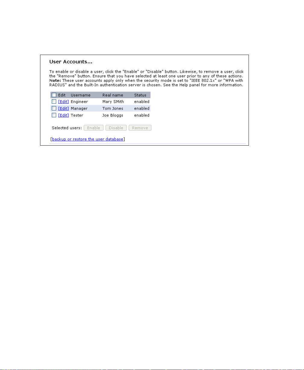
Chapter 7: Managing User Accounts
Enabling And Disabling User Accounts
an existing user account, first click the checkbox next to the username so that the
box is checked.
Then, choose an action such Edit, Enable, Disable, or Remove.
7.2.4 Enabling And Disabling User Accounts
A user account must be enabled for the user to log on as a client and use the
access point.
You can Enable or Disable any user account. With this feature, you can maintain a
set of user accounts and authorize or prevent users from accessing the network
without having to remove or re-create accounts. This can come in handy in situations where users have an occasional need to access the network. For example,
contractors who do work for your company on an intermittent but regular basis
might need network access for 3 months at a time, then be off for 3 months, and
back on for another assignment. You can enable and disable these user accounts as
needed, and control access as appropriate.
7.2.5 Enabling A User Account
To enable a user account, click the checkbox next to the username and click Enable.
A user with an account that is enabled can log on to the wireless access points in
your network as a client.
Psion Teklogix 9160 G2 Wireless Gateway User Manual
74

Chapter 7: Managing User Accounts
Disabling A User Account
7.2.6 Disabling A User Account
To disable a user account, click the checkbox next to the username and
click Disable.
A user with an account that is disabled cannot log on to the wireless access points in
your network as a client. However, the user remains in the database and can be
enabled later as needed.
7.2.7 Removing A User Account
To remove a user account, click the checkbox next to the username and
click Remove.
If you think you might want to add this user back in at a later date, you might consider disabling the user rather than removing the account altogether.
7.3 Backing Up And Restoring A User Database
You can save a copy of the current set of user accounts to a backup configuration
file. The backup file can be used at a later date to restore the user accounts on the AP
to the previously saved configuration.
7.3.1 Backing Up The User Database
To create a backup copy of the user accounts for this access point:
1. Click the [backup or restore the user database] link.
A File Download or Open dialog is displayed.
2. Choose the Save option on this first dialog.
This brings up a file browser.
Use the file browser to navigate to the directory where you want to save
the file, and click OK to save the file.
You can keep the default file name (
file, but be sure to save the file with a
wirelessUsers.ubk
.ubk
extension.
) or rename the backup
7.3.2 Restoring A User Database From A Backup File
To restore a user database from a backup file:
Psion Teklogix 9160 G2 Wireless Gateway User Manual 75

Chapter 7: Managing User Accounts
Restoring A User Database From A Backup File
1. Select the backup configuration file you want to use, either by typing
the full path and file name in the Restore field or click Browse and
select the file.
(Only those files that were created with the User Database Backup func-
.ubk
tion and saved as
Restore; for example,
backup configuration files are valid to use with
wirelessUsers.ubk
2. Click the Restore button.
When the backup restore process is complete, a message is shown to indi-
cate that the user database has been successfully restored. (This process is
not time-consuming; the restore should complete almost immediately.)
Click the User Management tab to see the restored user accounts.
.)
Psion Teklogix 9160 G2 Wireless Gateway User Manual
76

CHANNEL MANAGEMENT 8
8.1 Navigating To Channel Management.....................79
8.2 Understanding Channel Management.....................79
8.2.1 How It Works In A Nutshell ....................80
8.2.2 For The Curious: More About Overlapping Channels . . . . . . . 80
8.2.3 Example: A Network Before And After Channel Management . . 80
8.3 Configuring And Viewing Channel Management Settings..........81
8.3.1 Stopping/Starting Automatic Channel Assignment . . . . . . . . . 82
8.3.2 Viewing Current Channel Assignments And Setting Locks . . . . 83
8.3.3 Viewing Last Proposed Set Of Changes . . . . . . . . . . . . . . 83
8.3.4 Configuring Advanced Settings (Customizing And Scheduling
Channel Plans) ...........................84
Psion Teklogix 9160 G2 Wireless Gateway User Manual 77

 Loading...