

zapco ST-4X DSP, ST-6X DSP Quick Start Manual

ST-X DSP Series
Quick Start Guide
Congratulations on the purchase of your new Zapco ST-X DSP series product.
Please go to www.zapco.com to download the PC Control Program. You will also find the User’s Manual on the web
site for download. Also, please check back periodically for any new updates to programs. If you are experienced
with DSP and you want to jump right into the installation and tuning, we provide this Fast-Start sheet to give you the
basic info you need to get up and running right away.
ST-X DSP - Physical Connections
1 12 23 34 45 56 6
7
8
1. The amplifier RCA connectors. The 2 extra RCA outputs on each amplifier provide a fully processed output to
drive an external amplifier such as a subwoofer amp.
2. High Level inputs are provided for OEM installation to a factory installed stereo system.
3. Auto turn on can be engaged to provide current-sensing turn on from factory speaker wires.
4. The PC USB connects to your PC with the USB cable provided with your amplifier for DSP control.
5. The Comm Port is provided for future expansion (i.e. the optional HD Bluetooth Module).
6. LEDs indicate power on and protect, and also indicate when the USB is communicating with your PC.
7. A Toslink connection is provided for an auxiliary digital input (ST-6X DSP only).
8. Ground: The ground must be connected to the frame or to a solid metal body part that has a direct connection
to the frame A inputs. The Remote terminal can be connected to the +12 trigger output of the head unit to turn on
the amplifier. The +12V Bat power terminal must be connected directly to the positive (+) terminal of the vehicles
battery.
9. On-board fuses (ST-4X DSP only). If they ever blow, they must be replaced with identically rated fuses.
10. Speaker output connectors for channels 1~4 (ST-4X DSP) and 1~6 (ST-6X DSP).
When bridging the left and right channels of the amplifier, you use the left channel (Ch1) positive and the right
channel (Ch2) negative, as indicated on the chassis by the speaker terminals.
89 10
10
The ST-X DSP Series Control Program
he control program (GUI) for the ST-X DSP amplifiers is the same functionally for both the 4-Ch ST-4X DSP and the
T
6-Ch ST-6X DSP except for the number of channels. Both will have a default system in the channel designation column
but since you have complete control over all functions, you can use all channels as they best suit your individual
system. Download the GUI (Graphic User Interface) from www.zapco.com > downloads, if you have not already done
that, and load the GUI from the .exe file. Connecting the PC: Connect the PC to the ST-X DSP amp using the supplied
SB cable. NOTE: The ST-X DSP GUI is very forgiving about PC Screen resolution. However the ideal resolution 1600 x
U
900 optimal on most PC’s.
1
2 3
4
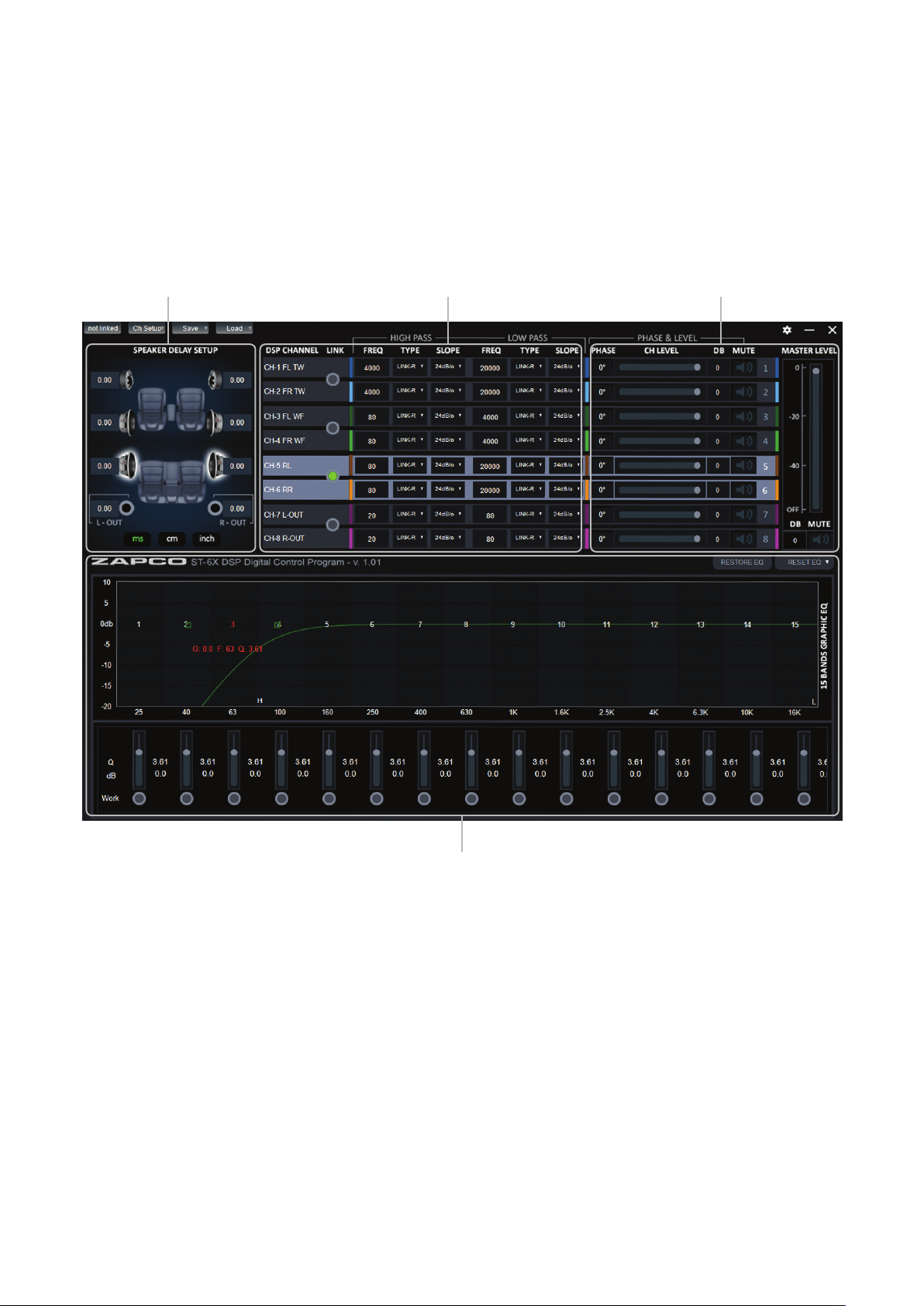
At the very top of the Screen you will find the Navigation bar. Channel Setup is where you will tell the program what inputs
and outputs you are using. To begin you need to define your system (see the full manual for complete instructions).
1. At the left of the main GUI Screen is the Delay section. Since you can not sit directly in the center of the car, the
program can delay the arrival time of near speakers so it will sound as though you are right in the middle of the car.
2. The next section holds the Channel Selection and Crossover. You can pick channels on at a time or you can pick
them by pair. Each channel has a High Pass (HP) and a Low Pass (LP) filter. You can choose the Shape of the crossover
from Butterworth, Linkwitz-Riley, or Bessel and the Slope using the drop-down menus.
3. Phase/Level: The next section is for adjusting levels and checking Polarity to be sure all speakers are in phase with
each other. The MUTE buttons allow you to turn off any speakers that you do not want to hear while you are tuning
other speakers. You will also find a master level control here and a system MUTE button.
4. The lower section of the GUI is devoted to equalization. Here are 15 bands of parametric equalization for each
output channel and you can vary Frequency, Gain, and Q (the shape of the adjustment) for each band in several ways.
Frequency: Each band is numbered. You can simply click onto a band button and drag it to where you want it. When
you click onto a band there is a “Heads-up display” of the frequency, gain, and Q of the band. Any band that has been
adjusted from 0dB is highlighted by the green dot under the band’s slider.
To aid the tuning process you can temporarily bypass a channels equalization. You can also the reset function to reset
one channel or to reset all channel to default positions with no equalization.
 Loading...