


i-Force

Contents
Mission Statement....................................................................2
Warnings
Wire Size
...................................................................................
....................................................................................
Installation Guidelines............................................................. 6
i-FORCE Inputs
Bass Boost Control
.................................................................
................................................................
10
i-FORCE............................................................................11
..........................................................................................
i-250
i-2100
........................................................................................
11
14
i-450..........................................................................................17
i-4100
i-5100
........................................................................................
........................................................................................
20
23
4
5
9
i-600..........................................................................................26
i-1200
Speaker Wiring
........................................................................................
.......................................................................
29
32
Speaker Impedance Table..................................................... 34
System Diagrams
Technical Assistance
...................................................................
.............................................................
1
35
42

Mission Statement
ZAPCO IS DEDICATED TO THE PURSUIT OF AUDIO FIDELITY.
Our passion, our “Driving Force” is to design and manufacture car audio
products of unsurpassed quality, to provide unparalleled support and service
for these products and to conduct business in a manner that will enhance
the quality of life for all involved. There is absolutely no substitute for
experience; that is a simple fact of life. Another simple fact is that for over 30
years, ZAPCO has been the leader in defining quality standards for the car
audio industry. These years of experience have led to a thorough
understanding of the challenges that are unique to the world of car audio.
ZAPCO’s relentless quest for sonic purity consistently yields imaginative
designs that utilize the most innovative technologies. The resulting products
set the criteria by which all others in the industry are judged. Feel the
passion, hear the quality, know the performance and reliability by making
ZAPCO the “Driving Force” in your car audio system.
2

The Quest
For over 30 years, Zapco has been building a reputation that is the
envy of the industry. It is a reputation for sound quality, engineering integrity,
and p roduct reliability. This reputation has spread throughout the world. And
now, wherever you find audio equipment, the p erson who wants the best in
12-volt audio products knows that Zapco is the only name you need.
In today’s market, however, price often becomes as important as
any other quality. There are a variety of o p tions competing for your aftermarket dollar. Today’s consumer must balance audio, performance
accessories, and appearance accessories in their automotive budget. We at
Zapco have been searching for several years to find a product that we could
bring to this more price conscious market segment.
We have now found it.
The challenge for Zapco was to bring the market a bulletproof
product that sounds on par with the industry’s better amps at a price that we
knew today’s import/performance minded market would demand. We
worked closely with one of Asia’s most respected manufacturers to develop
a p roduct that would meet our sound quality and production quality
standards at a price today’s consumers could appreciate.
i-FORCE!
A quick look at the following pages will show that we have certainly
succeeded. These products proudly wear the Zapco brand, and will deliver
the world famous Zapco reliability. To compliment the Zapco performance,
we have assured that i-Force provides all the features today’s consumer
wants and needs. Every i-Force amp provides variable electronic high/low
crossovers, RCA and speaker level inputs, auxiliary outputs and variable
remote b ass control. For maximum convenience, i-Force controls are
accessed right from the top of the amp, under the removable Zapco badge.
And all this value is loaded into a package that will excite the most
style conscious of buyers. The chassis of i-Force was designed to fit with
today’s modern import styles and to fit naturally into a customized interior
installation. And the bold i-Force styling underscores our intent to make the
i-Force amps perform with a “take no prisoners” attitude.
Style, Performance, Value…i-Force
3

Warnings
Zapco highly recommends that a fuse or circuit breaker be placed
within 18" of the battery. Although products have adequate internal
protection, it is possible that a pinched power wire between the component
and the battery may result in a fire. The protection device should be placed
where it can be accessed easily and all wiring should be routed safely and
correctly according to the following guidelines:
Do not run wiring close to hot or spinning objects.
Always use wire grommets when routing wire through the firewall or
any other metal panels.
Make sure that the potential for pinched wiring is avoided by routing
all wires away from moving hinges and seats. This a lso includes brake, gas
and clutch pedals, hood and trunk hinges, etc.
Caution:
Continuous exposure to excessive sound pressure levels may cause
permanent hearing loss. Zapco strongly advises that you use common
sense when setting volume levels. If you experience ringing in the ears, it
could cause permanent hearing damage!
CAUTION!
When connecting our amplifiers to pre-wired stock speakers, care
must be taken that there are no common connections in the speaker wires,
i.e. minus to minus or plus to plus connections, as this will cause the
amplifier to go into immediate protection or may cause damage to the
amplifier. Output connections are not common chassis ground. Please
follow the hookup instructions in this owner’s manual. Any questions should
be directed to your local Zapco dealer or call us at 209-577-4268.
4

Wire Size
Most people understand the importance of a clean signal source for
good sou n d reproduction. But, what about your 12 volt power source? It’s
often surprising how many people (even professional car sound people) will
obsess about signal wire but routinely provide the amp only a fraction of the
current it needs to do its job. The most common wire gauge used in car
audio is 10-gauge. The most common location for amplifiers is in the trunk.
Take a look at the chart below. If you want to have any respectable
amount of power for your amp, you need an 8-guage wire to the trunk as a
bare minimum. If you want enough power to drive woofers, your going to
need at least a 4-gauge wire to the rear.
Length of Run
0- 4 - 7 - 10 - 13 - 16 - 19 - 22 -
Current Demand
0 - 20 amps 14 12 12 10 10 8 8 8
20-35amps 12108866 6 4
35-50amps 1088664 4 4
50-60amps 886444 4 2
65-85amps 664422 2 0
85-105amps 66422220
105-125amps 44422000
125-150amps 22220000
4 Ft 7 Ft 10 Ft 13 Ft 16 Ft 19 Ft 22 Ft 28 Ft
Lets just look at a fairly small system. If you use an i-Force 250 (25
amps) for the highs and an i-Force 2100 (40 amps) for the woofers, you
need at least a 4-gauge wire to provide 65 amps at the trunk. Anything less
and your car won’t go boom. It’ll just go Blap!
It takes lots of current to make lots of power!
And remember! An electrical circuit is just that…a circuit. For current
to travel, you must complete the circuit from the positive terminal to the
negative terminal. Whatever you use for power (B+) you must also use for
Ground (B-). 4-gauge power…4-gauge ground!
So! Use this chart! Add up your fuses and c hoose your wire to
match the total maximum current draw. And always use the same gauge for
the main ground as you do for main power.
5

Installation Guidelines
Mounting your i-Force Amplifier is easy. Keep in mind the following
guidelines:
•
The a mplifier may be mounted in any direction, on wood, metal or
carpet.
•
The metal case of the amplifier may be grounded or left isolated.
• The amplifier requires adequate ventilation. Position the amplifier with
sufficient surrounding area for proper cooling.
• Keep top and vents clear for proper internal cooling.
• Keep the amplifier out of the engine compartment and other locations
that may cause excessive heat or moisture.
• Do not mount the amplifier to a subwoofer enclosure or any other
place that may have excessive vibration!
6
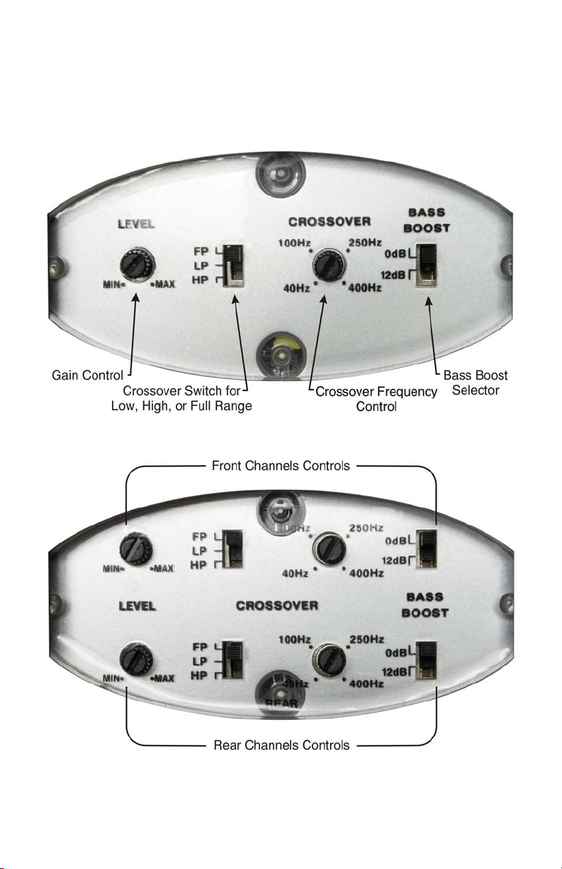
i-FORCE Controls
Remove the Zapco name badge in the center of your i-Force
amplifier to reveal the system controls. Below are the layouts for the 2
channel an d 4 channel and Mono i-Force amps.
2 Channel Controls
4 Channel Controls
7
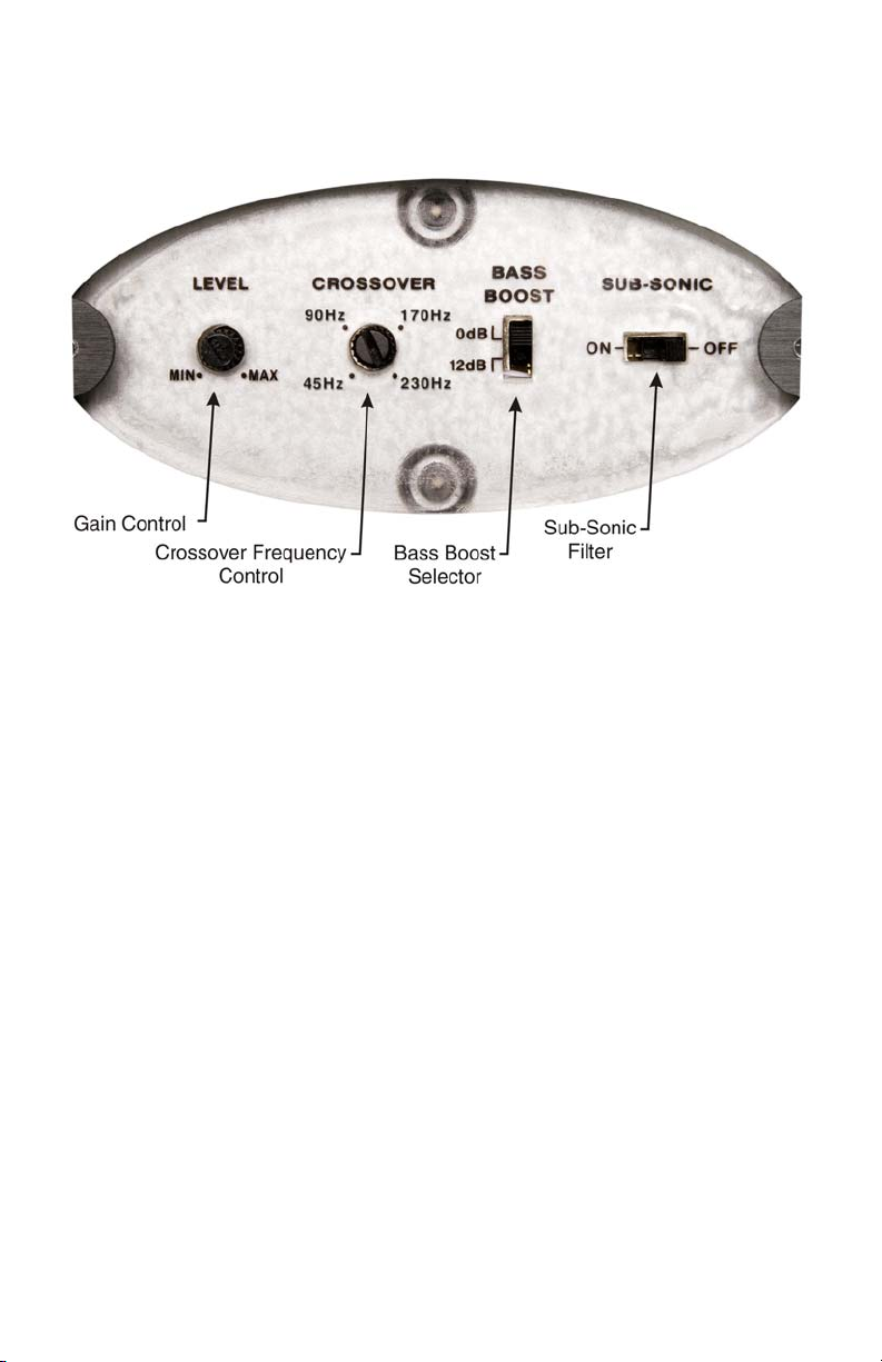
Mono Controls
8
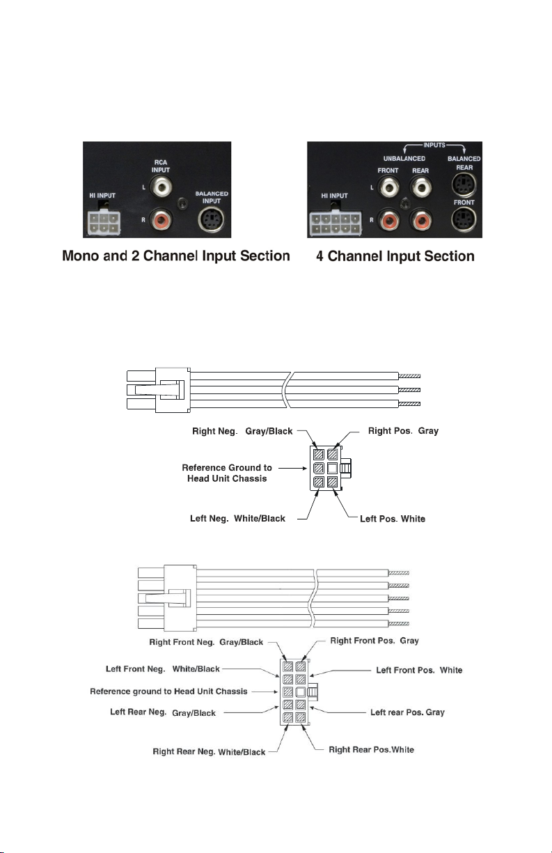
i-FORCE Inputs
To provide maximum versatility, i-Force amplifiers provide both RCA
and SymbiLink™ inputs. They also provide Balanced High Level inputs that
can hook directly to your speaker outputs of your factory system.
Below are the wire codes for the Balanced High Level input plugs.
Warning: The black reference ground wire must be hooked up to the
head unit’s chassis ground or performance will be seriously degraded!
Mono and 2 Channel Input Plug
4 Channel Input Plug
9
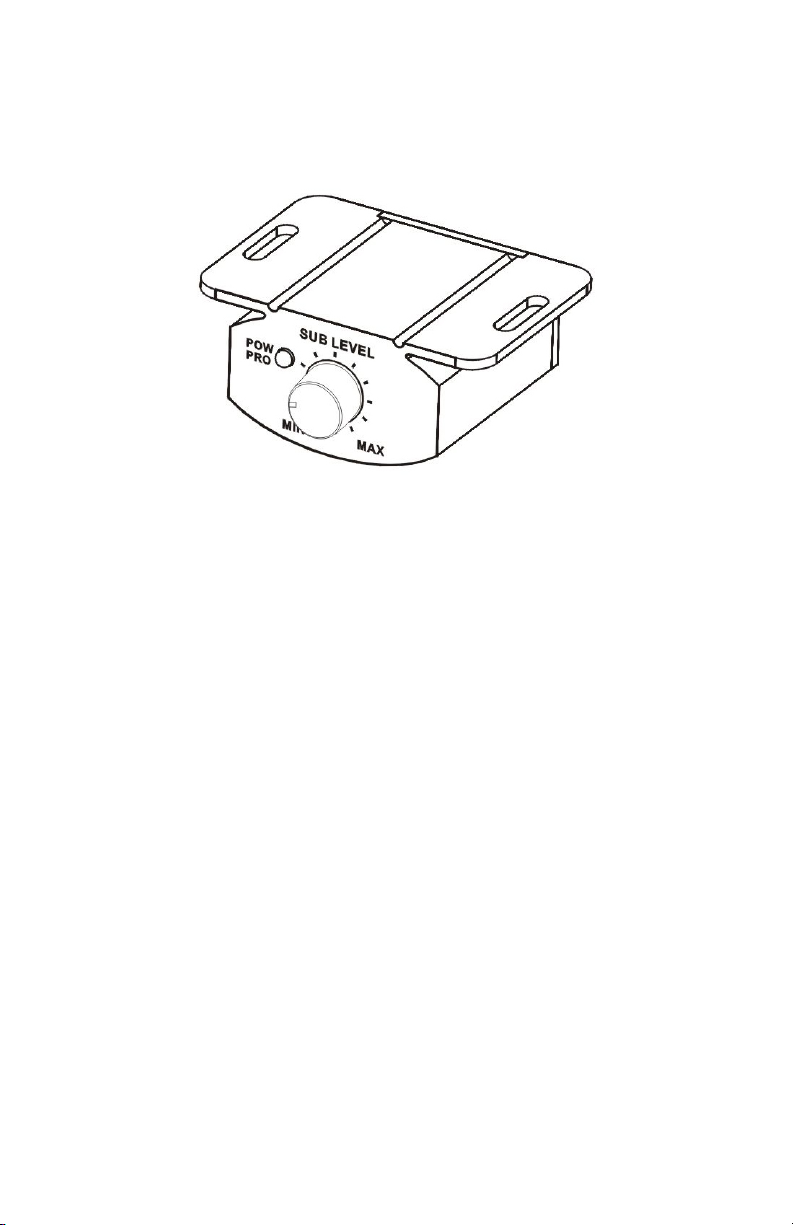
Bass Boost Control
To provide more of the control you want with your system, we have
developed a unique wired remote gain control for i-FORCE amplifiers.
The i-Force remote is included with every i-Force amplifier and is
activated whenever the crossover is switched to low pass mode. The upper
limit of volume, for the remote, is controlled by the gain control on the amp
itself.
To set up for bass control, simply turn the remote fully clockwise, set
the amp gain for the maximum you want the bass volume to be, then turn
down the remote. You can now use the remote as your primary bass control.
10
i-FORCE
i-250
• 300 watts Total Music Power
•
•
• Remote Level Control with Wired Remote
• Top Mount System Controls for Easy Access.
• Highly Efficient Compact Design for Easy Mounting
• Switchable Bass Boost Circuit
•
2 Channel Stereo Amplifier / Bridgeable / 3 Channel Capable
RCA Inputs, SymbiLink™ inputs, or Speaker Level Inputs
Variable Crossover
11
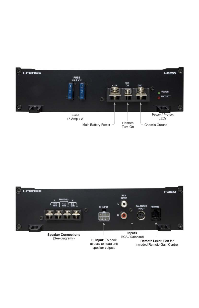
i-250 Hookup
Power End
Signal End
12

i-250 Specifications
Output Power Rating
Stereo Output 4 ohm @ 14.4V (0.05%) 2 x 75W
Stereo Output 2 ohm @ 14.4V (0.05%) 2 x 125W
Bridged Output 4 ohm @ 14.4V (0.05%) 1 x 250W
Channel separation (Full Rated Power) > 50dB
THD Distortion with 22k Filter 0.10%
Frequency Response (-3dB) 10 - 25KHz
S/N Ratio (A-Weighted) > 90dB
Input Gain Control
Low L evel Input 150mV — 4V
High Level Input 450mV — 12V
Input Impedance
Features
Battery Voltage Range for Operating 10.5V — 16V
LED Indicator Red/Green
Protection (Short, Thermal, Overcurrent) Yes
Crossover HP/FULL/LP
Variable Hi-Low Pass 40Hz — 400Hz
Crossover Slope 12dB/Octave
Bass EQ at FULL/LP at 45Hz 12dB
Dimensions mm / in.
Length 194mm / 7.625 in.
Width 273mm / 10.75 in.
Height 57mm / 2.25 in.
Power
20kΩ
13
 Loading...