

Page 1

Owner's manual
DC-series
Sound Quality / Integration Amplifiers
With Full On-Board Processing and Zapco DPN
Before operating the unit, please read this manual throughly
and retain it for future reference.
Page 2
Protect your Investment
Note your information below for reference:
Model # Serial #
Date Purchased
And: Register your Zapco product now
At: www.zapco.com
Page 3

Mission Statement
ZAPCO IS DEDICATED TO THE PURSUIT OF AUDIO FIDELITY.
Our passion, our “Driving Force” is to design and manufacture car audio products of
unsurpassed quality,to provide unparalleled support and service for these products and
to conduct business in a manner thatwill enhance the quality of life for all involved.
There is absolutely no substitute for experience; that is asimple fact of life. Another simple
fact is that for over 30 years, ZAPCO has been the leader in definingquality standards for
the car audio industry. These years of experience have led to a thoroughunderstanding
of the challenges that are unique to the world of car audio. ZAPCO’s relentless quest for
sonic purity consistently yields imaginative designs that utilize the most innovative
technologies. Theresulting products set the criteria by which all others in the industry
are judged. Feel the passion, hear thequality, know the performance and reliability by
making ZAPCO the “Driving Force” in your car audiosystem.
Sonic Purity
Our dedication to sonic purity requires that the highest quality internal components are
used.
Resistors
All resistors (other than power resistors) are 1% precision low noise metal film.
This is a key reason why ZAPCO products have the industries’ best low noise specifications,
and why you won’t see as much fluctuation in our test certificates as you will with other
brands. Precision resistors also reduce distortion and improve channel matching.
Capacitors
Capacitors are similar to batteries. Like a battery, they store energy and have
electrolyte (internal fluid). Also like a battery, a capacitor can have a very limited life.
“Computer grade” capacitors for example, are reliable only in cool environments with
very little current applied to them. Only the best high current and high temperature
capacitors should be used in an auto-sound application. Although these capacitors
typically cost five times as much as those commonly used in other brands, ZAPCO insists
that no audio degradation will occur over time.
Transistors
Two types of transistors are used in ZAPCO products, bipolar and MOSFET.
MOSFET transistors are rugged, high current output devices that are best suited as
switches. They are the choice for switching power supplies. They are however, very
non-linear and are not suitable for use as audio outputs. They cannot be matched and
their inherent distortion requires too much feedback to achieve reasonable distortion
levels. Bipolar output transistors are used exclusively in the audio stage of all DC
Series amplifiers. The audio performance of a bipolar transistor heavily outweighs any
minor advantages a MOSFET might offer regarding durability. We solve the durability
concerns by simply using more output devices than the amplifier requires. This gives us
a bulletproof amp with the sound quality we demand of a ZAPCO product.
-3 -
Page 4

Welcome to the World of Zapco Digital - 2012
For 2012: Zapco takes you to the next level with the new Zapco DC-Series amps, with
more control more features and speaker level inputs the make integration of the DC amps
with a factory stereo a breeze
What's New for 2012
First, of course, the DSP-Z8 has 2 more output channels than its predecessor. This allows
an active 4-way system to be set up, or an active 3-way main system with a rear fill.
The crossover of the DSP-Z8 has been improved by allowing up to 36dB/Octave slopes for
a sharper cut-off and better speaker protection.
The Signal delay function of the DSP-Z8 has more resolution, allowing adjustments down
to 3mm
Direct Muting has been added and can be used by individual channels or by channel pairs
The new DSP-Z8 accepts speaker level inputs through its balanced RCA input connectors.
You can just attach RCA connectors directly to the speaker outputs of a factory stereo
(up to 22 Volts) and plug them right into the DSP-Z8.
A voltage sensitive EQ filter lets you activate an EQ filter at a predetermined input level
to compensate for active factory equalization when integrating the processor and/or
amplifiers into your factory stereo system.
In this manual we will take you through the programming and control functions of the
Zapco DSP-Z8 and the on-board DSP in the Zapco DC Series of DSP controlled amplifiers
as well as the networking operations of Zapco's DPN system.
-4 -
Page 5

Transformers
Most of the transformers used in our products are hand-wound to ensure
maximum quality. This provides a guarantee that current capability, efficiency, and
radiated noise are all kept within our demanding parameters. Another critical aspect of
the transformer is mounting; all transformers are securely mounted in their respective
chassis. Transformers are massive, and if not securely mounted can cause failure among
internal components due to vibration.
Power Supplies
Regulated or Unregulated? For years amplifier designers have debated which
type of power supply is best. What's the truth about power supplies? They each have
advantages and disadvantages and there is no, one, best type. Limiting yourself to one
type of power supply limits your amplifier design flexibility. ZAPCO uses both types of
power supplies depending on the intended use of each amplifier, as well as expected
current demands and operating environment.
Zapco Digital
Who has the number one name in state of the art audio equipment?
Zapco!
But, when most people think of Zapco, they picture compact, powerful, great sounding
amplifiers. While this picture is true enough, it misses one big piece of the Zapco legend.
Signal Processing!
Zapco virtually created the concept of high sound quality processing in the late 70's
when we created the PEQ. This was a high voltage preamp/EQ with and audiophile input
stage and 9 bands of equalization for each channel. It brought a whole new level of
performance to car sound. In the 90's the name was changed to SEQ and the unit was still
in production until 2006. We still refurbish them to this day.
In the 80's we took processing to another new level with the PX. This was the first
audiophile quality preamp EQ with a multi-order crossover. In addition, all four EQ bands
were parametric, so now you could customize the EQ parameters to you car. The result:
By the late 80's even non-Zapco dealers had to have a source of PX's for all their
competition cars.
The next leap was in the 90's, when Zapco introduced the SX, (later to become the
SX-SL). This unit expanded the Parametric EQ to 5 bands, added dual high pass and three
way band pass crossovers, added variable crossover slopes, bass-to-highs balance, and
SymbiLink™ Balanced inputs.
In 2004 Zapco Introduced the DSP-6, stand-alone, PC controlled Digital Signal
Processor. We also introduced the DC Reference line of Amplifiers. These were the first
ever PC controlled amplifiers with on-board DSP's for each and every channel. The DC
Reference amps were controlled by the revolutionary Zapco DPN control network that
allowed a single PC screen to control each amplifier in the system separately and to
apply memory settings globally to the network.
-5 -
Page 6

Welcome to the World of Zapco Digital - 2012
For 2012: Zapco takes you to the next level with the new Zapco DC-Series amps, with
more control more features and speaker level inputs the make integration of the DC amps
with a factory stereo a breeze
What's New for 2012
First, of course, the DSP-Z8 has 2 more output channels than its predecessor. This allows
an active 4-way system to be set up, or an active 3-way main system with a rear fill.
The crossover of the DSP-Z8 has been improved by allowing up to 36dB/Octave slopes
for a sharper cut-off and better speaker protection.
The Signal Delay function of the DSP-Z8 has more resolution, allowing adjustments down
to 3mm
Direct Muting has been added and can be used by individual channels or by channel pairs
The new DSP-Z8 accepts speaker level inputs through its balanced RCA input connectors.
You can just attach RCA connectors directly to the speaker outputs of a factory stereo
(up to 22 Volts) and plug them right into the DSP-Z8.
A voltage sensitive EQ filter lets you activate an EQ filter at a predetermined input level
to compensate for active factory equalization when integrating the processor and/or
amplifiers into your factory stereo system.
In this manual we will take you through the programming and control functions of the
Zapco DSP-Z8 and the on-board DSP in the Zapco DC Series of DSP controlled amplifiers
as well networking operations of Zapco's DPN system.
-6 -
Page 7
Addressing Components on the DPN
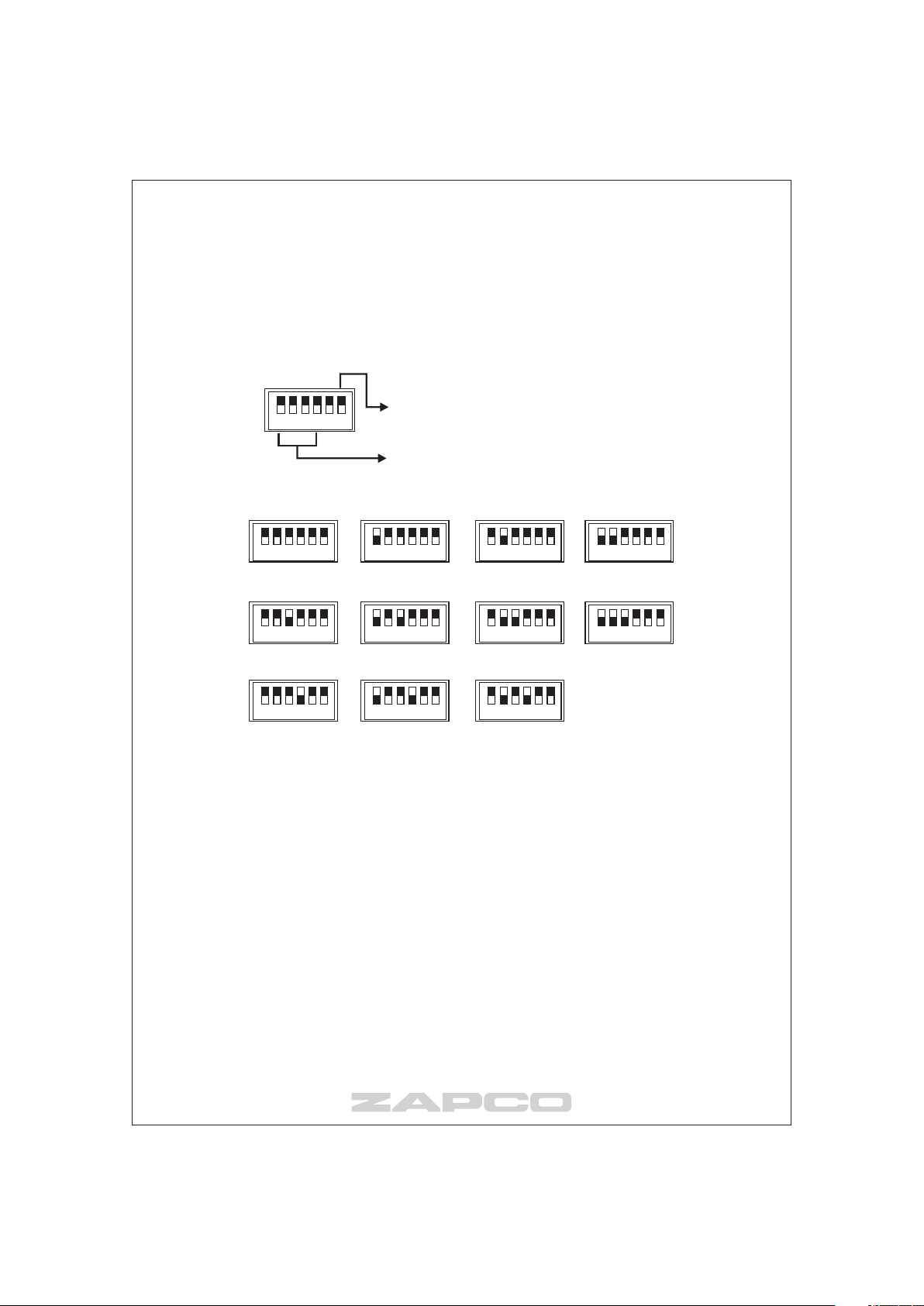
The Digital Programming Network consists of 10 amplifier/DSP nodes numbered 0
through 9.
NOTE: Turn all amps off before setting address switches
Sw6 is not used, nor is Sw5
1
ON
65432
i
Sw1 to Sw4 are engaged to address the
network node of each device.
Settings for Each Node
1
ON
65432
1
ON
65432 1
ON
65432 1
ON
65432
10 2 3
1
ON
65432 1
ON
65432 1
ON
65432 1
ON
65432
5 6 74
1
ON
65432 1
ON
65432 1
ON
65432
9 108
Up to 10 devices can be addressed using the DIP switch. Only the first 4 pins are for
addressing the devices. Pin 5 is not used, and pin 6 is not used.
-7 -
Page 8
The Zapco Digital Programming Network
All Zapco DC series amplifiers, and the ZAPCO DSP-Z8, stand-alone Digital Signal
Processor incorporate Zapco’s exclusive Digital Programming Network™ (DPN).
This network allows the user to program all amp functions using a PC
The amps DSP can then be programmed to control Gain, Volume, Crossover,
Equalization, and even Time Delay. More importantly, the system allows you to network
all amps in your system so you can control up to 10 amplifiers from a single PC
window.
To allow higher resolution graphics and to make the setting go much faster, we
have developed a program that lets you make all adjustments with a PC.
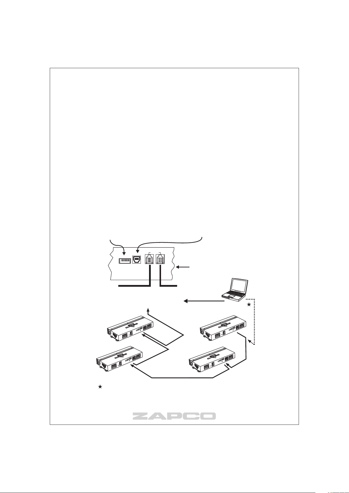
Each Digital Control product has a USB interface. This allows you to plug a PC into any
unit on the network and control the entire network.
USB input allows a PC to be hooked
The amp’s DIP Switch allows you to
address each amplifier to it’s own location
on the network. Then when you call up the
amp for programming, it will even identify
itself by its location and its model number.
directly to the amp with a standard
USB cable. The Z8-R also has a
USB port so the PC can be plugged
in at the dash, without disturbing the
installation.
ADDRESS
1 2 3 4 5 6
PC CONTROL
ON
I/O DATA
Both I/O Data ports are bi-directional.
One connects to the control direction,
while the other connects to the next
amp in the network.
To Control
Optional Zapco Z8-R in-Dash Remote
The PC can be be plugged into the network at any device on the network. It can also be
plugged into the USB recepticle of the Z8-R remote if that is being used.
NOTE: The Z8-R is designed for use primarilly for the DSP-Z8. It will not network. It will
only affect the amp it is attached to, so it does not provide global settings.
To Next Amplifer
-8 -
PC
Page 9
Since the programming of the DSP-Z8 and the DC Series amplifiers are the same we will
begin with the DSP-Z8 and how the programming works.
Then we will review the DC Series amplifiers.
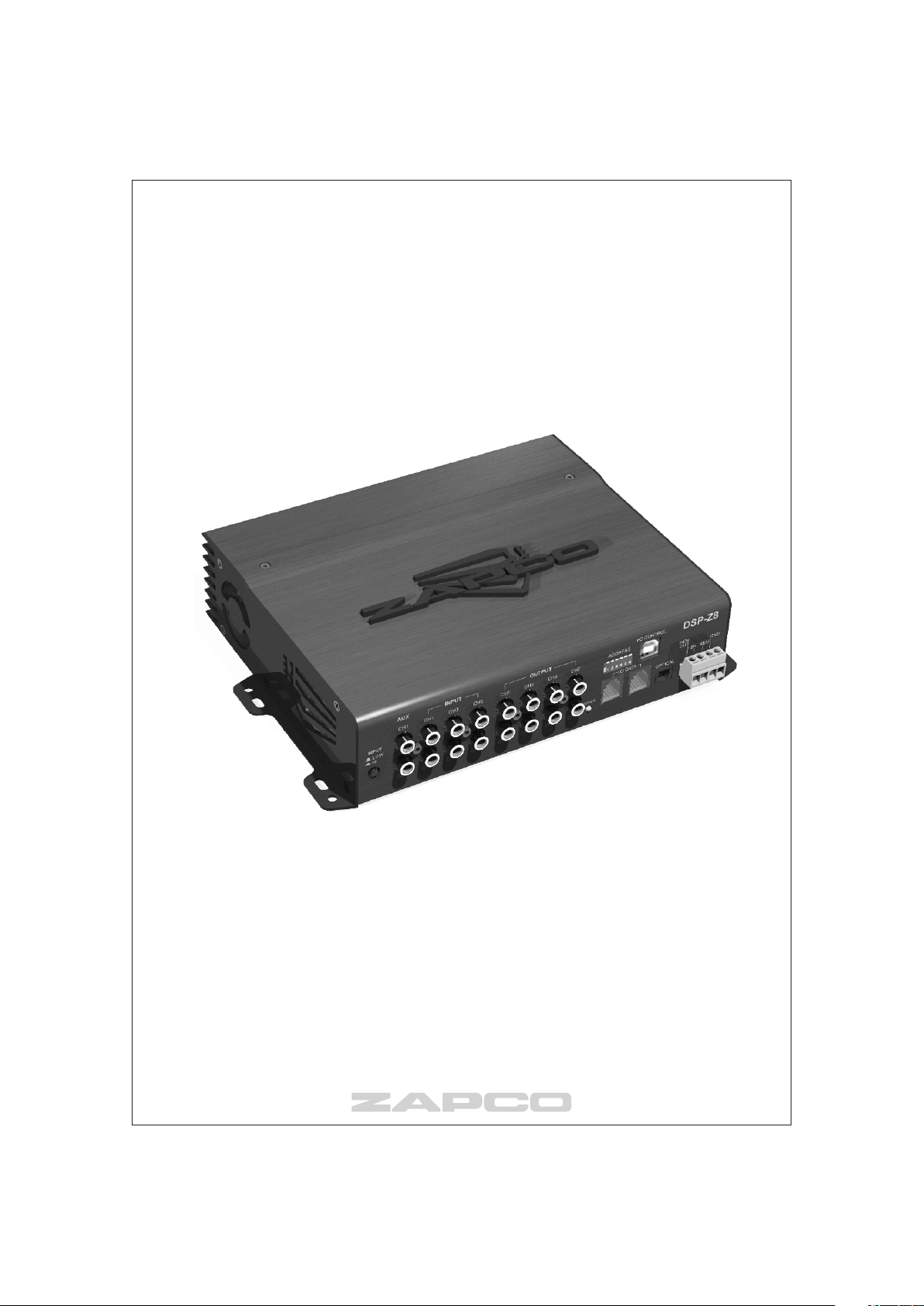
DSP-Z8 : Six In / Eight Out Channel Digital Signal Processor
Specifications
THD:
Analog < 0.0015 Digital < 0.0008 Sensitivity 0.5V to 22V
S/N Ratio:
Digital > 100dB Analog > 99dB Control Input Mini USB
Dimensions 220mm(L) x 55mm(H) x 180mm(W)
-9 -
Page 10
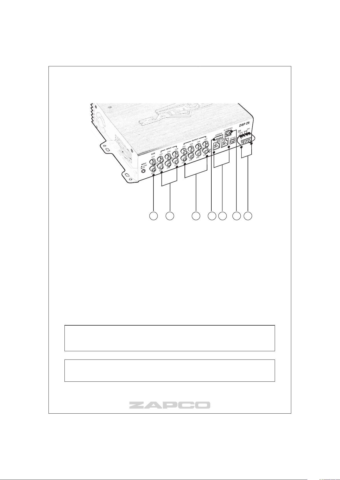
DSP-Z8 Connection Panel
5 1 2 3 6 4 7
Front Panel Connections
1) RCA Inputs- Six channels of input are available through RCA connectors*.
2) RCA Outputs-4 sets of RCA Connectors provide eight channels of output.
3) DIP Switch-Six position DIP switch is used to address the unit and assign a
node on the Zapco Digital Programming Network.
4) USB Port- Like all Zapco DC products, the DSP-Z8 has a USB port to interface
with a PC for all DSP programming functions.
5) Auxiliary Input
Digital Input- Optical connector for SPDIF input
Analog- RCA connector for analog Aux-in
6) Data Connectors- Two RG connectors provide Data in/out for network cables
(and Z8-R control input)
7) Power Connector- Provides Power, Ground, Turn On, and Aux +12 volt out **
* Note: To use speaker level inputs from a factory stereo, simply attach RCA
connectors to the factory speaker wires(up to a 22v signal). Assure that the DSP or
amplifier is in High Level input mode and plug the speaker wires directly into the RCA
inputs.
** Note: The Zapco DC Series also has DC-offset sensing for automatic turn-on. If
you use speaker level inputs from a factory stereo the DC product will turn on
automatically and also provide +12v trigger output to turn on other components.
-1 0-
Page 11

Zapco Digital – Functions and Control
The Zapco DSP-Z8 is a stand-alone eight channel Digital Signal Processor. It has all
the DSP functions of the Reference Digital amps, but, as a stand-alone piece, it brings
the world of Zapco Digital to any amplifier.
The RCA inputs allow you to use the DSP-Z8 with any after market head unit, and
two auxiliary inputs allow an extra input by either RCA or SPDIF Digital. The DSP-Z8 and
all Zapco DC Series amplifiers will also accept balanced speaker level signals from a
factory amplified system to add high-end sound to factory stereos.
The Zapco Digital functions include Input Sensitivity, Output Gain, Crossover,
Equalization, and Time Delay. Each Reference Digital piece also has an Input Commutator
that allows any input to be assigned to any output. The Commutator also allows input
pairs to be summed for a 2-channel mono input to any output channel. In addition, you
can combine input channels together to sum their signals for integrating actively crossed
over signals to a single full range signal. All DSP functions may be applied to each channel
independently or they may be applied in stereo pairs.
Control : Zapco provides two options options for control of the Zapco Digital products.
Processing control:Load the program included with your digital product into a PC and
program all functions directly from the programming screen. You will find all functions on
a single, easy to use, screen.
The other Zapco Digital control option is the Z8-R remote. The Z8-R is a small in-dash
control designed primarilly for the DSP-Z8. The Z8-R provides Volume up/down, Memory
selection and Input selectioin so the you will have a volume control for a full gain digital
input. While it will work as remote volume and memory select for a DC amplifier it will only
on the amp it is plugged directly into.
The PC Program
A program disk was included with your Digital Reference Amplifier. The program will work
on any Windows OS from 95 forward. The installation is fast and straightforward and will
auto-load right from the disk.
-1 1-
Page 12

Zapco Digital Control Screen
1
2
3
4
5
7
The PC Programming Screen
The PC programming screen has 5 sections. They are (top to bottom) Channel Select,
Function/Graph, Equalizer, Crossover, and Input/Delay. We will consider these sections
individually and we think you will find the controls very user friendly.
There are numerous drop-down menus at the arrow points in the DSP screen. You can
use the drop-down arrows to make choices, or simply highlight the box you want to
change and type in your choice manually. Most small boxes are switches and are switched
by placing the mouse over them and clicking you will also find that you can click into most
adjustments and use your scroll wheel to change the values.
For example: If you click the slider of a EQ level, your scroll wheel will move the level
1dB per scroll step, you can also click on the slider and "drag" it or you can highlight the
value and type in a new value. Choose the method you find most convenient.
6
9
-1 2-
Page 13

1) Channel Select The top section of the PC screen allows you to determine which
available channels you will be programming. The number of options will be determined
by the Zapco Digital item you are programming. The Zapco Digital Control will identify
which unit you are programming and how many channels are available. You can adjust
the channels individually, or in stereo pairs as required. Simply move the mouse to your
choice and click it on.
2) Function/Graph In this section you can turn the processing functions on or off to
compare the sound of your modified response to the unprocessed sound by clicking the
buttons on of off with your mouse. You can also monitor the graph to see, in real time,
how your adjustments will affect the input signal.
3) Equalizer In this section you can make the adjustments to the parametric equalizer.
The top row sets the level of boost or cut at the center frequency, up to±15dB
The next row sets the Q (shape) of the equalization. A low Q affects a wide range
of frequencies while a high Q affects a narrow range of frequencies. The Graph screen
will let you see how the different Qs affect your response.
The bottom row of the EQ screen sets the center frequencies. The EQ section is
a true parametric EQ. We have set factory defaults at about ½ octave intervals. However
you can alter the center frequencies to fit the requirements of your car.
4) Mute The Mute buttons allow you to temporarily turn off some of the active channels.
This is very handy in tuning when you want to hear the response of an individual channel.
5) Crossover For each channel, when you have turned on the crossover function, you
can choose to run a High pass, a Low pass, or a Band pass crossover. You can also choose
a crossover slope of 6dB,12dB, 24dB, or 36dB per octave. from the drop-down menu,
and you can choose to use a Butterworth or a Linkwitz-Riley filter.
6) Voltage Sensitive EQ Allows you to set one parametric EQ filter for each channel
or channel pair that will come on only then the system reaches a pre determined volume.
This is most often used in factory integration when the factory system rolls off the bass
frequencies to protect the factory woofer.
See more under Getting Started later in this manual
7) Input This lower section of the screen contains the Input Commutator, Source
Selector and Phase control
Channel At the top of the screen you picked the channel you would adjust. Here
you can pick which channel you will use as input for the chosen channel. In this way you
can assign the same channel pair as input to all channels of multi-channel amps.
NOTE: Ch5+6 (as above) means you will "sum" the two channels to a single mono input.
Ch5/6 means you will use channels 5 and 6 as a stereo input pair.
Also: The Input Channel selector gives you the option of summing 2 or 3 stereo pair into
one single stereo pair for OEM integration. This lets you combine highs, mids, and lows
from a factory system into a single stereo output and eliminate the factory crossover.
Sensitivity: After picking the inputs for your channels, you can set the channel's
sensitivity for maximum signal with minimum noise.
Selector: This control is only on the DSP-Z8. It allows you to choose from the Main
input, the Analog Aux-in, or the Digital SPDIF input
-1 3-
Page 14

8) Output After the sensitivity has been set at optimum for all channels you can control
the maximum system volume with the Main output control and balance the channels by
attenuating the output of the louder channels to bring all channels into correct acoustic
balance with the individual channel output levels..
9) Signal Delay: Time delay allows you to adjust the arrival time of each speaker's
output by delaying the closer speakers. This will improve the sound stage and provide
superior imaging and balance. With the Zapco Digital pieces this is an easy operation.
1) Measure the distance from your head (at your listening position) to each
speaker in millimeters or inches.
2) Note the distance of the farthest speaker.
3) Add to each speaker the inches need to equal the furthest speaker, and
note how many inches are needed for each.
4) Now just dial in the delay to match the added inches for each speaker
and your delay is set.
Program Upgrades
The Zapco Digital Programming Network is an evolving entity. As it evolves we can issue
program updates.
If there are firmware upgrades we will issue a new hex code which you can place on your
desktop. The upgrade process is straightforward.
o Note the COM port your program is using then close the program
o Open the Zapco Updater (on the disk) and:
set the COM port to match what the system is using
Browse to the new HEX file and click it into the Zapco Updater
o Turn the system off and back on and the system will update.
o When updating is finished, close the updater, and your done.
-1 4-
Page 15

Yes, please read this manual thoroughly. We wrote it to help ensure that you get
the most from your investment in your Zapco amplifier. If you find, after reading
the manual, that you still have questions please feel free to give us a call at
1(800)47-FORCE, or, drop us a note at
Power and Wire Gauge
The wire you use for the power and ground connections of your amplifier are
absolutely critical. The plain simple fact is that it takes power to deliver power. If
you do not provide the proper amount of 12V power to your amplifier, you will
never reach the full power potential of your amp. Take a look at the chart below.
If you want to have any respectable amount of power for your amp, you need an
4-gauge wire to the trunk as a bare minimum. If you are running any Zapco ZXseries amp in you trunk you need at least an 0 gauge wire.
Read, Use, and Enjoy
www.zapco.com
Recommended Wire Gauge
Up to
20 A
35 A
50 A
60 A
85 A
105 A
125 A
150 A
You can certainly save money by buying cheap small gauge wire, but
remember...It will cost you in power and may even damage your car by passing
too much current and causing shorts or even fires. Protect your investment in
Zapco amplifiers by using high quality, proper gauge wire.
And remember... Current in the amplifier runs in a complete circuit from the
battery to the amp and back to the battery through the chassis and frame. The
ground wire us just as important as the power input wire. Positive and Negative
connections must always use the same gauge wire.
Installation Guidelines
Mounting your Reference Amplifier is easy. Keep in mind the following
guidelines:
The amplifier may be mounted in any direction, on wood, metal or carpet.
The metal case of the amplifier may be grounded or left isolated.
The amplifier requires adequate ventilation. Position the amplifier with
sufficient surrounding area for proper cooling. Keep fan and vent
endplates clear for proper internal cooling.
4 Ft
14
12
10
8
4
4
4
2
7 Ft
12
10
8
8
4
4
4
2
10 Ft
12
8
8
4
4
4
4
2
13 Ft
10
8
4
4
4
2
2
2
-1 5-
16 Ft
10
4
4
4
2
2
2
0
19 Ft
8
4
4
4
2
2
0
0
22 Ft
8
4
4
4
2
2
0
0
28 Ft
8
4
4
2
0
0
0
0
Page 16

Keep the amplifier out of the engine compartment and other locations that
may cause excessive heat or moisture.
Make sure your ground point is at the frame or a chassis point with direct
frame contact. Note: the "quiet metal" on many new cars make body
panels very bad ground points, so always try to use the frame.
Do not mount the amplifier to a subwoofer enclosure or any other place
that may have excessive vibration!
Gain Setting
Matching Your Components for Best Sound
Proper gain setting is one of the most important factors in setting up a stereo
system. At the same time, gain setting is most often done wrong. Turning up the
gain of an amp is the very last thing you should ever do to a system.
An amplifier is a step up transformer. Period. Any signal you put in is boosted by a
fixed factor. Music, hiss, or any other noise, it doesn’t matter. A large number of
noise problems are simply a matter of improper gain settings. The goal of gain
setting is to achieve the maximum amount of musical output from the amplifier
while getting the least amount of hiss or noise from the system. Your Z-Series
Series amplifier accepts an extremely wide range of input levels. As little as . 5
volts on the RCAs to as much as 8 volts. The basic gain setting is very simple and
requires no special tools. Whether you have a simple system with a deck and an
amp, or a system with a deck, line driver, equalizer, crossover, and amp, the
procedure is always the same. First, hook up the system with all gain controls at
minimum (turn the gain pot fully counter-clockwise with a small screwdriver).
Then turn on the head unit and turn up the volume. If you achieve clean sound,
and, more volume than you want, you don’t need to make any adjustments.
However, if you turn up the volume and begin to hear distorted sound before it
becomes loud, you are clipping (distorting) the deck (probably a little over ¾
volume). Turn the deck down just enough to hear clean sound again, and then
move to the next component in your system. With the deck playing at “maximum
clean volume” adjust the gain of the next component to its “maximum clean
volume”. If you adjust your gains this way, always starting at the head unit and
working down the line to the amplifier, you will get the most performance out of
your amplifier(s) with the least amount of unwanted distortion and noise.
Presenting
The Zapco DC-Series
Sound Quality / Integration Amplifiers
-1 6-
Page 17

FEATURES
DC-352 / DC-752 2-Channel Amps
On-board, full function DSP
Bridgeable
Intelligent rail voltage control
Stable into 4 ohms bridged or 2 ohms stereo load
USB input for PC control
Signal input RCA connectors
Optional digital programming network
Ducted flow cooling
Heavy-Duty, high-current, insulated terminal blocks
Space saving flush wiring connections
Three-channel capable
Gate drive boost circuit
High-current biolar outputs
Optically isolated MOSFET power supply
Quality ZAPCO construction
DC-364 / DC-1004 4-Channel Amps
On-board, full function DSP
Bridgeable
Intelligent rail voltage control
Stable into 4 ohms bridged or 2 ohms stereo load
USB input for PC control
Signal input RCA connectors
Optional digital programming network
Ducted flow cooling
Heavy-Duty, high-current, insulated terminal blocks
Space saving flush wiring connections
Tree-channel capable
Gate drive boost circuit
High-current biolar outputs
Optically isolated MOSFET power supply
Quality ZAPCO construction
DC-501 / DC-1101 Full Range Mono Amps
On-board, full function DSP
Intelligent rail voltage control
Stable into 2 ohms
USB input for PC control
Signal input RCA connectors
Optional digital programming network
Ducted flow cooling
ZAPCO EHVC output circuitry
Heavy-Duty, high-current, insulated terminal blocks
Space saving flush wiring connections
Gate drive boost circuit
High-current biolar outputs
Optically isolated MOSFET power supply
Quality ZAPCO construction
-1 7-
Page 18

FEATURES
DC-656 6-Channel Amp
On-board, full function DSP
Bridgeable
Intelligent rail voltage control
Stable into 4 ohms bridged or 2 ohms stereo load
USB input for PC control
Signal input RCA connectors
Optional digital programming network
Ducted flow cooling
Heavy-Duty, high-current, insulated terminal blocks
Space saving flush wiring connections
Tree-channel capable
Gate drive boost circuit
High-current biolar outputs
Optically isolated MOSFET power supply
Quality ZAPCO construction
ZAPCO DIGITAL PROGRAMMING NETWORK
The amp’s DIP Switch allows you to
address each amplifier to its own location
on the network. Then when you call up the
amp for programming, it will even identify
itself by its location and its model number
Both I/O Data ports are bi-directional.
One connects to the control direction,
while the other connects to the next
amp in the network.
PC CONTROL
ADDRESS
1 2 3 4 5 6
ON
USB input allows a PC to be
hooked directly to the amp with a
standard Mini USB cable. The
DRC-SL also has a USB port so the
PC can be plugged in at the dash,
without disturbing the installation.
I/O DATA
To Next Amplifier
To Control
-1 8-
Page 19

DC-352 / DC-752
CONNECTION
INPUT
CH2
INPUT
LOW
HI
CH1
HI / LOW
switch
HEAD UNIT
DC-364 / DC-1004
INPUT
CH2 CH4
INPUT
LOW
HI
CH1
INPUT
CH3
ADDRESS
1 2 3 4 5 6
ON
PC CONTROL
INPUT
INPUT
CLIP
CLIP
I/O DATA
LOW-Z
LOW-Z
HI
HI
LOW
LOW
PROTECT
PROTECT
POWER
POWER
LOW Z indicator
LOW Z switch
Input clip indicator
ZAPCO digital programming network ports
See page 3
ADDRESS
1 2 3 4 5 6
ON
PC CONTROL
INPUT
CLIP
I/O DATA
LOW-Z
HI
LOW
PROTECT
POWER
LOW Z indicator
LOW Z switch
HI / LOW
switch
ZAPCO digital programming network ports
Input clip indicator
See page 3
HEAD UNIT
This amplifier has a signal input terminal of RCA connector type for low level inputs.
Adjustment of input levels is accomplished by the gain control of both channels.
Adjusting this control allows the amplifier gain to be controlled to match and balance both channels.
The RCA input connector should be used when connecting the radio/cassette line out and this connection
is usually made using RCA-RCA connector wires.
-1 9-
Page 20

DC-501 / DC-1101
CONNECTION
DC-656
INPUT
LOW
HI
INPUT
INPUT
LOW
HI
HI / LOW
switch
CH2
CH1
ADDRESS
1 2 3 4 5 6
ON
ZAPCO digital programming network ports
See page 3
HEAD UNIT
INPUT
CH2 CH4 CH6
CH1
INPUT
CH3
PC CONTROL
INPUT
CLIP
Input clip indicator
INPUT
CH5
I/O DATA
LOW-Z
LOW Z switch
PC CONTROL
ADDRESS
1 2 3 4 5 6
ON
POWER
HI
PROTECT
LOW
LOW Z indicator
I/O DATA
INPUT
CLIP
LOW-Z
HI
LOW
PROTECT
POWER
LOW Z indicator
LOW Z switch
Input clip indicator
ZAPCO digital programming network ports
See page 3
HEAD UNIT
This amplifier has a signal input terminal of RCA connector type for low level inputs.
Adjustment of input levels is accomplished by the gain control of both channels.
Adjusting this control allows the amplifier gain to be controlled to match and balance both channels.
The RCA input connector should be used when connecting the radio/cassette line out and this connection
is usually made using RCA-RCA connector wires.
-2 0-
Page 21

POWER CONNECTION
DC-352/DC-752/DC-364/DC-1004/DC-501/DC-1101/DC-656
FUSE
GROUND
+12V Power
Connect the +12V terminal of the amplifier to the + terminal of the battery using the same diameters
the ground cable,
making sure you install in-line fuse holder, approximately 300 or 400 mm.
From the + terminal of battery, making sure that there is no fuse in the battery holder.
GROUND
Disconnect the battery and connect the GND (ground) terminal to the cars chassis.
Keep this cable as short as possible (not longer than 500 mm. or less).
Making sure that the connection with the chassis is rust free and clear of paint or grime.
REMOTE
Connect the REM terminal of the amplifier to the power antenna terminal in the car ignition switch
using 12 or 16 ga. electrical wire.
BATTERY
+12V TURN ON GND
to REMOTE Turn-on
from HEAD UNIT
GROUND
HEAD UNIT
Caution
First make the grou nd connection, the n +12V wire con nection, and finally the remote
connection. Furthermore, t he +12V wire must always be fus ed at the battery for protection
against possible damage. nIf you need to replace the p ower fuse, replace it with a fuse of
the same value. It may result in a seri ous hazard to u se a fuse of a different type or rating.
-2 1-
Page 22

DC-352 / DC-752
1 Channel Bridged
BRIDGE
CH1 CH2
CH1
CLIP
2 Channel Stereo
BRIDGE
CH1 CH2
SPEAKER CONNECTION
CH2
CLIP
Speaker Impedance
CH1 SUB
or FULL RANGE
4~8 ohms
CH1
CLIP
3 Channel Tri Mode
BRIDGE
CH1 CH2
CH1
CLIP
CH2
CLIP
CH2
Speaker Impedance
2~8 ohms
CH1
CH2
CH2
CLIP
Speaker Impedance
4~8 ohms
CH1
CH3-MONO
SUBWOOFER
-2 2-
Speaker Impedance
4~8 ohms
Page 23

DC-364 / DC-1004
2 Channel Bridged
BRIDGE
CH1 CH2
CH1
CLIP
4 Channel Stereo
CH2
CLIP
SPEAKER CONNECTION
BRIDGE
CH3 CH4
CH3
CLIP
CH4
CLIP
Speaker Impedance
4~8 ohms
CH2
CH1 SUB
or FULL RANGE
CH2 SUB
or FULL RANGE
BRIDGE
CH1 CH2
CH1
CLIP
6 Channel Tri Mode
BRIDGE
CH1 CH2
CH1
CLIP
BRIDGE
CH3 CH4
CH1
Speaker Impedance
CH2
CH3
CLIP
CLIP
CH4
CLIP
2~8 ohms
CH3
CH4
CH5-MONO
SUBWOOFER
CH2
BRIDGE
CH3 CH4
CH1
Speaker Impedance
CH2
CH3
CLIP
CLIP
CH4
CLIP
CH3
4~8 ohms
CH6-MONO
SUBWOOFER
CH4
-2 3-
Page 24

SPEAKER CONNECTION
DC-501 / DC-1101
SPEAKER
CLIP
-2 4-
MONO
SUBWOOFER
Page 25

SPEAKER CONNECTION
DC-656
3 Channel Mode
BRIDGE
CH1 CH2
CH1
CLIP
5 Channel Stereo
BRIDGE
CH1 CH2
CH1
CLIP
CH2
CH3
CLIP
CLIP
CH2
CH3
CLIP
CLIP
BRIDGE
CH3 CH4
BRIDGE
CH3 CH4
Speaker Impedance
4~8 ohms
BRIDGE
CH5 CH6
CH5
CH4
CLIP
CLIP
CH6
CLIP
Full-Range
SUBWOOFER
Full-Range
BRIDGE
CH5 CH6
CH5
CH4
CLIP
CLIP
CH6
CLIP
SUBWOOFER
Speaker Impedance
-2 5-
CH4
4~8 ohms
CH3
Speaker Impedance
2~8 ohms
CH2
CH1
Page 26

DC-656
6 Channel Mode
BRIDGE
CH1 CH2
SPEAKER CONNECTION
BRIDGE
CH3 CH4
BRIDGE
CH5 CH6
CH1
CLIP
CH2
CH3
CLIP
CLIP
CH5
CH4
CLIP
CLIP
CH6
CLIP
CH6
Speaker Impedance
2~8 ohms
CH5
CH4
Speaker Impedance
2~8 ohms
CH3
CH2
Speaker Impedance
2~8 ohms
CH1
-2 6-
Page 27

SPECIFICATIONS
Rated power output
-RMS power, 4 ohms stereo -------
-RMS power, 2 ohms stereo -------
-RMS power, 8 ohms bridged ------
-RMS power, 4 ohms bridged ------
Signal to Noise Ratio ------------------
Frequency Response ------------------
THD@RMS Watts ----------------------
Slew rate ------------------------------
Channel Separation -------------------
Damping factor -----------------------
Fuse Rating ----------------------------
Input Sensitivity ----------------------
Dimensions (mm) ---------------------
DC-352
100W x 2CH
200W x 2CH
-
418W x 1CH
>96dB
20Hz ~ 20KHz (+/-0.25dB)
0.06%
>29 V/µS
66dB
>800@4
15A x 3
500mV~10V (+/- 5%)
400(L) x 55(H) x 180(W)
DC-364
50W x 4CH
90W x 4CH
-
180W x 2CH
>95dB
20Hz ~ 20KHz (+/-0.12dB)
0.01%
>23 V/µS
55dB(front) / 58dB(rear)
>500@4
15A x 3
500mV~10V (+/- 5%)
480(L) x 55(H) x 180(W)
DC-752
200W x 2CH
370W x 2CH
-
780W x 1CH
>90dB
20Hz ~ 20KHz (+/-0.5dB)
0.05%
>40 V/µS
60dB
>1000@4
30A x 3
560mV~10V (+/- 5%)
600(L) x 55(H) x 180(W)
DC-1004
150W x 4CH
250W x 4CH
500W x 2CH
-
>95dB
20Hz ~ 20KHz (+/-0.5dB)
0.03%
>36 V/µS
60dB
>800@4
30A x 3
500mV~10V (+/- 5%)
600(L) x 55(H) x 180(W)
The above specifications shall be modified by manufacturer for improvement without prior notice.
-2 7-
Page 28

SPECIFICATIONS
Rated power output
DC-501
-RMS power, 4 ohms mono -------
-RMS power, 2 ohms momo -------
Signal to Noise Ratio ------------------
Frequency Response ------------------
THD@RMS Watts ----------------------
Slew rate ------------------------------
Damping factor -----------------------
Fuse Rating ---------------------------
Input Sensitivity ----------------------
Dimensions (mm) ---------------------
Rated power output
-RMS power, 4 ohms stereo ---------------------------------------
-RMS power, 2 ohms stereo ---------------------------------------
Signal to Noise Ratio --------------------------------------------------
Frequency Response --------------------------------------------------
THD@RMS Watts ------------------------------------------------------
Channel Separation ---------------------------------------------------
Slew rate ---------------------------------------------------------------
Damping factor --------------------------------------------------------
Fuse Rating ------------------------------------------------------------
Input Sensitivity -------------------------------------------------------
Dimensions (mm) -----------------------------------------------------
350W x 1CH
500W x 1CH
>85dB
20Hz ~ 20KHz (+/-0.5dB)
0.013%
>25 V/µS
>600@4
20A x 3
500mV~10V (+/- 5%)
340(L) x 55(H) x 180(W)
DC-1101
800W x 1CH
1200W x 1CH
>95dB
20Hz ~ 20KHz (+/-0.5dB)
0.03%
>40 V/µS
>800@4
30A x 3
500mV~10V (+/- 5%)
600(L) x 55(H) x 180(W)
DC-656
50W x 4CH + 100W x 2
90W x 4CH + 180W x 2
>95dB
20Hz ~ 20KHz (+/-0.5dB)
0.02%
>23 V/µS
60dB
>160@4
40A x 3
500mV~10V (+/- 5%)
620(L) x 60(H) x 200(W)
The above specifications shall be modified by manufacturer for improvement without prior notice.
-2 8-
Page 29

TROUBLE SHOOTING GUIDE
This power amplifier has protection features to prevent most forms of damage.
If the unit senses excessive heat, short circuited speakers or overload, the protection indicators will
be lit and the system will be turned off. Prior to checking the wiring for any fault, you should turn all
level controls down and turn off power. If the amplifier shuts down due to excessive heat, the
protection indicators will not be lit: simply allow the amplifier to cool down.
Before removing your amplifier, refer to the list below and follow the suggested procedures.
Always test the speakers and their wires first.
AMPLIFIER IS NOT POWERED UP
Check if at least +12V DC is present on the battery power terminal.
Check if at least +13.8V DC is present on the remote terminal.
Check if a good ground connection is present. Check all fuses.
Check if the protection LED is not lit.
PROTECTION LED ILLUMINATES WHEN AMPLIFIER IS POWERED UP
Check to see if any speaker wires are short-circuited to the chassis or themselves.
Remove speaker wires and reset the amplifier. If the protection LED still comes on,
then the amplifier is at fault.
FUSE BLOWING
Check if the minimum speaker impedance is met.
Check for short-circuits on power cable and vehicle chassis.
OVERHEATING
Check if the minimum speaker impedance is met.
Check speakers for short-circuits.
Check if there is good airflow around the amplifier.
SOUND TOO LOW-DISTORTED SOUND
Check if the input level control is set to match the output level of the source unit.
Check the head unit's volume.
Check speakers for short-circuits.
Check if crossover frequencies have been properly set.
HIGH HISSING NOISE - ENGINE NOISE IN SPEAKERS
Check if a good ground connection is present. Most engine noises are caused by
grounding issues.
Hissing noise is most often caused by gain issues. Proper gain matching is
usually required to eliminate hissing noise.
-2 9-
Page 30

Technical Assistance
Should you experience a problem with your DSP6-SL or DRC-SL, please contact the
dealer that sold you this product. If your dealer is unable to solve your problem, you
may contact the factory service department directly.
Phone: (209) 577-4268 Monday - Friday, 8AM - 5PM Pacific Standard Time FAX: (209)
577-8548
Also, check our web page, www.zapco.com, for tips. You can also e-mail for technical
help directly from our web page.
If you need to return this product for repair, please call the factory for a Return Materials
Authorization (RMA) number. We will ask you for information that will include your name,
return shipping address, daytime phone number, model and serial number, and a detailed
description of your problem. A photocopy of your original purchase receipt is necessary
to determine warranty status and should also be included. Once we issue you an RMA,
please write it in a highly visible area on the package. ZAPCO will not accept any
packages that do not have a valid RMA number clearly marked on the outside of the
package.
Once you have a valid RMA number, send all repairs to:
A.R.P.A. of America Corp. / Zapco
Attn.: Service Department
3037 E Palm Ave Suite 102, Manteca, CA 95337
-3 0-
Page 31

NOTES
-3 1-
Page 32

ARPA of America Corporation
3037 E Palm Ave Suite 102
Manteca, CA 95337
Phone: (800) 47-Force
The Zapco DC-Series is a joint venture of ARPA of America
and ARPA Italy and manufactured in Korea
 Loading...