

Zanussi ZW5531GL, ZX5531GL, ZW5540GLT User Manual

INSTRUCTIONS FOR USE
Tipolitografia Montagnani - Cod. 534777 402
NOTICE D' EMPLOI
GB FR
Getting to know your new cooker
Thank you for choosing one of our products.
Our cookers are of simple, rational design. They are constructed to the best
standards to ensure good service and outstanding safety.
Please read this manual carefully; it will provide all the advice needed to allow
you to obtain the best results from the very first day.
These instructions for use are divided into two sections:
1st section: for the qualified technician.
2nd section: for the user.
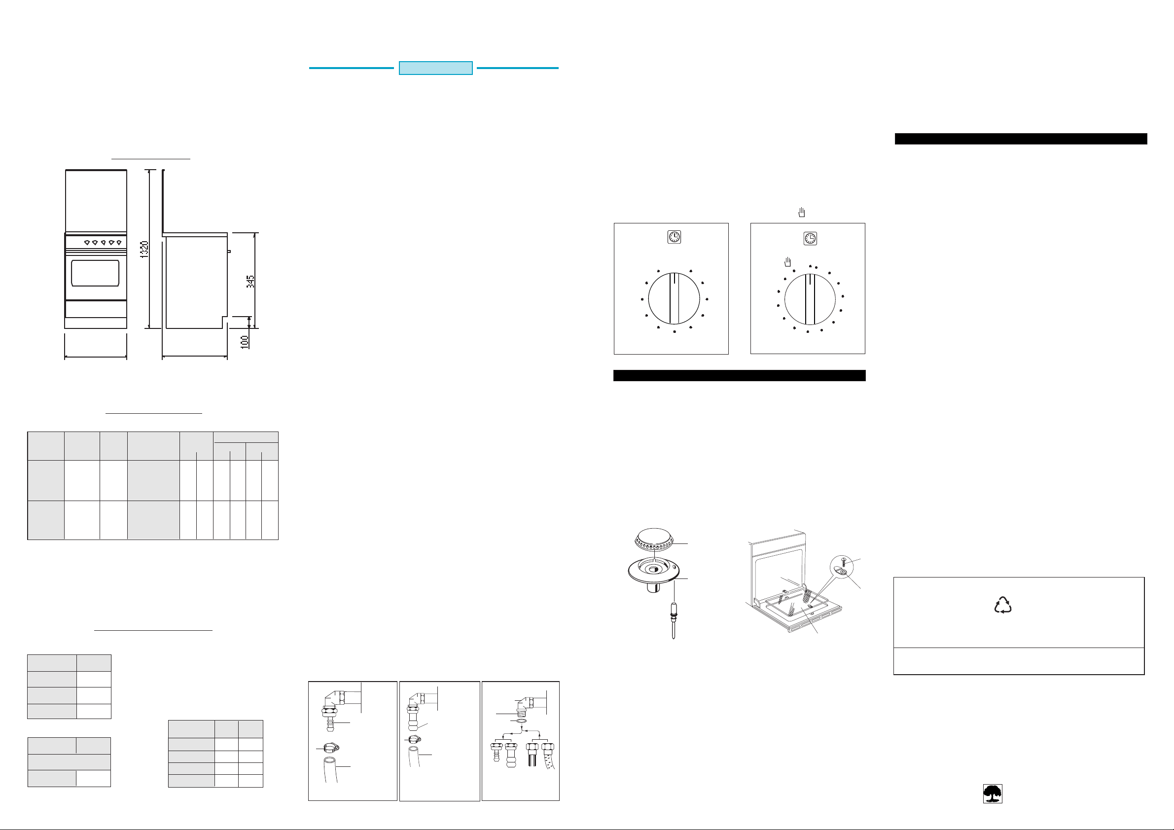
Fig. 1
OVERALL DIMENSIONS
MODEL WIDTH (X)
51 480
52 495
1ST SECTION
FOR THE QUALIFIED TECHNICIAN
INSTALLATION
IMPORTANT: The gas and electricity connections and any adjustments must
be made by skilled staff. The manufacturer refuses all liability
for damage of any kind resulting from failure to comply with
current regulations or negligent installation of the appliance.
1) INSTALLING THE COOKER
After removing the external packaging and the internal packaging of the various
moving parts, position the cooker ensuring that the installation area is normally
ventilated without any drafts which might blow out the burners. To ensure
perfect presentation, the stainless steel parts are mounted on the appliance
protected by a plastic covering, which must be removed before using the
appliance.
N.B.: The sides of adjoing kitchen units in contact with the cooker must be capable
of withstanding temperatures of approximately 90°C. It is essential that
Particularités
Utilisation de la minuterie (fig. 27) selon les modèles
Certaines cuisinières sont équipées d'une minuterie, réglable de 1 à 60 minutes,
qui indique la fin de cuisson par un signal sonore. Pour actionner cette minuterie,
tourner la manette (fig. 27) sur la droite jusqu'au temps désiré. Pour des temps
court (inférieurs à 15 minutes), tourner la manette en dépassant le temps initialement
choisi et revenir en arrière pour garantir une plus grande précision du réglage.
Utilisation du programmateur de fin de cuisson (fig. 28)
Selon les modèles
Certaines cuisinières sont équipées d'un programmateur de fin de cuisson, réglable
de 0 à 120 minutes qui permet l'arrêt automatique du four ou du grilloir.
Pour actionner ce programmateur, tourner la manette (fig. 28) dans le sens des
aiguilles d'une montre jusqu'au temps désiré. Mettre en fonctionnement le four
ou le grilloir.
Une fois le temps sélectionné écoulé, le four ou le grilloir s'arrêteront
automatiquement. Si vous ne désirez pas programmer un temps, vous pouvez
utiliser la position manuelle de ce programmateur en tournant la manette dans le
sens inverse des aiguilles d'une montre jusqu'à la position .
furniture in contact with the cooker are heat resistant or protected by a similar
material. If the adjacent cabinet top is higher than the cooker hob, a 20 mm,
clearance should be kept between the furniture unless lined with a suitable
fireproof material the clearance above the cooker hot should be at least of
X 500
630 mm.
GAS APPLIANCES
This appliance is not connected to a device to vent the combustion products. It
must therefore be installed and connected in conformity with the installation
standards in force. Particular attention must be paid to the standards on ventilation
of the room.
1a) VENTILATION OF ROOMS
Remember that this appliance can be installed and work in well-ventilated rooms
only, according to the standards in force, such as to allow , with openings on the
external walls or with special ducts, a correct natural or forced ventilation ensuring
50
45
40
Fig. 27 Fig. 28
0
55
5
10
12
11
15
10
20
35
25
30
90
0
stop
10
20
30
40
50
80
60
70
permanently and sufficiently both the entry of the air needed for correct combustion
CHART 1
GAS TYPE
NATURAL
GAS
BUTANE GAS
L.P.G. GAS
PROPANE GAS
OPERATING
PRESSURE
mbar
20
28
30
37
TECHNICAL DATA: GAS PART
NOZZLE
Ø
Nº
135
FAST
95
SEMI-FAST
130
OVEN THERMOSTA T
135
OVEN THERMOMETER
105
GRILL
85
FAST
62
SEMI-FAST
80
OVEN THERMOSTA T
85
OVEN THERMOMETER
70
GRILL
BURNER
DESIGNATION
POWER
kW
Max. Min.
3,09
0,62
1,56
0,32
3,00
3,00
1,90
3,09
0,62
1,56
0,32
3,00
3,00
1,90
FLOW RATE
l/h g/h
Max Min. Max Min.
295
59
149
30
286
286
181
225
114
219
219
138
43
23
and the removal of spent air. In particular when there is only this gas appliance
in the room, there must be a hood over the appliance to ensure the natural and
direct removal of spent air, with a vertical straight duct of length equal to at least
twice the diameter and a minimum section of at least 100 cm2. For the indispensable
entry of fresh air into the room there must be a similar 100 cm2 (5,16 cm2 x kW)
opening directly to theoutside, situated at a height near floor level so that it is not
blocked either inside or outside the wall and so as not to cause disturbances to
correct burners combustion and to the regular removal of spent air and with a
difference of height with respect to the outlet opening of at least 180 cm. Remember
that the quantity of air necessary for combustion must never be less than 2m3/h
for each kW of power (see total power in kW on the appliance data plate).
In all other cases, i.e. when there are other gas appliances in the same room, or
when natural direct ventilation is not possible and natural indirect or forced
ventilation must be installed, contact a qualified specialist who will install and make
the ventilation system, scrupulously observing the regulations contained in the
standards in force. The openings must be so positioned that there are no draughts
of air which cannot be tolerated by the occupants.
2) GAS CONNECTIONS
The installation must be in accordance with regulations set by the local gas Authority.
This appliance belongs to class "1" against fire dangers (see N.B.). Between the
cooker and gas supply line is required a gas shut off valve (easy of access) to be
Avant toute opération de nettoyage, débrancher la prise de courant ou couper
l'alimentation électrique de l'appareil. Fermer également le robinet d'alimentation
du gaz.
Un entretien fréquent vous facilitera les opérations de nettoyage décrites ci-après.
Corps de la cuisinière
Utiliser une éponge humectée d'eau tiède et de détersif liquide non corrosif. Rincer
et essuyer soigneusement.
Brûleurs - Grilles
Les différentes parties du brûleur (fig. 29), le support (B) et la tête de brûleur (A)
peuvent être nettoyés en les faisant tremper dans une solution d'eau chaude et de
détersif liquide non corrosif; Après le trempage, bien les rincer et les essuyer
soigneusement. Lors du remontage, veiller à ce que soit tout bien positionné.
NETTOYAGE
A
V
kept closed when the cooker is not in use. The pressure regulators for Lpg must
Values for town gas injectors are valid for extra european country only.
be in accordance with the requirements.
2a) CONNECTION TO GAS CYLINDER
B
F
Cooker working with Lpg gas can be connected with a flexible pipe (T ø 8 mm)
fixed to inlet connector A (fig. 2). The pipe must always comply with the regulations
TECHNICAL DAT A: ELECTRICAL PART
CHART 2
CONVENTIONAL
OVEN
UPPER
ELEMENT
LOWER
ELEMENT
GRILL
ELEMENT
GAS
OVEN
NB.
When gas grill is not fitted
GRILL
ELEMENT
Watt
550
1400
550 + 1400
Watt
1400
CHART 3
ELECTRIC
HOT PLATES
RAPID
STANDARD
RAPID
STANDARD
N.B.: The fast electric hot plates are marked with a red dot.
mm
145
145
180
180
ø
Watt
1500
1000
2000
1500
in force in the country where the appliance is installed. Both ends must always be
secured by means of a hose clamp F (fig. 2).
2b) COOKER SET FOR NATURAL GAS AND (TOWN GAS EXTRA E.E.C. COUNTRY)
The flexible pipe (T ø 13 mm) must comply with the rules in force in the country
in question. The pipe must be fixed to the inlet connector B (fig. 3) and to the main
gas tap. Both end be secured with hose clamp F (fig. 3).
1/2"
Fig. 4
C
G
R
BA S
F
Fig. 2
HOSE
ATTACHMENT
A=
FOR LIQUID
GAS
FLEXIBLE
T=
PIPE
F
Fig. 3
HOSE
ATTACHMENT
FOR NATURAL
GAS
B =
FLEXIBLE PIPE
T=
Fig. 29
Fig. 30
A
Nettoyage des Plaques électriques
Après l'usage, pour permettre une bonne conservation, la plaque doit être légèrement
graissée à l'aide d'un chiffon imbibé d'huile de façon que la surface soit propre
et luisante. Cette opération est indispensable pour éviter la formation de rouille.
Vitre du four (fig.30)
Pour nettoyer la vitre intérieure du four, il vous est possible de la démonter . Pour
ce faire, procéder comme suit:
- Dévisser les vis (V) afin d'enlever les pattes de fixation (F).
- enlever la vitre (A) et la nettoyer avec une brosse douce et de l'eau chaude
additionnée de détersif liquide non corrosif.
Four
Le nettoyage du four doit être fait immédiatement après l'utilisation lorsque duit
est éteint et débranché: (si possible encore tiède mais pas chaud).
Pour l'enceinte émaillée vous pouvez utiliser un produit spécial du commerce sans
crainte de détérioration.
2 15
Remplacement de la lampe de four
Avant d'effectuer cette opération, débrancher l'appareil électriquement:
- Dévisser le chapeau de protection en verre (C) (Fig. 31).
- Dévisser la lampe (L) (Fig. 31) et la remplacer par une neuve de type E14, 15W
300°C, 230V.
- Revisser le chapeau de protection en verre.
ADVERTISSEMENT GENERAL
Pour votre sécurité et celle de vos enfants
1) Si vous sentez une odeur de gaz il faut:
- Ouvrir les fenêtres;
- Ne toucher aucun interrupteur électrique;
- Eteindre toute flamme;
- Fermer le robinet général d’alimentation gaz;
- Appeler un technicien qualifié.
2) Garder les enfants loin de l'appareil: n'oublier pas que certaines parties de
l'appareil ou des casseroles utilisées deviennent très chaudes et dangereuses
tant pendant le fonctionnement que pendant le temps nécessaire au
refroidissement après l'extinction.
3) Eviter de garder dessus ou près de l'appareil des produits attractifes pour les
enfants.
4) Ne pas garder pas de produits inflammables ou bouteilles aérosol près de
l'appareil et ne pas vaporiser d'aérosols près d'un brûleur allumé.
5) N'utiliser pas l'appareil pour chauffer les cuisine.
6) Faire attention aux manches de votre vêtement et aux poignées des casseroles;
tenez les loin des brûleurs.
7) En cas d'incendie, fermer le robinet général d'alimentation gaz et couper le
courant; ne jamais jeter d'eau sur de l'huile en flamme ou en train de frire.
8) Les poignées des casseroles doivent toujours être positionnées vers l’intérieur
ou bien lateralement. Positionnées vers l’extérieur, elles peuvent être heurtées
ou atteintes par les enfants et renversées.
9) Interdire aux enfants de s’asseoir ou de jouer avec la porte du four. Ne pas
utiliser la porte comme un tabouret.
10) N’introduisez pas de matériaux inflammables ou en plastique dans le chauffeplats (positionné au-dessous du four selon les modèles).
AVERTISSEMENT POUR L'ENVIRONNEMENT
Emballage à éliminer
Ne pas jeter l'emballage de vôtre appareil aux ordures mais sélectionnez les
différents matériaux (par ex. tôle, carton, polystyrène) selon les prescriptions
locales pour l'élimination des déchets.
• Cet appareil devra être exclusivement destiné à l'usage pour lequel il a été
expressément projété, en tant qu'appareil de cuisson".
Total Chlorine free
A B C
Pâtisseries
Il faut utiliser soit un moule à pâtisseries, la grille servant de support, soit la plaque
livrée avec l'appareil. Evitez de cuire deux gâteaux en même temps, ils seront réussis
s'ils sont cuits séparément. Pour les sablés: placer les biscuits sur la plaque à
pâtisserie à l'intérieur des deux lignes latérales en relief. Préchauffer au maximum
10 minutes: introduire la plaque et la grille de support sur le 3ème gradin du four
en partant du bas et à 2 cm à l'intérieur de la façade du four cuire indicativement
pour 16 minutes à la position 5 du thermostat. Eteindre et laisser reposer quelques
instants avant de retirer du four.
GRILLOIR A GAZ
Allumage manuel du grilloir
Après avoir ouvert la porte du four, faire tourner la manette du four vers la droite
et la placer à la position grilloir (rectangle à droite fig. 21) et approcher une allumette
enflammée près des orifices du brûleur placé en haut du four.
Brûleur avec thermocouple de sécurité
Répéter les opérations ci-dessus, et en même temps presser sur la manette du four.
Quand l'allumage s'est produit, maintenir appuyée la manette pendant 10 secondes,
afin que le clapet de sécurité entre en fonction. Si la flamme devait s'éteindre une
fois que vous relâché la manette, recommencer l'opération comme décrite ci-dessus.
GRILLOIR ELECTRIQUE
Selon les modèles
Certains cuisinière avec four à gaz peuvent être pourvues de grilloir électrique.
Pour la mise en fonctionnement de la résistance électrique presser le poussoir
; (le repère correspond également à la mise en route de moteur de
tournebroche s’il existe).
COMMENT UTILISER LE GRILLOIR A GAZ OU ELECTRIQUE
L'appareil est prévu pour griller à porte entre ouverte (fig. 23) avec la grille porteplats au troisième gradin en partant du fond du four, à 12 cm, à peu près de la
surface rayonnant et le déflecteur en place comme en Fig. 24.
Fig. 23 Fig. 24
L'utilisateur pourra changer de gradin, suivant son goût personnel et les nécessités
des différents mets.
FOUR ELECTRIQUE A CONVECTION NATURELLE
Ce four est équipé de deux éléments chauffants (un dans la sole du four et l'autre
dans la voûte du four) qui peuvent marcher ou séparément ou en même temps
suivant la fonction choisie avec le sélecteur. (fig. 25).
Tab. 3
Correspondance entre les repères
du thermostat et les températures
approximatives du four
Repère Température °C
1 50
2 70
3 90
4 110
5 130
6 150
7 170
8 190
11
10
9
Fig. 25
0
1
2
3
4
5
6
7
8
9 210
10 230
11 250
FR GB
Partant de la position 0 (ARRET) et tournant la manette du thermostat dans le
sens on assure successivement les opérations suivantes:
- Allumage de la lampe de four.
- 1-11 Repères chauffage de four (voûte et sole) et régulation de la température
de 50 à 250.
- Chauffage de la sole.
- Chauffage du grill moyen.
- Chauffage du grill fort.
Nota:
Le repère correspond également à la mise en route du moteur de
tournebroche (selon les modèles).
Cuisson au four
Préchauffer le four, pendant environs 20 minutes sur la position désirée, voir le
tableau (tab. 3). Enfourner la préparation à cuire. Couper le courant 5 à 10 minutes
avant la fin de la cuisson afin de bénéficier de la chaleur accumulée dans le four.
Cuisson au grilloir
Mettre la manette sur la position .
Avant d'enfourner, laisser chauffer 5 minutes porte fermée.
La porte du four doit toujours être entrouverte avec le déflecteur protége manettes en place comme indiqué dans la fig. 23-24.
Tableau indicatif d'utilisation du four électrique
° C °C
VIANDES ENTREES ET LEGUMES
BOEUF ROTI 225-250 SOUFFLE 200
VEAU 250 TOMATES FARCIES 200
PORC 225 GRATIN DAUPHINOIS 200
MOUTON: GIGOT 225-270 PA TE - TERRINE 200
EPAULE 225 PATISSERIE
VOLAILLES ET GIBIER PATE A CHOUX 200
POULET 225 FEUILLETEE 270
CANARD 225 SABLEE 200
OIE - DINDE 200-225 BRISEE 225
PINTADE - F AISAN 225 TARTES - QUICHES 250
PERDREAU 225 MERINGUES 100-150
LAPIN 200 FLAN - CLAFOUTIS 225
POISSON 200-225 BRIOCHE 225
CAKE 175-225 4 / 4 200
UTILISATION TOURNEBROCHE
Selon les modèles
Le grilloir peut être équipé d'une résistance électrique ou bien d'un brûleur à gaz.
Pour la mise en fonctionnement de la résistance électrique, répéter les opérations
décrites parag. GRILLOIR ELECTRIQUE ou FOUR ELECTRIQUE. Pour l'allumage
du brûleur à gaz répéter les opérations indiquées à parag. GRILLOIR A GAZ et
appuyer sur l'interrupteur .
Pour utiliser (voir fig. 26):
- Enfiler le poulet ou la pièce à rôtir sur la broche L en prenant bien soin de
l'immobiliser entre les deux fourches F et de bien l'équilibrer afin d'éviter des
efforts inutiles au moto-réducteur;
- Mettre la broche sur le support G, après avoir introduit son extrémité dans la
carré d'entraînement situé au fond du four P;
- Engager le plat lèchefrite sur le gradin inférieur;
- Mettre en place l'écran de protection de manettes (fig. 24)
- Mettre le moteur R en route et allumer le grilloir;
- Pour enlever la broche opérer de la façon contraire utilisant la manette S et un
gant de protection en laine isolante complet.
R
Fig. 26
P
F
L
S
G
WARNING
The flexible pipe must never reach, in any point a temperature higher than 50°C
above the ambient temperature. Do not submit it to torsion or tension efforts. It
must not present strangling or sharp bent. It is advisable to replace it periodically.
Pipe connection
Make the connection using an iron (R) or copper pipe (S) starting from attachment
C in (fig. 4). Remove hose attachment B using a 23 mm spanner. When making
the connection include an accessible ensure that the seal G is always placed between
the hose attachment and union C (fig. 4). When the connection is complete, always
check that there are no gas leaks from the union.
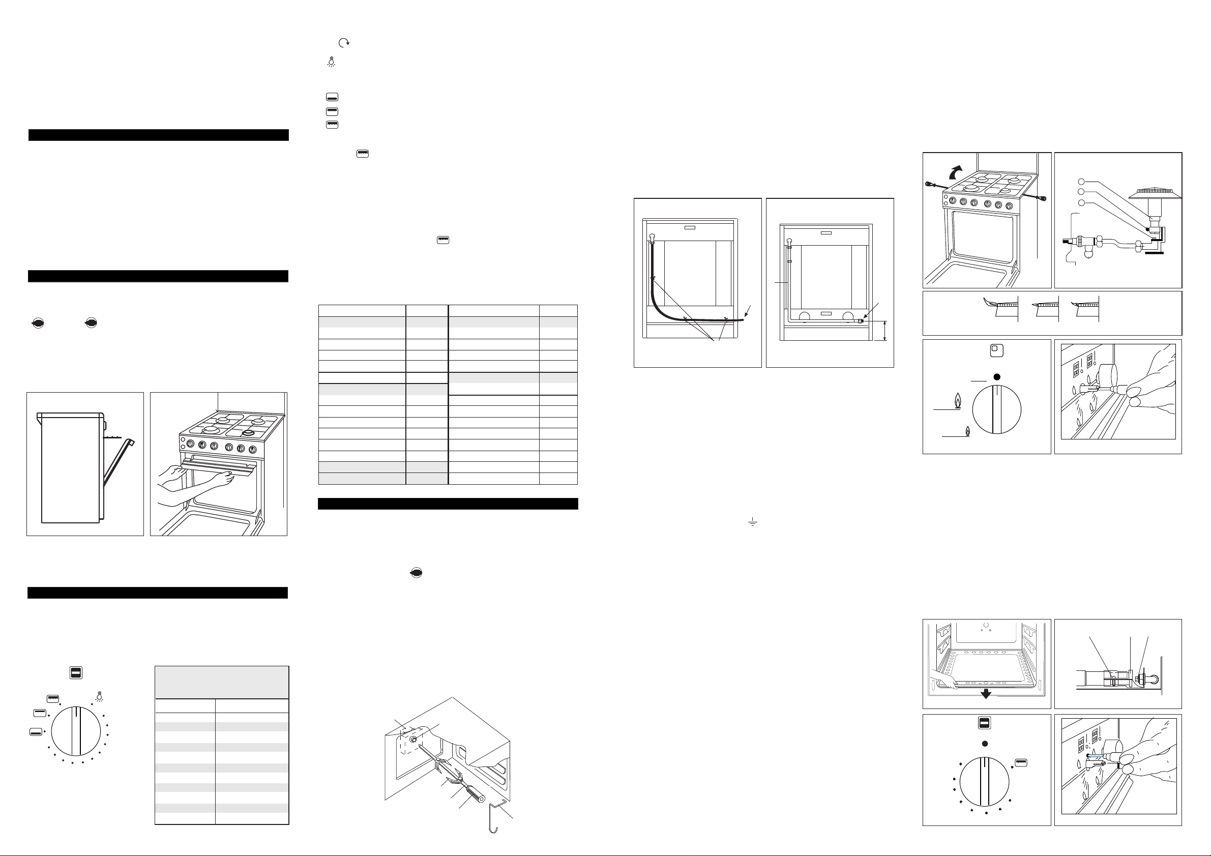
N.B. The connection between the end of the gas train and the supply can be made
on the right so that the gas pipe does not have to pass behind the cooker. In case
of connection on the left please relate to what already described in paragraph gas
connection having care to let the flexible tube pass through a holder see (fig. 5A)
in case of inflexible connection, see (fig. 5B).
BACK SIDE
B
Flexible tube entry
A
BACK SIDE
Inflexible tube entry
170
Fig. 5A Fig. 5B
3) ELECTRICAL CONNECTION
The appliance belong to class "X" against fire dangers (see N.B par. 1).
Connection of the appliance to the power mains should be done by a licensed
electrician familiar with local safety regulations.
- This appliance must be earthed by law.
- Before connecting the appliance to the electrical supply, check that the earth
system in your house is working correctly.
- Check that unit voltage and power, marked on the rating plate applied on the
appliance, are correct for the supply;
- It is necessary that the feeding network is protected by a powerful switch able
to disconnect completely the network with a contacts separation of at least 3
mm.
Be sure that the earth wire green/yellow is not interrupted by the switch.
Important: The wires in the mains lead are so coloured:
- green/yellow = earth “ ”
- blue = neutral “N”
- brown = live “L”
- The supply cable must not come into contact with any component the temperature
of which exceeds the ambient temperature by 50°C;
- If a plug is used for connection, the plug to be connected to the supply cable
and the socket to which it is connected must be of the same type (conforming
to the standards).
- Easy access to the plug or the switch is ensured once the appliance is installed;
- Ensure that there is sufficient cable allowed for any subsequent removal of the
unit.
The manufacturer declines all responsibility for any damage to persons or things
caused by failure to observe the rules indicated above.
4) CONVERSION FOR DIFFERENT TYPES OF GAS
The cooker carries a label specifying the type of gas for which it has been preset.
If it is to be used with a different type of gas, convert as follows with:
— Replacement of the hose attachment as in the previous section "Gas connection"
— Replacement of the nozzles and air adjustment.
4a) Hob
The nozzles are replaced as described below:
— Disconnect the electricity supply plug if present and close the gas tap installed
upstream of the appliance.
— Remove the hob pan stands, flame caps and burner cups.
— With a screwdriver remove the two screws locking the hob, raise it up and
secure it to prevent from falling back down (see fig. 6)
— Remove the nozzle (2 fig. 7) and screw on the new one suitable for the new
gas type (see chart 1).
— Regulate the flame by backing off the screw (4 fig. 7). Raise or lower the pipe
(3 fig. 7). The best flame conditions are shown in (fig. 8) (regulate with
burners hot if possible).
— Reassemble all components, following the above sequence in reverse order.
— Low flame setting (olso for oven with thermometer)
To obtain this, set the knob in the position where the gas tap opening is
minimum (this position is indicated by a small flame screen-printed on to the
fascia in fig. 9). Slide the knob off and adjust the inside screw coaxial with the
rod of the gas tap (hole in the centre of the knob mounting rod, fig. 10).
Tighten or back off the screw until the flame is brought down to the level
required. This adjustment must be made with the burner on.
When using liquid gas this screw must be fully tightened. After making this
adjustment check that the burner remains on when switched rapidly from full
heat to minimum position and viceversa.
Fig. 6 Fig. 7
3
4
2
Fig. 8
Max
Low
NO NO YES
Off
Fig. 9 Fig. 10
4b) Gas oven burner
— Remove the oven bottom (fig. 11).
— Unscrew the screws V (fig. 12) and remove the upper collar fixing the air muff
B (fig. 12) in order to have easier access to the nozzle.
— Remove the nozzle (F fig. 12) and screw on the one which is suitable for the
new type of gas (see chart 1).
— Regulate the flame by backing off the screws (V fig. 12) and move the pipe
(B fig. 12) backwards or forwards.
— Regulating the thermostat low flame position.
To do this, turn the oven to full heat (8) for about 10 minutes, then bring the
knob back to the minimum setting, position 1 (fig. 13). Remove the knob and
use the screw on the body of the thermostat (fig. 14) to set the flame size.
When using liquid gas this screw must be fully tightened.
After making this adjustment check that the burner remains on when switched
rapidly from full on to minimum position and viceversa.
Fig. 11 Fig. 12
1
2
3
8
7
6
Fig. 12
Fig. 11
4
5
14 3
 Loading...