

Zanussi ZT 1082 User Manual

WASHING MACHINE
ZT 102
ZT 1082
INSTRUCTION BOOKLET
124978193

CONTENTS
2
Important information .................Page 3
Installation .....................Page 4
n Unpacking ......................Page 4
n Positioning ......................Page 4
n Water inlet ......................Page 4
n Water drainage ....................Page 5
n Levelling ......................Page 6
n In the interest of the environment ................Page 6
n Electrical connection ...................Page 7
n Building-in ......................Page 8-9
Description of the appliance ...............Page 10
Technical specifications ................Page 10
Getting to know your machine ..............Page 11
n Control panel .....................Page 11
n Washing hints .....................Page 12
n Use of detergent and additives ................Page 13
n Programmes for cotton and linen ................Page 14
n Programmes for synthetics, delicates and wool ............Page 15
n Wash care symbols ...................Page 16
Using your machine ..................Page 17
n Washing 4.5 kg of white cotton at 95°C ..............Page 17
n Washing 2 kg of synthetic fabrics at 50°C .............Page 18
Maintenance and cleaning ...............Page 19
n Descaling, after each wash, external cleaning ............Page 19
n Cleaning the dispenser drawer, cleaning the drawer recess, the water inlet filters . . Page 19
n Cleaning the filter ....................Page 20
n The dangers of freezing ..................Page 20
Servicing ......................Page 21-22
Zanussi guarantee conditions ..............Page 23
Important
Your machine is fitted with a balance control device, which ensures the machine is stable during the
spin. If the wash load appears not to have been spun sufficiently at the end of the wash cycle, because it
is not evenly distributed in the drum, the balance control device may have operated. It will therefore be
necessary to redistribute the wash load manually and select a spin programme. For more detailed
information see the section headed "Servicing".

IMPORTANT INFORMATION
3
It is most important that this instruction book
should be retained with the appliance for future
reference. Should the appliance be sold or
transferred to another owner, or should you
move house and leave the appliance, always
ensure that the book is supplied with the
appliance in order that the new owner can get
to know the functioning of the appliance and
the relevant warnings.
These warnings have been provided in the
interest of safety. You MUST read them carefully
before installing or using the appliance.
Istallation
n
This appliance is heavy. Care should be taken
when moving it.
n
All packing and transit bolts must be removed
before use. Serious damage can occur to the
product and to property if this is not adhered to.
See relevant section in instructions.
n
Any plumbing work required to install this
appliance should be carried out by a qualified
plumber or competent person.
n
Any electrical work required to install this
appliance should be carried out by a qualified
electrician or competent person.
n
Care must be taken to ensure that the appliance
does not stand on the electrical supply cable.
n
If the machine is situated on a carpeted floor,
please adjust the feet in order to allow air to
circulate freely.
Use
n
Always unplug the appliance and turn off the
water after use.
n
Do not overload the appliance. See relevant
section in instruction book.
n
Only wash fabrics which are designed to be
machine washed. If in doubt, consult the care
label on the clothes.
n
Before washing, ensure that all pockets are
empty and buttons and zips are fastened. Avoid
washing frayed or torn articles and treat stains
such as paint, ink, rust, and grass before
washing. Underwired bras must NOT be
machine washed.
n
Any objects such as coins, safety pins, nails,
screws, stones or any other hard, sharp material
can cause extensive damage and must not be
placed into the machine.
n
Garments which have been in contact with
volatile petroleum products should not be
machine washed. If volatile cleaning fluids are
used, care should be taken to ensure that the
fluid is removed from the garment before placing
in the machine.
n
Wash small items such as socks, laces,
washable belts etc in a washing bag or pillow
case as it is possible for such items to slip down
between the tub and the inner drum.
n
Only use the advised quantities of fabric
softener. Damage to the fabric can ensue if you
over-fill. Refer to the manufacturer’s
recommendations of quantities.
n
As some duvets and eiderdowns should be
washed in large commercial machines because
of their bulk, please check with the manufacturer
of the item before washing in a domestic
machine.
n
Leave the porthole door slightly ajar between
washes to preserve the door seal.
Service/Repair
n
Under no circumstances should you attempt to
repair the machine yourself. Repairs carried out
by inexperienced persons may cause injury or
serious malfunctioning. Contact your local
Zanussi Service Centre. Always insist on
genuine Zanussi spare parts.
General Safety
n
It is dangerous to alter the specifications or
attempt to modify this product in any way.
n
This appliance is designed to be operated by
adults. Children should not be allowed to tamper
with the controls or play with the product.
n
Pets and children have been known to climb into
washing machines. Please check your drum
before use.
n
The glass door becomes very hot during the
washing cycle. Keep children away from the
vicinity of the appliance whilst it is in operation.
Environment protection
n The materials used on this appliance marked
with the symbol are recyclable.
This means that they can be recycled by
disposing of them properly in appropriate
collection containers.
n
When disposing of your old washing machine,
the electric cable must be cut off and the door
catch must be made unusable.

INSTALLATION
4
Unpacking
Before starting the machine up, the packing must
be removed as follows.
You are advised to keep all the packaging for reuse in case the machine is to be transported again.
Using a spanner unscrew and remove the rear right
bolt. Lay the machine gently on its back, making
sure that the hoses are not squashed.
Remove the polystyrene base and take off the
bottom panel by unscrewing the central screw.
Carefully slide out the right polythene bag.
Repeat the operation for the left and central
polythene bags.
Re-fit the bottom panel using the 4 screws supplied
with the door hinges (in the plastic bag) and the
previously removed screw.
P0453
P0016
P0015
P0457
P0255
Set the machine upright and remove the two
remaining bolts from the back.
Pull out the three plastic spacers from the holes
into which the bolts were fitted.
Plug the open holes with the plugs which you can
find at the back of the appliance.
Positioning
Install the machine on a flat hard floor.
Make sure that air circulation around the machine is
not impeded by carpets, rugs etc. Check that the
machine does not touch the wall or other kitchen
units.
Never place cardboard, wood or similar materials
under the machine to compensate for any
unevenness in the floor.
Your new washing machine has been designed to
be permanently plumbed in to your home’s water
supply and drainage system. However, if this is not
possible, it may be connected to suitable existing
taps with the drain hose discharging into a sink.
The appliance has two inlet hoses, hot and cold,
with female 3/4” BSP thread connectors. If this
connection is not compatible with the plumbing of
the existing installation, a variety of connectors are
available from good hardware stores and plumbers
merchants to suit most domestic plumbing. Any
alteration to your existing plumbing must be carried
out by a competent person, or qualified plumber.
Water inlet
The inlets on the back of the appliance are colour
coded, blue for cold and red for hot.
Before connecting the hoses be sure to fit the mesh
filters supplied as per diagram.
P0003
P0020
P0256
5
If only a cold water supply is available, connect the
two hoses to a cold water outlet by means of a «Y»
connection piece.
Installation should comply with local water authority
and building regulations’ requirements.
The appliance must be given a separate cold water
supply and not be connected to a mixer tap, a
single outlet water heater or a booster pump. A
minimum water pressure of 0.48 bar is required for
safe operation of the appliance.
If you cannot make the cold water connection direct
from the rising mains, you may be able to operate
the appliance from your cold water storage system.
There should be a minimum distance of 5.02m
(16
1
/
2
ft) between the appliance’s inlet and the
bottom of the water storage tank.
There will be sufficient pressure for the hot water
supply, providing there is a minimun height of 2.74
metres (9 ft) between the bottom of the cold water
storage tank and the bottom of the hot water
cylinder.
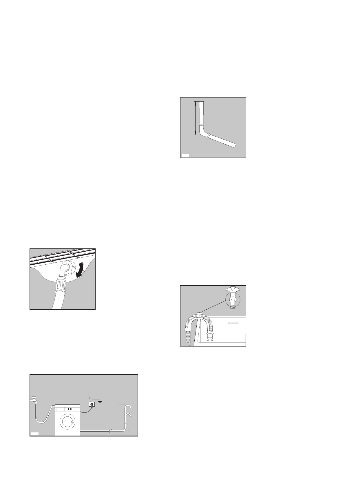
Set the hoses correctly by loosening the ring nuts.
After positioning the inlet hoses, be sure to tighten
the ring nuts again to prevent leaks.
Water drainage
This appliance is designed to be permanently
plumbed into your home's water supply and
drainage system.
The appliance drain hose should hook into a
standpipe, the hook in the drain hose is formed
using the plastic “U-Piece” supplied.
P1039
3 pin
Max. 90 cm.(35.4")
Min.60 cm.
(23.6")
P0021
The standpipe should have an internal diameter of
approximately 38mm (see diagram) thus ensuring
there is an air break between the drain hose and
standpipe.
When discharging into a standpipe ensure that the
top of the curve in the hose end is no more than
90cm (35.4'') and no less than 60cm (23.6'') above
floor level. The upright standpipe should have a
minimum length of 30cm (12'') from the bottom of
the elbow to the top of the pipe (see diagram).
Make sure that it is designed in such a way, that the
end of the drain hose cannot be covered with water.
The drain hose may be extended to a maximum of
4 metres. An additional drain hose and joining
piece is available from your local Service Force
Centre.
The joining piece must have an internal diameter of
18mm.
If you intend the drain hose to empty into a sink,
make sure that the sink is empty and the plug hole
is not blocked. Use the plastic “U-Piece” supplied.
Important
Before connecting up the machine to new pipework
or to pipework that has not been used for some
time, run off a reasonable amount of water to flush
out any debris that may have collected in the pipes.
P0022
P1040
Min. 30 cm.(12")
38 mm.(1/ ") diameter
standpipe
1
2
6
Levelling
Level the washing machine by raising or lowering
the feet. The feet may be tight to adjust as they
incorporate a self locking nut, but the machine
MUST be level.
Any necessary adjustment can be made with a
spanner. Accurate levelling prevents vibration, noise
and displacement of the machine during operation.
Some vibration is inevitable, especially if mounted
on a wooden floor.
Sprung wooden floors are particularly susceptible
to vibration. For advice, consult a builder. If
possible, always place the machine on a solid floor.
Special conditions
If the floor is carpeted with a deep-pile carpet or
covered with crumbly or soft material, insert a rigid
support base under the feet to prevent noise,
vibration or displacement. The base should
protrude a few centimetres beyond the edges of the
machine.
Warning
The machine should NOT be placed
on deep pile carpeting.
Note
Please ensure that when the appliance is installed
it is easily accessible for the engineer in the event
of a breakdown.
All plumbing and electrical work required to install
this appliance must be carried out by competent
persons or qualified plumbers or electricians.
P0850
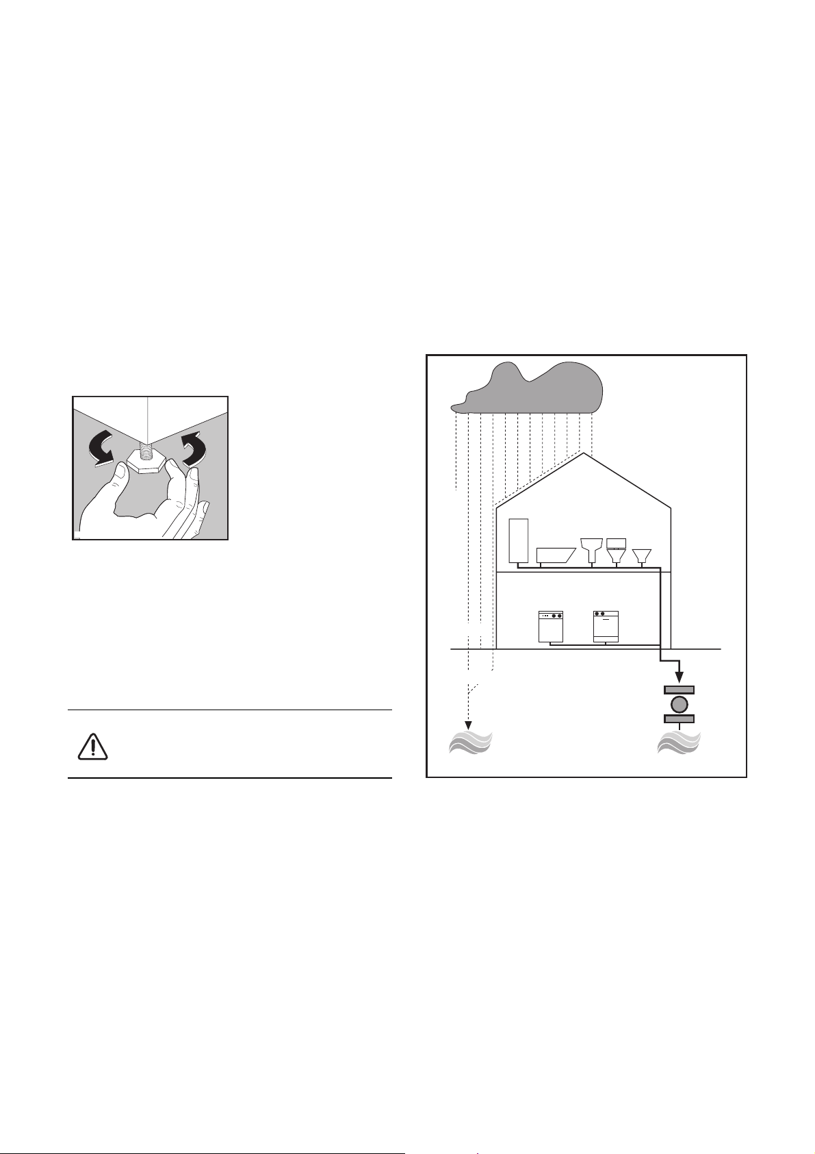
In the interest of the environment
Washing machines and dishwashers should be
connected to the FOUL drainage system, the water
will then be taken to a sewage works for treatment
before being discharged safely into a river.
It is essential that these appliances are not
connected to the surface water drainage system as
this water is discharged directly into a river or
stream and may cause pollution.
If you require any further advice please contact
your local authority drainage department.
SHOWER
BATH
SINK TOILET
BIDET
WASHING
MACHINE
DISHWASHER
RAINWATER
'RUN-OFF'
SURFACE WATER
DRAINS & SEWERS
UNTREATED
DISCHARGE
RIVER
FOUL DRAIN
FOUL SEWERS
SEWAGE
TREATMENT
WORKS
RIVER
P0987
TREATED
DISCHARGE
7
Electrical connection
Any electrical work required to install this appliance
should be carried out by a qualified electrician or
competent person.
WARNING: THIS APPLIANCE MUST BE
EARTHED.
The manufacturer declines any liability
should this safety measure not be
observed.
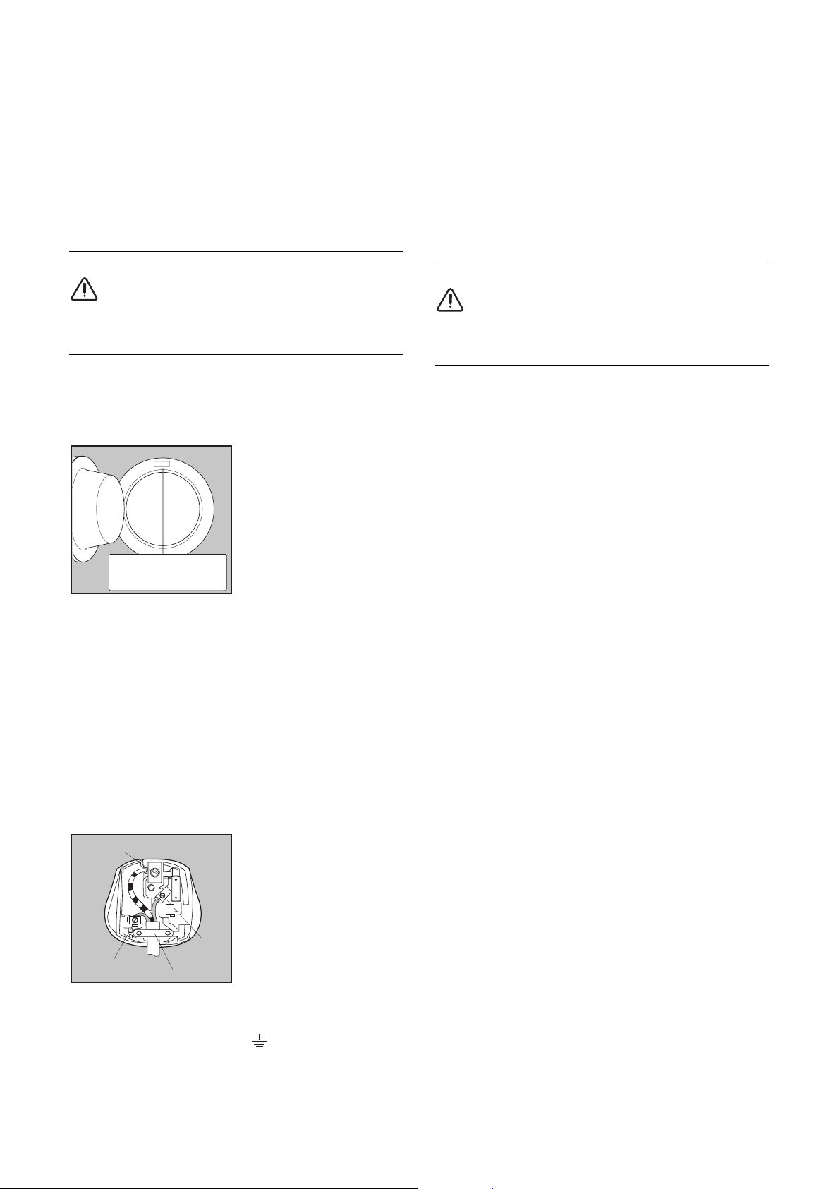
Before switching on, make sure the electricity
supply voltage is the same as that indicated on the
appliance’s rating plate. The rating plate is located
at the top of the rim of the open door.
The appliance is supplied with a 13amp plug fitted.
In the event of having to change the fuse in the
plug supplied, a 13amp ASTA approved (BS1362)
fuse must be used.
Should the plug need to be replaced for any
reason, proceed as described below.
The wires in the mains lead are coloured in
accordance with the following code:
Green and Yellow - Earth
Blue - Neutral
Brown - Live
The wire coloured green and yellow must be
connected to the terminal marked with the letter
«E» or by the earth symbol or coloured green
and yellow.
The wire coloured blue must be connected to the
terminal «N» or coloured black.
GREEN & YELLOW
BROWN
CORD CLAMP
BLUE
13A
P1041
E
N
L
Mod. ..........
Prod. No. ...........
Ser. No. .........
Mod.
..........
Ser.
P0042
The wire coloured brown must be connected to the
terminal marked «L» or coloured red.
Upon completion there must be no cut, or stray
strands of wire present and the cord clamp must
be secure over the outer sheath.
WARNING:
A cut off plug inserted into a 13 amp
socket is a serious safety (shock) hazard.
Ensure that the cut off plug is disposed of
safely.
Should the appliance power supply cable
neeed to be replaced, this should be carried
out by our Service Force Centre.
Permanent connection
In the case of permanent connection it is
necessary that you install a double pole switch
between the appliance and the electricity supply
(mains), with a minimum gap of 3mm between the
switch contacts and of a type suitable for the
required load in compliance with the current
electrical regulations.
The switch must not break the yellow and green
earth cable at any point.
8
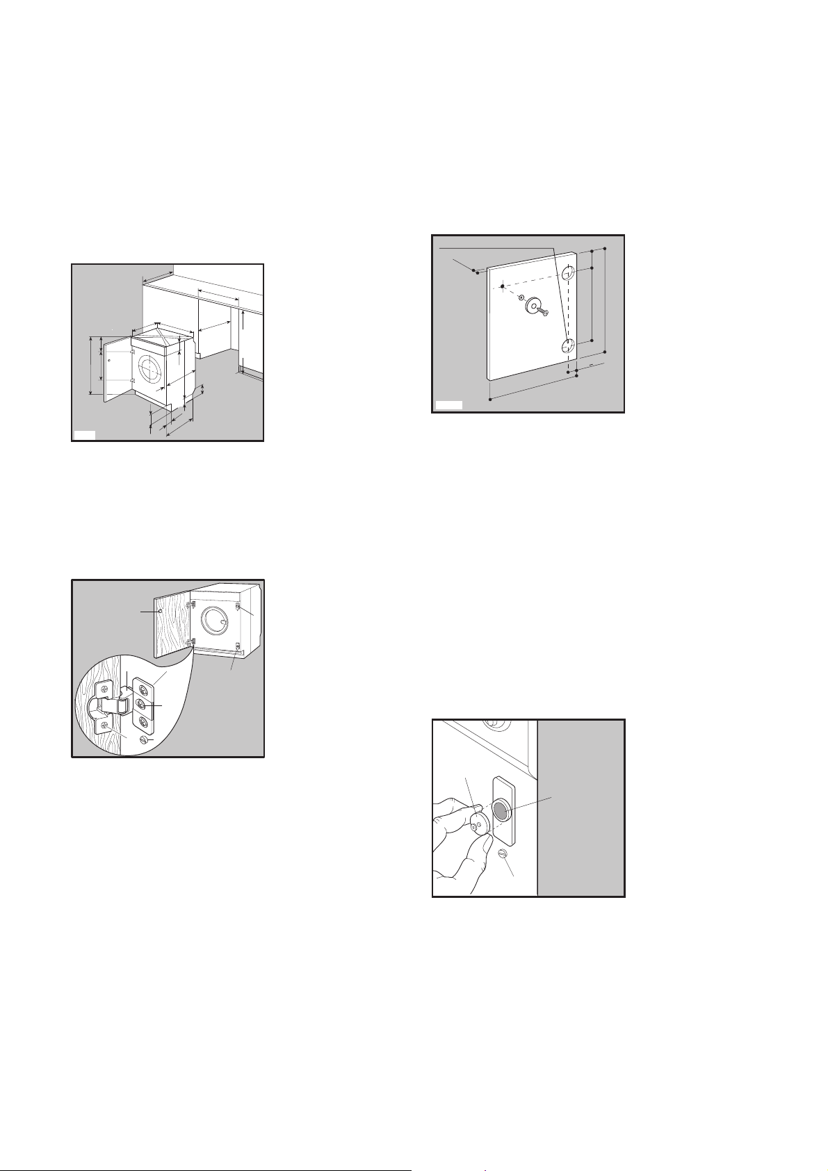
Building-in
This appliance has been designed to be built into
the kitchen furniture.
The recess should have the dimensions shown in
picture A.
Preparation and assembly of the door
The machine is originally pre-arranged for the
assembly of a door opening from right to left.
In this case it is sufficient to screw in the hinges (1)
and the counter-magnet (6) provided with the
appliance, at the right level (Fig. B).
a) Door
The dimensions of the door should be:
- width 595-598 mm
- thickness 16-22 mm
The height (C-Fig. C) depends on the height of the
adjacent furniture's base.
b) Hinges
To mount the hinges it is necessary to drill two
holes (dia. 35 mm, depth 12.5-14 mm depending
on the depth of door furniture) on the inner side of
the door. The distance between the holes hobs
fixing centres must be 416 mm.
The distance (B) from upper edge of the door to
the centre of the hole depends on the adjacent
furniture's dimensions.
4
1
2
3
6
1
2
3
P0982
7
8
B
5
P0965
820 min
570 min.
600
596
416
176,5
818
541
195
490
160
120
90
8
515
165
A
600
The required dimensions are given in the picture C.
The hinges will be fixed to the door by means of
screws for wood (2-Fig. B) supplied with the
appliance.
c) Mounting the door
Fix the hinges (1) to the machine by means of the
M5x8 screws (3-Fig. B). The hinges can be
adjusted to compensate for possible uneven
thickness of the door.
To align the door perfectly it is necessary to loosen
the screw (3-Fig. B), adjust the door and tighten
the screw again.
d) Counter-magnet (6)
The appliance is pre-arranged for a magnetic
closure of the door. To enable a correct operation
of this device, it is necessary to screw the countermagnet (6) (steel disk + rubber ring) into the inner
side of the door.
Its position must correspond to the magnet (4) on
the appliance (see picture D).
P0984
6
4
8
D
35 Ø 12.5-14 depth
16-22
B
C
22+1,5
595-598
416
P0422S
C
 Loading...