

Zanussi ZHT 61, ZHT 91 installation guide

WARNING
---------------------------------------------------
The distance between the hob and the lower
part of the hood must be at least 65 cm.
The air collected must not be conveyed into
a duct used to blow off smokes from appliances fed with an energy other than
electricity (central heating systems, thermosiphons, water-heaters, etc.).
Comply with the official instructions provided
by the competent authorities in merit when
installing the disposal duct. In addition,
exhaust air should not be discharged into a
wall cavity, unless the cavity is designed for
that purpose.
The room must be well aerated in case a
hood and some other heat equipment fed
with an energy other than electricity (gas, oil,
coal heaters, etc) operate at the same time.
In fact the intake hood, disposing of air, could
create a vacuum in the room. The vacuum
should not exceed 0,04mbar. This prevents
the gas exhausted by the heat source from
being intaken again. It is therefore advisable
to ensure the room contains air taps able to
ensure a steady flow of fresh air.
This appliance has such technical particulars that it belongs to class II insulation, therefore it must not be earthed.
When making the electrical connections,
check that the voltage values correspond to
those indicated on the data plate inside the
appliance itself.
In case your appliance is not furnished with
a non separating flexible cable and has no
plug, or has not got any other device ensuring omnipolar disconnection from the electricity main, with a contact opening distance
of at least 3 mm, such separating device
ensuring disconnection from the main must
be included in the fixed installation.
Always switch off the electricity supply before carrying out any cleaning or servicing
operations on the appliance.
USE
--------------------------------------------------
Avoid using materials which could cause
spurts of flame (flambÈes) near the appliance.
When frying, take particular care to prevent
oil and grease from catching fire. Already
used oil is especially dangerous in this respect. Do not use uncovered electric grates.
To avoid possible risks of fire always comply
with the indicated instructions when cleaning
anti-grease filters and when removing grease
deposits from the appliance.
MAINTENANCE
--------------------------------------------------
Thorough servicing guarantees correct and
long-lasting operation.
Use lukewarm water and neutral detergent
to clean painted appliances. Never use
products containing abrasives.
Take great care to prevent the use of corrosive or abrasive products when cleaning
steel, copper or brass appliances. It is
advisable to use specialized products
according to the manufacturerís instructions.
DESCRIPTION
--------------------------------------------------
The appliance can be used both in Ducting version
and Filtering version.
In the Ducting version (Fig. 1), cooking vapours
and/or odours are conveyed straight outside
(ceiling and/or wall) by a disposal duct, using the
holes that are predisposed on the top and/or at the
back of the apparatus.
In the Filtering version (Fig. 2) cooking vapours
and/or odours are depurated by a special activated
vegetal charcoal fiber panel and recirculated
around the room by the front fissures. ATTENTION:
For the filtering version it is absolutely necessary
to use the special active vegetal charcoal fiber
panel whereas for the ducting version it is not.
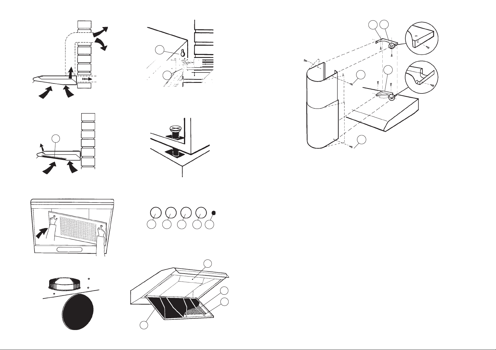
INSTALLATION
--------------------------------------------------
Before assembling the appliance it is necessary to
take off the anti-grease grille. To take off the grill
it is necessary to push this one towards the rear of
the apparatus, by means of the proper knobs, so
that it gets released, and to pull it downwards; to
take it off completely, make it rotate on one side
keeping the other one steady (Fig. 3).
For the ducting installation of the appliance, connect
one of the two discharge outlet to the external
ducting and seal the other opening with the supplied
cap (Fig. 4). For the filtering installation you must
close both the discharge outlets of the apparatus
using the supplied caps.
The following operations are essential for assembly:
ñ Install a proper wiring system.
ñ If your apparatus is to be assembled as a
Ducting appliance, you must first make the air
venting hole and get a proper pipe to connect
the hole to the flange of the hood.
Wall fitting
Making use of the appropriate drilling jig, apply the
supplied blocks into the wall. Insert two of the
supplied screws so that the apparatus can be
hooked onto these ones by means of the holes
provided on the appliance (Fig. 5A). Once the
apparatus is hooked, fix it definitively to the wall
using the two other screws and the holes made at
its bottom (Fig. 5B). To avoid damage make
exclusive use of the holes already prepared on the
hood. Make the electrical connections.
Wall cupboard fitting
Using the appropriate drilling jig make the four fixing
holes into the bottom of the wall cupboard and cut
the air venting hole if the hood is a ducting version
one (for the filtering version this hole is not
necessary). Holding the hood against the bottom
of the cupboard fix it to it by means of the supplied
four screws (Fig. 6). Make the electrical
connections.
IMPORTANT:
Check the position of screw A (Fig. 8). For the
ducting version screw A must be completely
screwed; for the filtering version the screw
must be completely unscrewed to let the sucked
air to get out through the top fissures.
ASSEMBLY OF THE DECORATIVE PIPE
AVAILABLE AS ACCESSORY
--------------------------------------------------
Fix the lower bracket A onto the apparatus (Fig.
9). Fix the upper bracket B onto the ceiling; in
order to position the bracket on the same axis
as your apparatus, refer to the small triangle C
that is on the central axis. Take the two telescopic
pipes minding that you have to lift slightly the
smaller pipe (the upper one); insert the pipes
from the front, expanding slightly with your hands
so that they can get hooked onto the two
brackets. Fix the pipes to the brackets by means
of the screws D and E.
OPERATION
--------------------------------------------------
A = light switch (Fig. 7).
B = first speed motor ON/OFF switch.
C = second speed switch.
D = third speed switch.
E = warning light: indicates motor operation.
Filtering/ducting conversion:
The conversion can be done in the inside of the
appliance. Access is possible by opening the grille
as described beforehand. Verify that screw A (Fig.
8) is completely unscrewed, so that the inside valve
let the air to be conveyed again into the room throuth
the slots. Insert the activated charcoal fiber panel
(Fig.2F and 8F): lift the two stops made of metallic
wire (Fig. 8C); insert the fiber panel and set back
the two stops.
In case the hood is a filtering version one, it is
necessary to change the activated charcoal fiber
panel (Fig.2F and 8F) according to utilization about
every six month. To remove the fiber panel:
ñ take off the anti-grease grill: by means of the
proper knobs make the grill move towards
the rear of the apparatus and drop the front
part of it; now, keeping the right (or left) side
of the grill steady, make the opposite side
rotate so that it gets off the hood (Fig.3).
ñ lift the two metallic stops (Fig. 8C).
ñ remove the fiber panel.
The anti-grease filtering panel is easily removed
from the grille by opening it as described above
and lifting the two stops made of metallic wire (Fig.
8C). In the filtering version, to get access to the
anti-grease panel the activated charcoal fiber panel
must be removed too. Change the anti-grease panel
according to use. If the panel is a metallic one it can
be washed with some neutral detergent by hand or
in a dish-washer.
To gain access to the light bulb(s), remove the
anti-grease grill as described above and remove
the bulb(s). Replace with lamps of the same type.
1
5
9
B
C
2
3
A
B
D
A
D
E
6
F
E
7
4
8
A
B
C D E
A
B
C
F
 Loading...