

Page 1

MODE D'EMPLOI BEDIENUNGSANLEITUNG
GEBRUIKSAANWIJZING OPERATING INSTRUCTIONS
FOURS
MULTIFONCTIONS
MULTIFUNKTION
EINBAU-HERDE
MEER - SYSTEMEN
INBOUW-FORNUIZEN
MULTIFUNCTION
BUILT-IN OVEN
52
ZHM 761
Page 2

ENGLISH
Madam,
Congratulations on having chosen a quality product from our company. This appliance is very easy to use.
Nonetheless, in order to obtain the maximum profit from your new appliance, we suggest you spend a few minutes
reading this brochure.
You will find the correct indications for installation, use and mainteinance.
We thank you and hope you will enjoy using this new appliance.
CONTENTS
Warnings and important advice page 54
Using the oven Page 55
How to set the electronic timer Page 57
When the oven is first installed Page 58
Cooking with the multifunction oven Page 58
Cooking tables Page 60
Using the Grill Page 61
Cleaning and Maintenance Page 61
If something goes wrong Page 64
Assistance and spare parts Page 64
Guarantee conditions Page 65
Technical data Page 66
To the attention of the installer Page 67
Electrical connection Page 69
53
Page 3
WARNINGS AND IMPORTANT ADVICE
These warnings are provided in the interest of safety. You MUST read them carefully before
installing or using the appliance.
It is most important that this instruction book should be retained with the appliance for future
reference. Should the appliance be sold or transferred, always ensure that the book is left with
the appliance in order that the new owner can get to know the functions of the appliance and
the relevant warnings.
• This appliance has been designed to be operated by
adults and children under supervision. Young children
MUST NOT be allowed to tamper with the controls or
play near or with the oven.
• This appliance has been designed for cooking
edible foodstuff only and MUST NOT be used for any
other purposes.
• It is dangerous to alter the specification in any way.
• For hygiene and safety reasons, this appliance should
be kept clean at all times. A build-up of fats or other
foodstuff could result in a fire.
• Accessible parts of this appliance may become hot
when it is in use. Children should be KEPT AWAY until
it has cooled.
• Under no circumstances should you attempt to repair
the appliance yourself. Repairs carried out by
unexperienced persons may cause injury or serious
malfunctioning. Refer to your local Zanussi Service
Centre. Always insist on genuine Zanussi spare
parts.
• Ensure that all control knobs are in the OFF position
when not in use.
• Should you connect any electrical tool to a plug near
this cooking appliance, ensure that electric cables
are not in contact with it and keep them far enough
from the heated parts of this appliance.
• If the appliance is out of order, disconnect it from the
electric supply.
• Do not leave untensils containing foodstuffs, e. g. fat
or oil in or on the appliance. This could cause
damage in case the appliance is inadvertently
switched on.
• Always place the dripping pan in position to
collect fat when using the grill or when cooking
meat. Pour a little water into the dripping pan to
avoid smoke and unpleasant smells.
• Always use oven gloves to remove pans from the
oven.
• It is mandatory that all operations required for the
installation are carried out by a qualified or competent
person, in accordance with existing rules and
regulations.
• Disconnect the appliance from the electrical supply,
before carrying out any cleaning or manteinance
work.
• Some parts of the appliance are covered by a shockproof plastic film. Remove this film before using the
oven.
• Once you removed all packaging from the appliance,
ensure that it is not damaged and the electric cable
is in perfect conditions. Otherwise, contact your
dealer before proceeding with the installation.
• This appliance is meant to operate with a singlephased connection to 230V electrical supply. An
eventual 400V poliphasic connection without earth
wire will destroy the oven and the hob, if fitted.
• The manufacturer disclaims any responsability
should all the safety measures not be carried
out.
54
OVEN DOOR PROTECTION DEVICE
(MOD. ZHM 761 X)
All our appliances comply with the European Safety
Standards. Nevertheless, in order to ensure the
highest safety level, and avoid little children to be
exposed to the heat when the appliance is operated,
it is possible to fit a special protection device to the
oven door. This device can be purchased in our
Service Force Centres, specifying the relevant code
(35791) and the Product No. shown on the rating
plate. Fitting instructions are provided with the kit
package.
Page 4
USING THE O VEN
0
ZHM 761
- +
Programmer
Thermostat
Control Light
ZHM 761 X
- +
Oven Function
Control Knob
Thermostat
Control Knob
Oven
Control Light
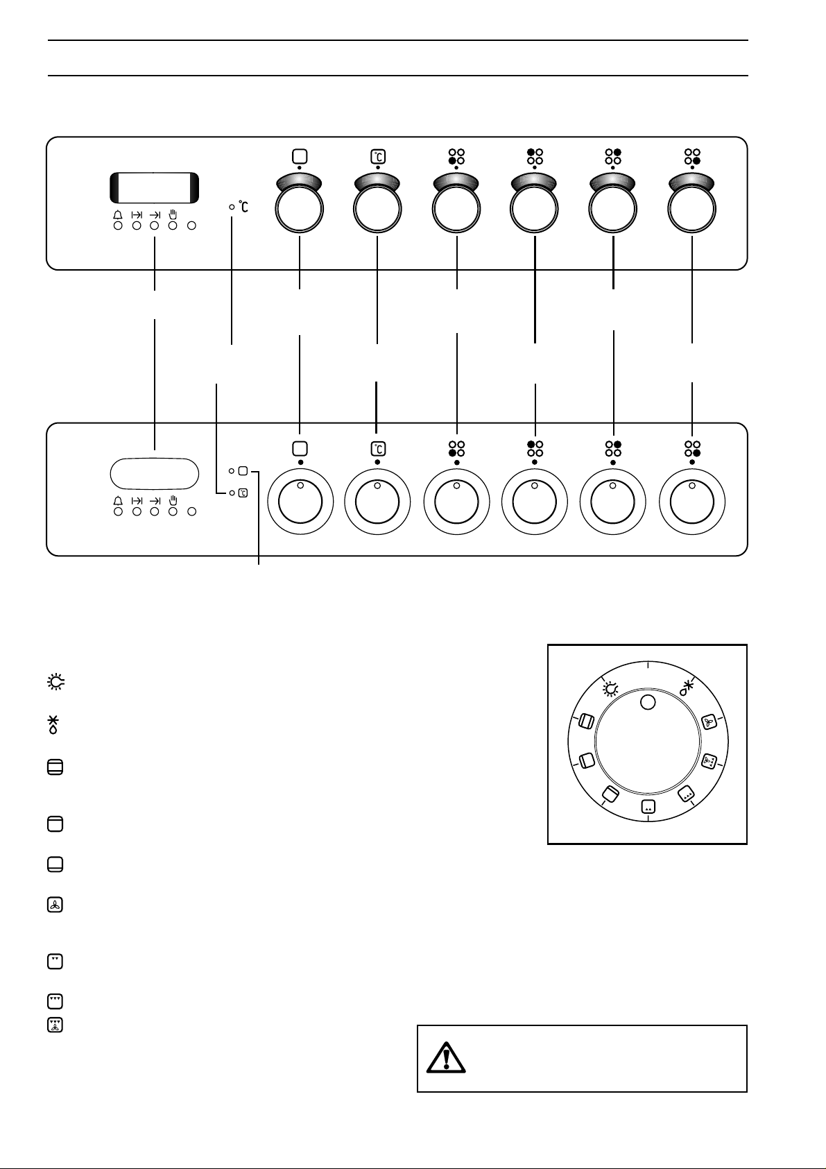
OVEN FUNCTION CONTROL KNOB (FIG. 1)
Oven Light - The oven light will be on without any
cooking function
Control Knob for
front left hotplate
Control Knob for
rear left hotplate
Control Knob for
rear right hotplate
Control Knob for
front right hotplate
Defrost Setting - This setting is intended to assist
in thawing of frozen food.
Conventional cooking - The heat comes from both
the top and bottom element, ensuring even
heating inside the oven.
Top heating element - The heat comes from the
top of the oven only.
Bottom heating element - The heat comes from
the bottom of the oven only.
Fan cooking - This allows you to roast or roast
and bake simoultaneously using any shelf,
without flavour transference.
Inner grill element only - can be used for grilling
small quantities.
Double Grill - The full grill element will be on.
Thermal Grilling - This function offers an alterna-
tive method of cooking food items, normally
associated with conventional grilling. The grill
element and the oven fan operate together,
circulating hot air around the food.
Fig. 1
FO 0347
All cookings must be carried out
with the oven door closed
55
Page 5
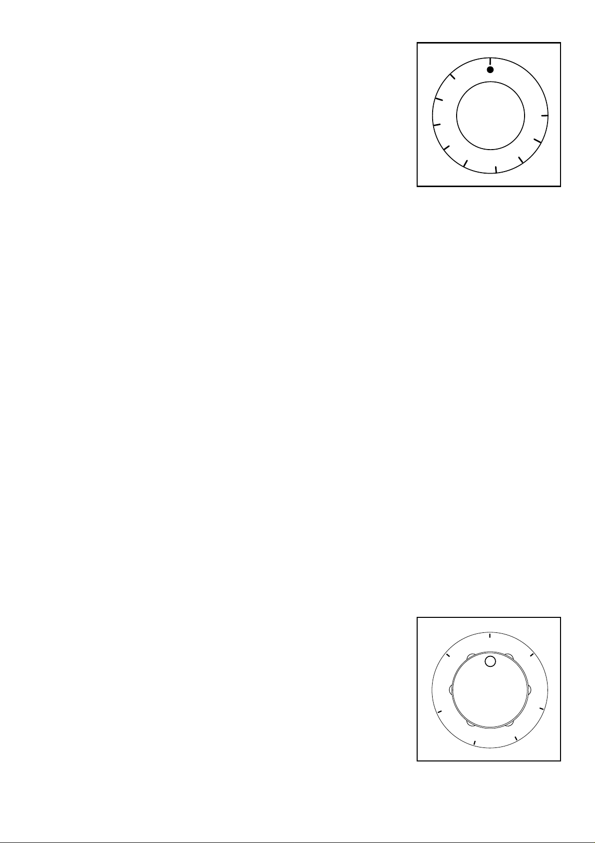
THERMOSTAT CONTROL KNOB (FIG. 2)
0
1
2
3
Turn the thermostat control knob clockwise to select
temperatures between 50°C and 250°C (MAX).
50
OVEN CONTROL LIGHT
This yellow light will come on when the oven function
control knob is set on a function.
THERMOSTAT CONTROL LIGHT
Once the oven temperature has been selected, the
Themostat Control Light will come on and remain on
until the oven has reached the correct setting; after that,
it will go on and off with the thermostat, showing how the
temperature is being maintained.
THE SAFETY THERMOSTAT
This oven is provided with a safety thermostat. In case
of malfunctioning of the main thermostat, and consequent
over-heating, the safety device will stop the power
supply to the appliance. If this happens, call your local
Zanussi Service Centre. Under no circumstances should
you attempt to repair the appliance yourself.
THE COOLING FAN FOR THE CONTROLS
This oven is provided with a cooling fan, meant to keep
the front panel, the knobs and the oven door handle
cool. This fan may run on after the oven or grill is
switched off, until a normal temperature is reached.
Fig. 2
MAX
100
200
150
FO 0282
CATALYTIC SELF-CLEANING
SIDE PANELS
(accessory available on request)
Catalytic self cleaning panels can be installed onto the
sides of the oven. These panels, at normal cooking
temperature, can turn the splashes of fat into a light
residual powder.
This powder must be removed with a damp sponge after
the oven has cooled down, in order to keep the catalytic
panels in good condition.
HOTPLATE CONTROL KNOBS
The Control Knobs for the hotplates (Fig. 3) can be found
on the Oven Control Panel.
The energy regulator of the hotplates can be set by
means of a 7 positions control knob.
0 = OFF
1 = MINIMUM
3 = MAXIMUM
The intermediate positions give an increasing heating
power.
Carefully supervise cookings with fats or oil, since
these types of foodstuff can result in a fire, when over-
heated.
Fig. 3
FO 2168
56
Page 6
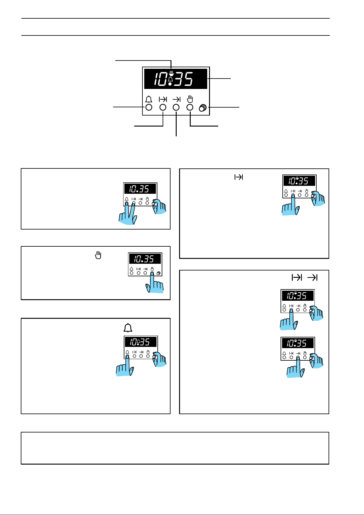
ELECTRONIC TIMER
Program On
Light
A
A
U
U
T
T
O
O
Automatic
Operation
Light
A button: Minute Minder
Acoustic Signal Off
B button:
Cooking Time
End of Cooking
SETTING THE TIME OF DAY (24 H CLOCK)
Press buttons A and B at the
same time and while turning
knob E enter the time of day.
- +
MANUAL OPERATION
- +
To set oven for manual operation,
press button D.
SETTING THE MINUTE MINDER
Press button A and while
turning knob E enter the
required time (maximum 23 h
59 min.) After required time
has been selected the clock
will revert to the time of day.
When time is up an audible
signal will be heard for approximately 2 minutes. To
cancel press button A and return control and
thermostat knobs to the OFF position.
- +
- +
KNOB (E)
D button:
Manual Operation
C button:
COOKING TIME
Press button B and while turning
knob E enter the required time.
The "AUTO" signal will appear on
the right hand side of the clock.
Then, select the required temperature and the oven
function. When cooking is completed, an audible
signal will be heard for approximately 2 minutes.
To cancel press button A and return control and
thermostat knobs to the OFF position.
SETTING THE AUTOMATIC TIMER
Press button B and while
turning knob E enter the
required cooking time.
Then press button C and while
turning knob E enter the end of
cooking time.
Turn the thermostat and
function control knobs to the
required settings. The oven
temperature light nor oven light
will not come on until the oven
switches on. When cooking is
completed, the "AUTO" signal
will flash an audible signal will
be heard for approximately 2 minutes. To cancel
press button A and return control and thermostat
knobs to the OFF position.
A
A
U
U
T
T
O
O
- +
A
A
U
U
T
T
O
O
- +
A
A
U
U
T
T
O
O
- +
In case of loss of power, all the settings (time of day, setted programs or programs in operation) will
be cancelled. When the power is restored, the numbers on the display will flash, and the timer has to
be reset.
57
Page 7

WHEN THE OVEN IS FIRST INSTALLED
Once the oven has been installed:
a) set the thermostat knob to MAX;
b) switch the oven function control knob to
conventional cooking ( );
c) allow the oven to run empty for approximately
45 minutes;
d) open a window for ventilation.
During this time, an unpleasant odour may be emitted.
This is absolutely normal, and is caused by residues of
manufacturing.
Once this operation is carried out, let the oven cool
down, then clean the oven cavity with a soft cloth soaked
in warm soapy water.
Before cooking for the first time, carefully wash the shelf
and the dripping pan.
To open the oven door, always catch
the handle in its central part (Fig. 4).
Fig. 4
FO 2161
COOKING WITH THE MULTIFUNCTION OVEN
CONVENTIONAL COOKING
Turn the oven function control knob to the relevant
symbol ( ) and set the thermostat knob on the
required temperature.
If you need more heat from the bottom or from the top,
turn the oven function control knob to (top heating
element only) or (bottom heating element only).
THE FAN OVEN ( )
Turn the oven function control knob to the relevant
symbol ( ) and set the thermostat knob on the
required temperature. The fan behind the back panel
circulates heated air into the oven.
If you need to cook more than one dish in the fan oven
at the same time, place the shelves on the first and third
position from the bottom. If you are cooking only one
dish in the fan oven, use the lower positions, as this will
give you better results.
DEFROSTING
Turn the oven function control knob to the relevant
symbol ( ) and set the thermostat knob on the OFF
position (symbol : ●). The oven fan operates without
heat and circulates the air, at room temperature, inside
the oven.
• The temperatures inside the oven can reach 250°C.
Always ensure that you are using oven proof baking
trays, oven dishes, etc.
• Do not place pans, biscuit pans or aluminium foil
directly on the base of the oven. This could cause a
heat build-up which could affect the performance of
the oven and damage the oven enamel.
• Carefully supervise cookings with fats or oil, since
these types of foodstuff can result in a fire, if overheated. For the same reason, be careful when
placing or removing food in the oven, not to let any
fat or oil fall on the oven base. If this happens,
carefully clean the oven to avoid unpleasant smells
or smoke.
58
Page 8

HINTS AND TIPS ON COOKING FISH AND
MEAT
You can place meat in oven proof dishes, or directly on
the oven shelf. In this case, remember to place the
dripping pan in the first position from the bottom with
some water in it. The dripping pan will avoid the falling
of melted fat on the oven base.
White meat, poultry and fish in general, need a medium
temperature cooking (between 150 and 175 ° C). If you
need to cook red meat (slightly browned on the outside
and more gently cooked in the inside), a higher temperature (between 200 and 250 ° C) for a short time is
recommended.
HINTS AND TIPS ON BAKING
Cakes usually need a medium temperature cooking,
between 150 and 200 °C.
A short oven pre-heating (about 10 minutes) is
recommeded when cooking cakes or baking. Once the
cooking has been started, keep the oven door closed
during all the cooking time, and check the cooking
results through the oven door glass.
HINTS AND TIPS ON GRILLING
If you need to grill meat or fish, place them directly on the
shelf after spreading a little oil on them. In the grill
function, heat comes only from the top element.
Therefore, you need to adjust the cooking level
depending on meat or fish's thickness. Always remember
to place the dripping pan in the lower position with some
water in it.
GRILLING
Turn the oven function control knob to the relevant
symbol ( or ) and set the thermostat knob on the
required temperature. With the setting , you will
obtain even heating on the whole surface of the dish.
When grilling meat or fish, spread a little oil on them and
always place them on the oven grid. The shelf level
depends on the thinckness of the food.
Always place the dripping pan at the lowest level, with
some water in it, to avoid smoke and unpleasant smells.
THERMAL GRILLING
Turn the oven function control knob to the relevant
symbol ( ) and set the thermostat knob on the
required temperature. Select a maximum temperature
of 200°C.
The full grill element and the oven fan operate alternately,
circulating hot air around the food. The need to check
and turn food is reduced. With the exception of toast and
rare steaks, you can thermal grill all the foods you would
normally cook under a convetional grill.
GREASE FILTER
When cooking meat, the grease filter must be fitted
over the oven fan by clipping it over the vents in the
back panel. This will prevent a built-up of fat on the fan
impellor. Do not use abrasive materials to clean the
seal. The grease filter is dishwasher proof.
When cooking is completed and the oven has cooled
down, remove the filter by pushing the protruding
tongue on the filter upward. (See Fig. 5)
Fit the gease filter only when roasting.
FO 0018
Fig. 5
59
Page 9

COOKING TABLES
TRADITIONAL COOKING AND FAN DUCTED COOKING
WEIGHT
(GR.)
TYPE OF DISH
Level
4
3
2
1
temp.
°C
Level
Fan OvenTraditional Cooking
4
3
temp.
2
1
°C
time
minutes
NOTES
Cakes
Cooking
Whipped up kneading
Leavened kneading
Shortbread dough
Butter-milk cheese cake
2 180 2 (1 and 3)* 160 45 ~ 60
2 180 2 (1 and 3)* 160 20 ~ 35
2 180 2 (1 and 3)* 160 20 ~ 30
1 175 2 150 60 ~ 80
Apple cake 1 180 2 (1 and 3)* 160 40 ~ 60
Strudel 2 175 2 (1 and 3)* 150 60 ~ 80
Jam-tart 2 180 2 (1 and 3)* 160 45 ~ 60
Small cakes 2 180 2 (1 and 3)* 160 15 ~ 25
Biscuits 2 180 2 (1 and 3)* 160 10 ~ 20
Meringues 2 100 2 (1 and 3)* 100 90 ~ 120
Bread and Pizza
1000 White bread 1 200 2 175 45 ~ 60 1 piece
500 Rye bread 2 200 2 175 30 ~ 45 In bread pan
500 Bread rolls 2 200 2 (1 and 3)* 175 20 ~ 35 8 rolls
250 Pizza 1 220 2 (1 and 3)* 200 20 ~ 35 In baking pan
Flans
Pasta flan 2 200 2 (1 and 3)* 175 40 ~ 50
Vegetable flan 2 200 2 (1 and 3)* 175 45 ~ 60
Quiches 2 200 2 (1 and 3)* 175 35 ~ 45
Lasagne 2 200 2 175 45 ~ 60
Meat
1000 Beef 2 200 2 175 50 ~ 70 On grid
1200 Pork 2 200 2 175 100 ~ 130 On grid
1000 Veal 2 200 2 175 90 ~ 120 On grid
1500
English roast beef
2 220 2 200 50 ~ 70 On grid
1200 Lamb 2 200 2 175 110 ~ 130 Leg
1000 Chicken 2 200 2 175 60 ~ 80 Whole
4000 Turkey 2 200 2 175 210 ~ 240 Whole
1500 Duck 2 175 2 160 120 ~ 150 Whole
3000 Goose 2 175 2 160 150 ~ 200 Whole
1200 Hare 2 200 2 175 60 ~ 80 Cut in pieces
Fish
1000 Whole 2 200 2 (1 and 3)* 175 40 ~ 60 2 fishes
800 Fillets 2 200 2 (1 and 3)* 175 30 ~ 40 4 fillets
NOTE:
Cooking times do not include pre-heating time. We
reccomend a short oven pre-heating (about 10
minutes) before baking or cooking pizza.
60
(*) If you need to cook more than one dish at the same
time, we recommend you to place them on the levels
quoted between brackets.
Page 10

COOKING TABLES - GRILLING
GRILLING
Quantity
TYPE OF DISH
PIECES WEIGHT
Steaks
Chops
Sausages 8 500 4 max 10 6
Chicken (cut in pieces)
Kebabs 4 700 4 max 12 10
Chicken (breast) 4 400 4 max 13 10
Tomatoes 8 500 4 max 12 —
Fish (fillets) 4 400 4 max 8 6
Sandwiches 4 — 4 max 8 —
Toast 4 — 4 max 2~3 1
4 800 4 max 10 8
4 600 4 max 12 8
6 800 3 max 30 20
Level
Grilling
4
3
2
1
temp.
Cooking time
Upper
°C
(minutes)
side
Lower
side
THERMAL GRILLING
Type of dish Quantiy (gr.) Shelf level Temperature °C Time in minutes
from the bottom lower side upper side
Pork 1500 2 or 3 170 45 30
Roastbeef 1500 3 200 30 20
Chicken 1200 2 or 3 190 40 30
Kebabs 800 3 200 15 10
Fish (whole) 800 3 200 12 8
61
Page 11

CLEANING AND MAINTENANCE
General Cleaning
• Before cleaning, always allow the oven to cool
down.
• When using spray cleaning products, be careful not
to spread them on the heating elements or on the
thermostat sensor.
• Never use harsh abrasives, steel wool or cleaners
with bleach, as they could damage the enamel and
the oven door glass.
The Oven Cavity
The enamelled oven cavity is best cleaned whilst the
oven is still warm. It is advisable to wipe the oven over
with a soft cloth soaked in warm soapy water after each
use. However, from time to time, it will be necessary to
do a more complete cleaning, using a proper oven
cleaner.
In case of particularly tough stains, you can use stainless
steel cleaning products or some warm vinegar.
• If cooking fruits, some over-heated natual acids
can squeeze and settle on the oven enamel, causing
stains quite difficult to remove. This could affect the
enamel brightness, but it will have no consequence on
the oven performances. To avoid these stains to be
burnt out during the next cooking, carefully clean the
oven cavity after all fruits cookings.
Fig. 6
Fig. 7
FO 0288
FO 0027
The Oven Door and its gasket
Before cleaning the oven door, we recommend you to
remove it from the oven.
Proceed as follows:
a) open the oven door completely;
b) find the hinges linking the door to the oven (fig 6);
c) unlock and turn the small levers located on the two
hinges (fig. 5);
d) handle the door by its left- and right-hand sides, then
slowly turn it towards the oven until it is half-closed;
e) gently pull the oven door off its site (fig. 6);
f) place it on a steady plan;
g) unscrew the two screws marked with lett. A fig.7;
h) pull up the oven door glass and take it away from the
oven door.
Clean the oven door glass with warm water and a softh
cloth only.
Once the cleaning is carried out, refit the oven door,
following the procedure in reverse.
The correct operation of the oven is ensured by a gasket
placed round the edge of the oven cavity.
• Periodically check the condition of this gasket. If
necessary, clean it without using abrasive cleaning
products.
•
If the gasket shows to be damaged, call you local
Zanussi Service Centre. Do not use the oven until it
has been repaired.
Fig. 8
FO 0287
Replacing the Oven Light
• Ensure the electricity supply is switched off before
carrying out this operation.
The oven bulb has to comply to these features:
a) resistant to temperatures of 300 °C;
b) electric rate: 230 V - 50 Hz;
c) electric power rate: 25 W.;
d) connection type: E 14.
To replace the bulb, proceed as follows (Fig. 8):
a) push in and turn the glass lid anticlockwise;
b) remove tha faulty bulb;
c) replace it with a new one;
d) refit the glass lid;
e) switch on the electricity supply.
62
Page 12

REMO VING THE SELF-CLEANING
P ANELS
If the self-cleaning panels have been installed into the
oven, they should be removed from time to time to
allow a thorough cleaning.
FO 0145
Allow the oven to cool down,
FO 0085 FO 0028
Remove the side panels.
remove the drop collecting basin,
and unscrew the ring nuts of the
shelf supports.
THE HINGED GRILL
This model has been fitted with a hinged grill element,
to enable you to clean the roof of the oven easily.
Before proceeding, ensure the oven is isolated from
the electricity supply. Then undo the screw which holds
the grill in place. (see Fig. 9)
Gently pull the grill downward to allow access to the
oven roof. (see Fig. 10).
Clean the oven roof with a suitable cleaner and wipe
dry before replacing the hinged grill element.
Gently push up the grill element into place and firmly
screw into place the holding nut.
NOTE: Ensure the grill holding nut is firmly in place
to avoid the grill falling down during operation.
If necessary, unscrew the fixing
screw of the back panel and remove
it. Once the cleaning is carried out,
refit the parts following these
instructions backwards.
FO 0781 FO 0778
Fig. 9
Fig. 10
63
Page 13

WHAT HAPPENS IF SOMETHING GOES WRONG
If the appliance is not working correctly, please carry out the following checks, before contacting your local
Zanussi Service Centre.
SYMPTOM
■ The oven does not come on
■ The oven temperature light does not come on
■ The oven light does not come on
■ It takes too much time to finish the dishes, or they are
cooked too fast.
■ Steam and condensation settle on the food and the
oven cavity.
SOLUTION
◆Check the oven is in manual operation and that both a
cooking function and a temperature have been selected
or
◆Check the appliance is wired in properly, and the socket
switch or the switch from the mains supply to the oven are
ON.
◆Turn the thermostat knob on a temperature
or
◆Turn the oven function control knob on a function.
◆Turn the oven function control knob on a function
or
◆Buy a new oven light bulb, asking for it to your local Zanussi
Service Centre and replace it by following the instruction
provided in this booklet.
◆Refer to the contents of this booklet, especially to the
chapter "Using the Oven".
◆Leave dishes inside the oven no longer than 15-20 minutes
after the cooking is completed.
TECHNICAL ASSISTANCE AND SPARE PARTS
If after the checks listed in the
previous chapter, the appliance
still does not work correctly,
contact your locals Zanussi
Service Centre, specifying the
type of malfunctioning, the
appliance model (Mod.), the
product number (Prod. No.) and
the serial number (Ser. No.)
marked on the identification plate.
This plate is placed on the front
external edge of the oven cavity.
MOD.
PROD. NO.
Mod.
PROD. NO.
SER. NO.
TYPE
SER. NO.
Original spareparts,
certified by the product
manufacturer and
carrying this symbol are
only available at our
Service Centre and
authorized spareparts
shops.
64
Page 14

GUARANTEE - SPARE PARTS (only for BENELUX)
When calling for repairs during the period of guarantee ofthe
appliance, the original invoice or receipt must be shown or
sent together with the appliance to be repaired.
General conditions of guarantee
1 The manufacturer guarantees the appliance indicated on
the relative invoice for a period of one year from the date
of purchase. In case of a fault during this period if caused
bya defect in materials and/or construction, the client is
entitled to repair free of charge.
1a Concerning vacuum cleaners for domestic use, the total
periodof guarantee is two years. Accessories are subject
to a direct usage, consequently these articles are excluded
from the guarantee.
2 The manufacturer guarantees technical assistance and
repairsfor one year. Spare parts fitted during repair are
also covered by a one year guarantee from the date of
repair. In case of fault during this period, as a direct result
of the repair work carried out or caused by the new parts
fitted on such occasion, the client is entitled to repair free
of charge. The execution of repairs does not prolong the
total period of guarantee covering the appliance.
3 Technical Assistance at domicile will be provided only for
large apparatus which are difficult to transport such as:
washing machines, spin-driers, dishwashers,refrigerators,
freezers (vertical or horizontal), ovens, cookers and built-in
appliances.
3a The above-mentioned conditions are also valid for
refrigerators for caravens on condition that they are situated
within the national boundaries and are accessible by roads
open to traffic. Furthermore, at the time of the intervention
the appliance and its owner, or the person so authorized,
must be present at the place agreed upon for the
intervention.
4 If, in the opinion of the manufacturer, the appliance as
described in point 3 must be transported to a Technical
Assistance laboratory, the transportation will be carried
out as established by the manufacturer, at his expense
and under his responsibility.
5 All appliances not mentioned under points 3 and 3a,
includingappliances having the same functional
characteristics but whose transport is easy, must be sent
to the Technical Assistance or taken to them. Throughout
the period of guarantee the cost of return transportation
will be taken care by the manufacturer.
6 If during the period of guarantee a disfunction occurs due
to a defect which cannot be repaired, the appliance will be
replaced free of charge.
Extension of the guarantee
7 For motorcompressors of refrigerators/ freezers (excluding
the starting device and thermal interrupter) a decreasing
guarantee of 20% per year for a period of five years from
the date of purchase of the appliance indicated on the
relative invoice with repairs free of charge throughout the
entire period under guarantee. On completion of the total
period of guarantee the cost of travel, workmanship and
eventual spare parts will be at the expense of the client.
Exclusion from guarantee
8 The free execution of work for the repair and/ or substitution
as set out above will not apply if:
- The purchase invoice or receipt indicating the date of
purchase and the identification of the appliance cannot be
presented or was not sent with the appliance to be repaired;
- The appliance is used for purposes other than those of the
domestic nature for which it was made;
- The appliance was not installed, handled or used in
conformity with the indications in the instruction manual or
in the modalities for use;
- The appliance has been repaired or modified incorrectly
by unqualified personnel.
8a If the appliance has been built-in, underinserted,
suspendedor installed in such a way that the time required
to move it and put it back in position exceeds thirty minutes
in total, the extra expenditures occurred will be billed to the
owner of the appliance.
8b ln case of deterioration due to an irregular installation
carried out in agreement with the owner of the appliance,
the manufacturer and the technical assistance decline all
responsibility.
8c Damage such as scratches, knocks or breakage of movable
or dismountable units which were not notified to the
manufacturer at the time of delivery are not covered by the
guarantee.
Important notice
This appliance has been made to be safe. Inadequate repairs
can nonetheless compromise this safety. To avoid such
problems and to prevent any eventual damage we advise you
to have repairs carried out exclusively by qualified
personnel.We advise you to have repairs or maintenance
carried out by the retailer or the Elgroep Service and to request
only original spare parts.
Belgium
Electric Household Appliances
Bergensesteenweg 719
B - 1520 Halle (Lembeek)
Repairing to customer's house:
Tel.: 02-3630444
Fax.: 02-3630400
Spare parts:
Tel.: 02-3630555
Fax.: 02-3630500
Telex: 22915 eluxbe
65
Page 15

TECHNICAL DATA
RECESS
DIMENSIONS
OVEN CAVITY
DIMENSIONS
This appliance complies with the
following E.E.C. Directives:
- 73/23 - 90/683 (Low Voltage Directive);
- 89/336
Directive);
- 93/68 (General Directives)
and subsequent modifications.
(Electromagnetical Compatibility
Height 59,4 cm
Width 56,0 cm
Depth 55,0 cm
Height 32,5 cm
Width 42,0 cm
Depth 39,0 cm
Volume 53 l
Oven thermostat settings: from 50°C up to 250°C
Heating elements ratings
Bottom heating element 1000 W
Top heating element 800 W
Full Oven (Top+Bottom)(1000 + 800) 1800 W
Grill heating elements simple 1750 W
double 2550 W
Fan Oven heating element 2000 W
Oven lamp 25 W
Convection fan 30 W
Cooling fan 25 W
Maximum power rating (230V - 50Hz) 2600 W
Voltage tension (50 Hz) 230 V
MANUFACTURER:
ELECTROLUX ZANUSSI
ELETTRODOMESTICI S.p.A.
Viale Bologna, 298
47100 FORLÌ (Italie)
THIS APPLIANCE CAN BE COMBINED WITH THE FOLLOWING HOB MODELS
1) Cast Iron Hob Models : ZME 2004 VD - ZMF 2104 VD ZMFW 2304 VD - ZMS 2204 VD
Front Left hotplate Ø 180 mm 2000 W
Rear Left hotplate Ø 145 mm 1500 W
Rear Right hotplate Ø 180 mm 2000 W
Front Right hotplate Ø 145 mm 1500 W
Maximum Power Rating 7,0 kW
Voltage Rating (50 Hz) 230 V
2) Ceramic Hob Models : ZGR 2404 / ZGRN 2404 / ZGRW
2404 / ZGRX 2404
Front Left hotplate Ø 180 mm 1700 W
Rear Left hotplate Ø 145 mm 1200 W
Rear Right hotplate Ø 180 mm 1700 W
Front Right hotplate Ø 145 mm 1200 W
Maximum Power Rating 5,8 kW
Voltage Rating (50 Hz) 230 V
3) Ceramic Hob Models : ZGR 2226 - ZGRN 2226 - ZGRW
2226 - ZGRX 2226
Front Left hotplate Ø 120/210 mm 2100 W
Rear Left hotplate Ø 145 mm 1200 W
Rear Right hotplate Ø 170x265 mm 2200 W
Front Right hotplate Ø 180 mm 1700 W
Maximum Power Rating 7,2 kW
Voltage Rating (50 Hz) 230 V
4) Ceramic Hob Models : ZGR 3226HL - ZGRN 3226HL ZGRW 3226HL - ZGRX 3226HL
Front Left hotplate Ø 120/210 mm 2100 W
Rear Left hotplate Ø 145 mm 1200 W
Rear Right hotplate Ø 170x265 mm 2200 W
Front Right hotplate Ø 180 mm 1800 W
(halogen)
Maximum Power Rating 7,3 kW
Voltage Rating (50 Hz) 230 V
5) Ceramic Hob Models : ZGR 2315 - ZGRW 2315
Front Left hotplate Ø 120/210 mm 2100 W
Rear Left hotplate Ø 145 mm 1200 W
Rear Right hotplate Ø 180 mm 1700 W
Front Right hotplate Ø 145 mm 1200 W
Maximum Power Rating 6,2 kW
Voltage Rating (50 Hz) 230 V
TOTAL RATING OF COMBINED APPLIANCES
1) Oven + Cast Iron Hob 9,6 kW
2) Oven + Ceramic Hob 8,4 kW
3) Oven + Ceramic Hob 9,8 kW
4) Oven + Ceramic Hob 9,9 kW
4) Oven + Ceramic Hob 8,8 kW
* This appliance can be combined only with cast iron
or ceramic hobs whose power rating can reach 6.0 kW.
66
Page 16

TO THE ATTENTION OF THE INSTALLER
The following instructions are meant to a qualified
technician, in order to allow him carry out the
installation in compliance with the rules in force.
The building-in and the electrical connection fo the
appliance must be carried out by a qualified and
authorized technician only.
BUILDING IN
It is important that the dimensions and materials of the
surround or cabinet into which the oven will be built are
correct and will withstand a temperature increase.
A correct installation will have to ensure a proper
protection against contact with electric parts or merely
functionally isolated parts.
All the units meant to ensure protection have to be fitted
not to be taken away without using any tool.
We recommed not to install the appliance near
refrigerators or freezer, since the heat could affect the
performance of these appliances.
FO 0414
The oven recess must comply the dimensions
given in Fig. 12.
This appliance is registered as a Class “Y” product
according to the overheating safety regulations.
Due to this classification, the rear and one of the sides
of the furniture unit which the appliance is built in, can
come in contact with higher appliances, walls or
furniture units.
The other side of the furniture unit which the appliance
is built in, can come in contact with other appliances,
walls or furniture units with the same height.
550 min
Fig. 11 - Oven dimensions
30
22,5
20
20
595
4
A 0049
7
Fig. 12
67
Page 17

UNDERT OP BUILDING IN
Figures 13 and 14 show two possible solutions.
In Fig. 13 the appliance leans on two wood supports
which are fixed to the side of the furniture unit.
In Fig. 14 the appliance leans on two “C” shaped or “L”
shaped metal supports, which the furniture unit feet can
eventually be fixed to.
An opening of 30 mm diameter in the rear of the furniture
unit must be made to allow the electrical connection.
SECURING THE OVEN TO THE CABINET
Fit the appliance into the cabinet recess.
Open teh oven door and secure the oven to the kitchen
cabinet with four wood screws, which fit the holes
provided in the oven frame (Fig. 15).
When installing an electric plate hob over the oven, the
hob's electrical connection and the oven's one have to
be carried out separately, for security reasons and to let
the oven be taken off the unit easier, if necessary.
Fig. 13
Fig. 14
FO 0331
FO 0332
68
Fig. 15
FO 0039
Page 18

ELECTRICAL CONNECTION
Before the appliance is connected:
1) check that the main fuse and the domestic installation
can support the load;
2) check that the power supply is properly earthed in
compliance with the current rules;
3) check the socket or the double pole switch used for
the electrical connection can be easily reached with
the appliance built in the forniture unit.
This appliance is supplied without connection cable. A
suitable one must be fitted, in compliance with the
electric supply rate, provided with a proper plug and
able to carry the load specified on the rating plate. It has
to be a three-wired cable, with the earth wire marked
yellow-green. The cable type must be one of the following:
— H07 RN-F
— H05 RN-F
— H07 RR-F
— H05 VV-F
The plug has to be fitted in a proper socket.
If connecting the appliance directly to the electric system,
a double pole switch must be installed between the
appliance and the electricity supply, with a minimum
gap of 3 mm. between the switch contacts and of a type
suitable for the required load in compliance with the
current rules. The earth wire must not be interrupted by
the double switch pole.
The connection cable has to be placed in order that, in
each part, it cannot reach a temperature 50 °C higher
than the room temperature.
After the connection is carried out, test the heating
elements for about 3 minutes.
ELECTRICAL CONNECTION WITH THE HOB
This oven can be connected to hobs indicated on
page 66. The socket for connecting the hob is located
at the top of the oven cabinet.
The hobs come complete with connecting leads for
the hot plates/heat areas and ground cable; these
leads feature plug-in connectors.
Connection of the hob to the oven is carried out by
plugging-in these connectors to the corresponding
oven socket.
The plug-to-socket connection design is such as to
prevent possible wrong plugging-ins.
The manufacturer disclaims any
responsability should all the safety
measures not be carried out.
CONNECTION TO TERMINAL BLOCK
This appliance is provided with a 6 poles terminal block
(Fig. 16) set to operate with a 230 V single-phase
electrical supply.
To adapt the the terminal block to a different electrical
supply, carry out the connection as shown in Fig. 17.
The earth wire must be connected to terminal
marked .
Once the connection is carried out, fit the cable into the
the cable clamp.
Fig. 16
Fig. 17
FO 0330
1 2 3 4 5
230V 3~
L1 L2 L3 PE
1 2 3 4 5
230V 1~
L1 N PE
1 2 3 4 5
400V 2N~
L1 L2 N PE
1 2 3 4 5
400V 3N~
L1 L2 L3 N PE
FO 0474
69
 Loading...