

Page 1

EN
User manual
Cooker hood
2
ZHI611G UK
Page 2
Thank you for buying a Zanussi product.
To enable you to use your appliance effectively and safely, please read this instruction book carefully before using the
appliance and retain for future reference. If you require guidance in the use of the appliance or require further information on Zanussi Products, please contact our Customer Services Department. For general enquiries concerning your
Zanussi appliance or for further information, visit our website at http:\\www.zanussi.co.uk
Customer Services Department
Major Appliances
Zanussi
Addington Way
Luton
Bedfordshire
LU4 9QQ Tel: 08705 727 727*
* calls to this number may be recorded for training purposes.
To register ownership, please ensure you complete and return the guarantee card supplied with the appliance.
For the User
For the Installer
Important Safety Information
Your Appliance
Operating Instructions
Cooker Hood Controls
To Operate
Extraction mode
Recirculation
Maintenance and Cleaning
External Cleaning
Synthetic Paper Grease Filter
To Replace the Synthetic Paper Grease Filter
Charcoal Filter (Optional Extra)
To Remove the Charcoal Filter
Changing the Light Bulb
Something Not Working
Service and Spare Parts
Guarantee Conditions
Guide to use the instruction book
The following Symbols will be found in the text to guide you through the instruction book
Installation Instructions
Technical Information
Electrical Connections
Electrical Requirements
Electrical Connection
Installing the Cooker Hood
Installation Requirements
Ducting
Clearance Height
Unpacking
Fitting the Wall Brackets
Venting
To Fit the Ducting
Recirculation
Fitting the Cooker Hood to the Wall
Decor Panel
Fitting a Decor Panel to the Hood Visor
To Ret the Hood With Decor Panel Attached
Adjustment
Safety instructions Step by step instructions
2
Page 3

IMPORTANT SAFETY INFORMATION
These warnings are provided in the interests of your safety. Ensure that you understand them all before installing
or using this appliance. Your safety is of paramount importance. If you are unsure about any of the meanings
of these warnings contact the Customer Services Department.
Installation
• Any installation work must be undertaken by a qualied
electrician or a competent person.
• This hood must be installed in accordance with the
installation instructions and all measurements must
be adhered to.
• If the cooker hood is installed for use above a gas
appliance then the provision for ventilation must be
in accordance with the Gas Safety Codes of Practice
BS.6172, BS.5440 and BS.6891 (Natural Gas) and
BS.5482 (LP Gas) 1994, the Gas Safety (Installation
& Use) Regulations, the Building Regulations issued
by the Department of the Environment, the Building
standards (Scotland) (Consolidated) Regulations
issued by the Scottish Development Department.
• The fan motor of this cooker hood incorporates a
cut-out device which will operate if the cooker hood
is installed below the minimum height recommended
under section ‘Clearance Height’, or if the motor becomes overheated. If the cut-out device is activated,
switch off the fan motor and allow the cooker hood to
cool. The cut-out device will reset itself when the fan
motor has cooled signicantly.
• It is dangerous to alter the specications or modify this
product in any way.
• When installed between adjoining wall cabinets the
wall cabinets must not overhang the hob.
Child Safety
• This appliance is designed to be operated by adults.
Children should not be allowed to tamper with the
controls or play with the appliance.
During Use
• This product is for domestic use only.
• Never leave frying pans unattended during use as
over-heated fats and oils might catch re.
• Never do ambé cooking under this cooker hood.
• Do not leave naked ames under the hood.
Maintenance and Service
• This appliance can be a hazard if the synthetic paper
and charcoal lters are not replaced as recommen-
ded.
• Under no circumstances should you attempt to repair
the appliance yourself. Repairs carried out by inexperienced persons may cause injury or more serious
malfunction. Refer to your local Zanussi Service Force
Centre. Always insist on genuine spare parts.
• If the room where the hood is to be used contains a
fuel burning appliance such as a central heating boiler
then its ue must be of the room sealed or balanced
ue type.
• If other types of ue or appliances are tted ensure
that there is an adequate supply of air to the room.
• The ducting system for this appliance must not be
connected to any existing ventilation system which is
being used for any other purpose.
• Do not install above a cooker with a high level grill.
3
Page 4
YOUR APPLIANCE
OPERATING INSTRUCTIONS
This cooker hood is designed to extract
unpleasant odours from the kitchen, it will not
extract steam.
To obtain the best performance it is advisable
to switch on the hood a few minutes before
you start cooking and leave it running for
approximately 15 minutes after nishing.
The cooker hood controls are located on the
right hand side.
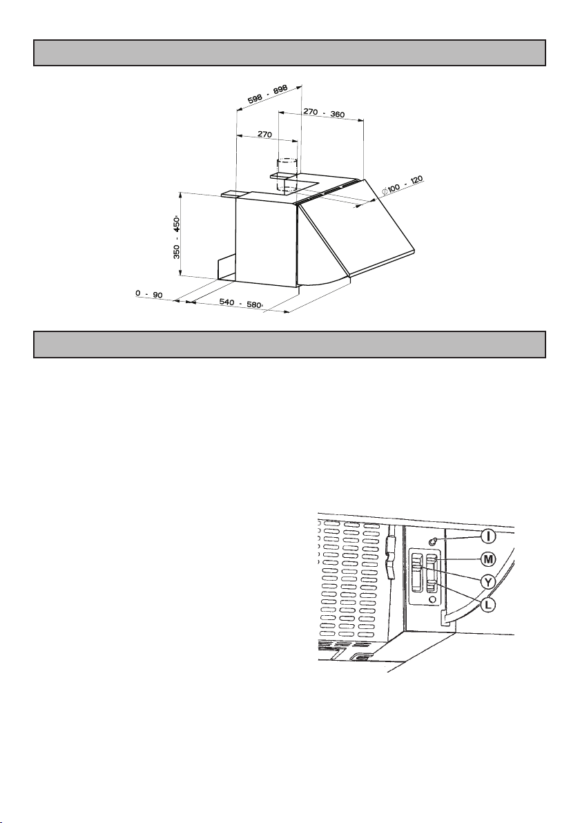
The Controls
I. Automatic Microswitch
The microswitch overrides the controls, and switches
off the hood when the visor is closed. When the visor is
opened the hood will resume the function of previoussetting.
M. Fan ON/OFF control
Y. Fan Speed Control
Position 1 - Low
Position 2 - Normal
Position 3 - Boost
L. Light ON/OFF control
4
Page 5
To operated
The appliance can be installed to recirculate or extract
contaminated air. The cooker hood is more effective when
used in the extraction mode.
Recirculation
In the recirculation mode contaminated air is passed
through the charcoal lter to be puried and recirculated
into the kitchen.
Extraction
In the extraction mode contaminated air enters the cooker
hood, passes through the grease lter and out through
the ducting into the atmosphere.
When the ducting position is selected the char-
coal lter is not required.
Never do ambé cooking under this cooker
hood.
Take extra care when frying and never leave
frying pans unattended during use as overheated fats and oils might catch re.
Do not leave naked ames under the cooker
hood.
Ensure heating areas on your hob are covered
with pots and pans when using the hob and
cooker hood simultaneously.
5
Page 6

MAINTENANCE AND CLEANING
Before carrying out any maintenance or clea-
ning isolate the cooker hood from the mains
supply.
The cooker hood must be kept clean, a build up
of grease or fat can be a re hazard.
External Cleaning
Wipe the cooker hood frequently with warm
soapy water using a mild detergent.
Always wear protective gloves when cleaning
the hood.
Never use scouring pads or abrasive cleaners.
Never use excessive amounts of water when
cleaning particularly around the control panel.
Synthetic Paper Grease Filter
The synthetic paper grease lter cannot be
cleaned.
It must not be washed.
To Replace the Synthetic Paper
Grease Filter
1. Open the metal grille pushing the knobs towards
the centre while pulling downwards..
4. Remove the wire clips and remove the lters.
Handle the wire clips with care and keep away
from children as they have sharp points.
6
Page 7

Charcoal Filter
0
1
2
3
The charcoal lter cannot be cleaned.
The lter should be replaced at least every
three months or more frequently if the hood
is used more than three hours per day.
To Remove/Replace the Charcoal
Filter
1. Open the metal grille pushing the knobs towards
the centre while pulling downwards.
2. support the lter with one hand, remove the round
disk through the centre of the charcoal lter and
rotate it till the lter will come away.
3. Replace by reversing the operation.
Changing the Light Bulb
If a lamp fails to function check that the bulb is
screwed into the holder.
If bulb failure has occurred then it should be
replaced with a 220-240V 40W clear
cylindrical shape bulb with a small E14 screw
thread.
Charcoal lters, grease lters and light
bulbs can be obtained from your local
Service Force Centre
This appliance can be a re hazard if the grease
and charcoal lters are not cleaned and replaced as recommended.
7
Page 8

SOMETHING NOT WORKING
If, having followed these instructions carefully, your cooker hood fails to work properly please carry out
the following checks.
Symptom
The cooker hood will not start
The cooker hood is not working effectively
The cooker hood has switched off during opera-
tion
If after all these checks, the problem persists,
contact your local Service Force Centre,
quoting the model and serial number.
Please note that it will be necessary to
provide proof of purchase for any
in-guarantee service calls.
SERVICE AND SPARE PARTS
Solution
• Check the hood is connected to the electricity supply.
• Check that the fan speed control is set to 1, 2 or 3.
• The fan speed is set high enough for the task.
• The grease lter is clean.
• The kitchen is adequately vented to allow the entry
of fresh air.
• If set up for recirculation, check that the charcoal
lter is still effective.
• If set up for extraction, check that the ducting and
outlets are not blocked.
• The safety cut-out device has been tripped.
• Turn off the hob and then wait for the device to re-
set.
In-guarantee customers should ensure
that the above checks have been made as
the engineer will make a charge if the fault
is not a mechanical or electrical
breakdown.
If you require an engineer or wish to purchase spare parts
contact your local Service Force Centre by
telephoning:
08705 929929
Your telephone call will be routed to your local
Service Force Centre. For further details please see the
accompanying customer care book.
For general assistance with your appliance or for information on Zanussi products please contact our Customer
Services Department.
Customer Services Department
Major Appliances
Zanussi
Addington Way
Luton
Bedfordshire
LU4 9QQ
Tel: 08705 727 727 *
* calls to this number may be recorded for training pur-
poses.
8
Page 9

GUARANTEE CONDITIONS
We Zanussi, undertake that if within 12 months of the date of the purchase this Zanussi built-in appliance or any part
thereof is proved to be defective by reason only of faulty workmanship or materials, the company will, at our option
repair or replace the same FREE OF ANY CHARGE for labour, materials or carriage on condition that:
• The appliance has been correctly installed and used only on the electrical supply stated on the rating plate.
• The appliance has been used for normal domestic purposes only, and in accordance with the manufacturer’s ope-
rating and maintenance instructions.
• The appliance has not been serviced, maintained, repaired, taken apart or tampered with by any person not authorised by us.
• All service work under this guarantee must be undertaken by Zanussi Service Force Centre.
• Any appliance or defective part replaced shall become the property of this company.
Home visits are made between 8.30am and 5.30pm Monday to Friday. Visits may be available outside these hours
in which case a premium will be charged.
EXCLUSIONS
This Guarantee does not cover:
• Damage or calls resulting from transportation, improper use or neglect, the replacement of any lilght bulbs or removable parts of glass or plastic.
• Costs incurred for calls to put right appliances improperly installed or calls to appliances outside the United Kingdom.
• Appliances found to be in use within a commercial environment, plus those which are the subject of rental agreements.
• Products of Zanussi manufacture which are not marked by Zanussi.
This guarantee is in addition to your statutory and legal rights.
ZANUSSI EUROPEAN GUARANTEE
If you should move to another country within Europe then your guarantee moves with you to your new home subject
to the following qualications:
• The guarantee starts from the date you rst purchased your product.
• The guarantee is for the same period and to the same extent for labour and parts as exists in the new country of
use for this brand or range of products.
• This guarantee relates to you and cannot be transferred to another user.
• Your new home is within the European Community (EC) or European Free Trade Area.
• The product is installed and used in accordance with our instructions and is only used domestically, i.e. a normal
household.
Before you move please contact your nearest Customer Care Centre, listed below, to give them details of your
new home. They will then ensure that the local Service Organisation is aware of your move and able to look
after you and your appliances.
France Senlis +33 (0)3 44 62 22 22
Germany Nurnberg +49 (0)911 323 2600
Italy Pordenone +39 (0)1678 47053
Sweden Stockholm +46 (0)20 78 77 50
UK Luton +44 (0)8705 727 727
9
Page 10

INSTALLATION INSTRUCTIONS
It is dangerous to alter the specications or attempt to modify this product in any way.
Technical Information
DIMENSIONS HEIGHT: 350mm
WIDTH: 598mm
DEPTH: 540mm
WEIGHT GROSS: 10,1 kg
NET: 8,9 kg
ELECTRICAL SUPPLY: Voltage (50Hz) 220-240 V
POWER CONSUMPTION: 180W
FAN MOTOR: 100W
LAMP: 80W
SUITABLE FOR INSTALLATION
ABOVE: ELECTRIC HOB: 7KW (max)
GAS HOB: 10KW (max)
SLOT-IN GAS COOKER 13.5KW (max)
SLOT-IN ELECTRIC COOKER 12.4KW (max)
Note: CE Marking certies that this appliance complies with the requirements laid
down in EEC directive 89:336. (Electromagnetic compatibility) and subsequent
modications and Low Voltage directive 72/23/E.
ELECTRICAL CONNECTIONS
This appliance must be earthed
Electrical Requirements
Any permanent electrical installation must
comply with the latest I.E.E. Regulations and
local Electricity Board regulations. For your own
safety this should be undertaken by a qualied
electrician e.g. your local Electricity Board, or a
contractor who is on the roll of the National
Inspection Council for Electrical Installation
Contracting (NICEIC).
Electrical Connection
Before connecting to the mains supply ensure
that the mains voltage corresponds to the
voltage on the rating plate inside the cooker
hood.
This appliance is tted with a 3 core mains
cable and must be permanently connected to
the electricity supply via a double-pole switch
having 3mm minimum contact gap on each
pole. A Switched Fuse Connection Unit to
BS1363 Part 4, tted with a 3 Amp fuse, is a
recommended mains supply connection
accessory to ensure compliance with the Safety
Requirements applicable to xed wiring
instructions.
This appliance conforms to BS 800: 1988 and
EEC Directive No. 78 308 regarding
suppression of radio and television
interference.
10
Page 11

INSTALLING THE COOKER HOOD
Please ensure that when the appliance is
installed it is easily accessible to an
engineer in the event of a breakdown.
All installations must comply with the local
authorities requirements for the discharge of
exhaust air.
Incorrect installation may affect the safety of this
cooker hood.
Installation Requirements
Before installation check the wall to which the
cooker hood is to be tted for electric cables,
water pipes or gas.
If it is necessary to x the hood to a hollow
construction plaster or partition board
structure then it should be sufciently
reinforced to be quite rigid in the area of the
cooker hood mounting brackets, and the
appropriate rawl plugs used for this type of
xing (not supplied).
Ducting
The ducting must be re retardant 100mm (4ins)
in diameter and the length should be no
more than:
3 metres with one 90° bend
2 metres with two 90° bends
Bends of more than 90° will reduce the
efciency of the hood and reduce the airow.
11
Page 12

The clereance height between the inferior part of
the cooker hood and the hob must be 650 mm (
some models can be tted at a lower height from
the hob, please refer to the installation paragraph).
Unpacking
The ttings supplied to install this cooker
hood can be found with the instruction book
inside the packaging.
The xing of the frontal panel to the visor:
1 Pull out the metal visor and, at the same time, unlock
the lever on the left side of the hood.
2 Use the cardboard template when drilling the front
panel. Fix the panel to the visor using the screws not
supplied.
Wall tting
The cooker hood is tted to the wall using the
keyhole slots in the back of the hood.
1 Hood depth can vary from 275 to 360 mm.
2 Regulate the Vx screws when adjusting the brackets
to the right depth.
3 When adjusting the lower part of the hood to the
requested depth it is necessary to loose the screws
of the metal distance piece and to move it as much
as necessary.
4 Use the specic cardboard template when drilling
the holes into the wall. Put the dowels into the holes
and x the two metal brackets using the four screws
not supplied together with other accessories.
5 Use the specic cardboard template when drillig the
side closets.
When the hood is used in ducting version it is necessary to
remove the grid from the air outlet.
6 Hang the hood on the metal brackets.
7 Put back the visor again paying attention that the
runners are put correctly into the proper places. Adjust
the visor sliding by means of the two screws.
8 Regulating the Vy screws it is possible to align the
hood height compared to the closets.
9 When necessary adjust again the hood depth.
10 Place the safety squares above the xing brackets.
11 Mark the midpoint of the holes.
12 Drill the wall and x the safety squares together with
screws and dowels (supplied).
12
Page 13

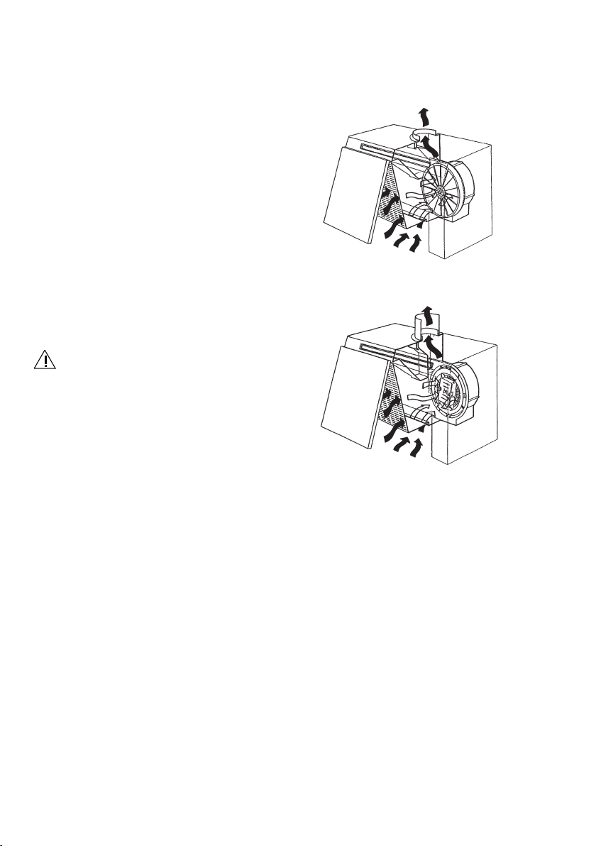
Venting
The hood is more effective when used in the
extraction setting (ducted to the outside).
Venting kits may be purchased through your
retailer or DIY store, and must be ducted to
an outside vent of 100mm (4”) minimum.
The ducting used must be manufactured from
re retardant material which should conform to
the relevant British Standard or DIN4102-B1.
When the hood is ducted externally the
charcoal lter must be removed and the
slider control must be in the ducting position.
To Fit the Ducting
When installing the ducted version, connect the hood to
the chimney using either a exible or rigid pipe ø120 mm,
the choice of which is left to the installer.
1 Fix the pipe in position using sufcient pipe clamps
(not supplied).
2 Remove any activated charcoal lters.
Recirculation
Ø 100
The charcoal lter must be
tted for recirculation and the slider control
must be in the recirculation position.
Fitting the Cooker Hood to the Wall
1 Make sure that the hood body has been completely
xed.
2 Make sure that hood is equipped with charcoal
lters.
13
Page 14

The symbol on the product or on its packaging indicates that this product may not be treated as household waste. Instead
it shall be handed over to the applicable collection point for the recycling of electrical and electronic equipment. By ensuring this
product is disposed of correctly, you will help prevent potential negative consequences for the environment and human health,
which could otherwise be caused by inappropriate waste handling of this product. For more detailed information about recycling
of this product, please contact your local city ofce, your household waste disposal service or the shop where you purchased the
product.
14
Page 15

In the event of your appliance requiring service, or if you wish
to purchase spare parts please contact your local Service
Force Centre by telephoning:
08705 929929
Your telephone call will be automatically routed to the Service
Force centre covering your post code area.
For the address of your local Service Force Centre and further
information about Service Force, please visit the website at
www
.serviceforce.co.uk
Before calling out an engineer, please ensure you read the
details under the heading Something not working.
When you contact the Service Force Centre you will need to
give the following details:
1. Your name, address and post code
2. Your telephone number
3. Clear and concise details of the fault
4. The model and serial number (found on the rating plate)
5. The purchase date
Please note that a valid purchase receipt or guarantee
documentation is required for in-guarantee service calls.
For Customer Service in Ireland please contact us at the
address below:
Zanussi
Electrolux Group (Irl) Ltd
Long Mile Road
Dublin 12
Republic of Ireland
Tel: + 353 (0)1 4090751
Email: service.eid@electrolux.ie
Customer Care
Department
For general enquiries concerning your Zanussi appliance or for
further information on Zanussi products please contact our
Customer Care Department by letter or telephone at the
address below or visit our website at www
.zanussi.co.uk
Service and Spare Parts
Customer Services Department
Major Appliances
Zanussi
Addington Way
Luton
Bedfordshire
LU4 9QQ
Tel: 08705 727 727 *
* calls to this number may be recorded for training
purposes.
15
Page 16

U kan toebehoren, verbruiksprodukten en onderdelen bestellen via onze
webwinkel op:
www.zanussi.be
Vous pouvez commander des accessoires, consommables et pièces détachées
via notre magasin online sur:
www.zanussi.be
Voor het on-line bestellen van accessoires, consumables en onderdelen gaat
u naar de ’webwinkel’ op:
www.zanussi.nl
436005225_01 - 101130
www.zanussi.com
 Loading...