

Page 1

ZES 2226 ZESW 2226
ZESN 2226 ZESX 2226
GB Installation and operating
instructions
4 - 9 Built-in control panel
D Einbau- und
Bedienungsanleitung
10 - 15 Einbauschaltkasten
DK Indbygnings- og
brugsvejledning
16 - 21 Betjeningspanel
NL Montage- en
Gebruiksvoorschrift
22 - 27 Inbouwschakelkast
F Instruction de montage
et d’utilisation
28 - 33 Boîtier de commande à encastrer
P Painel de comandos
encastrável
34 - 39
HR Upute za montiranje
i rukovanje
52 - 57 Ugradiva prekidaèka kutija
H Beszerlési- és kezelési
utasítás
58 −63 Beépíhetõ kapcsolószekrény
SLO Navodilo za vgradnjo in
uporabo
64 − 69 Vgradna kontrolna plo¹èa
CZ Návod k instalaci a pou¾iti
70 −75 Vcstavìný ovládaci panel
PL Instrukcja monta¿u i
obs³ugi
76 −81 Panel sterowniczy
do p³yt do gotowania
pod zabudowê
S Bruksanvisning
82 - 86 Vredpanel
FIN Asennus- ja käyttöohje
Sisäänrakennettu
40 - 45 kytkentäpaneeli
RO Instructiuni de montare
si mod de întrebuintare
46 - 51 Panou de comutare îngropat
NInstallajon-og
Bruksanvisning
88 - 92 Betjeningspanel
Page 2
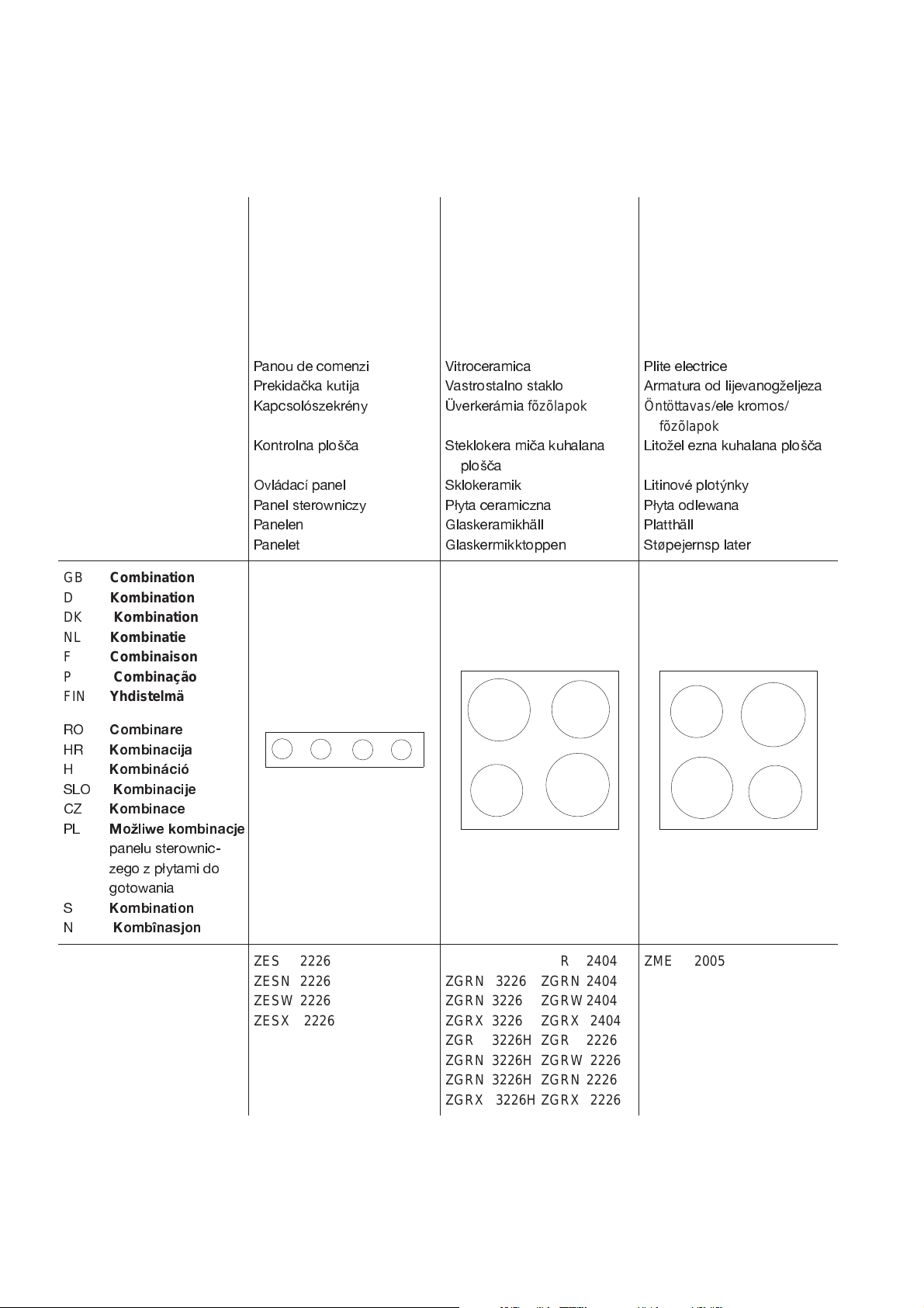
Control panel
Schaltkasten
Betjeningspanel
Schakelkast
Boîti er de commutation
Painel de comandos
Kytkentäpaneeli
Glass-ceramic
Glaskeramik
Glaskeramik
Glaskeramische kookplaat
Vitrocéramique
Placa vitrocerâmica
Keraaminen taso
Cast trough
Gussmulde
Støbt kogeplade
Gietyzeren kookplaat
Plaques en fonte
Placa eléctrica
Keittotaso
GB Combination
D Kombination
DK Kombination
NL Kombinatie
F Combinaison
P Combinação
FIN Yhdistelmä
RO
Combinare
HR
Kombinacija
H
Kombináció
SLO
CZ
PL
S
N
Kombinacije
Kombinace
Mo¾liwe kombinacje
panelu sterownic
zego z p³ytami do
gotowania
Kombination
Kombînasjon
Panou de comenzi
Prekidaèka kutija
Kapcsolószekrény
Kontrolna plo¹èa
Ovládací panel
Panel sterowniczy
Panelen
Panelet
Vitroceramica
Vastrostalno staklo
Üverkerámia
Steklokera mièa kuhalana
plo¹èa
Sklokeramik
P³yta ceramiczna
Glaskeramikhäll
Glaskermikktoppen
fõzõlapok
Plite electrice
Armatura od lijevanog¾eljeza
Öntöttavas
fõzõlapok
Lito¾el ezna kuhalana plo¹èa
Litinové plotýnky
P³yta odlewana
Platthäll
Støpejernsp later
/ele kromos/
ZES 2226
ZESN 2226
ZESW 2226
ZESX 2226
ZGR 3226 ZGR 2404
ZGRN 3226 ZGRN 2404
ZGRN 3226 ZGRW2404
ZGRX 3226 ZGRX 2404
ZGR 3226H ZGR 2226
ZGRN 3226H ZGRW 2226
ZGRN 3226H ZGRN 2226
ZGRX 3226H ZGRX 2226
ZME 2005VD
2
Page 3

GB Dear Customer!
R Stimate client!
Since the nameplate on your appliance will
no longer be accessible after instellation, we are
providing a duplicate nameplate herewith.
Please attache the plate in your users manual.
D Sehr geehrter Kunde!
Da das Typenschild auf Ihrem Gerät mit
allenwichtigen Datenund Angabennachdem Einbau
nichtmehr zugänglichist, habenwir Ihnenein zweites
Typenschild beigelegt.
Bitte Typenschild in die Gebrauchsanleitung kleben.
DK Kære kunde!
Typeskiltet som er placeret på pladens underside, vil efter indbygning i bordplade være svært
tilgængeligt.VibederDem derforpåsætte detmedfølgende ekstra typeskilt i brugsanvisningen.
NL Geachte klant!
Omdat het typeplaatje op uwapparaat, met
alle belangrijke gegevens na de montage niet meer
te zien is, hebben wij een tweede typeplaatje bijgevoegd.
F Cher client!
Vu que la plaque signalétique de votre appareilavec sesdonnéeset caractéristiquesimportantes n’est plus accessible après l’encastrement, nous
vous en avons joint une seconde.Nous vous prions
de coller cette plaque signalétique dans votre mode
d’emploi.
P Estimado Cliente
Deoarece eticheta cu datele si caracteristicile aparatuluiDvs. numai este accesibiladupa montare,v-ampusladispozitieoadouaeticheta.
Va rugam sa lipiti aceasta eticheta în modul Dvs. de
întrebuintare.
HR ©tovani kupèe !
Natpis (ploèica) s va¾nim tehnièkim podacima i oznakom modela sprave, æe poslije montiranja
sprave biti nepristupaèni, te Vam radi toga prila¾emo
duplikat.
Molimo Vas, da ovaj duplikat nalijepite u Va¹im uputama za rukovanje urejiajem.
H Kedves Vásárlónk!
Mivel a beszerelés után a legfontosabb információkat tartalmazó adattábla már nem lesz
hozzáférhetõ a készüléken, mellékeltünk egy második adattáblát. Kérjük ragassza be ezt az adattáblát
a használati utasításba.
SLO Spoštovani kupec!
Ker tablica z oznakami na¹va em aparatu
po vgradnji v kuhinjsko omarico ne bo veè dostopna,
smo vam prilo¾ili dodatno tablico z oznakami, ki jo
prilepite v knji¾ico z navodili za uporabo.
CZ Vá¾ený zákazníku !
Proto¾e typový ¹títek Va¹eho pøístroje se
v¹emi dùle-¾itými daty a údaji nebude po vestavìní
pøístroje pøístupný, pøikládáme druhý typový ¹títek.
Prosíme Vás, vlepte tento typový ¹títek do návodu k
pou¾ití.
Uma vez que a placa sinalética do seu
aparelho, com informações e caracterísicas importantes, ficou inacessível depois de o aparelho
estar encastrado, nós damos-Ihe uma segunda. Pedimos-Ihe que cole esta placa sinalética nas suas
instruções de serviço.
FIN Hyvä asiakas!
Koska tämän laitteen tyyppikilpi kaikkine
tärkeine tietoineen on asentamisen jälkeen piilossa,
pyydämme Teitä liittämään tämän tyyppikilven oheisen kaksoiskappaleen käyttöohjeeseen.
PL
Na tabliczce znamionowej podano parametry urz±dzenia. Po ustawieniu urz±dzenia w zabudowie tabliczka bêdzie niewidoczna, dlatego
dol±czono drug± tabliczkê znamionow± któr± nale¿y
wkleiæ do instrukcji obs³ugi.
3
Page 4

GB Installation
The installation and connection may only be carried out by a licensed specialist. The statutory
regulations and the connection requirements of the
local electricity supply company must be complied
with. Moreover, the legislation concerning electrical
installationsstipulates that theuser ofan applianceis
also responsible that it isinstalled and used correctly
in accordance with these instructions.
Since only correct installation can ensure protection
against accidental contact with live parts, appliances
must only be used after they have been correctly
installed.
Dimensions
The appliance must only be installed in a totally
enclosed kitchen unit. The rear end of this enclosure
mayalsobeformedbythewalloftheroomagainst
which the unit is built. The upper face is formed by
eitherthework-top orthe sinkunit,whilethe sidewalls
of the kitchen unit and an intermediate base form the
ends around and underneath the appliance.
Dimensionsof the openingin thefront wallof theunit:
(height x width) 69 x 350 mm.
These various faces produce an enclosure for installing the appliance with the following minimum measurements:
(height x width x depth) 80 x 396 x 200 mm
Caution: To ensure that the control panel fits tightly
into theopening cut outfor it, thematerial formingthe
frontwall into whichthe controlpanel isto beinstalled
must be at least 16 mm thick.
When thisopening is cut, itis essential toensurethat
the dimensionsof the opening arestrictly adhered to.
The installation of the glass ceramic hot plate or the
cast iron hot plate into the work surface takes place
according to the separate instructionns.
1. Openthe lidof theterminalbox. Leadtheconnection cable to the terminal box and connectaccording to theconnection diagram on theinstrument
lid.
2. Ensure that all connections between the cooking
station and the flushmounted circuit box are correctly made (see the markings on the lid)!
4
Page 5

3. Attention: A second rating plate must be affixed
in acleally visible position on the inside of the
pieceof furnitureunderneath. Therecessed plate
must be dismountable.
Electrical connection / feedline
1. The connection can be made directly or via a
socket installed on-site (ensure cable strainrelief
fitted). For direct connections:Allow about 1.2 m
cable length from the wall.
2. The mains connection cable used must be of the
type H05VV-F or of a higher rating.
3. The mains connection is to be carried out so that
threre isthe possibility of separatingallpoles with
a minimum contact opening of 3 mm.
4. The yellow/green earthed conductor flex coming
from thehob is integratedin the 21-poleplug.The
earthed conductor should be checked to ensure
it is connected correctly.
5. The connector boxes attached to the hob wiring
is now inserted in the 21-pole socket board located at the rear of the control panel.
6. The controlpanel is insertedin the openingin the
front wall of the kitchen unit.
Attention: The cable must not touch the cast hot
plate.
Only when the operations described above have
been completed can the fuses be replaced in the
mains supply and the control panel or hob used.
The appliance is only protected against accidental
contact when it has been fully installed in the kitchen
unit. The fuses must only be replaced or the main
switch turned on when installation is complete. The
appliance must be fitted and secured in accordance
with these installation and operating instructions.
We must stress the fact that we accept no liability for
any direct or indirect damage or injury resulting from
incorrect connection or from installation work carried
out by unauthorised persons.
When carrying out service work, the equipment
must be disconnected from the mains supply.
5
Page 6

Dismounting
Beforethe controlpanel isremoved,the mainssupply
must be disconnected, then:
- the bottom of the enclosure (intermediate base)
must be removed or the plate at the front of the
control panel unscrewed.
- the retaining springs (B) on each side of the control
panel must be depressed and the box slid forward.
Operation
1. Cooking area front left-heat control knob
2-circuit
2. Cooking area rear left-heat control knob
3. Cooking area rear right-heat control knob
2-circuit
4. Cooking area front right-heat control knob
work-top
intermediate
base
control panel
0
1
0
1
2
3
4
6
5
1
0
1
0
1
9
2
8
3
7
4
6
5
2
0
1
0
1
9
8
7
9
2
8
3
7
4
6
5
34
0
1
0
1
9
2
8
3
7
4
6
5
2-circuit regulator
The switches (1) and (3) are additional for 2-circuit
cooking plates.
Theswitchescanonlybeturnedtotheright.
With the combination of the panel-mounting control
panelandaglass ceramiccookingfieldequipped with
2-circuit heater, this feedback switches can be used
to switch on either one or both heating circuits of the
2-circuit cooking zones.
Connectionof the secondheating circuitis performed
by turning theadjustment togglebeyond theendstop
(perceptibleengagement).The secondheating circuit
is switched off by turning back the toggle to its zero
position.
For feedback control of the entire cooking field, the
same adjustment scale applies as for the quick cooking field.
Thisdescription isonlyvalidforglassceramiccooking
fields with 2-circuit heaters.
0
1
1
2
3
4
0
9
8
7
6
5
Ifthe controlpaneliscoupled toa castcooking trough
or a glass ceramic cooking field without 2-circuit
heater,theendstop switchofthe feedbackswitch has
no function. Thesame description then appliesas for
the «normal» control switch, except that the switch
does only be turned on to the limit stop.
6
Page 7

Heat control knobs
The heat control knobs allow fully adjustable regulation ofthe heatoutput. Theycanbe turned bothto the
right and to the left. Each control knob has two stops
which are intended to clearly mark the division in the
range of cooking temperatures. The operating range
from «0» to the first stop (position 5) is the temperature range designed for keeping food warm and for
continuing a cooking process that has already been
commenced. The range from position «5» to the
second stop (position 10 - maximum) is for heating
food up or for starting the cooking process.
It is advisable to set the knob to position «10» when
the cooking process is initially started. In the case of
foodstuffs that require a cooking time of up to 20
minutes, the knob can be turnedbackto «0» and the
cooking process completed without any electricity
being used after the initial cooking process. In the
case of foodstuffs that require a longer cooking time,
the cooking process can be completed at a setting in
the1-5range.
0
1
1
2
3
4
0
9
8
7
6
5
7
Page 8

The correct pans
It is important that pans with regular flat bottoms are
used (standard pans designed for electric hotplates
or ceramic pots and pans) since pans with uneven
bottoms do not absorb sufficient heat from the cookingarea andthus leadto unnecessarilylong cooking
times. For the same reason, pans should not be too
small, but should have bottoms of the same size as
thecookingarea.
It should be ensured that the pan is always placed
exactly on the cooking area as shown by the markings.
This is the right kind of pan. It has a strong machinefaced bottom, absorbsthe heat well fromthe cooking
areaandprotectsitfromoverheating. Itis alittlelarger
than the cooking area and therefore shields it from
anything that might boil over.
This pan is too small and causesaconsiderable loss
of heat. In addition, if anything boils over it burns on
the cooking area and is very difficult to remove.
Wet pans should never be used and lids coated with
condensed steamshould never beplaced on unused
cooking areas. Dampness and steam cause calcium
deposits to build up with time.
Pots and pans with thin or buckled bottoms should
never be used sincethese cause the cooking area to
overheat. Ideally pans should have strong machinefaced bottoms.
8
Page 9

Model and rating plate
The nameplate giving details of the model electrical
rating is located on the cover of the heater. When a
fault is reported, it is essential that the information
(model designationand serial number)shown on this
plate is quoted.
Thiswillsave anyadditionalexpense thatmightotherwise be incurred by our service engineer having to
make several trips.
Serial number
Affix 2nd nameplate
Prod-nr:
max. 6.7kW 400V2-3N/230 V/230V3 ~ 50 Hz
EZ 13
+
S
Serie
ZES 2226
Model designation
This appliance conforms with
EC-Directive Nummer
73/23/EEC, 89/336/EEC, 93/68/EEC
9
Page 10

315 2460 00 / 10.97
 Loading...