

Zanotti un0◦ Workshop Manual
Zer0° 120
#0WSMZ120
Workshop Manual
®

Z120 Workshop Manual
Print Order Code# 0WSMZ120 Rev. 2
Release Dates and Revisions
2/27/2018 Released
5/30/2018 Rev. 2 – Figures, Specification, Sub-section 7.1

The maintenance information in this manual cover unit models: Z120 ALL VARIANTS
For further information, refer to: Z120 Series Parts list
- WEB
0MD
0MDL178 C
The information in this manual is provided to assist Authorized Zanotti Dealerships and
Recover Refrigerant
Zanotti Spa recognizes the need to limit the
allowing refrigerants to escape into the atmosphere. Zanotti defers to the local jurisdiction and
promotes only approved procedures when handling refrigerant.
We strictly adhere to a policy that promotes the recovery and limits the loss of refrigerant into the
atmosphere.
In
refrigerants and
the certification of technicians. For additional information refer to the
L176 C - NSA PARAMETERS TABLE
- NSA - Zer0 series - Maintenance Schedule
Service Centers.
This manual is published for informational purposes only and the information so provided should not be considered
as all-inclusive or covering all contingencies. If further information is required, Zanotti Corporation should be
consulted.
Sale of product shown in this manual is subject to Zanotti terms and conditions including, but not limited to, the
Zanotti Warranty. Such terms and conditions are available upon request. Zanotti warranty will not apply to any
Equipment that has been altered outside the manufacturer’s plants.
potential harm to the ozone layer that can result from
addition, service personnel must be aware of Federal regulations concerning the use of
E.P.A.
DISCLAIMER:
Manufacturer is not responsible and will not be held liable in contract or in tort (including negligence)
or any special, indirect or consequential damages, including injury or damage caused to vehicles,
contents or persons, resulting from the installation of any Zanotti product or its mechanical failure.
FEEDBACK FORM
Manual Code Number
Section and page #
Your name
Company Name
Phone Number
Email
*Corrections or Suggestions*
We appreciate your suggestions and comments for our Manuals. Please follow
the form below to allow us to make any necessary corrections or suggestions.
Return to:
Zanotti Transblock USA Corp.
OR
Email to:
T-gostynski@zanotti.com
1810 underwood Blvd
Delran, NJ 08028
Attn: Service Department

Contents
3.2.3 Defrost and Heat ..................................... 16
3.2.4 Refrigeration Symbol Table ..................... 17
Table of Contents
Contents .................................................................... 4
Table of Figures ......................................................... 6
GENERAL SATEFY NOTICES ........................................ 1
SPECIFIC WARNING AND CAUTION STATEMENTS .... 3
SPECIFICATIONS ........................................................ 5
Z120 MAINTENANCE SCHEDULE ............................... 6
SECTION 1 – Unit Description .................................... 7
1.1 CONDENSING SECTION .................................... 7
1.1.1 Condenser coil .......................................... 7
1.1.2 Filter drier ................................................. 7
1.1.3 Compressor .............................................. 7
1.1.4 Receiver .................................................... 7
1.1.5 High-pressure switch ................................ 7
1.1.6 CPR valve .................................................. 7
1.1.7 Electric standby operation ....................... 7
3.2.5 Defrost system ........................................ 18
3.2.6 Manual defrost ........................................ 18
3.2.7 Defrost relay............................................ 18
3.2.8 Defrost solenoid valve (Hot Gas Solenoid Valve)
......................................................................... 18
3.2.9 Condenser Inlet valve.............................. 18
3.3 CONTROL SYSTEM .......................................... 19
3.3.1 Description .............................................. 19
3.3.2 Microprocessor module (CPU Board) ..... 19
3.3.3 In-cab controller ............................... 19
3.4 START UP ........................................................ 21
3.4.1 Starting ............................................. 21
3.4.3 Weekly Pre-trip Inspection ..................... 21
3.4.4 After Start Inspection .............................. 22
3.4.5 Loading Procedure .................................. 22
3.4.6 Post Load Procedure ............................... 22
1.1.8 DC Motor .................................................. 7
1.1.9 AC Motor .................................................. 7
1.2 EVAPORATOR SECTION ................................... 9
1.2.1 Thermostatic expansion valve .................. 9
1.2.2 Evaporator coil ......................................... 9
1.2.3 Defrost coil ............................................... 9
1.2.4 Evaporator drain tube heaters ................. 9
1.2.4 Hot gas solenoid valve .............................. 9
1.3 MICROPROCESSOR AND CONTROL BOX ........ 10
1.3.1 Microprocessor board ............................ 10
1.3.2 Control box ............................................. 11
SECTION 2 – Unit Identification............................... 12
2.1 DECIPHERING THE MODEL CODE .................. 12
2.2 DECIPHERING THE SERIAL NUMBER .............. 13
SECTION 3 - Operation ............................................ 14
3.1 SAFETY DEVICES............................................. 14
3.4.7 Weekly Post Trip Checks ......................... 22
3.5 ALARM MANAGEMENT .................................. 22
3.5.1 Accessing alarm messages ...................... 22
3.5.2 Reset alarms ............................................ 22
3.5.3Alarms list ................................................ 23
3.6 MICROPROCESSOR PARAMETERS .................. 24
3.6.1 To enter a Set Point ................................ 24
3.6.2 Parameter programming ........................ 24
3.6.3 Common Parameters .............................. 24
3.6.4 Service Alarm Management .................... 26
SECTION 4-System Maintenance ............................. 27
4.1 GENERAL CATEGORIES ................................... 27
4.1.1 Electrical .................................................. 27
4.1.2 Refrigeration ........................................... 27
4.1.3 Structural ................................................ 27
4.2 INSTALLING THE MANIFOLD GAUGE SET ....... 27
3.2 REFRIGERATION CIRCUIT ............................... 14
3.2.1 Cooling .................................................... 14
3.2.2 Null ......................................................... 15
4.2.1 Manifold Gauge Components ................. 28
4.2.2 Preparing Manifold Gauges for use ........ 28
4.2.3 Connecting Manifold Gauges .................. 28

4.2.4 Removing the Manifold Gauge Set ........ 28
4.17.3 Condenser Coil ...................................... 42
4.3 REMOVING THE REFRIGERANT CHARGE ....... 28
4.4 REFRIGERANT LEAK CHECKING ...................... 29
4.5
EVACUATION AND DEHYDRAYION ................ 29
4.5.1 Preparation ............................................. 29
4.5.2 Procedure for evacuation and dehydrating
the system ....................................................... 29
4.6 CHARGING THE REFRIGERATION SYSTEM ..... 30
4.7 LOW SIDE PUMP DOWN ................................ 31
4.8
CHECKING THE REFRIGERANT CHARGE ......... 31
4.9 CHECKING AND REPLACING FILTER-DRIER .... 32
4.9.1 Checking Filter-Drier................................... 32
4.9.2 Replacing the Filter-Drier ........................... 32
4.10 PRESSURE SWITCHES ................................... 33
4.10.1 Removing switches ............................... 33
4.10.2 Testing Pressure Switch........................ 33
4.11 COMPRESSOR .......................................... 34
4.11.1 Removal ................................................ 34
4.11.2 Installation ............................................ 34
4.17.4 Condensor Mounting Bolts ................... 42
4.18
ELECTRICAL MAINTENANCE ..................... 43
4.18.1 In-cab controller .................................... 43
4.18.2 Unit is not working in electric mode 43
4.18.3 Electric standby circuits ........................ 43
4.18.4 DC Motor Maintenance ........................ 44
SECTION 5 - Diagnosis .............................................. 45
5.1 TROUBLESHOOTING TOPICS .......................... 45
5.2 TROUBLESHOOTING BY SYMPTOM ................ 47
5.3 TROUBLESHOOTING BY ALARM CODE ........... 53
SECTION 6 – Temperature and Pressure ................. 56
6.1 VAPOR TEMP/PRESSURE RELATIONSHIP ....... 56
6.2 PRESSURES AT 100⁰F AMBIENT ..................... 57
Section 7 – Parameter Values .................................. 57
7.1 Parameter Issues ............................................ 57
Common Parameter issues .............................. 57
7.2 SETTING VALUES single-temperature - R404a/R134a -
without stand-by option ...................................... 58
4.11.3 System Compressor and Oil ................. 34
4.11.4 Adding extra oil to the system ............. 34
4.11.5 Checking the oil level............................ 34
4.12 HOT GAS & CONDENSER SOLENOID VALVE &
COILS ................................................................... 35
4.12.1 Diagnosis of solenoid coils ................... 35
4.12.3 Diagnosis of solenoid valves ................. 35
4.12.3 Replacing solenoid coil ......................... 36
4.12.4 Replacing Valve Internal Parts .............. 37
4.13 BRAZING PROCEDURES ............................... 37
4.14 THERMOSTATIC EXPANSION VALVE ............ 38
4.14.1 Expansion Valve Superheat Check &
Adjustment ...................................................... 39
4.14.2 Diagnosing Expansion valves ................ 40
4.14.3 Replacing expansion valve ................... 40
4.15 ADJUSTING THE CPR VALVE ........................ 40
4.16 TESTING DEFROST SYSTEM ......................... 41
7.3 SETTING VALUES single-temperature - R404a/R134a -
with stand-by option ............................................ 59
SECTION 8 - Wiring diagrams ................................... 60
8.1 Z1001N REV.2 ................................................. 61
8.2 Z1006 REV.2 ................................................... 62
8.3 Z1006N REV.3 ................................................. 63
8.4 WIRING DIAGRAM KEY ................................... 64
4.17 STRUCTURAL MAINTENANCE ...................... 42
4.17.1 Unit Inspection ..................................... 42
4.17.2 Evaporator Coil ..................................... 42

Table of Figures
Figure 1 - Z120 Condensing Section Components ....................................................................................................... 8
Figure 2 - Z120 Evaporator Section Components ........................................................................................................ 9
Figure 3- CPU Board Component Diagram ................................................................................................................. 10
Figure 4 - Control Box Components ........................................................................................................................... 11
Figure 5 - Unit Identification Tag ................................................................................................................................ 12
Figure 6 - Z120 Cool Mode Refrigeration Diagram .................................................................................................... 15
Figure 7 - Z120 Heat/Defrost Mode Refrigeration Diagram ...................................................................................... 16
Figure 8 - Solenoid Valve ............................................................................................................................................ 18
Figure 9 - In-cab Controller ........................................................................................................................................ 19
Figure 10- In-cab controller LCD screen definitions ................................................................................................... 20
Figure 11 - Refrigeration Gauge Components............................................................................................................ 28
Figure 12- Vacuum Pump Connections ...................................................................................................................... 29
Figure 13- Refrigeration Gauge Connection ............................................................................................................... 30
Figure 14 - Sight Glass Inspection .............................................................................................................................. 32
Figure 15 - Filter / Drier .............................................................................................................................................. 32
Figure 16 - Nitrogen Test Setup ................................................................................................................................. 33
Figure 17 - Compressor Oil Sight Glass ...................................................................................................................... 34
Figure 18 - Solenoid Valve Components .................................................................................................................... 36
Figure 19 - Brazing Example ....................................................................................................................................... 37
Figure 20 - Expansion Valve Components .................................................................................................................. 38
Figure 21- TXV location Drawing ................................................................................................................................ 38
Figure 22 - Equalizer line and Evaporator Outlet ....................................................................................................... 39
Figure 23 - Superheat Test Connections .................................................................................................................... 39
Figure 24 - Correct TXV Bulb placement .................................................................................................................... 40
Figure 25 - CPR Valve Components ............................................................................................................................ 40
Figure 26 - CPR valve adjustment ............................................................................................................................... 41
Figure 27 - Z120 Evaporator Section .......................................................................................................................... 42
Figure 28 - Z120 Condensing Section ......................................................................................................................... 42

1
GENERAL SATEFY NOTICES
WARNING: Use ONLY Polyol Ester based refrigeration compressor oil in units. DO NOT mix Polyol Ester and standard
synthetic compressor oils. Keep Polyol Ester compressor oil in tightly sealed containers. If Polyol Ester oil becomes
contaminated with moisture or standard oils, dispose of properly—DO NOT USE!
WARNING: When servicing Zanotti units, use only those service tools certified for and dedicated to refrigerant and
Polyol Ester compressor oils. Residual non-HFC refrigerants or oils will contaminate R- 404A and R-134A systems.
1. Always wear goggles or safety glasses. Refrigerant liquid, refrigeration oil, and battery acid can
permanently damage the eyes (see First Aid under Refrigeration Oil).
2. Never operate the unit with the compressor discharge valve closed.
3. Keep your hands, clothing and tools clear of the fans and belts when the unit is running. This
should also be considered when opening and closing the compressor service valves.
4. Make sure manifold gauge hoses are in good condition. Never let them come in contact with a
belt, fan motor pulley, or any hot surface.
5. Never apply heat to a sealed refrigeration system.
6. Fluorocarbon refrigerants including r134a and r404a, in the presence of an open flame or
electrical short, produce PHOSGENE. A toxic gas that are severe respiratory irritants capable of
causing death.
7. Make sure all mounting bolts are tight and are of correct length for their application.
8. Use extreme caution when drilling holes in the unit. The holes may weaken structural
components, and holes drilled into electrical wiring can cause fire or explosion.
9. Use caution when working around exposed coil fins. The fins can cause painful lacerations.
10. Use caution when working with a refrigerant or refrigeration system in any closed or confined
area with a limited air supply (for example, a vehicle box or garage). Refrigerant tends to displace
air and can cause oxygen depletion resulting in suffocation and possible death.
11. When performing any check of the system make sure the unit is turned off and the battery power
supply is disconnected.
12. Be sure unit is turned off before working on motors, controllers, solenoid valves and electrical
components. Problems with the system should be diagnosed, and any necessary repairs
performed, by qualified service personnel only.
13. Do not bypass any electrical safety devices, for instance bridging an overload or using any sort of
jumper wires.
14. Do not wear any electrically conducting materials. I.E. jewelry, rings, watches, necklaces, etc.
15. Secure any loose objects on self. Such as hair, jacket laces, shoe laces, etc...
Refrigerant
Although fluorocarbon refrigerants are classified as safe refrigerants, certain precautions must be observed when
handling them or servicing a unit in which they are used. When exposed to the atmosphere from the liquid state,
fluorocarbon refrigerants evaporate rapidly, freezing anything they contact.
In the event of frost bite, the objectives of First Aid is to protect the frozen area from further injury, to warm the
affected area rapidly and to maintain respiration.

2
Refrigeration oil
Avoid refrigeration oil contact with the eyes. Avoid prolonged or repeated contact of refrigeration oil with skin or
clothing. Wash thoroughly after handling refrigeration oil to prevent irritation. In case of eye contact, immediately
flush with plenty of water for at least 15 minutes. Wash skin with soap and water. CONTACT A PHYSICIAN.
Electrical Hazards (High voltage)
When servicing or repairing a refrigeration unit, the possibility of serious or even fatal injury from electrical shock
exists. Extreme care must be used when working with an operating refrigeration unit. Lethal voltage potentials can
exist on connections in the high voltage tray of the control box.
Precautions:
1. When working on high voltage circuits on the refrigeration unit, do not make any rapid moves.
If a tool drops, do not grab for it. People do not touch high voltage wires on purpose! It occurs
from an unplanned movement or action.
2. Use tools with insulated handles that are in good condition. Never hold metal tools in your
hand if exposed, energized conductors are within reach.
3. Treat all wires and connections as high voltage until a meter and wiring diagram show
otherwise.
4. Never work alone on high voltage circuits on the refrigeration unit, another person should
always be standing by in the event of an accident to shut off the refrigeration unit and to aid
a victim.
5. Have electrically insulated gloves, cable cutters and safety glasses available in the immediate
vicinity in the event of an accident. IMMEDIATE action must be initiated after a person has
received an electrical shock. Obtain immediate medical assistance if available. The source of
shock must be immediately removed by either shutting down the power or removing the
victim from the source. If it is not possible to shut off the power, the wire should be cut with
either an insulated instrument (e.g., a wooden handled axe or cable cutters with heavy
insulated handles) or by a rescuer wearing electrically insulated gloves and safety glasses.
Whichever method is used. Do not look at the wire while it is being cut. The ensuing flash can
cause burns and blindness. If the victim has to be removed from a live circuit, pull the victim
off with a non-conductive material. Use the victim’s coat, a rope, wood, or loop your belt
around the victim’s leg or arm and pull the victim off. DO NOT TOUCH the victim. You can
receive a shock from current flowing through the victim’s body. After separating the victim
from power source, check immediately for the presence of a pulse and respiration. If a pulse
is not present, start CPR (Cardio Pulmonary Resuscitation) and call for emergency medical
assistance.
3
Electrical Hazards (Low Voltage)
der without a pressure regulator. Cylinder
Compressor failure will occur if inert gas brazing procedures are not used
1. Low voltage Control circuits used in the refrigeration unit are low voltage (12/24 volts dc). This voltage
potential is not considered dangerous, but the large amount of current available (over 30 amperes) can cause severe
burns if shorted or grounded. Do not wear jewelry, watches or rings. These items can short out electrical circuits
and cause severe burns to the wearer.
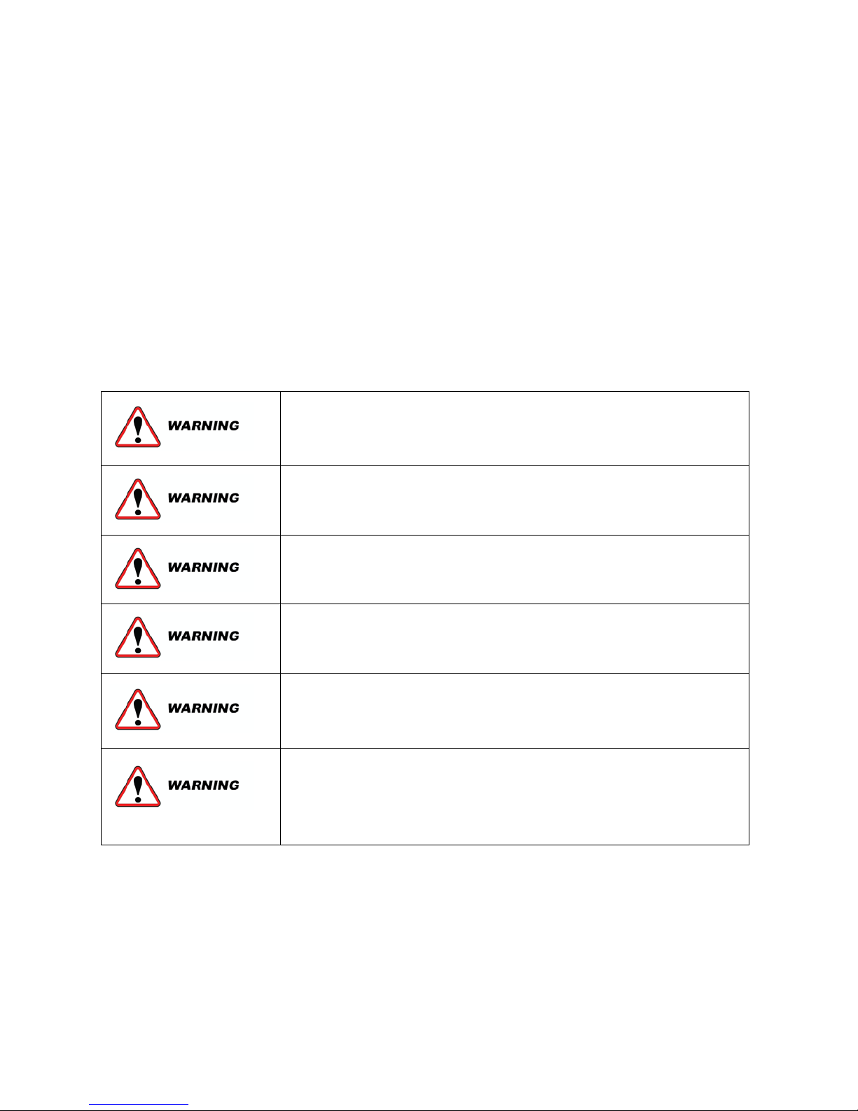
SPECIFIC WARNING AND CAUTION STATEMENTS
To help identify the hazards on the unit and explain the level of awareness each one carries, an explanation is given:
WARNING: means an immediate hazard that will result in severe personally injury or death
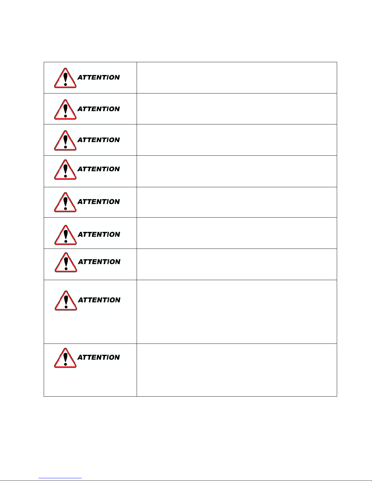
ATTENTION: means to warn against potential hazard or unsafe practice, which could result in or personal injury,
product or property damage.
The statements listed below are applicable to the refrigeration unit and appear elsewhere in the manual. These
recommended precautions must be understood and applied during operation and maintenance of the equipment.
Beware of unannounced starting of the unit. The unit may cycle the fans
and compressor unexpectedly as control requirements dictate. Press OFF
key on the cab command.
Beware of V-belt and belt-driven components as the unit may start
automatically.
Ensure power to the unit is OFF and vehicle engine is OFF and negative
battery cable is connected before replacing parts.
Slowly open the plug on the suction and discharge valves of the new
compressor to vent the nitrogen holding charge
Do not use a nitrogen cylin
pressure is approximately 2350 psigg (160 bars). Do not use oxygen in or
near a refrigerant system as an explosion may occur.
on units with R404A/R134A and POE oil.
4
If starting unit for the first time after installation the compressor
If starting unit for the first time after installation or starting after
Compressor failure will occur if inert gas brazing procedures are not
To prevent trapping liquid refrigerant in the manifold gauge set be sure
When working with refrigerant use safety glasses and gloves to avoid
Refrigerant R404a is a blend. Charging as a vapor will change the
Observe proper polarity when installing battery. Negative battery
Under no circumstances should a technician electrically probe the
harness attaches. Microprocessor components operate at different
voltage levels and at extremely low current levels. Improper use of
, continuity testers, etc. could permanently
Most electronic components are susceptible to damage caused by
touch. This is especially true of the integrated circuits found on the
pressure regulating valve will need to be reset.
adding/removing an optional feature or if Owners operating parameters
have changed, the Configuration will need to be reset.
used on units with R404A/R134A and POE oil.
set is brought to suction pressure before disconnecting
burns. Hoses and copper tubing can be hot when unit is running.
properties of the refrigerant. Only liquid charging is acceptable.
terminal must be grounded.
processor at any point, other than at the connector terminals where the
voltmeters, jumper wires
damage the processor.
electrical static discharge (ESD). In certain cases, the human body can
have enough static electricity to cause damage to the components by
microprocessor. Use proper board handling techniques.
5
SPECIFICATIONS
Oil Charge
(oz)
Compressor
1750
13.5
Polyol Ester 32
Open
(psig)
Closed
(psig)
HP switch (r404a)
Closed
450 ±10
377 ±10
HP switch (r134a)
Closed
330 ±10
255 ±10
Component
Value (psig)
CPR Valve
29
Type
Charge (lbs)
R134a
2.0
R404a
2.0
Component
Value (ft-lb)
Condenser Cover 7
Mounting bolts
44-60
Compressor shaft
seal plate (M6)
Compressor
Crankcase (M8)
22.15
Full load
(amp)
Z120
12V
554
4.5 @ 13V
Z120
24V
574
2.3 @ 26V
Full load
(amp)
Z120
12V
484
5.9 @ 13V
Z120
24V
602
4.0 @ 26V
Full load
(amp)
Hot Gas
12V
10
1.7 @ 14V
Condenser
12V
7.2
0.9 @ 26V
Capacitor
Voltage
µF
CS (start)
120 VAC
145÷
175
CM (run)
120 VAC
80
Fuse
Desc.
12V
Amps
24V
Amps
FSS
12
12
F6
30
20
F8
30
20
FR
Standby supply
5 5 FB
Battery supply
5
5
FS
Transformer fuse
2 2 FGS
General
100
100
Motor
Voltage
Amps
AC
120
13.2
DC
12V
65
Component
Value (ft-lb)
AC Belt
5
DC Belt
6
Compressor data
Condenser fan motor
Condenser
Fan
Voltage
Airflow
(CFM)
current
Component RPM
Oil Type
Defrost data
Type: hot gas or air defrost
Initiation: adjustable, 1 to 9 hours Termination timer
through parameter ”dF”
Pressure switch data
Component Normal
Compressor Regulating Valve (CPR)
The CPR valve can only be set during defrost
Refrigerant charge
Refrigerant charge values are only an approximation.
Evaporator fan motor
Evaporator
Fan
Voltage
Solenoid Coils (hot gas, condenser)
Solenoid Coil Voltage Ohms
Capacitors
Fuses
Airflow
(CFM)
current
current
Torque value
13.25
Belt Tension
Defrost solenoid
Condenser Fa n
Evaporator Fan
Motor Data
6
Z120 MAINTENANCE SCHEDULE
Working hours
100
1000
2000
3000
4000
5000
6000
7000
X1000
Break-in
x
Maintenance A
x x x x x x x
Maintenance B
x x x
Maintenance E
x x x x x x x
x
• Clean condenser and evaporator
Check tension of belts
• Replace brushes of D.C motor
condenser fans
• Check voltage and current absorption of
Check and clean electric connections
• Check and clean expansion valve orifice
Maintenance Schedule (Alarm Signal SEE or SEr)
Instructions:
Perform Maintenance A every 1000 hours Perform Maintenance B every 2000 hours
Perform Maintenance E every 1000 hours (standby only)
Maintenance A
Maintenance B
Maintenance E
Every year
• Check oil level on compressor
• Check defrost cycle & drain tubes
• Check battery and its terminals
• Check refrigerant charge
• Check and clean electric connections
•
• Replace belts
• Check operation of evaporator and
transformer, rectifier, electric motors
•
• Replace filter drier
• Replace refrigerant gas & check superheat
• Replace compressor oil

7
SECTION 1 – Unit Description
Zanotti Z120 refrigeration systems are designed for
low and medium temperature applications on vans
and small-sized trucks with one compartment. There
are several basic models:
• 134a systems and 404a systems
• Road only and Road with standby
equipped
The system consists of two separate assemblies: the
condenser and the evaporator.
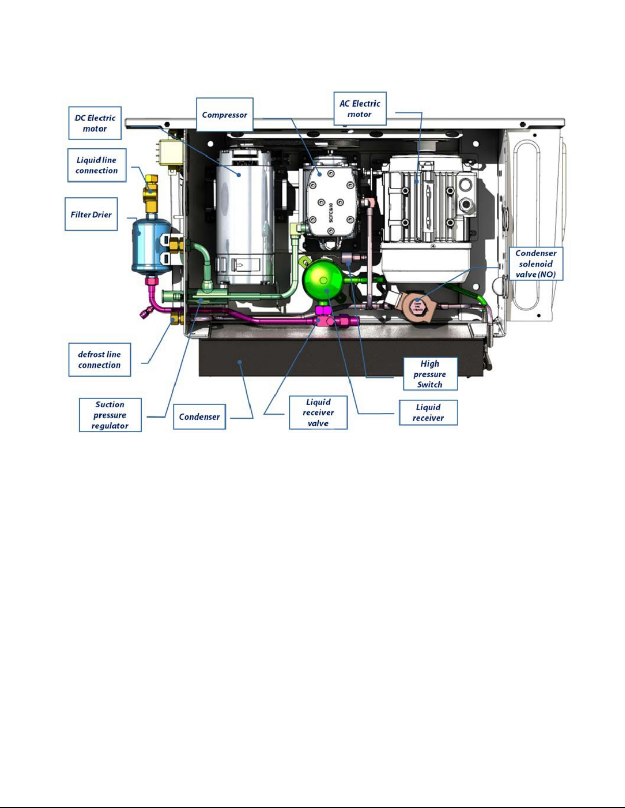
1.1 CONDENSING SECTION
The condenser has a unique design that allows it to be
mounted horizontally on the roof, or on the front of
the vehicle box.
1.1.1 Condenser coil
The condenser is mini-tube type and acts as heat
exchanger in which the compressed refrigerant gas is
condensed into a liquid and lowered in temperature.
A fan mounted in the condensing section provides air
movement on the condenser.
1.1.2 Filter drier
The drier is a cylindrical shell containing a drying
agent and screen. It’s installed in the liquid line and
functions to keep the system clean and remove
moisture from the refrigerant.
1.1.3 Compressor
The compressor is a reciprocating two cylinder. This
compressor is mounted in the center of the
condensing unit and is driven by belt from either the
12/24 vdc motor or the vac electric standby motor
Compressor operation is controlled by the
thermostat, which energizes the motor during road
operation or starts the electric motor and energizes
the ac motor on electric standby operation. The
refrigeration system is protected by a high-pressure
cut-out switch and a low-pressure cut-out switch.
When plugged into standby power, road operation is
automatically locked out. If the vehicle engine is
turned on while the power cord is still plugged into a
power receptacle, the unit will show an alarm signal;
the 12/24 vdc motor cannot be started until the power
cord is unplugged from the unit as the selection of road
operation or standby operation is automatic.
1.1.4 Receiver
Liquid refrigerant from the condenser is delivered to the
receiver. The receiver serves as a liquid reservoir when
there are surges due to load changes in the system; as a
storage space when pumping down the system and as a
liquid seal against the entrance of refrigerant gas into the
liquid line.
1.1.5 High-pressure switch
The High-Pressure Cut-out Switch is a pressure sensitive
switch. If the discharge pressure rises above the switch’s
opening pressure, the switch opens the circuit to stop the
unit. When the discharge pressure falls below the switch’s
closing pressure, the switch closes to restart the unit.
1.1.6 CPR valve
The compressor pressure regulation valve (CPR valve) is
installed on the suction line to regulate the suction
pressure entering the compressor. The CPR valve protects
the compressor and is set to limit the maximum suction
pressure. For CPR settings refer to section 4.16
1.1.7 Electric standby operation
During electric standby operation, the thermostat controls
the operation of the unit by energizing and de-energizing
the power relay and the electric relays. The thermostat
places the unit in cool by energizing the Power relay and
the electric relays.
1.1.8 DC Motor
The DC motor drives the compressor in Road Mode. When
the vehicle is turned on and the In-Cab controller is turned
on the KMC relay is activated through the CPU Board
1.1.9 AC Motor
The AC motor drives the compressor in Stand by Mode.
When the vehicle is turned off and the electric stand by
plug is plugged in the CPU board will activate the K1
Contactor energizing the electric motor
8
Figure 1 - Z120 Condensing Section Components
9
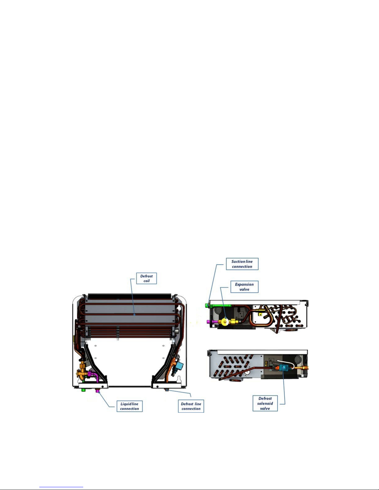
1.2 EVAPORATOR SECTION
The evaporator is mounted on the ceiling inside the
vehicle box. The evaporator assembly consists of an
evaporator fan, evaporator coil, and thermostatic
expansion valve, hot gas solenoid, temperature
probe.
1.2.1 Thermostatic expansion valve
The thermostatic expansion valve (TXV valve) is an
automatic device that controls the flow of liquid to
the evaporator according to changes in superheat of
the refrigerant leaving the evaporator. The thermal
expansion valve maintains a relatively constant
degree of superheat in the gas leaving the evaporator
regardless of suction pressure. Thus, the valve has a
dual function; automatic expansion control and
preventing liquid from returning to the compressor.
For TXV superheat settings see Section 4.14.1
1.2.2 Evaporator coil
The evaporator is of the tube and fin type. The
operation of the compressor maintains a reduced
pressure within the coil. At this reduced
pressure, the liquid refrigerant evaporates at a
temperature sufficiently low enough to absorb heat from
the air. Air movement over the evaporator is provided by
an electric fan.
1.2.3 Defrost coil
Coil lined under evaporator pan to defrost ice.
1.2.4 Evaporator drain tube heaters
Evaporator heaters are used to avoid drain tube blockage
because of ice accumulation inside the evaporator. Two
harnesses are located inside the drain tube. These resistive
wires melt the ice while the unit is in DEFROST mode.
1.2.4 Hot gas solenoid valve
The hot gas solenoid valve is normally closed and prevents
discharge gas from entering the evaporator. The valve
opens to allow hot gas refrigerant to be delivered from the
compressor to the evaporator during heat or defrost
modes.
Figure 2 - Z120 Evaporator Section Components
10
1.3 MICROPROCESSOR AND CONTROL BOX
Fuse
Desc
12V unit
Amps
24V unit
Amps
Defrost/heat
Condenser
Fan
Evaporator
Standby
supply
Battery
supply
The control circuits operate on 12V or 24V DC supplied
by the vehicle batteries for engine operation. On
standby operation, the power is rectified from an AC
transformer.
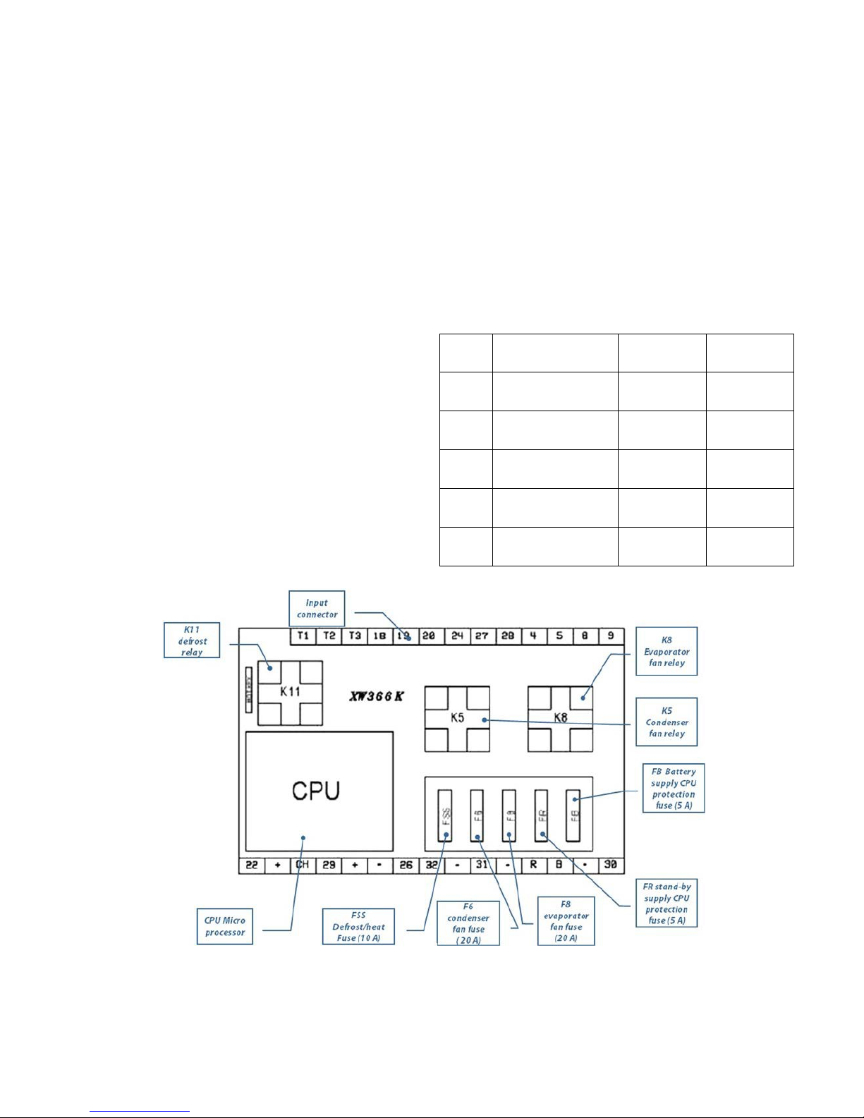
1.3.1 Microprocessor board
All Printed Circuit Boards manufactured by Zanotti can
be easily identified by the Part Number stamped on
them. Even though that all
P.C. boards have a similar layout, there are some
differences from one to another depending on the unit
model and which functions they carry out.
Microprocessor relays
The common relays are located on the P.C. Board.
When the Commutation Relays are energized the
electric power for the unit changes from Battery
Supply to Power Cord Supply.
Evaporator Fan Relay (K8)
When the Fan Relay is energized, battery voltage
energizes evaporator fan motors M8 – M9.
Condenser Fan Relay (K5)
When the Fan Relay is energized, battery voltage energizes
evaporator fan motors M5 – M6.
Defrost Relay (K11)
The Defrost Relay controls operation of the defrost cycle.
The Defrost Relay is energized when the In-Cab Controller
Defrost Switch is pressed or by the Defrost Timer. The
Defrost Relay will remain energized until the defrost cycle
is terminated by the CPU
Microprocessor Fuses
FSS
solenoids
F6
F8
Fan
FR
FB
10 10
20 20
20 20
5 5
5 5
Figure 3- CPU Board Component Diagram
11
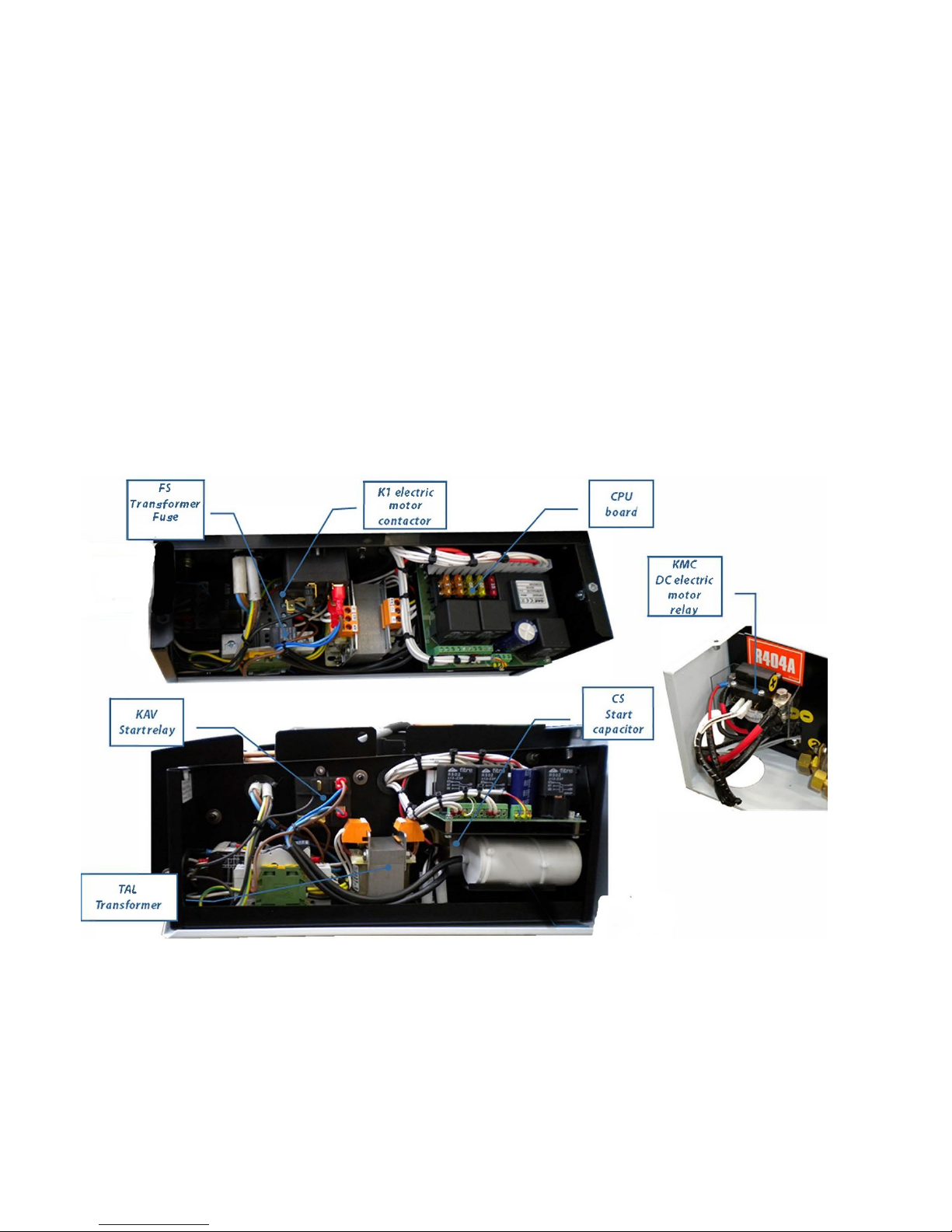
1.3.2 Control box
The standby relays are located into the control box.
DC electric motor relay (KMC)
When vehicle key is on, power is to the unit, and all
inputs to the CPU board are correct (pressure
switches, etc.) the KMC relay is activated to power
DC motor. KMC is considered a “power relay”
Electric Motor Contactor (K1)
When plugged in on electric standy it is powered by
the CPU board. K1 is considered a “power relay”
Start Relay (KAV)
Allows start capacitor to be powered during startup
When the Electric Standby Relay is energized it turns on
the AC Motor of the electric standby motor to drive the
compressor
FS transformer fuse
Two (2) Amp fuse
FGS – General protection fuse
100 Amp fuse. Location can be on battery harness.
CS Start Capacitor
Assists with starting of the AC electric motor
Figure 4 - Control Box Components
12
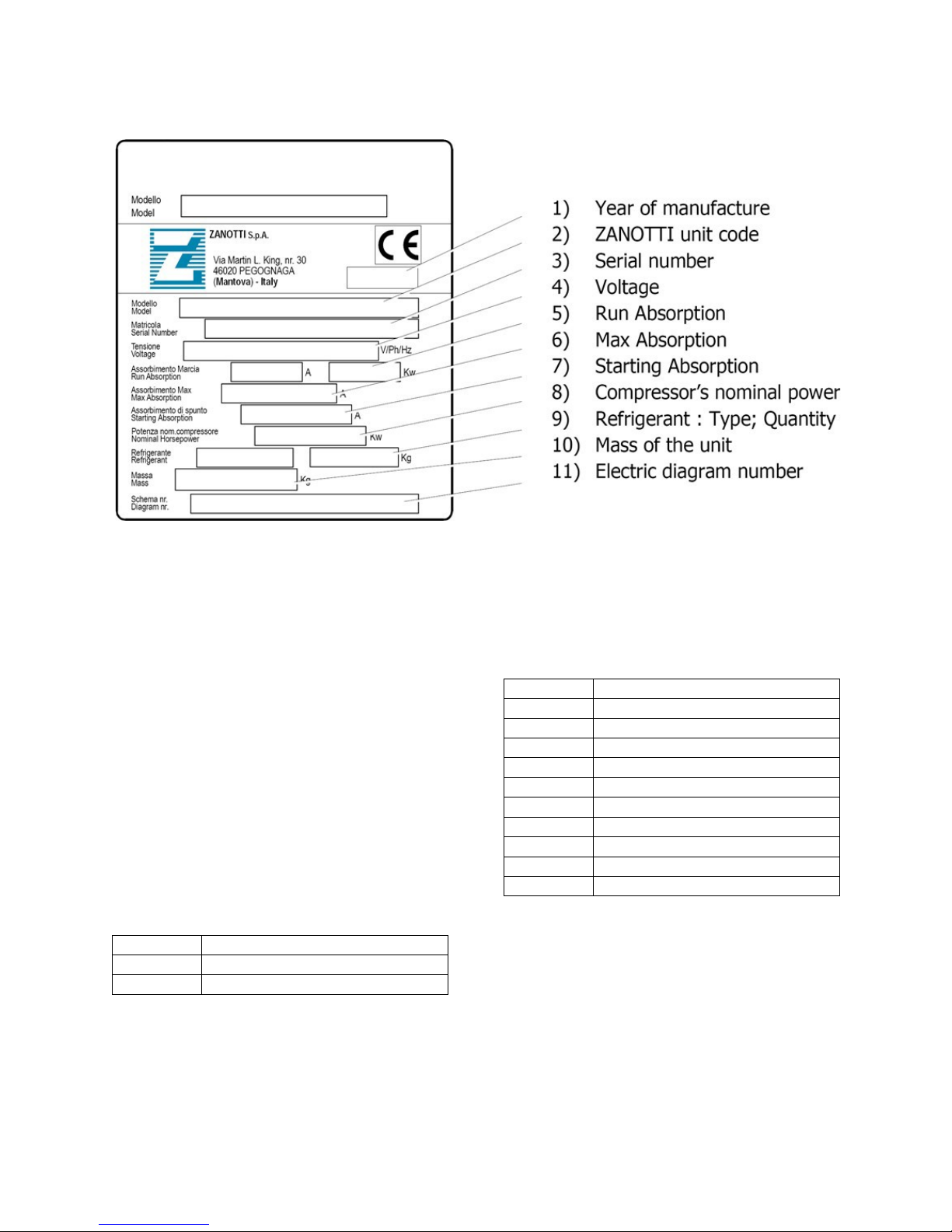
SECTION 2 – Unit Identification
Value
Definition
A
Road 12V
B Road/Standby 12V
C Road multitemp 12V
D Road/Standby multitemp 12V
E
Road 24V
F Road/Stand-by 24V
G Road multitemp 24V
H Road/Standby multitemp 24V
L Only standby 12V
M Only standby 24V
Value
Definition
B
Battery Drive
S Engine Compressor
Figure 5 - Unit Identification Tag
2.1 DECIPHERING THE MODEL CODE
The ten-digit model code can be broken down to
understand the unit range, drive type, supply version,
model variant and refrigerant.
Example: Z120BBE00E model code has ten digits
Character 1
Z = zer0° range unit
Character 2,3,4
120 = unit model
Character 5
B = Drive Type
Character 6
B = Supply Version Category
13
Character 7
Value
Definition
0
Only road
A
230/1/50
B
400/3/50
C
230/3/50
D
230/3/60
E
115/1/60
F
230/1/60
G
400/3/60
Value
Definition
E
R134a
F
R404a
B = Standby supply version
Character 8,9
00 = standard variant.
These numbers identify main versions and features of the units itself
Character 10
E = r134a refrigerant
2.2 DECIPHERING THE SERIAL NUMBER
Example: 1423134B
Each machine has a unique 8-character serial number with seven numbers and ending with a letter.
Character 1,2
14 = year of construction
Character 3,4
23 = week of production
Character 5,6,7
134 = progressive number
Character 8
B = identification letter for the modification from previous letter

14
SECTION 3 - Operation
Excess current on
fans
F6, F8 fuse
on CPU
NO
1.3.2
Excess
discharge press.
High-
switch (HP1)
YES Excess current
motor
FGS Road
NO
1.3.2
Excess current
heat mode
FSS Fuse on
board
NO
1.3.2
Excess current
motor
F1T in
NO
1.3.3
Low battery
voltage
Alarm Code
PAb
YES
3.5.3
Excess current
inputs
FB Fuse on
board
NO
1.3.2
Road & Standby
Supply
Alarm Code
YES
AC Motor Klixon
F1t
Yes
3.1 SAFETY DEVICES
The Zanotti Z120 machines are equipped with system
components to protect from damage caused by
unsafe operating conditions that automatically shut
down the unit when such conditions occur. This is
accomplished by the following fuses and safety
devices.
Unsafe Condition
Safety
Device
Auto
restart
Ref.
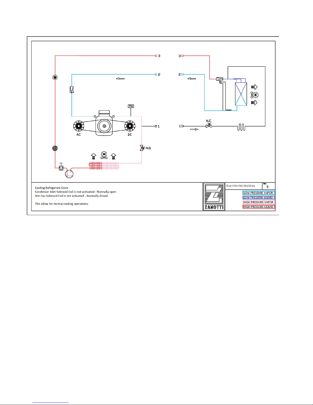
3.2.1 Cooling
When cooling, the unit operates as a vapor compression
refrigeration system. The main components of the system
are the reciprocating compressor, air-cooled condenser,
thermostatic expansion valve, direct expansion
evaporator, and hot gas solenoid (two-way).
The compressor raises the pressure and temperature of
the refrigerant and forces it into the condenser circuit. The
condenser fan circulates surrounding air over the outside
of the condenser. Heat transfer is thus established from
the refrigerant gas (inside the circuit) to the air ambient
(flowing over the circuit). The condenser is designed to
improve the transfer of heat. This removal of heat causes
the refrigerant to liquefy; liquid refrigerant flows from the
compressor
pressure
condenser to the receiver.
The refrigerant then flows through the filter- drier, where
draw on road dc
Supply Fuse
an absorbent keeps it dry and clean. The refrigerant then
flows through a sight glass with moisture indication.
draw in defrost or
electric
The liquid then flows to the thermostatic expansion valve
that regulates the flow rate of refrigerant in the evaporator
draw of the AC
control box
to obtain maximum use of the evaporator heat transfer
surface. The evaporator tubes have aluminum fins to
increase heat transfer; therefore, heat is removed from
the air circulated through the evaporator. This cold air is
circulated throughout the refrigerated compartment to
draw on PC board
electric
maintain the box at the desired temperature. The transfer
of heat from the air to the low temperature liquid
refrigerant causes the liquid to vaporize.
The vapor at low temperature and pressure enters the
3.2 REFRIGERATION CIRCUIT
evaporator coil and then enters the compressor pressure
regulating valve (CPR) that regulates refrigerant pressure
entering the compressor, where the cycle starts over.
The operation modes are Cool, Null, Defrost and Heat.
The machines cycle between Cool and Null to
maintain the box temperature at the set point.
The thermostat controls the operation of the unit by
energizing and de-energizing the Power Relays PR
(KMC or K1). When PR is energized it energizes the
evaporator fans, the condenser fans, and the motor
contactor.
15
Figure 6 - Z120 Cool Mode Refrigeration Diagram
3.2.2 Null
Null mode is when the unit is powered on but reached setpoint. At the time the unit is in null mode. No relays are
activated. The motors, fans, compressors, and solenoid are not activated. The thermostat energizes the power relay
(KMC or K1) at box temperatures higher than set point. The thermostat deenergizes the PR relay when it reaches the
set point. When PR is de-energized the unit does not operate and the unit is in Null mode.
16
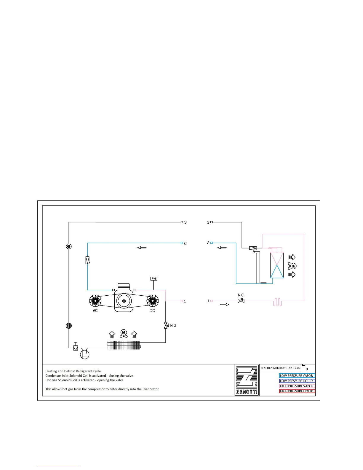
3.2.3 Defrost and Heat
Figure 7 - Z120 Heat/Defrost Mode Refrigeration Diagram
When low-pressure refrigerant vapor is compressed to a high-pressure the temperature rises and the mechanical
energy is transferred to the gas as it is being compressed. This energy is referred to as the “heat of compression”
and is used as the source of heat during the heating or defrost cycle.
When the microprocessor activates heating or defrost, the hot gas solenoid valve energizes, opening a port which
allows heated refrigerant vapor to flow directly to the evaporator coil. The microprocessor also activates the
condenser inlet solenoid valve, closing the flow of refrigerant to the condenser. Allowing all the hot gas to enter the
evaporator. The main difference between heating and defrosting is that when in heating mode the evaporator fans
continue to run thus circulating the air throughout the compartment to heat the product. When in defrost, the
evaporator fans stop, thus allowing the heated vapor to defrost any ice build-up on the coil.
The defrost cycle can be initiated any time the evaporator coil temperature is below 35°F. Defrost is initiated
automatically by the defrost timer, or manually by pressing the manual defrost switch. The defrost relay energizes
the hot gas solenoid valve (and the condenser solenoid valve on units equipped with the heat option) to route hot
refrigerant gas to the evaporator when PR is energized. The defrost relay also interrupts power to the evaporator
and condenser fans during defrost.
The defrost cycle will continue until the defrost interval has ended.
 Loading...