


ZKM 3118 KX
OPERATING AND
ASSEMBLY INSTRUCTIONS GB
for Ceramic Built-In Hobs

Dear customer GB
We thank you for choosing a ceramic hob of ZANKER.
Thus you chose quality, innovation and durability.
These operating and assembly instructions will allow
you to become acquainted with the appliance and to
do everything within its possibilities.
Contents
Unpacking and control . . . . . . . . . . . . . . . . . . . . . . . . . . . . . . . . . . . . . . . . . . . . . 11
Preparation for installation . . . . . . . . . . . . . . . . . . . . . . . . . . . . . . . . . . . . . . . . . . . 11
Fasteningaccording . . . . . . . . . . . . . . . . . . . . . . . . . . . . . . . . . . . . . . . . . . . . . . . . 11
Electrical connection . . . . . . . . . . . . . . . . . . . . . . . . . . . . . . . . . . . . . . . . . . . . . . 12
Important for the disassembly of the hob . . . . . . . . . . . . . . . . . . . . . . . . . . . . . . . . . . . . . 12
Before the first use . . . . . . . . . . . . . . . . . . . . . . . . . . . . . . . . . . . . . . . . . . . . . . . 13
Description of appliances . . . . . . . . . . . . . . . . . . . . . . . . . . . . . . . . . . . . . . . . . . . . 13
Cooking zones . . . . . . . . . . . . . . . . . . . . . . . . . . . . . . . . . . . . . . . . . . . . . . . . . . 14
Switching of the two-circuit zone . . . . . . . . . . . . . . . . . . . . . . . . . . . . . . . . . . . . . . . . . 14
Operating of the warm-keeping zone . . . . . . . . . . . . . . . . . . . . . . . . . . . . . . . . . . . . . . . 14
Residual Heat Indicator . . . . . . . . . . . . . . . . . . . . . . . . . . . . . . . . . . . . . . . . . . . . . . 14
Cooking equipment . . . . . . . . . . . . . . . . . . . . . . . . . . . . . . . . . . . . . . . . . . . . . . . 15
Maintenance . . . . . . . . . . . . . . . . . . . . . . . . . . . . . . . . . . . . . . . . . . . . . . . . . . . 16
Cleaning after each use . . . . . . . . . . . . . . . . . . . . . . . . . . . . . . . . . . . . . . . . . . . . . . 16
Stain removal . . . . . . . . . . . . . . . . . . . . . . . . . . . . . . . . . . . . . . . . . . . . . . . . . . . 16
Specification . . . . . . . . . . . . . . . . . . . . . . . . . . . . . . . . . . . . . . . . . . . . . . . . . . . 17
What to do in case of a defect? . . . . . . . . . . . . . . . . . . . . . . . . . . . . . . . . . . . . . . . . . 17
10
This appliance conforms
with EC-Directive
72/23/EEC, 89/336/EEC, 93/68/EEC
Seal
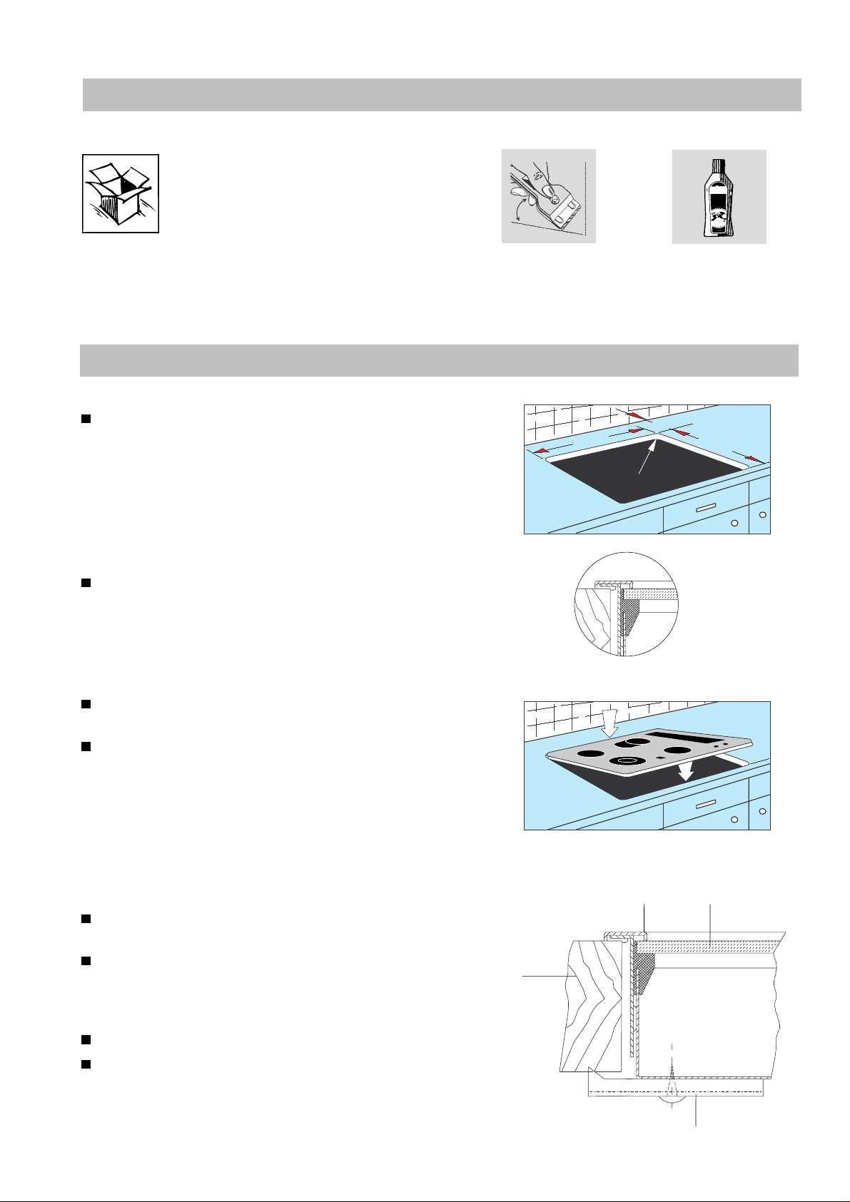
Unpacking and control
Please examine the appliance for any
damage sustained during transportation! If the appliance is damaged please
immediately inform the fo rwarding company before the appliance is connected. The packing material should be
disposed properly.
Preparation for installation
Cut out worktop to prescribed measurements or
templates (saw exactly along the scribing).
Check seal for perfect fit and overall cover.
Lower the ceramic hob into place and align correctly.
In terms of fire protection, the appliance conforms
to Type Y (IEC 335-2-6). Only appliances of this
type may be installed on one side of adjacent
upright furniture housings or walls.
780 ±1
50
500 ±1
R 24
1
2
Fastening according
Fasten bracket against the underside of the worktop.
Using a standard or Phillips screwdriver, tighten
the tension clamps evenly starting at the centre
and moving diagonally, until the built-in rim is tight
on the worktop.
Do not overtighten!
Do not use an electric or pneumatic screw driver
without an adjustable safety clutch! (pos. 1-
1.1Nm).
to Fig. 1
Fig.1
Ceramic
Worktop
Bracket
11
Electrical connection
The electrical connection of the ceramic
hob to the specially provided built-in
switch box and to the built-in range
should only be carried out by a trained
technician.
During assembly the switch box and the stove must
be idle.
Connect cable-plug with appropriate receptacle fixed
on range or controlbox.
Futhermore attention should be paid to the assembly
instructions for the built-in switch box or oven with
which the hob is connected!
Protection against accidental contact must be ensured by assembly.
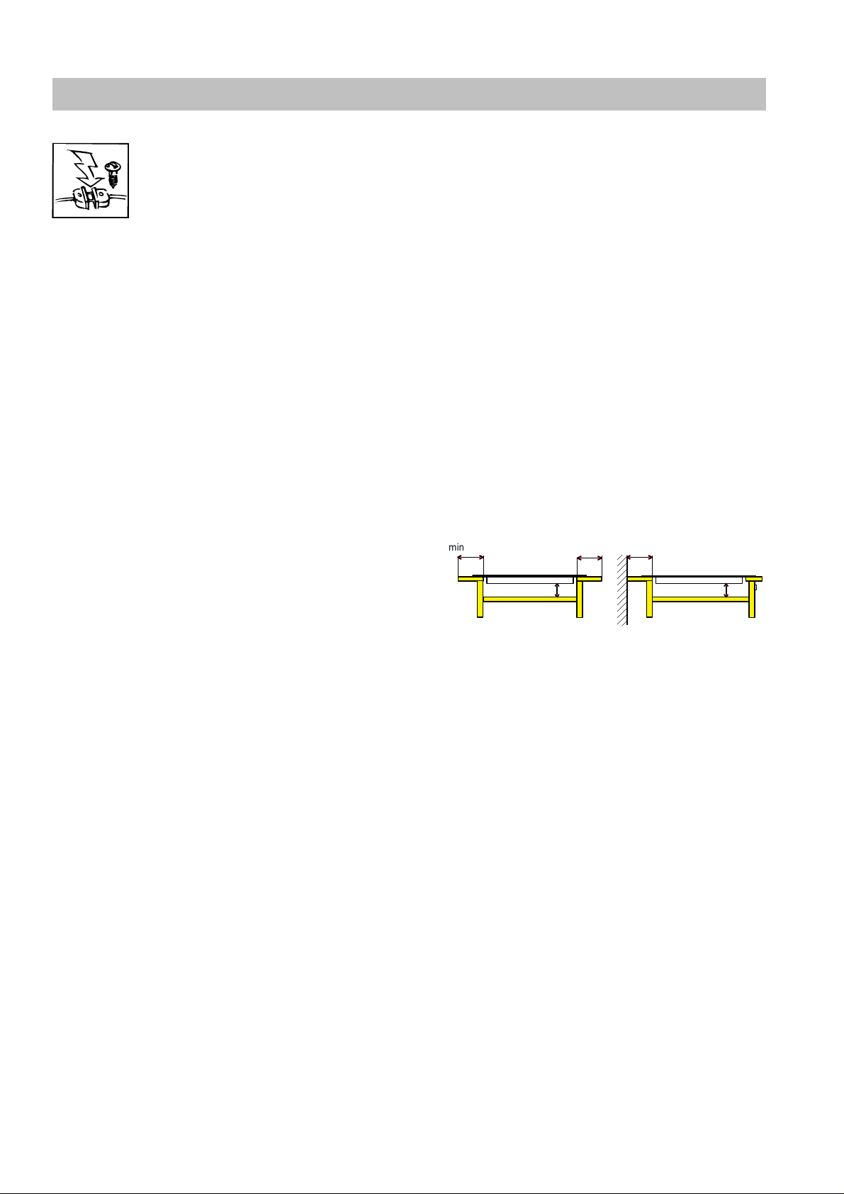
If the hob is operated from a switch box then it is
necessary to have an intermediate bottom to ensure
protection against accidental contact!
The distance between the underside of the hob and
the furniture beneath must be at least 20 mm.
Arrangements of hob - built - in oven/switch box may
be looked-up in a special table which is an appendix
to these instructions.
Before installation and operation of the appliance the
range of possibilities for combining the hob with the
oven /switch box is to be checked by referring to the
appropriate instructions for installation and operation.
Using other hobs than those of the ZANKERBrand excludes any liability.
If these regulations are not observed all given
approvals of test institutes are void.
min. 50 mm
20 mm
min. 50 mm
min. 50 mm
20 mm
Important for the disassembly of the hob
The supply of mains current to the appliance must be
cut off (for example by unscrewing the safety devices).
12
 Loading...