

Page 1
ZKM 3013
Gebrauchs- und Einbauanweisung D
Glaskeramik-Kochfelder
Operating and assembly instructions GB
Glass ceramic hobs
Notice d'utilisation et de montage F
Plans de cuisson vitrocéramique
Istruzioni per l'uso e per il montaggio I
Piani di cottura in vetroceramica
Gebruiksaanwijzing en inbouwinstructies NL
Keramisch kookplateau
Brugs- og installationsanvisning DK
Glaskeramiske kogeplader
Page 2
DEAR CUSTOMER
We congratulate you on choosing a ceramic hob of
Zanker. Thus you chose quality, innovation and durability.
These operating and assembly instructions will allow you
to become acquainted with the appliance and to do
everything within its possibilities.
10
Page 3
CONTENT
Unpacking and control ........................................... 12
Preparation for installation ..................................... 12
Electrical connection ............................................. 13
Before the first use ................................................ 14
Description of appliances ...................................... 14
Operating instructions ........................................... 14
Cooking equipment ............................................... 15
Maintenance ......................................................... 16
Technical data ....................................................... 17
What to do in case of a defect............................... 17
11
Page 4
UNPACKING AND CONTROL
Please examine the appliance for
any damage sustained during transportation! If the appliance is damaged please immediately inform the
forwarding company before the
appliance is connected. The packing material should be disposed
properly.
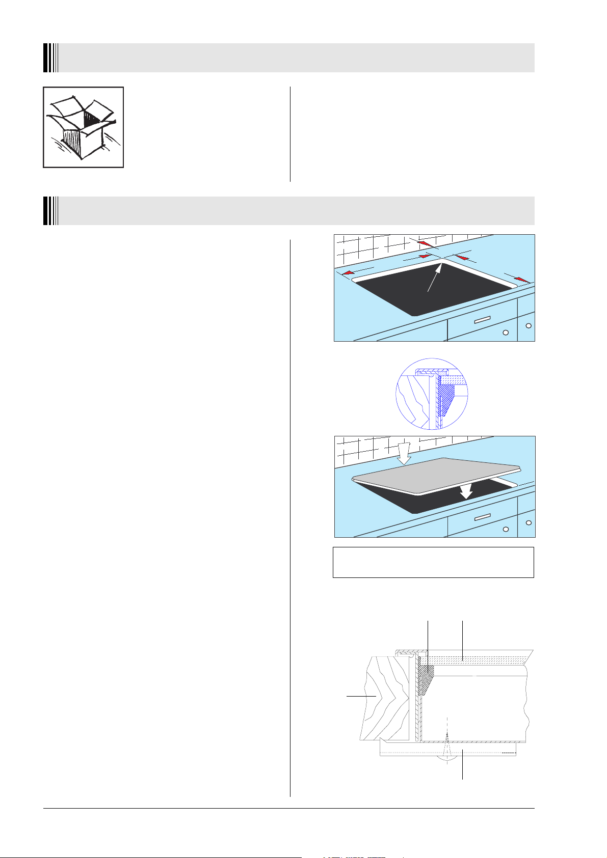
PREPARATION FOR INSTALLATION
Cut out worktop to prescribed measurements or
templates (saw exactly along the scribing).
Check seal for perfect fit and overall cover.
Lower the ceramic hob into place and align correctly.
In terms of fire protection, the appliance conforms
to Type Y (IEC 335-2-6). Only appliances of this type
may be installed on one side of adjacent upright
furniture housings or walls.
55
560 –1
R 5
490 –1
1
2
hob dimensions: 572 x 502 mm
cut out dimensions: 560 x 490 mm
Fastening according to Fig. 1
Fasten bracket against the underside of the worktop.
Using a standard or Phillips screwdriver, tighten the
tension clamps evenly starting at the centre and
moving diagonally, until the built-in rim is tight on the
worktop.
Do not overtighten!
Do not use an electric or pneumatic screw driver
without an adjustable safety clutch! (pos. 1 - 1.1 Nm)
12
fig. 1 sealing ceramic glass
worktable
bracket
Page 5

ELECTRICAL CONNECTION
The electrical connection of the
ceramic hob to the specially provided built-in switch box and to the
built-in range should only be carried
out by a trained technician.
During assembly the switch box and
the stove must be idle.
Connect cable-plug with appropriate receptacle fixed on
range or controlbox.
Furthermore attention should be paid to the assembly
instructions for the built-in switch box or oven with which
the hob is connected!
Protection against accidental contact must be ensured
by assembly.
If the hob is operated from a switch box then it is
necessary to have an intermediate bottom to ensure
protection against accidental contact!
The distance between the underside of the hob and the
furniture beneath must be at least 20 mm.
Arrangements of hob - built - in oven/switch box may be
looked-up in a special table which is an appendix to
these instructions.
Before installation and operation of the appliance the
range of possibilities for combining the hob with the oven/
switch box is to be checked by referring to the appropriate
instructions for installation and operation.
Using other hobs than those of ZANKER-Brand excludes any liability.
If these regulations are not observed all given
approvals of test institutes are void.
Important for the disassembly of the hob
The supply of mains current to the appliance must be cut
off (for example by unscrewing the safety devices).
13
Page 6

BEFORE THE FIRST USE
Clean your ceramic hob thouroughly before its first use.
Ceramic hobs are treated and cleaned the same way as
glass.
When you use the ceramic hob for the first time it can
temporarely emit an odeur caused by the vaporation of
water in the isolation.
DESCRIPTION OF APPLIANCES
ZKM 3013 KB/KW/KN/KS
1. Cooking zone ∅ 180 mm, 1700 W
2. Cooking zone ∅ 145 mm, 1200 W
3. Cooking zone ∅ 180 mm, 1700 W
4. Cooking zone ∅ 145 mm, 1200 W
5. Residual heat indicator
OPERATING INSTRUCTIONS
Cooking zones
The cooking zones are clearly marked on the ceramic
surface. Only the cooking zone which is switched on will
be heated up. The remaining surface will not get hot.
Residual heat indicator
Each cooking zone is related to one indicator. The
warning lamp lights up when the surface of the
corresponding cooking zone reaches a temperature
which could cause burning.
This lamp remains lit after the heated-up area has been
switched off as long as the residual heat of the
corresponding cooking surface can cause burnings.
The light will only extinguish when there is no more
danger (temperature below 50°C).
The remaining heat should be used to get food readycooked or keep food warm.
14
Page 7

COOKING EQUIPMENT
Specially tested cooking and frying pans for ceramic
hobs exist. Pay attention to the declaration of the
manufacturer.
Cooking pans with aluminium or copper bottoms
can cause metallic discolouration that can not
removed anymore. Be especially careful in using
enamel pans. Avoid the heating-up of empty pans
since their base could be damaged in a way which
can cause scratches when removed on the hob's
surface.
The following advice should be considered to
achieve an optimal energy consumption as well as
to avoid that overboiling food can be burnt onto the
cooking zones.
Bottom of pans:
Cooking and frying pans should have a flat and solid
base. A base with rough edges can scratch and leave
abrasion marks on the ceramic surface! Ask for electric
saucepans.
Size of pans:
Pan or pot diameters should correspond to the diameter
of the cooking zone.
The ceramic hob surface is resistant to extreme
temperatures. Neither cold nor heat can harm it. Avoid
to drop anything on the hob. Punctiform impacts, e.g. by
the fall of a salt shaker, can cause fissures and cracks.
If any cracks appear on the hob surface, the hob has
to be switched off immediately. Disconnect the appliance
from the mains and inform the service department.
Lid of pans:
A lid prevents heat to escape, shortens the heating-up
time and reduces the energy consumption.
Note:
Prevent little children from touching the cook top
when in use. Children also can burn themselves by
pulling pans or pots off the hob.
The cooking zones heat up quickly when they are
turned on. Turn them on only when you have placed a
saucepan onto the cooking area.
Be careful by using the hob as a working-table or when
depositing items on the hob's surface. The items you
place on the hob could easily catch fire when turning on
the hob accidentally. Afterwards the hob should be
cleaned thoroughly.
Sugar (solid or liquid) as well as plastic should never
get onto the hot surface of the hob. Also, never use
plastic or aluminium foil dishes. They melt at high
temperatures and can cause fissures and cracks when
the hob cools down. Spills of sugar or melted plastic
material must be removed while the hob is still warm and
before the remains have set.
Scrape off the remains of sugar or plastic with a scra-per.
Protect your hands.
15
Page 8

MAINTENANCE
The maintenance remains the same
for glass and ceramic hobs. Never
use aggressive detergents or scouring powder and sponges with abrasive surfaces.
Cleaning after each use
Slight, not burnt soiling has to be wiped off with a
damp cloth without using detergents. The use of
detergents may lead to discolouring. These heavy stains
can not be wiped off easily by the first attempt and
sometimes not even with a special detergent.
Burnt soiling has to be removed with a scraper.
Afterwards wipe off the ceramic hob with a damp cloth.
Stain removal
Light metallic stains (aluminium remains) can be
removed from the cooled down cooking zone with a
special detergent. Calcareous deposits (caused by
overboiling water) can be removed with vinegar or a
special detergent.
Removal of sugar, sugar-containing food, plastic
objects or kitchen foil
The cooking zone involved must not be turned off! The
remains have to be scraped off the hot cooking zone
immediately with a scraper. The cooking zone can be
switched off after the removal of the soiling. It may be
cleaned with a special detergent after it has cooled down.
The mentioned detergents are available in supermarkets, electrical shops, drug stores, grocery stores
and kitchen studios.
Scrapers are available in craft shops and department
stores as well as in decoration stores.
Do not apply detergents on hot cooking zones. Best
is to the detergent dry on the surface and to wipe it off with
a damp cloth. If there are remains of cleaning agents
wipe them off before you turn on the heat again. Remains
could corrode.
We decline any liability should the appliance be
used improperly and the safety measures not be
observed.
16
Page 9

TECHNICAL DATA
Rating plates:
Hob dimensions : width : 572 mm
depth : 502 mm
height : 43 mm
Cut out dimensions : width : 560 mm
depth : 490 mm
Voltage : 230 V ~ 50 Hz
Total power : 5.8 kW
WHAT TO DO IN CASE OF A DEFECT
Before you call the customer
service make sure that the hob
was operated correctly and the
fuse is not blown out.
Typ 076.0 Ser.Nr.
T.Nr.402689 230V ~ 50 Hz 5.8 kW
Typ 076.0 Ser.Nr.
T.Nr.402690 230V ~ 50 Hz 5.8 kW
Typ 076.0 Ser.Nr.
T.Nr.402691 230V ~ 50 Hz 5.8 kW
Typ 076.0 Ser.Nr.
T.Nr.402692 230V ~ 50 Hz 5.8 kW
ZKM 3013 KB
ZKM 3013 KW
ZKM 3013 KN
ZKM 3013 KS
Prod.Nr. 941 683 648
SWISS MADE
Prod.Nr. 941 683 649
SWISS MADE
Prod.Nr. 941 683 650
SWISS MADE
Prod.Nr. 941 683 651
SWISS MADE
Attention!
If any fissures or cracks appear on
the hob's surface the hob has to be
switched off immediately.
Disconnect the appliance from the mains and inform the
service department.
Repairs on electrical appliances must be undertaken by qualified electricians only. Improper repairs
can cause serious harm and danger for users.
The appliance is only disconnected from the mains
when the fuse is turned off or the mains connection
is interrupted.
Important!
Following details are necessary for the service department:
type ...........................................................................................................................................
model ...........................................................................................................................................
product-no. ...........................................................................................................................................
You will find these details under "Technical data" on the
rating plates.
Technical changes are subject to modification.
17
Page 10

ZKM 3013 KB Prod. no. 941 683 648
ZKM 3013 KW Prod. no. 941 683 649
ZKM 3013 KN Prod. no. 941 683 650
ZKM 3013 KS Prod. no. 941 683 651
ZKH 7012 B/W/S/X
ZKH 7214 B/W/S/X
51
Page 11

01.94 374 1053-01
 Loading...