

Page 1
3017M Chlorine Analyzer
DPD CHLORINE ANALYZER
USER MANUAL
332100_Rev A
Page 2

General Information
The information contained in this manual is subject to change without notice.
Effort has been made to make the information in this manual complete, accurate, and current.
The manufacturer shall not be held responsible for errors or omissions in this manual, or for incidental or consequential
damages in connection with the furnishing, performance, or use of this material.
No part of this document may be reproduced, photocopied, or translated to another language without the prior written
consent of YSI.
Consult YSI.com for the most up-to-date version of this manual.
Warranty
YSI warrants each YSI manufactured product against defects in materials and workmanship under normal use
and service for a period of two years. Equipment installed by YSI is warranted from the installation date; all other
equipment is warrantied from the ship date. If purchaser schedules or delays installation more than 90 days after
delivery, then the warranty period starts on the 91st day from date of shipment. This warranty extends only to the
original purchaser. YSI will, at its option, repair or replace equipment that proves to be defective during the warranty
period, provided the equipment is returned to YSI at the expense of the purchaser.
Consumables, expendables, and parts are warranted for 30 days and are not covered under extended warranties or
service contracts.
YSI warrants for a period of one year from the date of delivery: (i) the software, when installed and used with an YSI
recommended hardware configuration, will perform in substantial conformance with the documentation supplied with
the software; and (ii) the physical media on which the software is furnished will be free from defects in materials and
workmanship under normal use.
This warranty shall not apply to defects originating from, but not limited to, the following:
• Improper maintenance or operation by the purchaser;
• Purchaser-supplied accessories or consumables;
• Modification or misuse by the purchaser;
• Operation outside the product’s environmental and electrical specifications;
• Software, interfacing, parts, or supplies not supplied by YSI;
• Improper or inadequate site preparation;
• Purchaser-induced contamination or leaks.
THE FOREGOING WARRANTY IS IN LIEU OF ALL OTHER WARRANTIES, EXPRESSED OR IMPLIED, INCLUDING
BUT NOT LIMITED TO ANY WARRANTY OF MERCHANTABILITY, FITNESS, OR ADEQUACY FOR ANY PARTICULAR
PURPOSE OR USE. YSI SHALL NOT BE LIABLE FOR ANY SPECIAL, INCIDENTAL, OR CONSEQUENTIAL DAMAGES,
WHETHER IN CONTRACT, TORT, OR OTHERWISE.
Any service requests or questions should be directed to the YSI Customer Support Center at (937) 767-7241.
1
Page 3
Safety Information
Please read this entire manual before unpacking, installing and operating this instrument. Ensure that the protection
provided by the instrument is not impaired. Do not install or use this instrument in any manner other than that specified
in this manual. For operator safety, pay attention to DANGER, WARNING and CAUTION statements throughout the
manual.
Safety Hazard Information
DANGER indicates a potentially or imminently hazardous situation which, if not
avoided, will result in serious injury or death.
WARNING indicates a condition or possible situation that could result in physical
X
injury to the operator.
CAUTION indicates a condition or possible situation that could damage or destroy
the product or the operator’s work.
NOTE: Information that is supplemental to the point in the main text.
Follow warnings and precautions in this manual or on the instrument during operation, service and repair. Failure to
follow these warnings and precautions violates the safety design standards and intended use of the instrument. YSI is
not liable for the operator’s failure to comply with these warnings and precautions.
Precautionary labels
Please read all labels and tags attached to the instrument. Personal injury or damage to the instrument could occur if
not observed.
Electrical equipment marked with this symbol may not be disposed of in the European
public disposal systems after 12 August 2005. In conformity with European local and national
regulations (EU Directive 2002/96/EC), European electrical equipment users must now return
old or end-of-life equipment to the Producer for disposal at no charge to the user.
NOTE: For return for recycling, please contact the equipment producer or supplier for
instructions on how to return end-of-life equipment, producer-supplied electrical accessories,
and all auxiliary items for proper disposal.
2
Page 4

TABLE OF CONTENTS
1. General Product Information..........................................4
1.1 Instrument Description...........................................4
1.2 Instrument Specifications.......................................5
1.3 Method of Analysis..................................................6
1.4 Theory of Operation................................................6
2. Installation...........................................................................7
2.1 Unpack the Analyzer................................................7
2.2 Environmental Considerations..............................7
2.3 Analyzer Mounting..................................................7
2.4 Plumbing Connections.........................................10
2.5 Sample Line...........................................................10
2.6 Sample Inlet Device............................................10
2.7 Optional In-Line Filter.........................................13
2.8 Sample Inlet Devices and Systems......................13
2.9 Electrical Connections........................................13
2.9.1 Power Connections.................................13
2.9.2 Wiring the Analyzer.................................14
2.9.3 RS 485.......................................................15
2.9.4 Analog Output (4-20 mA)......................15
2.9.5 Alarm (Relay) Connections.....................15
2.9.6 AC Connections.......................................16
2.9.7 Reagent Preparation................................16
2.10 Pump Tubes..........................................................17
2.10.1 Sample Pump Tube...............................18
2.10.2 Reagent Pump Tubes............................19
3. Analyzer Startup...............................................................20
3.1 Supply the Sample..............................................20
3.2 Supply Power to the Analyzer............................20
3.3 Language Selection............................................21
3.4 Powerup Mode....................................................21
4. Analyzer Operation..........................................................22
4.1 User Interface.......................................................22
4.2 Display...................................................................23
4.3 Touchpad..............................................................23
4.4 Firmware Structure & Operation.......................23
4.5 Unlocking/Locking the Analyzer.......................32
4.6 Method Settings..................................................33
4.7 Setting the 4-20mA Output...............................33
4.8 Setting the Alarm/Timed Event Relays.............33
4.8.1 Setting Alarm Relays with Keypad........33
4.8.2 Setting Alarm Relays w/ MODBUS........34
THIS IS AN INTERACTIVE
ADOBETM PDF DOCUMENT
4.9 Calibration............................................................34
4.9.1 Calibration with Known Standard.........34
4.9.2 Calibration by Comparison....................35
5. Default Configuration & Method Settings..................36
5.1 Method Settings..................................................36
5.1.1 Times.........................................................36
5.1.2 Pumps........................................................37
5.1.3 LEDs..........................................................37
5.2 Setup.....................................................................37
5.2.1 Communications......................................37
5.2.2 4-20 mA Setup.........................................38
5.3 Status......................................................................38
5.4 Linearization.........................................................38
5.5 Maintenance.........................................................38
6. Maintenance......................................................................39
6.1 Regularly Scheduled Maintenance...................39
6.1.1 Reagent Replacement.............................39
6.1.2 Pump & Reagent Tube Replacement....39
6.1.3 Flowcell Cleaning....................................41
6.2 Unscheduled Maintenance................................41
6.2.1 Fuse Replacement...................................41
6.2.2 Linearization.............................................42
6.2.3 Field Linearization Procedure................42
7. Troubleshooting...............................................................45
7.1 Troubleshooting Guide......................................45
7.2 Using Manual Controls & STATUS Screen.......46
7.3 UsingTier 3 Selections & STATUS Screen........47
7.3.1 Main STATUS Screen...............................48
7.3.2 Liquid Level Sensor & Error Levels.......49
7.3.3 Firmware & PCA Revision Levels...........51
8. Parts & Accessories...........................................................52
9. Declaration of Conformity..............................................59
10. Appendix A: MODBUS Manual...................................60
3
Page 5

1. General Product Information
1.1 Instrument Description
DANGER Chemical or biological hazards: If this instrument is used to monitor a treatment process
and/or chemical feed system for which there are regulatory limits and monitoring requirements
related to public health, public safety, food or beverage manufacture or processing, it is the
responsibility of the user of this instrument to know and abide by any applicable regulation and to
have sufficient and appropriate mechanism in place for compliance with applicable regulations in
the event of malfunction of the instrument.
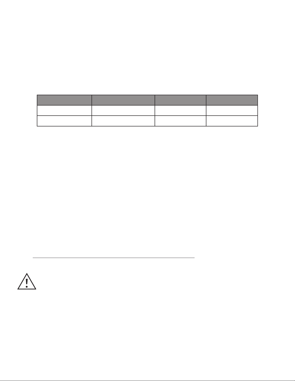
The 3017M Chlorine Analyzer is a microprocessor-controlled process analyzer. It is designed to continuously monitor
an aqueous sample for chlorine content. Either free or total chlorine, in the range of 0 – 5 mg/L can be monitored.
Indicator and buffer solutions are used for the determination of chlorine content. Specific buffer solutions are used for
free or total chlorine.
WARNING Fire hazard: This analyzer is intended to be used for aqueous samples only.
The 3017M Chlorine Analyzer enclosure is rated for IP 66 per IEC 529. The enclosure is dust tight and drip
resistant and is designed for outdoor use. However, a three-sided covering that prevents direct exposure to
sunlight, dripping water, rain, sleet, or snow should be used.
The 3017M Chlorine Analyzer is an on-line photometric analyzer that uses N,N-diethyl-p-phenylene diamine (DPD)
indicator and a buffer to determine chlorine content. The system has two peristaltic pumps that deliver sample and
reagents to the flowcell. The sample pump continually delivers sample to the flowcell. The reagent pump is activated at
a predetermined time to deliver buffer and DPD reagent to the sample stream.
The flowcell consists of a sample inlet, reagent inlets, a static mixer and sample drain. Either a green, blue, or red LED
can be selected to provide the appropriate wavelength of light. Light is transmitted through fiber optic cables through
the flowcell and back to a dual-channel detector. One channel is used for the analysis of the colored complex while the
other channel is used as a reference to monitor the LED source, and thereby, maintain stability
of the system.
The reagents are dispensed from two replaceable bottles. One bottle has a buffer to control the pH; the second bottle
has the DPD reagent that produces a magenta color when chlorine is present in the sample. The degree of color
change is proportional to the amount of chlorine in the sample water. Chlorine concentration is displayed on the front
panel by three-digit LCD readout in mg/L chlorine.
The system accepts commands and sends data over RS-485 using Modbus RTU/ASCII protocols, or through the
touchpad, if the instrument is not operated under Modbus control. A 4-20 mA output is available for connection to
an external datalogger, Programmable Logic Controller (PLC) or Distributive Control System (DCS). Concentration
minimum and maximum values in mg/L chlorine are set by the operator at the analyzer touchpad.
Programmable alarm circuits provide relay closures, both normally open and normally closed, for two selectable
chlorine level set points. Set points can be programmed by the operator anywhere in the overall range. System
warning and system alarm features provide automatic, self-testing diagnostics that detect a number of possible
malfunctions, and provide alarm relay closures indicating a need for operator intervention.
Indicator and buffer reagent containers (500-mL each) are placed in the instrument enclosure. Reagents are
replenished once a month when operating in the 0 – 5 mg/L chlorine range. A clear front cover allows for viewing of
reagent bottles, and other critical components without the need for opening the analyzer enclosure.
4
General Product Information
Page 6

1.2 Instrument Specifications
Performance
Measurement Method N, N-Diethyl-p-phenylenediamine (DPD)
Measurement Range 0-5 mg/L free or total chlorine, reagent dependent
Measurement Interval Programmable; 2.5 to 60 minutes
Accuracy ±0.03 mg/L or ±5%, whichever is greater
Limit of Detection 0.03 mg/L
Calibration Factory calibrated, 1-point if required
Resolution 0.01 mg/L
General
Display 2.8 x 6 cm backlit LCD
Enclosure IP66 (with door latched)
Instrument Dimensions 17.6 x 14.7 x 7.9 inches (44.6 x 37.3 x 18.8 cm)
Mounting 4 mounting struts bolted to back of unit
Instrument Shipping Weight <18 lbs ; 8 kg
Warranty 2 year warranty
Regulatory Compliance US EPA regulations 40 CFR 141.74 and 40 CFR 136.3; Standard method
4500-CL-G; US EPA method 334.0; ISO method 7393-2
Certification CE, cETLus
Language English, French, German, Italian, Spanish
Sample Requirements
Sample Flow Rate to Sample Inlet Device 50 to 1,000 mL/min when using Sample Inlet Device
Inlet pressure 1 to 20 psig with Sample Inlet Device
Sample Temperature Range 41 to 113 °F (5 to 45 °C)
R R
Reagent Sets 330006 - Reagent set for measuring total chlorine
330007 - Reagent set for measuring free chlorine
Reagent Consumption ~30 days per bottle at a 2.5 minute measurement interval
Reagent Storage Life (before hydration) Buffer and indicator: 5 years
DPD powder: 1 year
Reagent Storage Life (after hydration) ~30-40 days
Power & Communication
Power 115-230 VAC , 50-60 Hz, 70VA
Relays Two relays rated at 6A, 30VDC
Analog Output One 4-20 mA configurable output
Digital Output RS-485 Modbus RTU
Optical
Light Source Class 1 LED; wavelength centered at 525 nm
Light Path Length >1 cm
Environmental
Storage Temperature Range 41 to 158 °F (5 to 70 °C)
Operating Temperature Range 41 to 131 °F (5 to 55 °C)
Relative Humidity 90% at 40°C non-condensing
General Product Information
5
Page 7

1.3 Method of Analysis
Free available chlorine (hypochlorous acid and hypochlorite ions) oxidizes the DPD indicator reagent at a pH between
6.3 and 6.6 to form a magenta-colored compound (Würster dye). The intensity of the resulting color is proportional to
the concentration of chlorine in the sample. A buffer solution specifically for free chlorine maintains the proper pH.
Total available chlorine (free chlorine and combined chloramines) is determined by adding potassium iodide to the
reaction. Chloramines in the sample oxidize iodide to iodine, which, along with any free available chlorine, oxidizes
DPD indicator to form the magenta color at a pH of 6.5 – 8.5. A different buffer solution containing potassium iodide
maintains the reaction pH. After the chemical reaction is complete, the optical absorbance at the selected wavelength
is compared to the absorbance measured through the flowcell before the reagents are added. Chlorine concentration
is calculated from the difference in absorbance.
1.4 Theory of Operation
The sample continuously flows through the flowcell. Prior to the addition of reagents, the blank absorbance is
measured. Measurement of the sample blank allows for compensation for any turbidity or natural color in the sample
and provides an automatic zero reference point. Reagents are added after the measurement of the blank sample and
develop the magenta color if chlorine is present in the sample. Absorbance is measured and compared to the blank
reference value.
Peristaltic pumps control the flow of sample and reagents. The sample flows continuously and the reagent pump
delivers a metered amount of buffer and indicator in a 2.5-minute cycle. The cycle operates as follows:
1. The sample is continuously flowing through the flowcell.
2. At a preset time, the absorbance of the blank sample is measured.
3. After the blank absorbance is measured, the indicator and buffer reagents are injected into the flowing stream
of sample.
4. The sample and reagents are allowed to thoroughly mix for the full development of the magenta color. The
measurement of the treated sample is taken to determine the chlorine content.
5. The sample pump increases the flow rate to thoroughly evacuate the flow cell in preparation for the start of the
next cycle.
6
General Product Information
Page 8

2. Installation
DANGER Electrocution and fire hazard. Only qualified personnel should conduct the tasks
described in this section of manual.
WARNING Electrocution hazard. Install a 10A circuit breaker for main power. Identify the circuit
breaker with a label, as a local disconnect for this equipment.
2.1 Unpack the analyzer
Remove the analyzer from the box and inspect it for damage. Verify that all of the parts are contained in the shipment.
If any items are missing or damaged, contact Technical Support, or the local representative.
2.2 Environmental Considerations
The analyzer enclosure is designed for indoor or outdoor installation with an ambient temperature range of 5 – 55 °C
(18 – 131 °F). The enclosure environmental rating is IP 66 with the door closed and latched. For outdoor installation, the
analyzer should be covered by a three-sided cover to protect it from direct sunlight, dripping water, rain, sleet or snow.
2.3 Analyzer Mounting
The enclosure is designed for wall mounting. Refer to Figures 2.1, 2.2, 2.3 and 2.4 for critical dimensions and other
installation information.
The 3017M has four mounting tabs that must be installed on the enclosure refer to Figure 2.2. These mounting tabs
can be found in a package of mounting hardware that is included with the enclosure. Connect the mounting tabs
to the enclosure using the four (4) #10-32 x 3/8-inch Phillips Drive flat head machine screws found in the mounting
hardware kit.
Use ¼-inch screws, or bolts, depending on mounting location/surface. The analyzer should be mounted at a height
at which it can be safely operated. Mount the analyzer as close as practical to the sampling point to ensure complete
purging of the sample line during each cycle. Leave adequate clearance at the sides and bottom of the analyzer
enclosure for wiring and plumbing connections.
The most common installation approach is the use of Unistrut® frame. Unistrut frame with ¼-inch spring nuts would be
used for mounting the 3017M. The mounting tabs on the 3017M are designed for ¼-inch bolts.
NOTE: The sample pump in the analyzer pulls sample into the flowcell. The maximum distance between the analyzer
and the sample point should not exceed 3.28 ft (1 m).
Installation
7
Page 9
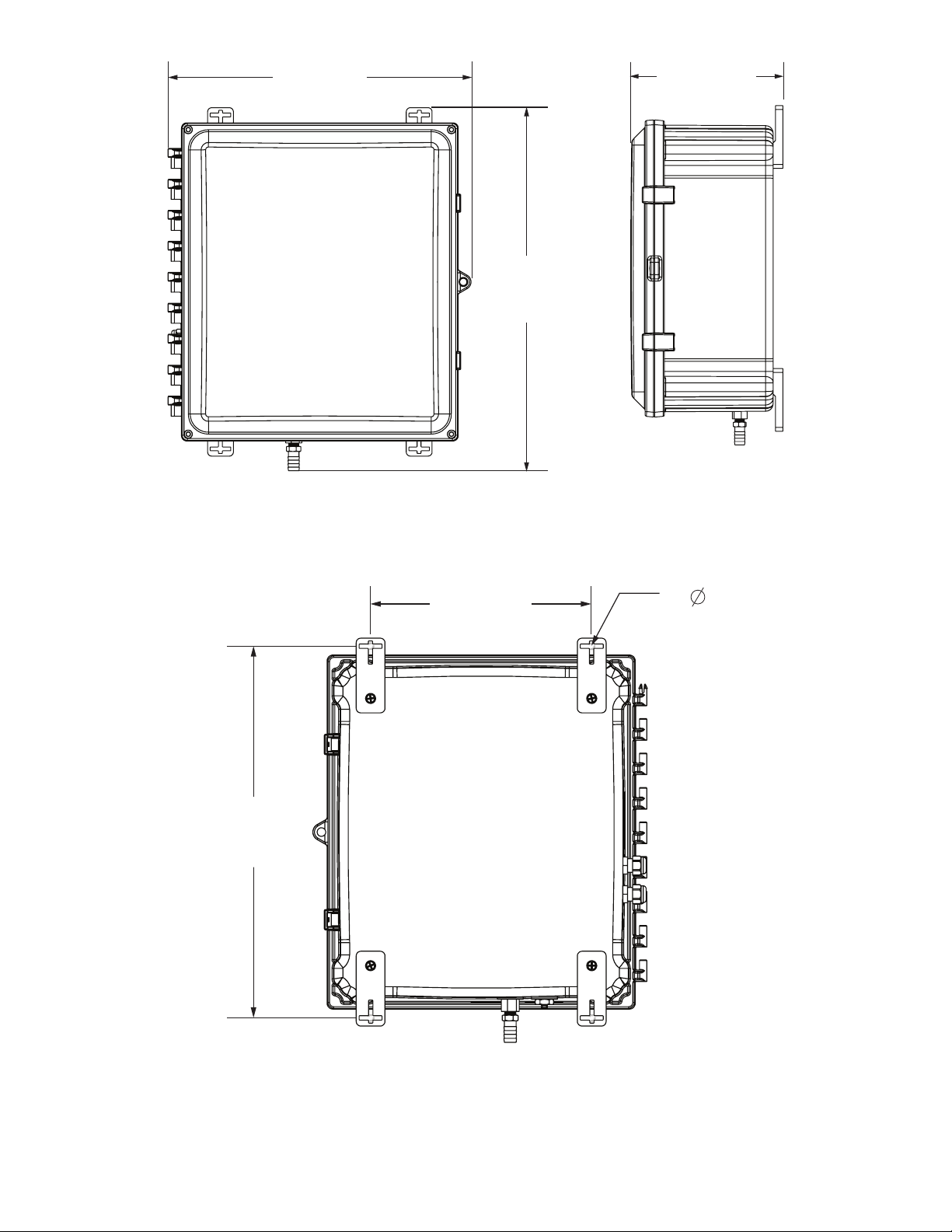
14.674”
(37.27 cm)
7.891”
(20.04 cm)
17.582”
(44.66 cm)
Figure 2.1 3017M overall dimensions
16.172”
(41.08 cm)
9.625”
(24.45 cm)
4X .250” MOUNTING HOLE
(.635 cm)
Figure 2.2 3017M mounting dimensions showing the mounting tabs connected to the enclosure
8
Installation
Page 10
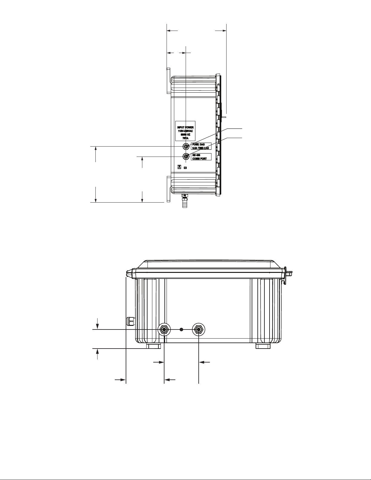
7.361”
(18.70 cm)
2.393”
(6.08 cm)
POWER CONNECTIONS
RELAY/ALARM & NETWORK
CONNECTIONS
7.000”
(17.78 cm)
1.736”
(44.08 cm)
5.745”
(14.59 cm)
Figure 2.3 3017M electrical connections
Installation
2.988”
(75.88 cm)
3.475”
(88.26 cm)
Figure 2.4 3017M plumbing connections
9
Page 11

2.4 Plumbing Connections
NOTE: The waste line contains analysis waste, which include both sample and chemical reagents. The chemicals used
for the analysis are of very low concentrations. Adhere to local codes for the proper disposal of this waste.
Sample inlet and waste connections are made on the bottom of the analyzer. The sample inlet is a quick connect fitting
for a 1/8-inch (3.175-mm) OD tubing. The waste line is a barb fitting for ½-inch (12.7-mm) ID flexible tubing. See Figure
2.4. Connect the 1/8-inch (3.175 mm) OD Teflon® by pushing it into the fitting. A stop will be felt when the tubing is
properly seated in the fitting. Connect the waste line by pushing, and gently twisting, the tubing over the barb on the
fitting. Ensure that the tubing completely covers the barb.
NOTE: No pressure, positive or negative, should be applied to the waste line. Never plug the waste line.
CAUTION Fire hazard. This analyzer is intended for water samples only.
2.5 Sample Line
The selection of a representative sample is important for optimal performance of the analyzer and analytical results.
The sample must be representative of the condition of the entire process. Erratic reading will be realized if the sample
is drawn from a location that is too close to the point of chemical injection, if mixing is incomplete, or if the chemical
reaction is incomplete.
Install sample line taps into the side or center of larger process pipes to minimize the chance of ingestion of sediment
or air bubbles. A tap projecting into the center of a pipe is an ideal configuration. Opaque tubing is recommended if
the tubing is exposed to sunlight in order to prevent algae growth.
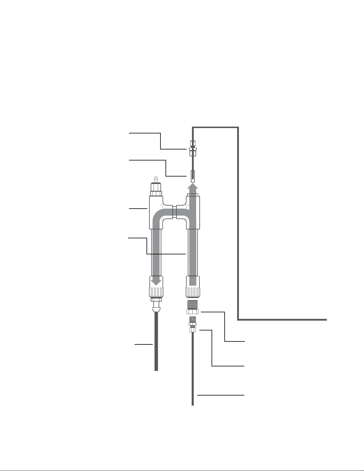
2.6 Sample Inlet Device
The Sample Inlet Device, part number 327114, is shown in Figure 2.5. It is a simple, easy-to-use device that serves as
the interface between the sample tap and the 3017M. It consists of inlet and outlet ports, a 60-micron filter for filtration
of fine particles, if necessary, and a 20-psig pressure relief valve. The Sample Inlet Device is rated for line pressure in
the range of 1 – 20 psig (0.069 to 1.38 bar). It may be necessary to install an in-line pressure regulator, or shut-off valve
upstream of the Sample Inlet Device.
These instructions cover the plumbing connections for the Sample Inlet Device, part number 327114. See Figure 2.5.
Other sampling schemes can be used with the 3017M. The critical point is that the sample inlet line from the 3017M is
always immersed in sample that is representative of the process that is being monitored.
The instrument is designed to require very little head pressure to operate. If the Sample Inlet Device is being used the
pressure range is 1 psi (0.069 bar) to 20 psi (1.38 bar). The maximum allowable fluid temperature is 50°C (122°F).
Opaque tubing is recommended if the tubing is exposed to sunlight in order to prevent algae growth. Note that the
sample inlet and outlet connectors are compatible with ¼-inch (6.35-mm) O.D. flexible tubing. The outlet port of the
Sample Inlet Device has a pressure relief valve that will open if the sample pressure through the device exceeds 20-psi
(1.38 bar).
The 1/8-inch (3.175-mm) sample inlet line from the analyzer to the Sample Inlet Device will be connected to sample
inlet side of the Sample Inlet Device through a bored-through, Swagelok® fitting with a Teflon® ferrule.
10
Installation
Page 12
The analyzer has a separate drain for the flow from the sample and reagent pumps onboard the analyzer. The drain
tubing is ½-inch (12.7-mm) flexible tubing.
NOTE: The analyzer drain must be open to the atmosphere. No pressure, positive or negative, must be applied to the
drain tube.
NOTE: The waste from the drain connection of the instrument contains reagents diluted with large quantities of water.
Route the drain line from the analyzer to the appropriate point in accordance with local codes or regulations.
The ideal location for the Sample Inlet Device is below the 3017M and as close as practical to the 1/8-inch (3.175 mm)
quick connect fitting at the bottom of the analyzer. The installation location of the Sample Inlet Device should not
exceed 3.28 ft. (1 m) from the analyzer. See Figure 2.6.
1/4” NPT to 1/8” TUBE
BRASS FITTING
POLY FILTER 60U
SAMPLE INLET
DEVICE ASSEMBLY
INSERT POLY FILTER ON END
OF 1/8” TUBE TO MIDDLE OF
CLEAR INLET TUBE
1/2” ID URETHANE
TUBING TO DRAIN
1/8” X 1X16” ID
TEFLON TUBING
1/2” TO 1/4” PVC
REDUCING BUSHING
1/4” TO 1/4” TUBE
BRASS FITTING
Installation
1/4” POLY TUBING FROM
FLOW PRESSURE REGULATED
SAMPLE STREAM TAP
Figure 2.5 Sample Inlet Device (part #327114)
11
Page 13
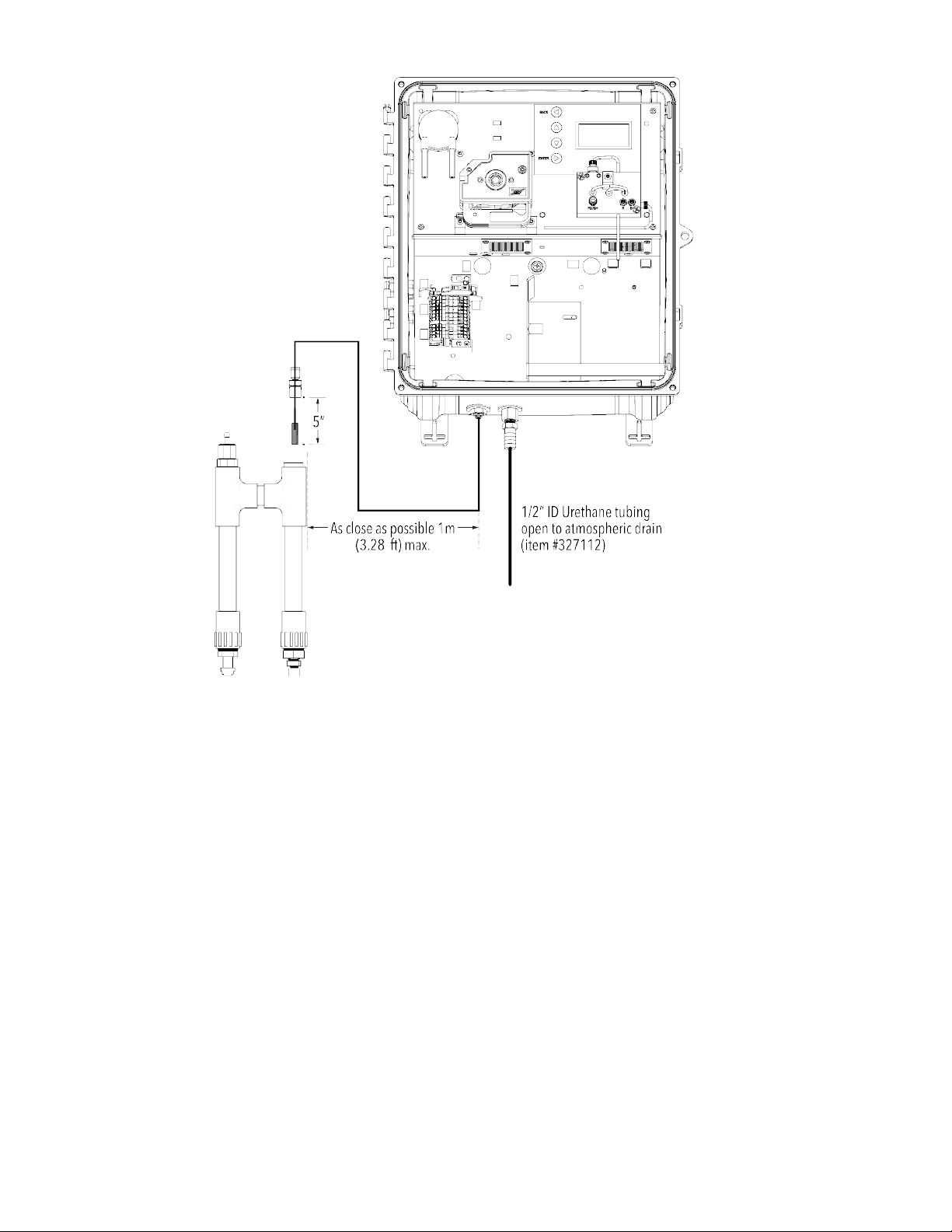
Figure 2.6 Recommended position of the Sample Inlet Device with 3017M
The Sample Inlet Device is supplied with quick connect fittings for ¼-inch (6.35-mm) OD tubing. Other fittings may be
substituted depending on the application, but these are not supplied with the device.
Secure the Sample Inlet Device to the wall, panel, or other structure. Push the ¼-inch OD tubing into the inlet fitting.
A stop will be felt when the tubing is properly seated in the fitting. Repeat this process for the outlet fitting. Route the
outlet tubing to an atmospheric drain, or sump.
Remove the 1/8-inch NPT to 1/8-inch Tube fitting at the top of the Sample Inlet Device. This fitting has Teflon® twopiece ferrule. Take care not to lose it, or over-tighten. It can be reused numerous times if not over-tightened.
Insert the sample pick-up line into the fitting and attach the 60 micron filter to the end of the sample line. Secure the
fitting to the Sample Inlet Device. Position the sample pick-up line/filter at approximately mid-way in the Sample Inlet
Device. Gently tighten (do not overtighten) the 1/8-inch nut on the fitting.
Apply sample to the system and check for leaks. Ensure that the sample from the outlet of the Sample Inlet Device is
flowing freely to the drain.
12
Installation
Page 14

2.7 Optional In-Line Filter
In some applications, the addition of first-stage filtration may be necessary before the Sample Inlet Device. A 40-mesh
strainer is available, but not included with the analyzer.
The 40-mesh strainer may be installed at any point in the sample line prior to the inlet of the Sample Inlet Device.
However, a position in close proximity to the inlet of the Sample Inlet Device is recommended to prevent the build-up
of contamination in the sample line after the strainer.
2.8 Optional Sample Inlet Devices
and Systems
The 3017M Chlorine Analyzer is not absolutely dependent upon a pressurized stream of water. For instance, a sample
may be placed in a container and the sample inlet tube submerged in it. As long as the sample inlet tube shown in
Figure 2.6 is submersed in a representative sample, the Sample Pump on the instrument will draw the sample into the
instrument. Therefore, any number of different sample devices can be used on the 3017M.
The sample inlet tube may be inserted into a flowing stream of water. As long as the recommended distances from
the instrument to the sample point are followed and the sample tube is always fully submersed in water, and steps are
taken to prevent clogging, the Sample Pump should draw water into the analyzer.
2.9 Electrical Connections
The cable glands on the left-hand-side of the analyzer will accept cable diameters from 0.23 in (5.8 mm) to 0.53 in
(13.5 mm). All terminals are designed to accept wires in the range of 14-28 AWG. All wires should be stripped to a
length of 1/4- inch (6.35 mm). Wire ferrules have been found to be particularly useful with the terminal block in the
analyzer.
The power and RS 485/4-20 mA connections are made through the cable glands that are supplied with the analyzer.
The power and RS 48/4-20 mA cable glands can be found on the left-hand-side of the analyzer. See Figure 2.3.
If alternate cable glands are desired, use sealing-type conduit fittings to maintain IEC 529 IP 66 rating. Alternatively,
hard conduit and conduit seals may be used for power and RS 485/4-20 mA connections.
2.9.1 Power Connections
DANGER Electrocution hazard. Only qualified personnel should conduct the tasks described in this
section of the manual. Connect equipment in accordance with national, state and local electrical
codes. When working inside of the enclosure power should be disconnected prior
to entry.
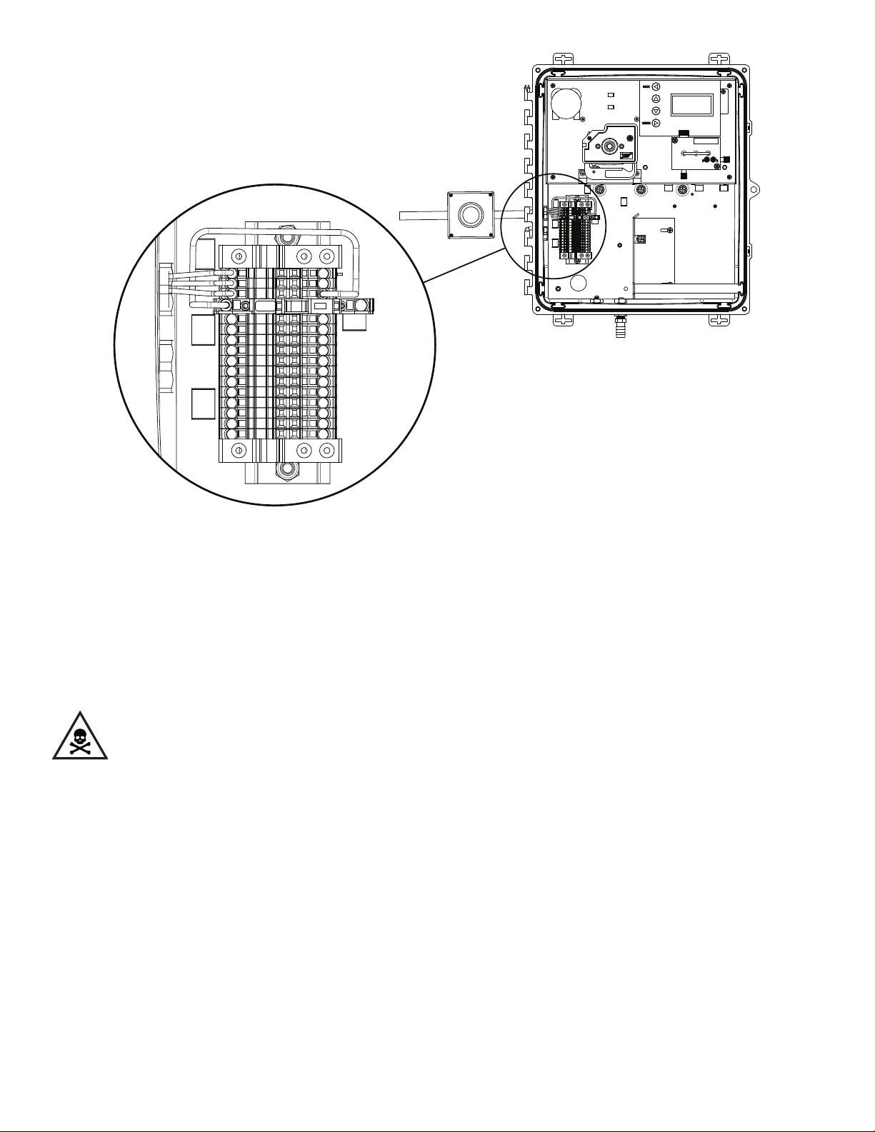
Power, signal, relay and alarm connections are made at the terminal block inside the enclosure on the left-hand-side
of the analyzer. For industrial applications, the national electrical codes of most countries may require that AC service
be hard-wired and contained in rigid conduit systems. The 3017M has been designed to conform to that requirement.
Refer to Figure 2.3.
Additionally, electrical and instrumentation standards require a local means of removing power from a device. The
3017M does not have a power on/off switch. However, a fusible link on the terminal block can be used to
remove power from the analyzer. An external means of removing power from the analyzer may be necessary.
Installation
13
Page 15
External
Power Switch
(optional)
1
2
3
4
5
6
7
8
9
10
11
12
13
14
15
16
Figure 2.7 3017M showing terminal block and external power switch
In applications where power cords are allowed by local electrical code and power surges and transients are not a
concern, a power cord with three 18 gauge wires can be used. The cable gland on the left-hand-side of the analyzer is
compatible with most, standard power AC power cords.
2.9.2 Wiring the Analyzer
DANGER Electrocution hazard. Ensure that the power cord is not connected to outlet, or other
power source.
NOTE: The 3017M can accept either 115 VAC or 230 VAC. There is no voltage selector switch.
The 3017M uses WAGO® connectors for power, signal, and alarm connections. See Figure 2.8 and Tables 1 and 2. The
individual connector blades are opened by inserting the tip of a narrow, flat-blade screwdriver into the square opening
of the connector. Insert the screwdriver tip until it bottoms-out in the connector. Insert the stripped wire and remove
the screwdriver. Gently pull on the wire to ensure that the blades of the connector have secured
the wire.
14
Installation
Page 16
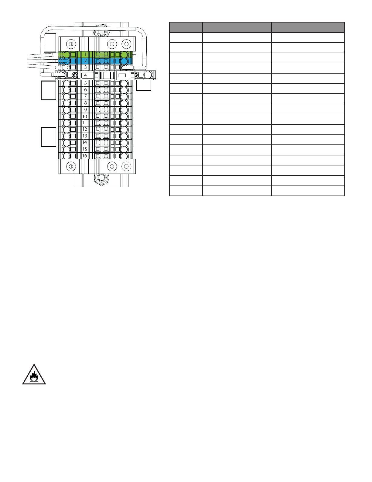
Position Connection/Purpose Wire Color
1 AC Earth Green/Green Yellow
2 AC Neutral (Line 2) White/Blue
3 AC Line (Line 1) Black/Brown
4 Fusible Link (0.5A) Brown
5 RS 485-A White
6 RS 485-B Grey
7 RS 485 RTN Purple
8 4-20 mA (+) Blue
9 4-20 mA (-) Green
10 ALARM 1 (NC) Yellow
11 ALARM 1 (COM) Orange
12 ALARM 1 (NO) Red
13 ALARM 2 (NC) Brown
14 ALARM 2 (COM) Black
15 ALARM 2 (NO) Pink
16 SPARE
Figure 2.8 3017M terminal block
Table 1 Position and purpose for each
wire on the 3017M terminal block
2.9.3 RS 485
The RS-485 full-duplex (3-wire) digital interface operates with differential levels that are not susceptible to electrical
interferences. This is why cable lengths up to 3,000 ft. can be implemented. The last device on each bus may require
terminating with a 120 ohm resistor to eliminate signal reflection on the line. Do not run RS-485 cables in the same
conduit as mains power. Reference Appendix A: MODBUS Manual.
2.9.4 Analog Output (4-20 mA)
The 4-20 mA output is driven by a 12 VDC power source or may be driven by an external power source by changing
the jumper position on the Main Control PCA. The 4-20 mA output will drive loads from 0 to 600 Ohms. Transformer
isolation is provided on the analyzer. Do not run 4-20 mA cables in the same conduit as mains power.
2.9.5 Alarm (Relay) Connections
CAUTION Fire hazard. Current to the relay contacts must be limited to 6A resistive. A method to
remove power from the relays locally must be available in case of an emergency or for servicing
the analyzer.
The analyzer has two potential-free, single pole-double throw Alarm Relays. The relays are rated at 30 V, 6A. The Alarm
connections are labeled Normally Open (NO), Normally Closed (NC) and Common (C). The alarm is configured failsafe; the normal condition is with power applied to the analyzer and in a non-alarm condition.
Installation
15
Page 17
2.9.6 AC Connections (if applicable)
Connect the unpowered, AC power wires to the terminal block as follows:
1. If using a power cord, strip the outer sheath back 4 inches. Strip each individual wire back 1/4 inch (6.35 mm).
If using individual wires, strip each wire back 1/4 inch.
2. Remove the nut from the cable gland and route the power cord through the nut and cable gland into the
enclosure.
3. Pull the power cord back so that the end of the sheath aligns with the inside edge of the cable gland in the
enclosure. This ensures that the nut will tighten on the sheath and seal the connection.
4. Connect the three wires to the proper connector using the information in Table 1, Table 2 and Figure 2.8.
Regional Wire Color Earth Ground Line 1 (Hot) Line 2 (Neutral)
North America Green Black White
IEC Green with yellow tracer Brown Blue
Table 2 Main Power Terminal Wiring
2.9.7 Reagent Preparation
The 3017M requires two reagents; a buffer solution and an indicator solution that contains the DPD powder. These
reagents must be mixed and installed in the analyzer enclosure. The buffer and indicator solutions are mixed in 500-mL
bottles that can be found in either: KIT-FREE CHLORINE, part number 330007, or KIT-TOTAL CHLORINE, part number
330006. Each kit will contain the items below. The containers in the respective kits are clearly marked. The buffer and
indicator bottles are installed on the right-hand side of the analyzer enclosure with the BUFFER in the farthest, righthand position closes to the right side of the enclosure.
1. Diphenylenediamine (DPD) reagent in a small amber glass bottle
2. The 500 mL buffer reagent pre-charged with dry powder and a fill line
3. The 500 mL indicator reagent pre-charged with dry powder and a fill line
4. Instructions for use
NOTE: 1 liter of deionized water (not included) is needed to prepare the reagents. If deionized water is not available,
then use water that is known to be chlorine free. If necessary, test this water with a handheld meter, or other laboratory
test to verify that the water is free of chlorine.
CAUTION The DPD powder must be mixed in the indicator container.
16
Installation
Page 18

Preparing the reagents
1. First prepare the buffer by adding approximately half of the required DI water to the buffer bottle, capping the
bottle, and shaking vigorously until the dry powder inside has completely dissolved.
2. Once solids are no longer visible, carefully fill the bottle to the fill line, recap it, and mix it again by shaking
vigorously for approximately 1 minute. Then let stand until the bubbles clear. The buffer is ready for use.
WARNING Indicator reagent is corrosive. handle with care.
3. Carefully add approximately 1/3 of the required water to the indicator reagent bottle, cap the bottle securely,
and mix it by shaking for approximately 1 to 2 minutes. It is likely there will still be solid material in the bottle.
Add a second one-third of the required water and mix again for 1 to 2 minutes. There should be little-to-no
solid material left in the bottle. If necessary, mix for an additional 1 to 2 minutes, or until all solid material is
in the solution.
4. Transfer the contents of the DPD (brown glass) bottle into the indicator reagent bottle, minimizing the amount
of material left in the brown bottle. Cap securely and shake the indicator bottle, at which time the color should
begin to darken slightly.
5. Carefully add the final amount of water to reach the fill line of the indicator reagent bottle, cap securely and
mix again, then let stand until bubbles clear. The indicator reagent is ready for use.
6. After mixing, the reagents have a shelf life of 30 days at room temperature and 90 days refrigerated at 77° F
(25° C).
Installing the reagents
1. Replace the plain bottle cap with the buffer reagent bottle cap (with siphon tube and barbed fitting) and
place the prepared, colorless buffer in the right bottle bay of the 3017M.
2. Replace the plain bottle cap with the indicator reagent bottle cap (with siphon tube and barbed fitting) and
place the prepared, slightly-colored indicator in the left bottle bay of the 3017M.
3. Carefully connect the pump tubing from the rear reagent pump cassette to the barb on the indicator reagent
bottle and do the same for the front cassette tube with the buffer bottle.
4. Replace the bottle retaining plate to secure the bottles.
2.10 Pump Tubes
WARNING Pinch Point Hazard – While pumps are running it may be possible to become entangled
in them while they rotate. Operators should not attempt to replace tubing while the pumps are in
operation.
WARNING Leak Hazard – A leak detector is advised to be installed into the analyzer to ensure any
leaks will be noticed before causing damage to the analyzer. All barbed connections should utilize
cable ties in order to protect from disconnection.
Installation
17
Page 19
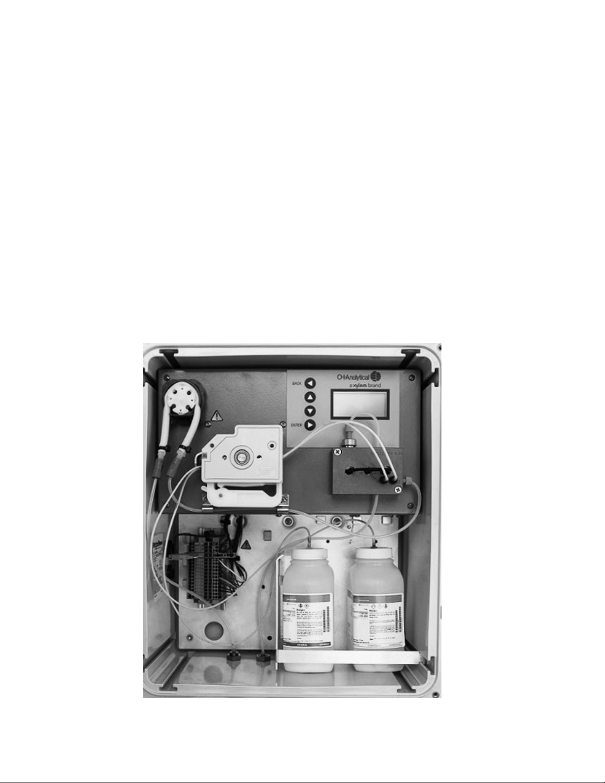
2.10.1 Sample Pump Tube
The analyzer is shipped with the sample pump tube and the reagent pump tubes in place. However, the sample pump
tube must be installed on the sample pump rollers.
1. Refer to Figure 2.9.
2. Remove the cover from the sample pump by placing your finger under the bottom of the cover and gently
pulling outward. Take care to not allow the pump roller to fall out of the assembly.
3. A small package of silicone lubricant, part #331121, will be located on top of the rollers. This will be used to
lubricate the sample pump tube before assembly.
4. Locate the package of silicone lubricant and cut a small opening across one corner of the package.
5. Apply a thin layer of the silicone lubricant to the section of the tube that will mount on the roller in the pump.
A small bead of approximately 3-mm in diameter should be sufficient. Spread the lubricant along the section
of the tube that will contact the pump tube rollers. Do not apply the lubricant in excess. There is sufficient
lubricant in the startup kit for multiple pump tube installations. Remove any excess.
6. Hold the pump tube over the roller, and gently push the roller onto the drive shaft of the pump motor. Your
fingers should be all that is necessary to insert the sample pump tube onto the rollers of the pump. Do not use
any type of sharp tool to position the tube. Damage may result.
7. Position the tube so that it connects so that the barb fitting connections on each end are as even as possible.
Adjust the tube by gently moving back and forth on the rollers.
8. Install the cover.
18
Figure 2.9 Installation of the sample pump tube
Installation
Page 20
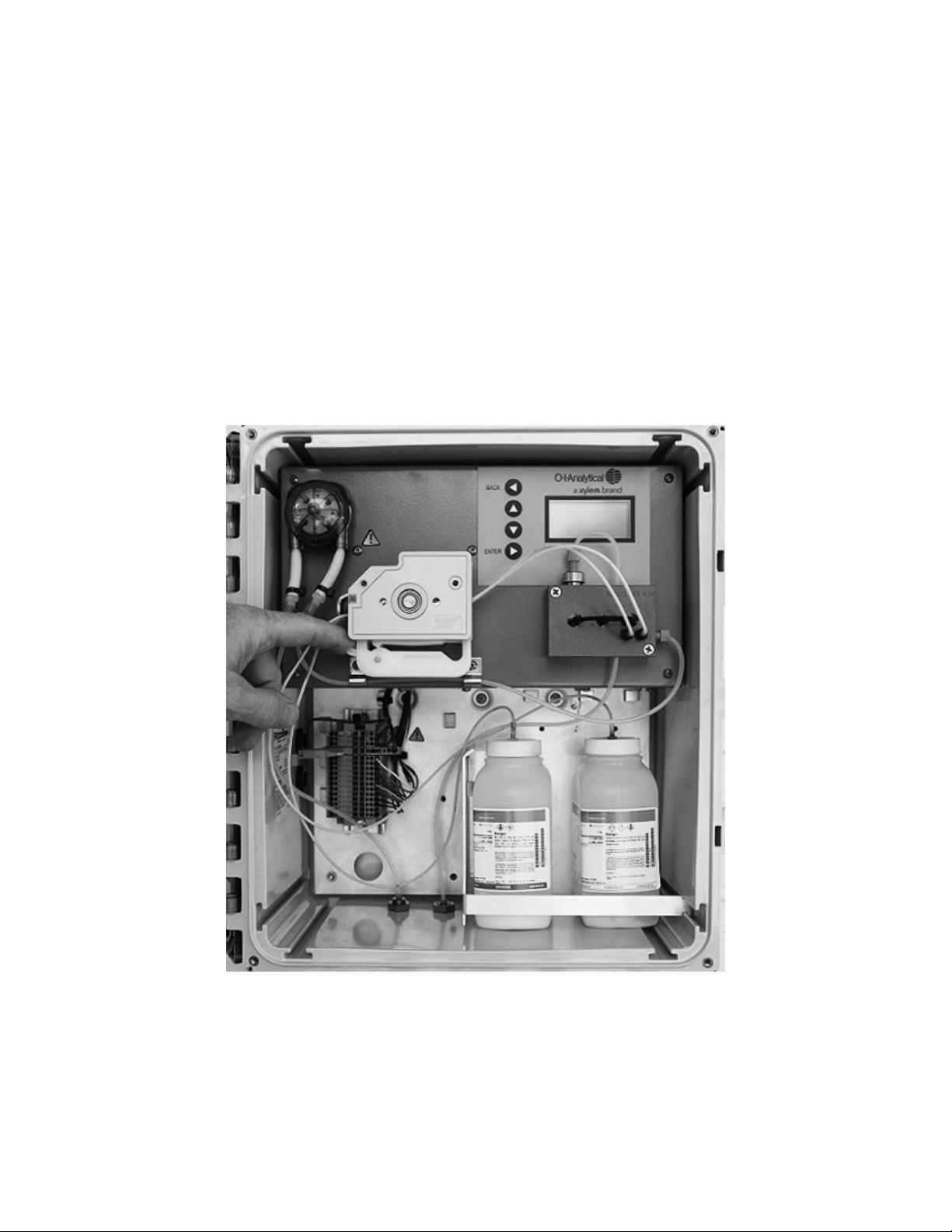
2.10.2 Reagent Pump Tubes
1. The reagent pump tubes are installed in the proper position in the reagent pump. They were connected to
the flowcell at the factory. During the preparation of the reagents, the other ends of the pump tubes were
connected to their respective reagents..
2. Tension the platens by pushing down on the tensioners. The tensioners will make an audible “click”. Typically,
three “clicks” is sufficient tension on the pump tube. Do not overtighten as this may result in premature failure
of the tubes.
3. See Figure 2.10.
4. Installation complete.
Installation
Figure 2.10 Complete reagent tube installation and platen tube tensioning
19
Page 21

3. Analyzer Startup
3.1 Supply the Sample
NOTE: Double-check all fittings to ensure security before applying pressure to the Sample Inlet Device (if used).
Start the sample flowing through the device to which the sample line from the analyzer is attached, or inserted. If this is
the Sample Inlet Device, part #327114, adjust the pressure/flow so that liquid is flowing through the device. Nominally,
the flow rate will be in the range of 500 – 1,000 ml/min.
It is not absolutely necessary to have process sample available to start the instrument. If process sample is not
available, the sample line from the analyzer may be inserted into a container of water. Fill a container with water that
contains some known level of chlorine. This could be checked prior to startup with a handheld meter. Position the
container in a convenient location under, or near, the analyzer and insert the sample line into the container.
3.2 Supply Power to the Analyzer
Ensure that the fusible link on the terminal block is open. If an external power switch is installed, close it at this time.
Once power is available, close the fusible link. The instrument will proceed to the analyzer self-check and come to the
STARTUP mode as shown below. See Figure 3.1.
The analyzer will be in a LOCKED state. This means that the user will only have access to the commands in Tier 1 of the
firmware. For more information on these commands, and the procedure to UNLOCK the analyzer, refer to Section 4.7.
BACK
ENTER
Chlorine 3017M
Chlorine 0.00 mg/L
STATUS: STARTUP
STATUS: STARTUP
Figure 3.1 3017M STARTUP screen
20
Analyzer Startup
Page 22

3.3 Language Selection
English is the default language. Spanish, French, German and Italian are available. If one of these languages is desired,
take the following steps.
From the touchpad, select MENU > SETUP > LANGUAGE. Use the UP/DOWN arrows to select the language of your
choice. Use the BACK arrow to exit from this menu. All of the text should now be in the language of your choice.
3.4 POWERUP Mode
The default POWERUP mode is STARTUP. The POWERUP MODE is user-selectable; refer to Section 4.5. Every time the
power is cycled on the analyzer, the STARTUP sequence will occur. There are other options for the POWERUP MODE.
These are: STANDBY and SHUTDOWN.
In STANDBY, when power is applied, the analyzer will come to the STANDBY mode. The sample and reagent pumps
will occasionally rotate to prevent the tubes from taking a set due to prolonged periods of idleness.
In SHUTDOWN, when power is applied, the analyzer will come to the SHUTDOWN mode. Power will remain ON;
however, the sample and reagent pumps will not periodically turn.
The STARTUP state consists of the following sequence of events. Each event, or state, will be displayed on the screen.
• PRIME: The sample and reagent pumps will turn at a high speed to prime the lines with liquid.
• RINSE: The reagent pump will stop, and the sample pump will continue to turn and rinse the flowcell with sample.
• RUN: The sample pump will return to the speed for normal operation.
• SET AUTOGAIN: The zero point, sample without reagent, is determined.
• INJECT REAGENT: The reagent pump will start and run for the predetermined amount of time.
• INTEGRATE: The analyzer measures the absorption of light that corresponds to the concentration of the sample
flowing through the flowcell.
• CALCULATE VALUE: The concentration of the sample is calculated against the calibration curve stored on
the analyzer.
• DISPLAY VALUE: The concentration of the sample is displayed on the screen.
Observe the outlet of the flowcell. As liquid start to fill the tubes, air will be displaced in the tubes. Since there should
be chlorine in the sample, the waste from the flowcell will turn a magenta color during the PRIME state.
Two, or three, cycles may be necessary to obtain a stable reading. If bubbles persist after several cycles, ensure all
tubes are submersed in liquid, and check all fittings for tightness. The analyzer will continue to measure the sample in
the normal operation until a new command is entered, such as, STANDBY. STANDBY state is the preferred state if the
analyzer is not actively monitoring a sample stream.
If normal operation is not desired at this point in time, select: MENU > STANDBY and place the instrument in the
STANDBY mode.
After the analyzer is set up to run, the cover should be secured using the 8-32 screws that are included with the
mounting hardware in order to prevent unauthorized access to the analyzer by untrained personnel.
Analyzer Startup
21
Page 23

4. Analyzer Operation
4.1 User Interface
NOTE: Double-check all fittings to ensure security before applying pressure to the Sample Inlet Device (if used).
Start the sample flowing through the device to which the sample line from the analyzer is attached, or inserted. If this
is the Sample Inlet Device, part number 327114, adjust the pressure/flow so that liquid is flowing through the device.
Nominally, the flow rate will be in the range of 500 – 1,000 ml/min.
It is not absolutely necessary to have process sample available to start the instrument. If process sample is not
available, the sample line from the analyzer may be inserted into a container of water. Fill a container with water that
contains some known level of chlorine. This could be checked prior to startup with a handheld meter. Position the
container in a convenient location under, or near, the analyzer and insert the sample line into the container.
2
1
BACK
3
4
5
ENTER
Figure 4.1 3017M HOME Screen
As noted in Section 3, the analyzer is typically left in the STANDBY mode unless (1) it is actively monitoring chlorine
level in the sample stream, or (2) some other function has been purposely chosen from the list of available functions.
See Figure 4.1.
1 Display Screen:
Display area for chlorine concentration, status, and menu information.
Chlorine 3017M
Chlorine 0.00 mg/L
STATUS: STANDBY
MENU
LOCKED
7
6
Back Arrow:
2
setting from another section of the firmware is changed, pressing the BACK button will save that setting.
3 Up Arrow:
4 Down Arrow:
Enter Arrow:
5
menu option.
Menu Line:
6
UNLOCKED status.
7 Status Line:
22
The BACK button is used to step back out of a given Tier and ultimately to the HOME screen. If a
Used to scroll through menu options or edit parameters/settings.
Used to scroll through menu options or edit parameters/settings.
Accepts an edited value but does not save it, moves deeper into the menu structure, or accepts a
Allows access to commands within each Tier of the firmware. Displays local mode and LOCKED and
Provides real-time status of the analyzer during normal and manual operation.
Table 1 Analyzer keypad and display list functions
Analyzer Operation
Page 24

4.2 Display
The unit has a four-line display and the firmware can be navigated by use of the directional keypad at the left of the
display. Figure 4.1 shows the HOME screen and Table 1 lists the function of each key and area of the display. This
is the desired screen during normal operation. The upper row is used for reporting chlorine levels. The next row
indicates the status of the analyzer and the bottom row is divided into two parts. MENU provides access to the
next Tier of commands.
4.3 Touchpad
The touchpad has four buttons that are used to navigate through the various tiers of firmware commands and other
selections. UP/DOWN buttons move through the possible selections within each tier. A blinking cursor will appear to
indicate which command, or selection, is available when the ENTER button is pushed. The BACK button is used to step
back out of a given Tier and ultimately to the HOME screen. The HOME screen is shown in Figure 4.1.
4.4 Description of Firmware Structure
and Operation
The firmware on the 3017M has a tier structure with tier 1 as the upper-most level. Commands in tier 1 are routinely
used in the operation of the analyzer. Settings in tier 2, and higher tiers, are used to configure the analyzer. Refer to the
tables below for a brief description of each command or setting. Refer to the appropriate section of this manual for
default settings, and procedures for making changes to other settings.
Navigating the firmware is done by use of the four directional arrow keys. Generally, up and down navigate the menus,
right confirms a selection, and left exits a menu.
Tier 1 Selections
MENU is the area of the firmware where method parameters and hardware settings are adjusted. Pressing MENU, when
the cursor is present on MENU, moves to the next Tier of commands.
SHUTDOWN is the command that will stop the motion of the peristaltic pumps and prepare the analyzer for storage
or shipping.
STANDBY is the command that will place the analyzer in a best-practice offline mode that maintains the peristaltic pump
tubing by infrequent rotation of the sample and reagent pump motors.
STARTUP is the command that adjusts gains and applies a fresh calibration, primes the sample and reagent lines, rinses
the system, and begins to RUN samples. It is most useful when first powering up the unit or after recalibration.
PRIME is the command that turns both the sample pump and reagent pump at a higher-than-normal rate of speed to
prime the sample pathway and clear bubbles.
RUN is the command that starts the analyzer collecting data automatically using current method parameters.
CALIBRATE is the command state that allows the analyzer to be calibrated in the field using a secondary standard.
RINSE is the command state that flushes sample from the unit in preparation for storage or shipment, or for any
purpose when it is necessary to flush the flowcell with sample.
Analyzer Operation
23
Page 25

Tier 2 Selections - MENU
METHOD is the area of the menu that allows for method parameters to be adjusted. Default method settings are ideal for
almost all applications.
SETUP is the area of the menu where communications details and other non-method parameters are set.
STATUS is the command that displays current analyzer status in several areas.
LINEARIZATION is the area of the menu where the unit calibration and linearization commands and parameters are
located.
MAINTENANCE is the area of the menu where the maintenance commands are located. This is also where you will access
ENGINEERING ACCESS to unlock the analyzer.
Tier 2 Selections - LINEARIZATION
CALIBRATION STANDARD sets the nominal concentration of the calibration standard in parts-per-million (mg/L) chlorine.
CALIBRATION GAIN is the gain used for field calibrations, if needed; editing is not recommended.
LINEARIZATION A-COEF is for informational use and troubleshooting; not altered in normal use.
LINEARIZATION B-COEF is for informational use and troubleshooting; not altered in normal use.
LINEARIZATION C-COEF is for informational use and troubleshooting; not altered in normal use.
LINEARIZATION STANDARD LO is the low calibration standard used for linearization.
LINEARIZATION STANDARD MED is the medium standard used for linearization.
LINEARIZATION STANDARD HI is the high standard used for linearization.
LINEARIZATION TASK opens a list of four tasks that allow for field linearization by capturing the absorbance of the
LO, MED, and HI standards and linearizing with those values. Not recommended for normal use.
24
Analyzer Operation
Page 26

Tier 2 Selections - MAINTENANCE
CLEAR ALARMS & TIMER clears any alarms that are present. This includes the reagent lifetime alarm.
ENGINEERING ACCESS unlocks the analyzer for modification from the keypad. The user must scroll up/down till the
passcode = 19. To lock the unit to prevent modification the passcode must be set to any number other than “19”. When
the system is locked, the only functions allowed to be modified from the keypad are RUN MODE and CLEAR ALARMS &
TIMER.
ALARMS - When the system is locked a notification on the home page indicates “LOCKED”. The system is LOCKED on
power-up.
SET REAGENT LIFETIME - Enter the time at which an alarm will be displayed that indicates the lifetime of the reagents has
expired. The minimum time is 20 days. The maximum time is 99 days.
TOGGLE SAMPLE PUMP is a command that toggles the state of the sample pump from off to on or vice versa.
TOGGLE REAGENT PUMP is a command that toggles the state of the reagent pump from off to on or vice versa.
TOGGLE ALARM1 is a command that toggles the state of relay 1 from off to on or vice versa.
TOGGLE ALARM2 is a command that toggles the state of relay 1 from off to on or vice versa.
TOGGLE THERMAL DRIVE is a command that toggles the state of the thermoelectric cooler device between ON and
OFF. The external heat sink fan is not affected.
Tier 3 Selections - STATUS: For troubleshooting (no adjustments)
Refrnc VDC - The instantaneous voltage seen at the A/D convertor from the reference channel.
Sample VDC - The instantaneous voltage seen at the A/D convertor from the sample channel.
Ref - The gain setting for the reference channel. (1) is the lowest setting and (8) is the highest setting. The number to the
right of the gain setting can be used to monitor the gain change.
Sam - The gain setting for the sample channel. (1) is the lowest setting and (8) is the highest setting. The number to the
right of the Gain Setting and can be used to monitor the gain change.
L - The low linearization sample and its absorbance.
H - The high linearization sample and its absorbance
M - The medium linearization sample and its absorbance
C - The calibration sample and its absorbance
Liquid Lvl Sensor - The liquid level sensor status: 1 is tripped, 0 is not tripped
Analyzer Operation
25
Page 27

Tier 3 Selections - STATUS: For troubleshooting (no adjustments), cont’d
Error - The error status: 1 is showing an error flag, 0 is not showing an error flag
Firmware - The two-letter code is the firmware revision, ex. DZ.
PCA - The PCA revision level.
Compiled - The compile date of the firmware.
Tier 3 Selections - METHOD
TIMES is the section of the method where the durations of the various analysis method states are set.
PUMPS is the section of the method where the pump speeds are set.
RELAYS - Configure Alarm/Relays 1 and 2.
LEDS is the section of the method where the power of the light source is set.
METHOD SAVE RESTORE is the area of the firmware where update method parameters are saved and re-loaded.
Default parameters for the 3017M mode can be selected.
Tier 3 Selections - TIMES (See graphic in Figure 4.2 for more clarity.)
RUN TIME is the total cycle time for the chlorine analysis.
INJ TIME sets the time that the reagent pumps turn to inject buffer and indicator reagent during a RUN.
INTEGRATE START sets the time when the detector response begins to be integrated for calculation of peak area.
INTEGRATE STOP sets the time when the detector response is no longer integrated for calculation of peak area.
STBY RUN TIME sets the running time for the reagent pump when the analyzer is in the STANDBY mode. The sample
pump will automatically run for (1) minute after the reagent pump stops.
STBY WAIT TIME sets the interval between pump maintenance turns while the analyzer is in STANDBY mode. See
Figure 4.3 for more clarity. The waiting time is set at a fixed 30 minutes, and the running time is typically set at 8
seconds.
RINSE TIME - This is the time that the sample pump will run during the STARTUP sequence. The RINSE occurs after
PRIME during the STARTUP sequence.
PRIME TIME - This is the length of time that the sample and reagent pumps will run during the STARTUP sequence.
26
Analyzer Operation
Page 28

Figure 4.2 A depiction of the state timing for the chlorine measurement
Tier 3 Selections - TIMES (See graphic in Figure 5.2 for more clarity.)
Figure 4.3 A depiction of the sample and reagent pump activity during the STANDBY state
Analyzer Operation
27
Page 29

Tier 3 Selections - PUMPS
SAMPLE FLO RUN sets the percentage of maximum flow that the sample pump will turn during the RUN state.
SAMPLE FLO PRI sets the percentage of maximum flow that the sample pump will turn during the PRIME state.
SAMPLE FLO STBY sets the percentage of maximum flow that the sample pump will turn during the STANDBY state.
SAMPLE FLO RINSE sets the percentage of maximum flow that the sample pump will turn during the RINSE state.
REAG FLO RUN sets the percentage of maximum flow that the reagent pump will turn during the RUN state.
REAG FLO PRI sets the percentage of maximum flow that the reagent pump will turn during the PRIME state.
REAG FLO STBY sets the percentage of maximum flow that the reagent pump will turn during the STANDBY state.
REAG FLO RINSE sets the percentage of maximum flow that the reagent pump will turn during the RINSE state.
Tier 3 Selections - RELAYS
RELAY 1 TYPE - The following entries are available: (0) operates as a timed relay with setpoints entered in RELAY 1 TIME
ON and OFF; (1) alarms when chlorine level is below setpoint that is set in RELAY 1 SETPOINT; (2) alarms when chlorine
level is above setpoint that is set in RELAY 1 SETPOINT, and (3) operates as a system alarm when an ERROR flag is set (see
MODBUS map).
RELAY 1 SETPOINT - Chlorine concentration level for either low chlorine level, RELAY 1 MODE (1), or high chlorine level
RELAY 1 MODE (2).
RELAY 1 ON TIME - The time in the analysis cycle at which RELAY 1 will close when RELAY 1 MODE (0) is set in RELAY 1
MODE.
RELAY 1 OFF TIME - The time in the analysis cycle at which the RELAY 1 will open when RELAY 1 MODE (0) is set in RELAY
1 MODE.
RELAY 2 MODE - The following entries are available: (0) operates as a timed relay with setpoints entered in RELAY 2
TIME ON and OFF; (1) alarms when chlorine level is below setpoint that is set in RELAY 2 SETPOINT; (2) alarms when
chlorine level is above setpoint that is set in RELAY 2 SETPOINT, and (3) operates when an ERROR flag is set (see
MODBUS map).
RELAY 2 SETPOINT - Chlorine concentration level for either low chlorine level, RELAY 2 MODE (1), or high chlorine
level RELAY 2 MODE (2).
RELAY 2 ON TIME - The time in the analysis cycle at which the RELAY 2 will close when RELAY MODE (0) is set in
RELAY 2 MODE.
RELAY 2 OFF TIME - The time in the analysis cycle at which the RELAY 1 will open when RELAY MODE (0) is set in
RELAY 2 MODE.
28
Analyzer Operation
Page 30

Tier 3 Selections - LEDS
GREEN LED POWER % sets the percentage of maximum power that the green LED will be driven.
BLUE LED POWER % sets the percentage of maximum power that the blue LED will be driven.
RED LED POWER % sets the percentage of maximum power that the red LED will be driven.
Tier 3 Selections - METHOD SAVE RESTORE
SAVE CURRENT METHOD saves updates to method parameters to be applied as the current method.
RESTORE SAVED METHOD restores method parameters to the existing saved method. There is only one active method
on the analyzer at a time
RESTORE DEFAULT 3017M METHOD restores the method parameters to the factory defaults for operation of the
instrument as a municipal chlorine analyzer and erases the previous method.
Tier 3 Selections - SETUP
COMMUNICATIONS is the area of setup that sets whether the analyzer is set for MODBUS or LOCAL control, sets the
Modbus address and baud rate and toggles between ASCII Modbus and Modbus RTU.
4-20 SETUP is the area of setup that sets the DAC counts for the 4 and 20 mA levels, sets the concentration limits for the
output of the 4-20 mA signal, and allows for a test of the output current.
A/D GAIN is the area of setup that allows the reference and sample gain at the analog-to-digital converter to be set, as
well as an instant autogain to be determined and applied.
LANGUAGE Choose between English, Spanish, French, Italian and German for all text.
POWERUP MODE This selection allows the choice of STARTUP, STANDBY or SHUTDOWN as the default condition upon
the application of power to the analyzer.
DISPLAY MODE Choose between the following for display of the results; PPM 2 significant figures, mg/L 2 significant
figures or PPM 3 significant figures.
LINEARIZATION MODE Choose between either a linear or 2nd order curve fitting routine for the linearization of the
instrument.
Analyzer Operation
29
Page 31

Tier 3 Selections - COMMUNICATIONS
BAUD RATE sets the baud rate that the analyzer will use for communications.
MODBUS ADDRESS sets the Modbus address of the analyzer for use in Modbus communication.
ASCII/RTU MODE toggles from ASCII communications to RTU and back. The current setting is indicated.
MODBUS LOCKOUT chooses between MODBUS IS AVAILABLE or UNDER LOCAL CONTROL. This “Modbus Lockout”
function restricts the Modbus host from modifying any registers. The host is still able to read all registers. If the host tries
to access a write function, the analyzer will issue a “BUSY” Modbus exception. The status of the lockout may be read as
ALARM4 bit 15 as well as the display of “LocalMode” on the LCD home screen.
Tier 3 Selections - 4-20 SETUP
DAC Counts for 4mA sets the DAC counts that correspond to a 4-mA signal.
DAC Counts for 20mA sets the DAC counts that correspond to a 20-mA signal.
4 MA EQUIVALENCE sets the mg/L equivalence for the 4mA signal. For example, if 4 mA= 1.00 mg/L, the sample
concentration will be 1 mg/L when the 4-20 mA system is delivering 4 mA.
20 MA EQUIVALENCE sets the mg/L equivalence for the 20 mA signal. For example, if 20 mA is set to 5 mg/L, the
sample concentration will be 5 mg/L when the 4-20 mA system is delivering 20 mA.
MID-RANGE TEST is a command that outputs a fixed current at half of full scale for troubleshooting purposes. For
example, if the 4 mA-mg/L value is set to 0 mg/L and the 20 mA value is set to 5 mg/L, pressing this control will force
the display, Modbus output and 4-20 mA signal all to 2.5 mg/L.
Tier 3 Selections - A/D GAIN
A/D GAIN CH0 The analog-to-digital (A/D) converter has a variable gain amplifier stage at the input. The gain ranges
from 1X to 128X by powers of 2. A/D GAIN CH0 is the amount of amplification applied to channel 0, the sample
photometric detector.
A/D GAIN CH1 The analog-to-digital (A/D) converter has a variable gain amplifier stage at the input. The gain ranges
from 1X to 128X by powers of 2. A/D GAIN CH1 is the amount of amplification applied to channel 1, the reference
photometric detector.
USE A/D AUTOGAIN Since the photometric detection process measures the decrease in light through the photocell
as the target analyte is being measured, it is advantageous to have the photocell at close to a full-scale reading when
no analyte is present for the greatest sensitivity. The USE A/D AUTOGAIN setting automatically sets the gain on the
photocells to ensure maximum gain within the range of the amplifiers. 1 = ON; 0 = OFF. It is recommended that this
setting always be ON.
INSTANT A/D AUTOGAIN This task runs the auto gain routine. If USE A/D AUTOGAIN is on, this routine is run at
analyzer startup.
30
Analyzer Operation
Page 32

Tier 3 Selections - LANGUAGE
ENGLISH All text in English.
SPANISH All text in Spanish.
FRENCH All text in French.
GERMAN All text in German.
ITALIAN All text in Italian.
Tier 3 Selections - POWERUP MODE
SHUTDOWN Upon application of power, the analyzer will proceed to the SHUTDOWN mode.
STANDBY Upon application of power, the analyzer will proceed to the STANDBY mode.
STARTUP Upon application of power, the analyzer will proceed to the STARTUP mode and begin to analyze the sample
stream, or sample, to which the sample line is connected.
Tier 3 Selections - SELECT DISPLAY MODE
ppm 2 Decimals Displays the result as parts-per-million (ppm) with two significant figures after the decimal point.
mg/L 2 Decimals Displays the result as milligrams per Liter (mg/L) with two significant figures after the decimal point.
ppm 3 Decimals Displays the result as parts-per-million (ppm) with three significant figures after the decimal point.
Tier 3 Selections - LINEARIZATION MODE
LINEAR Applies a linear curve fit to the calibration regardless of mode of operation. The default setting for 3017M is
2-ORDER.
POLY-2 Applies a 2nd Order curve fit to the calibration regardless of mode of operation. The default setting for 3017M is
POLY-2 (2-ORDER).
Analyzer Operation
31
Page 33

Tier 3 Selections - LINEARIZATION
LINEARIZATION TASK Locks the absorbance readings for the determination of the LOW, MED, and HI coefficients for
either a linear or 2nd order curve fit. Once the absorbance readings are determined, depressing RELINEARIZE will lock
these absorbance readings and determine coefficients.
Tier 3 Selections - LINEARIZATION TASK
LOCK LO - This task captures the absorbance for the low linearization standard for use later in linear or 2nd order
curve fitting.
LOCK MED - This task captures the absorbance for the medium linearization standard for use later in linear or 2nd order
curve fitting.
LOCK HI - This task captures the absorbance for the high linearization standard for use later in linear or 2nd order
curve fitting.
RELINEARIZE - This task determines the linearization coefficients based on data previously captured using the above
three commands for either a linear or 2nd order curve fit, and locks those coefficients.
4.5 Unlocking/Locking the Analyzer
Adjustment to the following analyzer settings in Sections 4.6, 4.7 and 4.8 requires unlocking the analyzer.
ENGINEERING ACCESS unlocks the analyzer for modification of settings from the keypad. When the system is locked,
the only functions that can be accessed from the keypad are Tier 1 options.
ENGINEERING ACCESS is a Tier 2 option. Navigate by selecting MENU > MAINTENANCE > ENGINEERING ACCESS.
Use the UP/DOWN buttons to enter the Passcode: 19. Use the BACK button to save and exit from this level. The display
should appear as shown in Figure 4.4.
After all of the settings have been modified, navigate back to ENGINEERING ACCESS. Use the UP/DOWN buttons to
enter any value for the Passcode other than 19. Use the BACK button to save and exit from this level.
2
BACK
3
Chlorine 3017M
Chlorine 0.00 mg/L
4
STATUS: SHUTDOWN
MENU
5
ENTER
32
Figure 4.4 3017M display showing analyzer in unlocked condition
Analyzer Operation
Page 34

4.6 Method Settings
Section 5 provides a detailed description of the default method settings in the 3017M firmware. The 3017M is tested
and shipped with default settings for the various states. These default settings are appropriate for most applications.
However, if a setting is changed, this changed must be saved to the new method. Select: MENU > METHOD >
METHOD SAVE RESTORE > SAVE CURRENT METHOD. If this step is not taken, the changes to the method will be lost
at the next power cycle.
NOTE: If for any reason, you are unsure as to what may have, or have not, been changed and you wish to start the
process over from the default settings, select: MENU > METHOD > METHOD SAVE RESTORE > DEFAULT
METHOD 3017.
4.7 Setting the 4-20 mA Output
Navigate as follows: MENU > SETUP > 4-20 SETUP. The analyzer has a default, full-scale output of 5.00 mg/L. If another
full-scale range is desired, set that value prior to adjusting the 4-20 mA output. Select: 20 mA Cl Equivalence and
change the full-scale output if necessary using the UP/DOWN buttons on the keypad.
Depress the BACK button and select: DAC Counts for 4 mA. The analyzer will output 4 mA. Read the output with a
properly calibrated voltmeter at the analyzer, datalogger, or other remote device or location. If the analyzer signal is
being connected to some other device that may be a considerable distance from the analyzer, then the signal output
should be measured at that location. Using the UP/DOWN buttons, adjust the 4 mA output until the reading is within
specification.
Depress the BACK button and select: DAC Counts for 20 mA. The analyzer will output 20 mA. Read the output with a
properly calibrated voltmeter at the analyzer, datalogger, or other remote device or location. If the analyzer signal is
being connected to some other device that may be a considerable distance from the analyzer, then the signal output
should be measured at that location. Using the UP/DOWN buttons, adjust the 20 mA output until the reading is within
specification.
Depress the BACK button then the DOWN button and navigate to mid-range test. The analyzer will output 12 mA. It
will be necessary to save these settings in the method. Save the method settings. Save the method settings: MENU >
METHOD > METHOD SAVE RESTORE > SAVE CURRENT METHOD.
4.8 Setting the Alarm/Timed Event Relays
4.8.1 Setting the Alarm Relays with Keypad
The analyzer has two potential-free relays (Relay 1 and Relay 2). The relay settings are accessed through MENU >
METHOD > RELAYS. The relays may be assigned to one of the functions below. Only one function can be assigned
to each relay. The relays are rated for 30 VDC, 6A. They are not designed for high voltage, or alternating current
applications.
• Low Concentration: The alarm is triggered if the chlorine concentration is less than or equal to the setpoint. The
setpoint has a range of 0.00 to 5.00 mg/L.
• High Concentration: The alarm is triggered if the chlorine concentration is greater than or equal to the setpoint.
The setpoint has a range of 0.00 to 5.00 mg/L.
• Timed Event: Operates as a timed relay. The relay can be activated during the time between RUN start and
approximately 10 seconds before reagent injection. The relay can be deactivated during the time between RUN
start and approximately 10 seconds before reagent injection.
Analyzer Operation
33
Page 35

Perform the following steps to assign a function to Relay 1 or Relay 2.
1. Select: MENU > METHOD > RELAYS
2. Select: RELAY 1 MODE
The MODE selection determines how the relay will operate. The choices are as follows:
1. (0): Operates as a timed relay with setpoints entered in RELAY 1 TIME ON and OFF.
2. (1): Alarms when the chlorine concentration is below, or equal to, the setpoint that is set in RELAY 1 SETPOINT.
3. (2): Alarms when the chlorine concentration is higher, or equal to, the setpoint that is set in RELAY 1 SETPOINT.
4. (3): Operates as a system alarm when an error flag is set.
Save the method settings: MENU > METHOD > METHOD SAVE RESTORE > SAVE CURRENT METHOD.
When the relays are configured as concentration/error alarms, the relay is activated when the condition occurs. Either
relay may be activated on high chlorine, low chlorine, or error flag. Alarm relays can be used to control chemical feeds
as ON/OFF control, by using them as a high or low alarm set point through an auxiliary device such as Programmable
Logic Controller (PLC).
4.8.2 Setting the Alarm Relays through MODBUS
The items available for viewing under status are covered in Section 5 and will not be covered in detail in this section.
However, the information provided under STATUS is very important if troubleshooting is necessary.
1. The alarm is set through Modbus. The alarm type is register 16: 0=off, 1=low alarm, 2=high alarm, & 3+ error
alarm. The alarm set point is a floating variable assigned to registers 17 & 18
2. If the alarm type is set to 1, then the alarm will go off if the Cl concentration is below the set point. If the alarm type
is set to 2, then the alarm will go off if the Cl concentration is above the set point.
3. If the alarm is set to 0, then the alarm output acts like a time relay according to TimeValve1On (Modbus 33) and
TimeValve1Off (Modbus 34).
When the relays are configured as concentration/error alarms, the relay is activated when the condition occurs. Either
relay may be activated on high chlorine, low chlorine, or error flag. Alarm relays can be used to control chemical feeds
as ON/OFF control, by using them as a high or low alarm set point through an auxiliary device such as a Programmable
Logic Controller (PLC).
4.9 Calibration
The 3017M Chlorine Analyzer is factory calibrated. The instrument does not require calibration unless it is specified by
your regulatory agency or standard operating procedure. Follow the instructions in Section 4.9 for calibration of the
analyzer.
4.9.1 Calibration with a Known Standard
CAUTION Chemical exposure hazard: Always review the Safety Data Sheets (SDS) that accompanies
any chemical to familiarize yourself with proper handling precautions, emergency procedures, and waste
disposal. Protective eye wear is recommended when handling any chemical.
1. Place the analyzer in the STANDBY mode.
2. Prepare a zero chlorine solution by placing 1 liter of normal water on a heated stirring plate and heat for 24 hours,
while stirring, at just under 100 °C. It is not necessary to boil the water. Otherwise, obtain 1 liter of chlorine-free,
demineralized water.
34
Analyzer Operation
Page 36

3. Using the water from step 1, prepare a chlorine standard solution with a value of 3 to 5 mg/L. Determine the value
of the standard to the nearest 0.01 mg/L using a EPA approved reference method.
4. Select: MENU > LINEARIZATION > CALIBRATION STANDARD. Enter the value of the calibration standard that was
determined in Step 3. Use the BACK button to exit back to the HOME screen.
5. Remove the 1/8-inch sample line from the bottom of the analyzer that is connected to the Sample Inlet Device, and
connect the piece of 1/8-inch tubing that can be found with the instrument.
6. Place the line in the standard and from the keypad select: RINSE. Rinse the sample pump tube and flowcell for 2
minutes.
7. Select: STANDBY and allow the sample pump to come to a complete stop.
8. Select: STARTUP. The analyzer will enter the normal STARTUP cycle, and proceed to normal RUN state. Allow the
analyzer to run on this standard for approximately 5 cycles, or 10 minutes.
9. While the analyzer is running the standard, select: CALIBRATE. The analyzer will query: CALIBRATE TO LAST
DIPLAYED VALUE. Select: ENTER.
10. The displayed value on the display will change to the calibration standard value. The analyzer is now calibrated.
11. Save the method settings: MENU > METHOD > METHOD SAVE RESTORE > SAVE CURRENT METHOD.
4.9.2 Calibration by Comparison
NOTE: Grab samples are used in this calibration technique. The chlorine concentration in the process stream should be
stable and the grab samples should be immediately analyzed.
Calibration by comparison involves analyzing the sample stream with a reliable, accurate laboratory method, such as
a DPD spectrophotometric, or amperometric titration method. If a handheld meter is used for the calibration, as is
typically the case, then it is suggested that three, successive measurements of the process stream are taken with results
within 0.03 mg/L of one another. Use the average value of the three readings for the calibration. The response of the
3017M is then set to match this result. Setting the calibration at a concentration below the mid-point of the calibration
range 0 to 5 mg/L may result in loss of accuracy at the upper end of the calibration range.
Perform the following steps:
12. Leave the analyzer in the RUN mode.
13. Obtain the grab sample as close as possible to the analyzer. If the Sample Inlet Device is used and the drain line is
accessible, this could be a good sampling point. Immediately perform the laboratory analysis or take the handheld
meter reading. If the latter technique is used, take three measurements in quick succession. These measurements
should be within 0.03 mg/L of each other. Use the average value.
14. Select: MENU > LINEARIZATION > CALIBRATION STANDARD. Enter the value of the calibration standard that was
determined in Step 2. Use the BACK button to exit back to the HOME screen.
15. From the Main Menu, use the UP/DOWN buttons and select: CALIBRATE. The analyzer will query: CALIBRATE TO
LAST DIPLAYED VALUE. Select: ENTER.
16. The displayed value on the display will change to the calibration standard value. The analyzer is now calibrated.
17. Save the Method settings: MENU > METHOD > METHOD SAVE RESTORE > SAVE CURRENT METHOD.
Analyzer Operation
35
Page 37

5. Default Config & Method Settings
Section 4 provides a detailed description of the various tiers of commands and settings in the 3017M firmware. The
3017M is tested and shipped with default settings for the various functions. These default settings are appropriate for
most applications.
NOTE: Adjustment of the settings found in the various tiers of the 3017M firmware are only accessible if the instrument
is in an UNLOCKED status. Refer to MAINTENANCE<ENGINEERING ACCESS.
5.1 Method Settings
The method settings are described in Section 4. These settings are appropriate for all applications. For reference, the
default settings are listed here.
5.1.1 Times
Parameter
RUN TIME 160 Cycle time. Sample to sample analysis time.
INJ TIME 56
INTEGRATE START 40
INTEGRATE STOP 56
STBY RUN TIME 8
STBY WAIT TIME 1800 The time between each STANDBY pump cycle.
RINSE TIME 90
PRIME TIME 60
NOTE: Under almost all circumstances, it is not necessary to adjust any of these times. If any of these
times are changed, it will be necessary to use the METHOD SAVE RESTORE function, and SAVE
CURRENT METHOD.
Time
(seconds)
Explanation
Amount of time that reagent pump runs during a measurement
cycle.
The time, in the cycle, when the integration of the photodiode response starts.
The time, in the cycle, when the integration of the photodiode response stops.
The amount of time that the reagent pump will run when the analyzer is in STANDBY mode; the sample pump will run for one minute
after reagent pump stops.
The amount of time that the analyzer rinses the flowcell with sample
during the STARTUP sequence.
The amount of time that the analyzer primes the sample during the
STARTUP sequence.
36
Default Configuration & Method Settings
Page 38
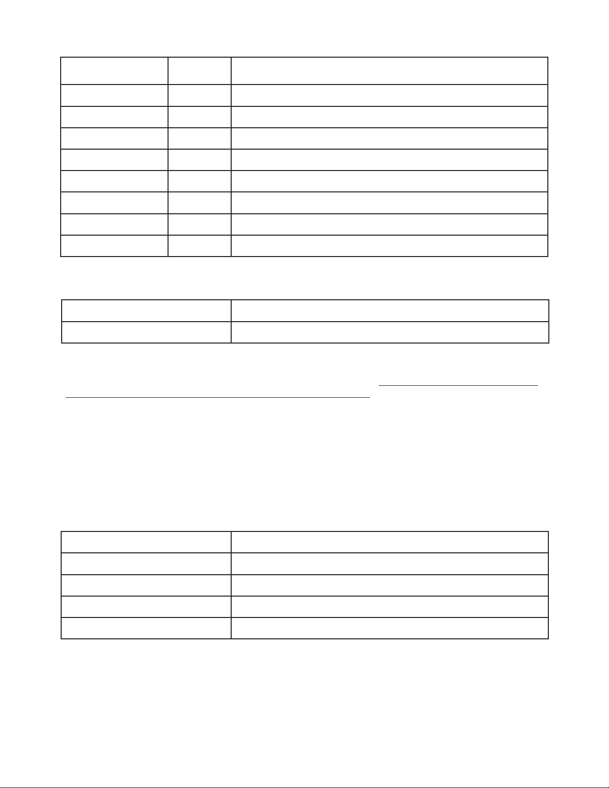
5.1.2 Pumps
Parameter
SAMPLE FLO RUN 1,000 Sample flow rate during the RUN cycle.
SAMPLE FLO PRI 2,086 Sample flow rate during in the PRIME mode.
SAMPLE FLOW STBY 2,086 Sample flow rate in STANDBY mode.
SAMPLE FLO RINSE 2,086 Sample flow rate in the RINSE mode.
REAG FLOW RUN 25 Reagent flow rate during the RUN cycle.
REAG FLO PRIME 400 Reagent flow rate during the PRIME cycle.
REAG FLO STBY 40 Reagent flow rate during the STANDBY mode.
REAG FLO RINSE 80 Not used. Reagent pump is OFF during RINSE.
Time
(seconds)
Explanation
5.1.3 LEDs
LED SETTING (SELECTION) Default Setting
GREEN LED POWER % (18) for 3017M
NOTE: The 3017M has three LED’s; green, blue and red. Only one of those wavelengths is used at any
given time. The selection of the wavelength is application dependent. The selection of wavelength, or the
LED Power setting should not be changed under any circumstances.
5.2 Setup
The setup menu contains important settings that can be used to configure the 3017M for Modbus control, or other
control systems. These settings are mainly found under COMMUNICATIONS and 4-20 mA SETUP. The settings listed
are the default settings.
5.2.1 Communications
Parameter Explanation
Baud Rate 9600
Modbus Address 1
Mode ASCI/RTU RTU
Modbus Local Control MODBUS IS AVAILABLE
Default Configuration & Method Settings
37
Page 39

5.2.2 4-20 mA Setup
Parameter Explanation
DAC Counts for 4 mA SET DAC = 28E9 CNTS
DAC Counts for 20 mA SET DAC = CC3D CNTS
4 mA Cl Equivalence 4 mA SET = 0.000 mg/L
20 mA Cl Equivalence 20 mA SET = 5.000 mg/L
Mid-Range Test See below
NOTE: The DAC counts shown above are the default values. The 4 and 20 mA outputs are not adjusted at
the factory as part of the checkout procedure. The DAC count values are different than the default values
for every instrument. The Mid-Range test value will depend on the adjustment of the 4 and 20 mA output
settings.
5.3 Status
The items available for viewing under status are covered in Section 4 and will not be covered in detail in this section.
However, the information provided under status is very important if troubleshooting is necessary.
5.4 Linearization
The entries under linearization allow for field calibration of the 3017M, field linearization of the 3017M and viewing of
the calibration gain. The 3017M is linearized and calibrated at the factory as part of the checkout process; therefore,
each analyzer will have a unique set of linearization coefficients. In most cases, it is not necessary to recalibrate, or relinearize, the 3017M. A complete procedure for linearization will be covered in the maintenance section, Section 6.
5.5 Maintenance
There are no default settings for the command under maintenance except for ENGINEERING ACCESS. The default
value for ENGINEERING ACCESS is (15). This must be set to (19) to gain access to all other settings.
38
Default Configuration & Method Settings
Page 40

6. Maintenance
WARNING The processes and procedures in this section involve handling chemicals. Only qualified
personnel should conduct the tasks in this section.
WARNING The processes and procedures in this section involve working with electrical circuits.
Only qualified personnel should conduct the tasks in this section.
6.1 Regularly Scheduled Maintenance
6.1.1 Reagent Replacement
The buffer and indicator reagents last approximately one month. New containers will accompany the reagent kits, part
number 330006 and 330007, and should be used for the new reagents. Discard the old containers. Install the new
containers as outlined below.
The REAGENT LIFETIME TIMER should have been set to the desired time; usually between 30 – 40 days. If the time has
expired, a warning will be flashing on the HOME screen. Navigate to the MAINTENANCE screen, and select:
CLEAR ALARMS & TIMERS.
6.1.2 Pump and Reagent Tube Replacement
The sample and reagent pump tubes will deteriorate over a period of time due to the action of the peristaltic pump
rollers and the pressure of the platens. The recommended replacement interval is six months.
Replacement Procedure
1. It is not necessary to shut off sample flow at the Sample
Inlet Device or disconnect power to the analyzer.
However, the analyzer should be in the SHUTDOWN
mode to prevent rotation of the sample and reagent
pumps that normally occurs in the STANDBY mode.
2. Remove the cover of the sample pump. Disconnect the
sample inlet and waste lines at the barb fittings. Retain
the barb fittings for transfer to the new sample pump
tube. See Figure 6.1 for installation of the new sample
pump tube.
3. Position the tube so that it connects so that the barb
fittings on each end are even; they will be adjusted in a
later step.
4. Locate the package of silicone lubricant and cut a small
opening across one corner of the package.
5. Apply a thin layer of the silicone lube to the section of
the tube that will mount on the roller in the pump. A
small bead of approximately 3-mm in diameter should
be sufficient. Spread the lube along the section of the
tube that will contact the pump tube rollers. Do not
apply the lube in excess. There is sufficient lubricant
in the startup kit for multiple pump tube installations.
Remove any excess.
6. Hold the pump tube over the roller, and gently push the
roller onto the drive shaft of the pump motor.
Figure 6.1 Positioning of sample pump
tube in sample pump
Maintenance
39
Page 41

Figure 6.2 Completed pump tube installation
7. Refer to Figure 6.2.
8. Snap the cover into place so that the roller stays in place.
9. Gently pull the sample tube back and forth so that the ends
with the barb fittings are even with each other.
10. Install the sample inlet tube to the left-hand side barb fitting
on the sample pump. Connect the right-hand-side barb fitting
to the line from the sample pump to the flowcell.
11. Disconnect the buffer and indicator pump tubes from the
flowcell and the reagent bottles. Relieve the pressure on the
reagent pump platens by pushing up on the tensioners. Refer
to Figure 6.3.
12. Release the platens on the reagent pump by pulling back on
the tabs that extend at the top and gently pulling downward
on the platens. Discard the old reagent pump tubes.
13. Locate the replacement pump tubes. There are two tubes; one
for the buffer and one for the indicator.
14. Hold a pump tube so that the locking tab (blue tab) is in your
left hand. Attach the end in your right hand to the reagent port
marked (B). This will be the port closest to the right-hand-side
of the enclosure.
15. Route the tube through an empty cassette, placing the locking
tab on the tubing against the left outer edge of the cassette,
and then snap it into place in the rear slot.
16. Attach the free end to the barb fitting on the buffer reagent
container.
17. Repeat the three steps above (14, 15, and 16) for the indicator
reagent tube. The indicator platen/tube will go in the front slot.
18. Tension the platens by pushing down on the tensioners. The
tensioners will make an audible “click”. Typically, three “clicks”
is sufficient tension on the pump tube.
19. See Figure 6.4.
20. This completes the installation of the reagent pump tubes.
Figure 6.3 Installation of buffer reagent tube
Priming the Tubes
The new tubes must be primed with liquid, sample and
reagent before the analyzer is returned to normal operation.
Prime the tubes as follows:
1. From the HOME screen, use the UP/DOWN buttons
and navigate to the PRIME > ENTER.
2. Observe the waste line from the flowcell and once the line
is free from bubbles, the lines are primed with liquid.
3. Select: STANDBY > ENTER. Pump rotation will cease.
Inspect all connections for leaks, and if none are found,
proceed to step 4.
4. Select: STARTUP > ENTER. The analyzer will begin
normal operation.
40
Figure 6.4 Completed reagent tube
installation and platen tensioning
Maintenance
Page 42

6.1.3 Flowcell Cleaning
The colorimeter measuring cell may develop a film from the growth of biological material or from the reagents over
time. Cleaning with a concentrated bleach solution should be all that is necessary to remove this material. The 3017M
has shown to not be susceptible to build-up of this nature for as long as 150-180 days. If the output of the 3017M
falls outside of the validation checks, then this may indicate the need for measuring cell cleaning. See Section 7,
Troubleshooting for a more complete description on this.
CAUTION Chemical exposure hazard. The chemicals used in this procedure may be hazardous if
inappropriately handled or accidentally misused. Protective eyewear is always recommended when
contact with chemicals is possible. Follow all precautionary instructions on the labels.
Measurement Cell Clean Procedure
1. Regular, household bleach, like Clorox®, is all that is necessary for measurement cell cleaning.
2. It is not necessary to remove power from the instrument. Using the keypad, place the instrument in SHUTDOWN
mode to prevent rotation of the pumps.
3. Using the syringe assembly that is provided with the analyzer, fill the syringe with 10-mL of full-strength bleach.
4. Remove the plug on the cleaning port and attach the fitting on the end of the tube connected to the syringe
assembly.
5. Slowly inject 7-8 mL of the cleaning solution, leaving a small amount in the syringe. The liquid will flow through the
measurement cell and into the waste line. Do not remove the syringe assembly.
6. Allow the solution to sit in the measurement cell for 5 minutes.
7. Gently pull the cleaning solution that had been injected in Step 5 back into the syringe. Disconnect the syringe
from the tubing at the Luer fitting. Discard the dirty cleaning solution and thoroughly rinse the syringe assembly by
pulling 5 full syringe volumes of DI Water and discarding each syringe volume.
8. Fill the syringe with DI Water and gently push the water through the measurement cell. Repeat this step 5 times.
9. Disconnect the cleaning assembly at the flowcell cleaning port, and reinstall the plug.
10. Using the process sample, place the instrument in the RINSE mode. Use the UP or DOWN arrows and toggle to the
RINSE command. Press ENTER. Allow the analyzer to rinse with the process sample for 10 minutes.
11. Toggle to STARTUP and press ENTER.
6.2 Unscheduled Maintenance
6.2.1 Fuse Replacement
DANGER Electrocution hazard. Remove power from the instrument when removing or installing
the fuse.
DANGER Fire hazard. The replacement fuse must be of the same type and rating. A spare fuse can be
found in the analyzer Startup Kit.
Maintenance
41
Page 43

Fuse Replacement Procedure
1. Ensure that the replacement fuse is: 5x20mm, 500mA, 250V. This fuse can be used for both 115VAC and 230VAC
operation.
2. Disconnect the mains power at the source: outlet, switch, circuit breaker, or any other device.
3. Locate the fusible link on the terminal block and gently pull it open. Refer to Section 2, Figure 2.8.
4. The fuse is located inside the fusible link. Open the cover of the link and the fuse will be rejected by the fuse
holder clips. Remove the fuse.
5. Insert one end of the new fuse into the clip and push down to secure the fuse in the clip. Close the cover and the
fuse will snap into place.
6. Close the fusible link and restore power at the source.
6.2.2 Linearization
The 3017M is linearized at the factory and the results verified at the factory before shipment. Under normal
circumstances, it should not be necessary to re-linearize the analyzer. The decision to re-linearize the analyzer should
be made in consultation with Technical Support. There may be other means to solve an apparent issue with the
linearization without following this procedure. Some guidance is provide in Section 7, Troubleshooting.
Linearization Coefficients
There are three linearization coefficients for the 3017M: A-COEF, B-COEF, and C-COEF. These coefficients are stored
under the LINEARIZATION menu. These coefficients are also recorded at the factory for each 3017M and are stored
by the serial number of the analyzer. If you have a question as to the correct value of the coefficients, contact Technical
Support and verify them. This may eliminate the need for re-linearization of the analyzer.
NOTE: The linearization coefficients should not be arbitrarily changed, under any circumstance, as incorrect results will
be obtained by the 3017M. If for some reason, the linearization coefficients differ from what is recorded at the factory,
the correct value can be entered after consultation with Technical Support.
NOTE: Record the current linearization coefficients for reference before starting this procedure.
The linearization coefficients are determined by analyzing a series of very well defined standards. Under
LINEARIZATION, these are designated as: LOW LINEAR STANDARD, MED LINEAR STANDARD, and HI LINEAR
STANDARD. The 3017M firmware will determine each of the coefficients after the results of the three standards are
recorded.
6.2.3 Field Linearization Procedure
NOTE: Certain settings on the 3017M will be changed during this procedure. It will be necessary to UNLOCK the
analyzer to modify these settings. Navigate to: MAINTENANCE > ENGINEERING ACCESS and enter the passcode, 19.
Preparation of Linearization Standards
All steps of the field linearization process are important and one of the most critical steps is the preparation of
the three standards. Reasonable care and good laboratory practices should be followed in the preparation of the
standards.
The range of the 3017M is 0 – 5 mg/L. The standards that will be used to linearize the analyzer will need to be within
this range. The typical values for linearization standards are: zero (0), 1.5 – 2.5 mg/L and 4.0 – 5.0 mg/L. Never exceed
the maximum range of the analyzer.
All glassware has some chlorine demand; therefore, glassware must be conditioned with chlorine before it is used
to prepare standards. Prepare three, 1-L containers by adding 1-mL of household bleach and filling the container to
overflowing. Cap the container and allow it sit for a period of several hours. After this conditioning period, thoroughly
rinse each container with chlorine-free water that will be used to prepare the standards. DI Water is preferred but not
absolutely necessary. Fill each container with the water that will be used to prepare the standards, and determine if
there is any chlorine residual. Rinse as many times as necessary.
42
Maintenance
Page 44

NOTE: Very often, DI Water systems are sanitized with sodium hypochlorite (bleach). Therefore, it is possible that these
systems may have a low-level residual chlorine level. Make a determination with a handheld meter, or some other
technique to verify that the water used in this procedure is chlorine free.
The water that was used to rinse the three containers will be the water used for the zero (0) linearization standard.
Prepare the other two standards in the range listed above and verify the concentration with a secondary technique.
Allow the standards to sit for 24 hours. Re-verify the concentration and adjust as necessary.
NOTE: Chlorine concentration can decrease slowly, over time, after the initial preparation. The linearization will be
affected if the chlorine standard is slowly decreasing in value while the 3017M is analyzing a standard.
Once the chlorine concentration of the linearization standards have been verified, it will be necessary to enter these
values for each of the three linearization standard entries: LOW LINEAR STANDARD, MED LINEAR STANDARD, and HI
LINEAR STANDARD.
Entering the Linearization Standard Values
1. Navigate to LINEARIZATION. Use the UP or DOWN arrows and navigate to: LOW LINEAR STANDARD. Press Enter.
The default value should be zero (0). Follow the prompts on the screen to enter the correct value. The screen will
display the previous menu after entry.
2. Use the DOWN arrow to navigate to: MED LINEAR STANDARD. Follow the same procedure as in Step 1.
3. Use the DOWN arrow to navigate to: HI LINEAR STANDARD. Follow the same procedure as in Steps 1 and 2. At this
point it would be prudent to verify each entry for the three linearization standards.
Analyzing the Linearization Standards
1. Depending on the location site of the 3017M, it may be necessary to position a table, cart, or some other sturdy
and flat surface upon which to rest the linearization standards. Access to the sample inlet fitting on the bottom of
the enclosure will be necessary.
2. If the 3017M is running, place it in SHUTDOWN. Disconnect the sample line at the bottom of the enclosure and
attach a section of 1/8-inch OD, Teflon® tubing. The length of the tubing should not exceed 1 m (3.25-ft). If you do
not have this tubing, contact Technical Support and it can be provided for you.
3. Analyze the standards in order of increasing concentration. Place the zero linearization standard, LOW LINEAR
STANDARD in position. From the keypad, place the 3017M in the RINSE mode. Rinse the sample pathway until the
sample pathway is free of air bubbles.
4. Once the sample pathway is thoroughly rinsed, press: STARTUP. It is not necessary to exit from RINSE. The 3017M
will move immediately to STARTUP.
5. After the STARTUP sequence, the 3017M will begin the analysis of the sample. Allow the instrument to make at
least five (5) measurements.
6. While the last result is being displayed and before the next measurement, navigate to: LINEARIZATION >
LINEARIZATION TASK > LINEAR TASK LO. Press the UP button to LOCK the last result. This will lock the absorbance
value that is associated with this standard.
7. Place the instrument in SHUTDOWN. Remove the LO LINEAR STANDARD and position the MED LINEAR
STANDARD. Enter: PRIME and allow the MED LINEAR STANDARD to fill the sample path way and ensure that all
bubbles have been removed from the sample path way. Select: STARTUP.
8. While the last result is being displayed and before the next measurement, navigate to: LINEARIZATION >
LINEARIZATION TASK > LINEAR TASK MED. Press the UP button to LOCK the last result. This will lock the
absorbance value that is associated with this standard.
9. Place the instrument in SHUTDOWN. Remove the MED LINEAR STANDARD and position the HI LINEAR
STANDARD. Enter: PRIME and allow the HI LINEAR STANDARD to fill the sample path way and ensure that all
bubbles have been removed from the sample path way. Select: STARTUP.
10. While the last result is being displayed and before the next measurement, navigate to: LINEARIZATION >
LINEARIZATION TASK > LINEAR TASK HI. Press the UP button to LOCK the last result. This will lock the absorbance
value that is associated with this standard.
Maintenance
43
Page 45

11. Use the DOWN arrow to select: RE-LINEARIZE. Once this selection is made the following screen will be displayed.
See below. If the data check passed has passed all criteria, use the UP button to recalculate the linearization
coefficients. If the data check did not pass, then it will be necessary to repeat this procedure. See Figure 6.5.
BACK
DATA CHECK:
DATA PASSED CHECK
PRESS UP BUTTON TO
RECALCULATE COEF
ENTER
Figure 6.5 3017M display screen with data check pass
12. Place the instrument in SHUTDOWN. Remove the HI LINEAR STANDARD and position the MED LINEAR
STANDARD. Enter: PRIME and allow the MED LINEAR STANDARD to fill the sample path way and ensure that all
bubbles have been removed from the sample path way. Select: STARTUP.
13. The reported value for the MED LINEAR STANDARD should be within acceptable variance. If it is not within
acceptable variance, it may be necessary to recheck the concentration of the chlorine standards and repeat this
process. It would be advisable to contact Technical Support.
14. Upon completion of this procedure, navigate to: METHOD > METHOD SAVE RESTORE > SAVE CURRENT
METHOD. Failure to take this step will result in the loss of the newly determined coefficients in the event of a
power cycle.
44
Maintenance
Page 46

7. Troubleshooting
7.1 Basic Guide
Symptom Cause Corrective Action
Display does not light, the pumps do
not operate and cooling fan is not
audible.
Display does not light but the pumps
operate and fan is audible.
Display lights, fan is audible, but the
pump, or pumps, do not operate
Air bubbles in the line leading to the
flowcell.
Check the external switch or breaker,
No power to the analyzer.
Loose connection on the control
board or issue with the control board.
Incorrect (low) line voltage.
Loose connection at the main control
board for either pump.
Defective power supply Replace power supply.
Defective main control board Replace main control board.
Sample is not present at the sample
pick-up line.
Reagents are empty. Replace reagents.
Reagent pump platens are not properly tensioned.
Sample or reagent tubes are worn or
damaged.
connections at the terminal block,
ensure the fusible link is fully closed,
and the fuse is not blown.
Check connector from display to
main control board. Replace main
control board.
Measure line voltage at the terminal
block.
Check connector(s) for affected
pump, or pumps.
View the clear tubing on the Sample
Inlet Device (if installed). Liquid
should be visible.
Check for the presence of sample in
any other device or sample point.
Check for clogged tubing or screen.
Tension the pump platens by three
“clicks” from the released position.
Refer to Section 3 of the manual.
Check sample and reagent tubes for
wear and replace, if necessary.
Maintenance
Loose fittings Check that all fittings are tight.
Sample and reagent tubes were not
properly primed after service.
Table 1 Basic troubleshooting steps for the analyzer
Select PRIME from the main menu
and fill lines with sample and reagents.
45
Page 47

Symptom Cause Corrective Action
Bubbles in the flowcell. See above.
Check reagent levels.
Sample is flowing but reagents are
not flowing.
Zero Reading
No chlorine in sample.
Reagents are flowing but sample is
not flowing.
Clogged sample tubing or screen (if
installed).
Worn pump or reagent pump tubes. Replace tubing.
Low Reading
Erratic Reading Air bubbles in the optical cell.
Weak or improperly prepared reagents.
Dirty flowcell Clean flowcell.
Disconnect buffer, and/or, indicator
tube at flowcell. Reagent should drip
each tube. If not present, see below.
Check tension on reagent pump
platens.
Verify that sample has chlorine with
grab sample measurement.
Replace tubing.
Replace reagents.
Use all of the recommended tips in
the Air bubbles in the line leading to
the flowcell symptom above.
Negative Drift Weak reagents. Replace reagents.
Positive Drift Dirty optical cell Clean optical cell
Table 1, cont’d Basic troubleshooting steps for the analyzer
7.2 Using the Manual Controls and STATUS
Screen for Troubleshooting
In Section 4, the User Interface and all of the Tiers in the firmware were described in detail. The various functions and
status screens that are available to the User can be very helpful for troubleshooting purposes. The items below list
some of the more common uses.
7.2.1 No Sample or Reagent Flow
RINSE Function
If the instrument is running, place it in SHUTDOWN: Press ENTER > SHUTDOWN. Use the UP and DOWN arrows
and navigate to RINSE. Press ENTER. The sample pump will rotate and attempt to pull sample from the process
connection, or any container that is connected to the sample line.
Observe the line from the sample point; it should be filled with liquid. If it is filled with liquid, follow the flow path and
disconnect at various points to determine where flow is lost. If the line is not filled with liquid, or if it is partially filled,
and the liquid moves, back and forth, but does not advance up the tube, the sample pump tube should be replaced.
PRIME Function
If the instrument is running, place it in SHUTDOWN: Press ENTER > SHUTDOWN. Use the UP/DOWN arrows and
navigate to PRIME. Press ENTER. will rotate and attempt to pull sample from the process connection, or any container
that is connected to the sample The sample pump and reagent pump line, as well as, reagents from the reagent
containers. If the sample has chlorine, the liquid from the exit of the measurement cell should be pink in color. This may
be difficult to discern for low chlorine concentration.
46
Troubleshooting
Page 48

If sample flow has been established and confirmed, using the previous step, disconnect the buffer and indicator tubes
at the flowcell. Buffer and indicator solution should be visible at each of these connections. If no liquid is visible, check
the container for reagent level and clogging of the reagent bottle dip tube. Check the tension on the reagent pump
tensioners, but do not exceed the recommended tension. Refer to Section 2. If the reagent level is sufficient, the dip
tube is free of obstruction, and not flow is present, replace the reagent pump tubes. Always replace them as a set.
7.3 Using Tier 3 Selections Under STATUS
for Troubleshooting
The STATUS menu in tier 3 has various selections that can be used for troubleshooting purposes. The settings in each
of these entries are nonadjustable. A complete listing and description of the items in this tier is listed in Table 2. A brief
explanation is given on how each item could be helpful in troubleshooting.
Option Description
Refrnc VDC The instantaneous voltage seen at the A/D convertor from the reference channel.
Sample VDC The instantaneous voltage seen at the A/D convertor from the sample channel.
The gain setting for the reference channel. (1) is the lowest setting and (8) is the high-
Ref
Sam
est setting. The number to the right of the Gain Setting can be used to monitor the gain
change.
The gain getting for the sample channel. (1) is the lowest setting and (8) is the highest
setting. The number to the right of the gain setting and can be used to monitor the gain
change.
L The low linearization sample and its absorbance.
H The high linearization sample and its absorbance
M The medium linearization sample and its absorbance
C The calibration sample and its absorbance
Liquid Lvl Sensor The liquid level sensor status: 1 is tripped, 0 is not tripped
Error The error status: 1 is showing an error flag, 0 is not showing an error flag
Firmware The two-letter code is the firmware revision, ex. DZ.
PCA The PCA revision level.
Compiled The compile date of the firmware.
Table 2 Tier 3 selections under the STATUS menu. These are nonadjustable settings
and used as references for troubleshooting purposes
Troubleshooting
47
Page 49

7.3.1 Main STATUS Screen
An example of the main STATUS screen is shown in Figure 7.1. The values in this figure are representative of the values
that will be found on a 3017M; however, the exact values will be different for every instrument. This screen displays the
following values from Table 1: Reference VDC, Sample VDC, Ref (Reference Gain), and Sam (Sample Gain).
BACK
Reference VDC 3.260
Sample VDC 3.018
Ref 1 019929.1
Sam 1 013576.5 0
ENTER
Figure 7.1 An example of the main STATUS screen
Reference VDC
As explained in Table 1, the reference VDC is the instantaneous voltage at the A/D converter for the reference channel.
This voltage is typically in the range of 2.50 V to 3.50 V. The voltage reading on the reference channel is not affected
by sample flowing through the flowcell; however, the voltage on the reference channel should be comparable to
the voltage on the sample channel when clean, reagent-free water is flowing through the flowcell, but the voltages
will not be identical. Instability on the reference channel can only be caused by some issue with the LED, reference
photodiode, or the light guide that transmits light from the LED to the photodiode. If this voltage is outside of these
values, the results could be affected, and you should contact Technical Support. A voltage of 0.5 V, or lower, indicates
that the LED or photodiode is not working.
Sample VDC
As explained in Table 1, the sample VDC is the instantaneous voltage at the A/D converter for the sample channel.
This voltage is nominally in the range of 2.50 V to 3.50 V. The voltage reading on the sample channel is affected by the
intensity of the color change from the reaction of DPD with the chlorine in the sample flowing through the flowcell.
As the intensity of the color changes, the voltage will decrease. At the INTEGRATION step in the instrument cycle, the
voltage output should be very stable. The sample voltage may go lower than 2.50 V, if the chlorine concentration in the
sample is at, or above, the maximum range of the analyzer. If this voltage is outside of these values, the results could be
affected, and you should contact Technical Support. A voltage of 0.5 V, or lower, indicates that the LED or photodiode
is not working.
Ref (Reference Gain)
The electronics and control firmware of the 3017M is constantly monitoring, and adjusting, if necessary, the gain
setting on both the reference and sample channels. The number after “Ref” is the gain setting. For the reference
channel, this number is typically 1, or possibly 2. The number to the right of the gain setting is the actual Analog-toDigital converter (A/D) counts for the reference channel. This number should be between 32K and 15K counts. If for
some reason, the output of the A/D cannot reach 15K counts, the gain setting will be increased to the next highest
setting. The only factors that will affect the reference gain setting is the LED output, the condition of the fiber optic
pathway between the LED and the photodiode, the photodiode, and temperature. A LED will become more efficient at
lower temperatures; therefore, a change in the Reference counts, and possibly, the gain setting could be observed at
low temperatures. Conversely, a LED becomes less efficient at high temperature.
48
Troubleshooting
Page 50

Sam (Sample Gain)
The electronics and control firmware of the 3017M is constantly monitoring, and adjusting, if necessary, the gain
setting on both the reference and sample channels. The number after “Sam” is the gain setting. For the sample
channel, this number is typically 1, or possibly 2, but it could go as high as eight (8). The number to the right of the
gain setting is the actual Analog-to-Digital converter (A/D) counts for the reference channel. This number should be
between 32K and 15K counts. If for some reason, the output of the A/D cannot reach 15K counts, the gain setting
will be increased to the next highest setting. The same factors that can affect the reference channel; LED output, the
condition of the fiber optic pathway between the LED and the photodiode, the photodiode, and temperature can
affect the sample channel. A LED will become more efficient at lower temperatures; therefore, a change in the sample
counts, and possibly, the gain setting could be observed at low temperatures. Conversely, a LED becomes less efficient
at high temperature. If the reference gain setting reaches a value of eight (8), it would be advisable to contact
Technical Support.
The output and gain setting of the sample channel is also greatly affected by the condition of the measurement cell. It
can be expected that the measurement cell will become dirty over time from possible biological growth on the walls of
the cell, or staining from the DPD reaction products. In the normal course of operation, it can be expected that the gain
setting will increase over time. If the gain setting reaches a value of eight (8), then some maintenance action would
be necessary. In most cases, this would be cleaning of the measurement cell. If cell cleaning does not result in a lower
sample gain setting, it would be advisable to contact Technical Support.
Countdown Timer
In Section 3, Analyzer Startup, the STARTUP sequence was explained and the steps in that sequence defined. As part of
the STARTUP sequence, there is a step, AUTOGAIN SET. At this point in the STARTUP sequence, sample that is free of
reagent is flowing through the measurement cell. The A/D counts for both reference and sample are being monitored,
and if a gain change is necessary, it is made during this time.
A change in the gain does not result in an immediate change in the output. Therefore, a COUNTDOWN TIMER is
initiated. This is the number zero (0) in the lower-right-hand corner of the STATUS screen. The gain change is made,
and the slowly starts to rise, while the timer counts down from 10. If at the end of ten seconds, the value of the
geference and sample output has not reached the 15K minimum criteria, the counter resets, and the countdown starts
over. Once the minimum value, or some number above the minimum value, is reached the counter will stop. If the
timer appears to be stuck in an endless loop, it would be advisable to contact Technical Support.
7.3.2 Liquid Level Sensor and Error Levels
Liquid Level Sensor
A liquid level sensor is not used on the 3017M. Therefore, it can be disregarded.
ERR 1-4 (Error Levels and MODBUS register)
The 3017M has four levels of errors and a MODBUS register assigned to that error. The WARNINGS and ERRORs that
will be displayed on the HOME screen are listed in Table 3. The four levels of Errors are described as follows:
ERR 1
This is a fatal error. This error is usually the result of a processor failure, or the failure of some other critical electrical
component. A failure of this type will prevent the operation of the instrument. Call Technical Support.
ERR 2
This is an error that may immediately affect the analyzer results. The analyzer will operate; however, it would be
advisable to contact Technical Support in some cases. Refer to Table 2.
ERR 3
This is an error that may not immediately affect the analyzer results; however, if left unattended, the analyzer results will
ultimately be affected.
ERR 4
These are WARNINGS. WARNINGS will self-reset once the condition causing the WARNING clears.
Troubleshooting
49
Page 51

Warrning
Level Cause Corrective Action
or Error
ERROR: ADC 1 An A/D failure. Call Technical Support.
ERROR: FLASH/
ADDRESS
ERROR: MATH OR
FLOAT
ERROR: SELF TEST 2 System did not pass Self-Test. Call Technical Support
ERROR: DATA
OVERRANGE
WARNING:
REAGENTS OLD
ERROR: AUTOGAIN 3
ERROR:
CALIBRATION
ERROR:
LINEARIZATION
1 A Processor failure. Call Technical Support
1 A Processor failure. Call Technical Support
Navigate to MAINTENANCE < METHOD SAVE
RESTORE. Select: SAVE CURRENT METHOD
< ENTER. Navigate to STATUS. Ensure that the
A continuous bad data reading.
2
2
3
3
Either a bad A/D reading or
bad linearization/gain settings.
The reagents have been in
service more than seven
(7) days past the REAGENT
LIFETIME setting.
The instrument was unable to
correct itself using autogain.
It usually means that the cell
needs to be cleaned, or the cell
is broken or there is a bubble
in the cell.
The instrument could not
generate a good calibration.
This could happen during field
calibration if the standard is not
the proper concentration or
the flowcell is compromised.
The instrument could not
generate a good Linearization.
Either the standards were
analyzed in the incorrect order,
or the flowcell is compromised.
values are in the range as described in Section
7.3.1. If the values are not in the proper range,
navigate back to METHOD SAVE RESTORE and
select: DEFAULT METHOD 3017. If the values
are in the proper range, it will be necessary to
contact Technical Support to obtain the correct
linearization coefficients.
Replace the reagents. Navigate to CLEAR ALARMS
AND TIMERS under MAINTENANCE and clear the
error. A new timer for REAGENT LIFETIME will be
set.
Inspect the flow path from the sample tap to the
flowcell for the presence of bubbles. If bubbles
are present, correct the cause. If bubbles are not
present, follow the cleaning procedure in Section
6. If cleaning does not correct the issue, remove
the optical cell exit fitting and extract the flowcell
glass. See Section 8. If the Flow cell glass is
broken, replace it.
Ensure that a value for the calibration standard
has been entered under: LINEARIZATION <
calibration standard. If a value of zero (0) is
entered for the calibration standard, this will also
cause the error. Refer to the corrective action
under ERROR AUTOGAIN and follow these steps if
necessary.
Repeat the process and ensure that the standards
are the proper value and are analyzed in the
proper order. Refer to the corrective action under
ERROR: AUTOGAIN and follow these steps if
necessary.
50
Table 3 List of ERRORS and WARNINGS for the 3017M
Troubleshooting
Page 52

Warrning
or Error
ERROR:
TEMPERATURE
WARNING:
TEMPERATURE
WARNING:
REAGENTS OLD
Level Cause Corrective Action
If the analyzer is installed in a location in which
the ambient temperature exceeds the 3017M
specifications, this could cause the error. If
ambient conditions are within specification, the
3
4 Temperature is out of range.
4
The temperature has been outof-range for over 24 hours.
The reagents are within seven
(7) days of the REAGENT
LIFETIME SETTING.
Table 3, cont’d List of ERRORS and WARNINGS for the 3017M
thermoelectric cooler assembly will need to be
checked for proper operation. Ensure that external
cooling fan is ON and turning, place your hand on
the cold finger (metal plate against the indicator
bottle) and determine if it is cold. It should be cold
to the touch. If the cold finger is not cold, the TEC
assembly will need to be serviced.
See the corrective action for ERROR:
TEMPERATURE
Change the reagents within seven (7) days or an
ERROR will be displayed at the end of seven (7)
days.
7.3.3 Firmware and PCA Revision Levels
The information on this screen is for reference only. It may be necessary to have this information available to Technical
Support for assistance with troubleshooting.
Troubleshooting
51
Page 53

8. Parts and Accessories
The parts and accessories for the 3017M Chlorine Analyzer are listed on the following Illustrated Parts Breakdowns.
Part # Description
332266 MODEL-3017M DPD CHLORINE ANALYZER YSI
1
2
3
Parts List
Item # Part # Qty U/M Description
1 332100 1 EA 3017M MANUAL - YSI
2 332189 1 EA FRONT COVER, ENCLOSURE
3 327114 1 EA SAMPLE INLET DEVICE
52
Parts and Accessories
Page 54
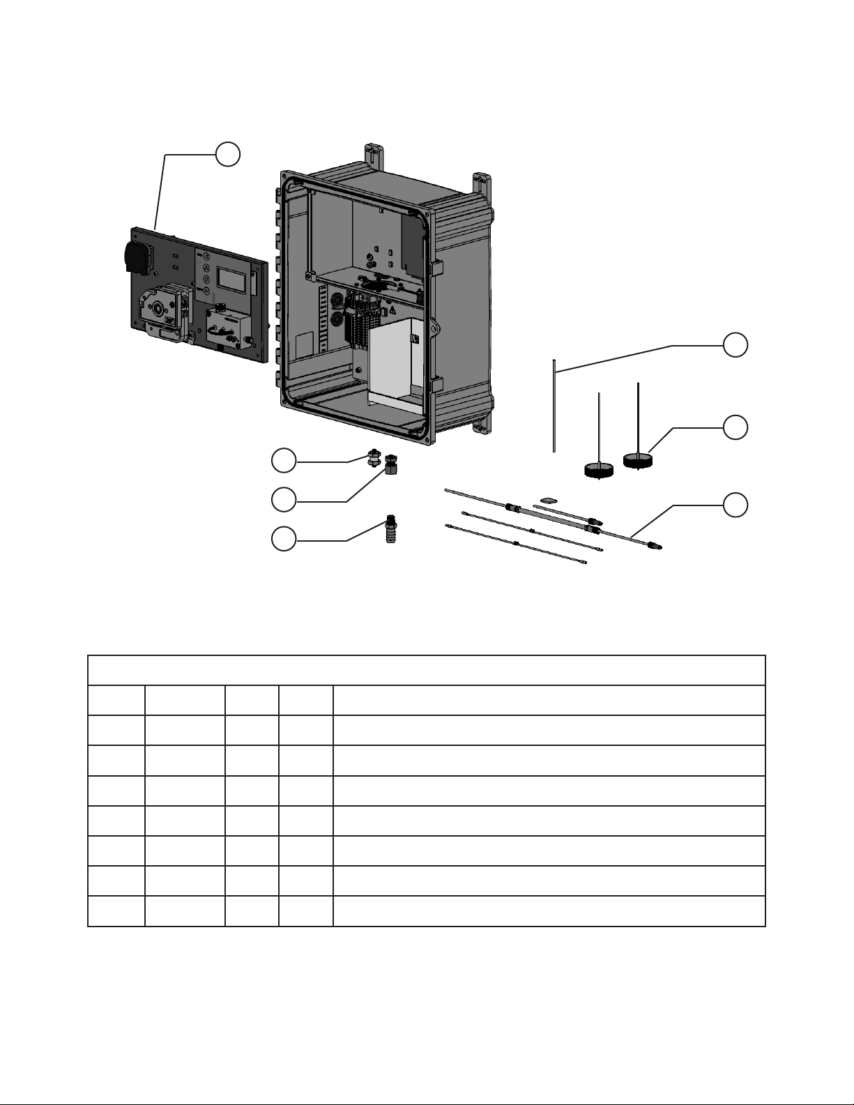
1
7
6
2
3
4
Parts List
Item # Part # Qty U/M Description
1 332096 1 EA 3017M MEASURING UNIT ASSEMBLY
2 332198 1 EA PUSH TO CONNECT FITTING, BR/NI 1/8” X 1/8”
3 332199 1 EA THROUGH WALL FITTING, BR/Ni 1/8” PUSHLOK TO 1/4”FMNPT
4 332182 1 EA BARBED FITTING, NYLON, DRAIN
5 332263 1 EA KIT - 3017M SPARE TUBING KIT
6 332270 1 EA REAGENT CAPS, 2 EACH
5
7 147901 72 IN TUBING-PTFE 1/8 X .062 INCH INNER DIAMETER, CLEAR, 3017M
Parts and Accessories
53
Page 55

1
2
2X
5
3
Parts List
Item # Part # Qty U/M Description
1 330773 1 EA SAMPLE PUMP, INCLUDES COVER AND ROLLERS
2 330842 1 EA REAGENT PUMP ASSEMBLY
3 329813 2 EA CLAMP-HALF P-CLIP .250 STEEL
4 332175 1 EA MEASUREMENT FLOW CELL, COMPLETE ASSEMBLY
5 330420 1 EA MAIN CIRCUIT BOARD, PROGRAMMED
Parts List
Item # Part # Qty U/M Description
1 332259 1 EA COVER-3017 SAMPLE PUMP
4
54
Parts List
Item # Part # Qty U/M Description
1 332260 1 EA ROLLERS - 3017 SAMPLE PUMP
Parts List
Item # Part # Qty U/M Description
1 332258 1 EA PLATEN CASSETTE STYLE REAGENT LEVER PUMP
Parts and Accessories
Page 56

1
3
4
5
2X
6
6
Parts List
Item # Part # Qty U/M Description
1 332172 1 EA FITTING, OPTICAL CELL DRAIN, STAINLESS STEEL
2 332269 1 EA GLASS FLOW CELL WITH O-RINGS
3 332079 1 EA SAMPLE FLOW CELL ASSEMBLY LENS
4 332090 1 EA ASSY-3017M CELL W/POTTED LIGHT GUIDES
5 332085 1 EA MIXER-3017M OPTICAL CELL, EACH
6 332075 2 EA FITING ASSEMBLY, REAGENT JET .005 INCH, 1 EACH
7 A000267 2 EA CLEANING PORT PLUG
Parts and Accessories
55
Page 57

1 2X
2
4X
3 2X
Parts List
5
18” X
6
7
2X
8
14.5” X
6
Item # Part # Qty U/M Description
1 324084 2 EA FTNG-NUT CPVC 1/4-28 X 1/8” RV
2 317545 4 EA FREL-TFZL 1/8 FLANGELESS
3 332409 2 EA FTNG-ADPTR 1/4-28 X 3/16” ID BARB
4 332405 1 EA TUBE-3017M SAMPLE PUMP 3/16” ID
5 331121 1 EA LUBE-SILICONE 9017 PUMP TUBING 2GM
6 147901 50.5 IN TUBING-PTFE 1/8 X .062” ID CLEAR
7 319343 2 EA FTNG-NUT PK 1/4-28 1/8 NAT FLS
8 332268 1 EA KIT-3017M REAGENT TUBES
56
Parts and Accessories
Page 58
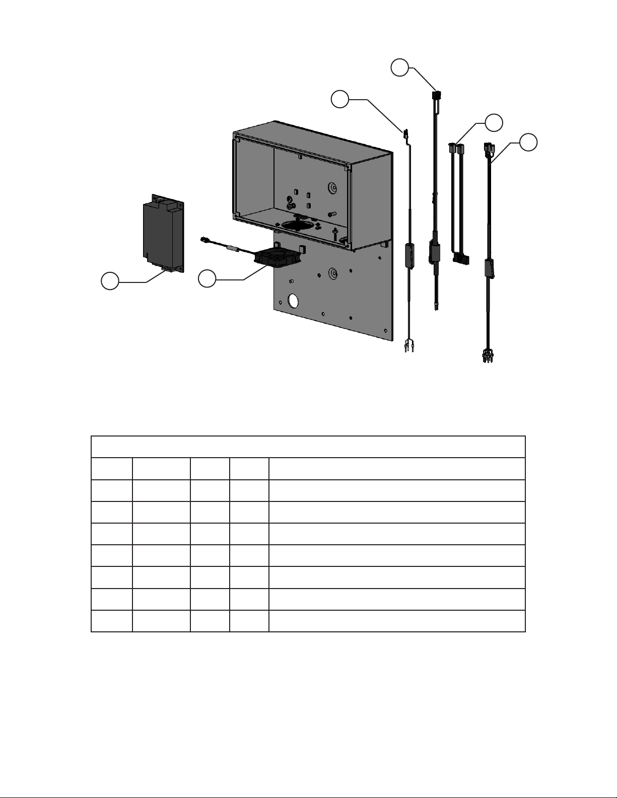
4
3
5
6
1
Parts List
Item # Part # Qty U/M Description
1 328238 1 EA POWER SUPPLY-160W 24VDC 3X5
2 330875 1 EA ASSY-9017 INTERNAL FAN
3 330872 1 EA CABLE-9017 RS485 W/FERRITE, R3
4 330858 1 EA CABLE HARNESS-9017 AC PWR/SWITCH W/FERRITE
2
5 330837 1 EA CABLE-9017 DC FROM PWR SPLY TO MAIN PCA
6 332262 1 EA CABLE-9017M I/O PCF TO DIN
7 A000267 2 EA PLUG-1/4-28 TEFZEL
Parts and Accessories
57
Page 59

2
3
1
5
6
4
Parts List
Item # Part # Qty U/M Description
1 296012 1 EA FILTER-PE 60U
2 332422 1 EA FTNG-PUSHLOCK ACTL 1/4NPT X 1/4”
3 332421 1 EA FTNG-PVC 1/2” MNPT X 1/4” FNPT
4 327112 12 FT TUBING-PVC CLR 1/2” ID X 3/4” OD
5 326376 1 EA ASSY-SAMPLE INLET SYSTEM 9210
6 327385 1 EA CLIP-COMPONENT 1”
58
Parts and Accessories
Page 60

9. Declaration of Conformity
According to ISO/IEC Guide 22 and EN 45014. The undersigned hereby declares that the products listed below
conform to all applicable Essential Requirements of the listed Directives and Standards and carry the CE mark
accordingly.
Manufacturer’s Name YSI, a Xylem brand
Manufacturer’s Address 1725 Brannum Lane
Yellow Springs, OH 45387
USA
Product Name 3017M Chlorine Analyzer
Item Number 332266
Test Report Numbers • 21248-28
• 014279325ATL-001
Directives • RoHS 2011/65/EU
• EMC 2014/30/EU
• EMC EN 61326-1:2013
• EMC CISPR 11:2009+A1:2010
• LVD 2014/55/EU
• EN 61010-1:2010 3rd
• ETL Listed
Quality Manger
20 March 2020Gregory Popp
Part #281519-43S
59
Page 61

Appendix A: MODBUS Manual
MODBUS manual for the 3017M Chlorine Analyzer, Rev EA 08/20.
0xXX Coils (Read/Write)
Number Hex Name Description
1 0x01 Bit Unused Unused
2 0x02 Bit RS489Enabled Enable use of MODBUS RS485
3 0x03 Bit 4-20Enabled Enable use of 4-20 mA output
4 0x04 Bit ClearAlarms Clear all alarms, coil automatically reset
5 0x05 Bit ClearAlarmsAndTimers Clear all alarms and hour/day/month timers,
coil automatically reset
6 0x06 Bit ZeroReading Clear all math and await next reading
7 0x07 Bit ZeroNewResultFlag Clear new result (status 6)
8 0x08 Bit UseAutoGain If set, over-range AD readings will AutoGain
9 0x09 Bit UseCcoef Force cal curve through 0 cleared
10 0x0a Bit Relay1 Activate/clear Relay1
11 0x0b Bit Relay2 Activate/clear Relay2
12 0x0c Bit Use AutoLEDSet AutoSet LEDs on AutoGain fail
13 0x0d Bit TemperatureDisable Turn off controls and alarms (to be used when
cooler not installed)
14 0x0e Bit Abort Force timer to zero
1xXX Status Inputs (Read only)
Number Hex Name Description
1 0x01 Bit Error
2 0x02 Bit Spare
3 0x03 Bit Relay1Active
4 0x04 Bit Relay2Active
5 0x05 Bit StandbymodeFlag
6 0x06 Bit NewResult
7 0x07 Bit IsInAutoGain
8 0x08 Bit StartHit
9 0x09 Bit StopHit
10 0x0a Bit Fault
11 0x0b Bit LiquidLevelLow
12 0x0c Bit IsInAutoLED
60
Page 62

3xXX Input Registers (Read Only)
Number Hex Name Description
1, 2 0x01 Float CurrentClppm Current chlorine value in ppm (3 decimal places)
3, 4 0x03 Float CurrentInteg Current integrated value in area counts
5 0x05 Unsigned Int SecsSinceSample Time in seconds since last reading
6 0x06 Unsigned Int firmrvsnTRO Firmware revision in 2 characters, “xx”
7 0x07 Unsigned Int unused06 Spare
8 0x08 Unsigned Int unused07 Spare
9 0x09 Unsigned Int Modelnumber Model number 3017
10 0x0a Unsigned Int ReadingStatus 0-Unknown, 1-Normal, 2-OverRange,
3-UnderRange, 4-Need standard, 5-Need sample,
6-Error, 7-Old reading
11 0x0b Unsigned Int PCA_rev PCA REV in 2 characters, “xx”
12 0x0c Unsigned Int InstrumentErrorSummary (bitmapped)
ErrorExists 0-Error
Alarm1Active 1-Alarm 1 is active
Alarm2Active 2-Deactivated
Spare 3 to 15
13, 14 0x0d Long Int Level4Error Instrument warning, readings OK
Alarm1Active 0-Alarm 1 is active
Alarm2Active 1-Alarm 2 is active
LiqLvlSensErr 2-Liquid level sensor
ReadingsError 3-Reading error (Err Single A/D reading)
ReagentOld 4-Reagent is old and needs replaced (REPL)
TempError 9-Temp error
Spare 5 to 30 4
LockedOut 31-Unit is locked out for maintenance; no
MODBUS writes allowed
15, 16 0x0f Long Int Level3Error Instrument error, readings questionable
CalError 0-Calibration error (ZCAL)
LinError 1-Linearization error (ZCAL)
AutoZeroFail 2-Failure to autozero correctly, may be due to bad
cell, no sample, bad LED, resets on initiation of
new autozero routine
Spare 3 to 8
TempErros 9-Continued temp error
Spare A-F spare
17, 18 0x11 Long Int Level2Error Instrument failure, requires intervention
PostError 1-Post error (POST)
DataOverRange 1-Data is outside linearized range
ReagentOld 2-Reagent over 1 month old
Spare 3 to 15
61
Page 63

3xXX Input Registers (Read Only), cont’d
Number Hex Name Description
19, 20 0x13 Long Int Level1Error Instrument failure, take offline
Spare 0-Spare
A/D error 1-A/D continued failure
FlashReadErr 2-Continued flash data read
FlashWritErr 3-Continued flash data write
AddError 4-Addressing error firmware
MathError 5-Math Error Firmware
StackOvfl 6-S/W stack overflow
Spare 7-Spare
21 to 31 Int Spare
32 0x1f Unsigned Int ReagMonthTimer A timer to determine how old the reagent is
4xXX Input Registers (Read/Write)
Number Hex Name Description
1 0x01 Unsigned Int User User-defined register (requested by user)
2 0x02 Unsigned Int Units 0-ppm, 1-mg/L
3 0x03 Unsigned Int Language 0-English, 1-Spanish, 2-French, 3-German,
4-Italian
4 0x04 Unsigned Int Method 0-TRO, 1-Municipal
5, 6 0x05 Float clppm420Lo Chlorine lo equivalent to 4mA ppm*1000
7, 8 0x07 Float clppm420Hi Chlorine hi equivalent to 20mA ppm*1000
9 0x09 Unsigned Int error420output 0-Off, 1-0mA, 2-2mA, 3-4mA
10 0x0a Unsigned Int BaudRate RS485 Baud rate
11 0x0b Unsigned Int PowerUpMode 0-Shutdown, 1-Standby, 2-Startup
12 0x0c Unsigned Int LinearizationMode 0-TRO 2-point cal, 1-Muni 3-point polynomial
13 0x0d Unsigned Int DaysTillReagentAlarm Default 30 days, 90 for cooler option
14 0x0e Unsigned Int MODBUSAdd MODBUS address
15 0x0f Unsigned Int RTUorASCII MODBUS protocol 1-RTU, 1-ASCII
16 0x10 Unsigned Int Relay1Type 0-Off, 1-Low alarm, 2- High alarm, 3-Error alarm
17, 18 0x11 Float Relay1SetPoint
19 0x13 Unsigned Int Relay2Type 0-Off, 1-Low alarm, 2- High alarm, 3-Error alarm
20, 21 0x14 Float Relay2SetPoint
22 0x16 Unsigned Int Unimplemented
23 0x17 Unsigned Int TimeStbyWait Seconds between pump pulse in standby mode
24 0x18 Unsigned Int TimeRunTotal Total cycle time in seconds
25 0x19 Unsigned Int TimeStbyWaitOld No longer in use
26 0x0a Unsigned Int TimeInjStart Time in seconds from 0 for injection starts
27 0x0b Unsigned Int TimeInjStop Time in seconds from 0 for injection stop
28 0x0c Unsigned Int TimeIntegStrt Time in seconds from 0 for integration start
29 0x0e Unsigned Int TimeIntegStop Time in seconds from 0 for integration stop
30 0x0e Unsigned Int TimeStbyRun Time in seconds for pumps to run in standby
31 0x0f Unsigned Int TimeRinse Time in seconds for rinse
62
Page 64

4xXX Input Registers (Read/Write), cont’d
Number Hex Name Description
32 0x20 Unsigned Int TimeIntegBase Time in seconds from 0 to freeze baseline
33 0x21 Unsigned Int TimeRelay1on Time in seconds from 0 turn relay 1 on
34 0x22 Unsigned Int TimeRelay1off Time in seconds from 0 turn relay 1 off
35 0x23 Unsigned Int TimeRelay2on Time in seconds from 0 turn relay 2 on
36 0x24 Unsigned Int TimeRelay2off Time in seconds from 0 turn relay 2 off
37 0x25 Unsigned Int SmplFlowRun Sample flow rate during run
38 0x26 Unsigned Int SmplFlowPrime Sample flow rate during prime
39 0x27 Unsigned Int SmplFlowStby Sample flow rate during standby
40 0x28 Unsigned Int SmplFlowRinse Sample flow rate during rinse
41 0x29 Unsigned Int ReagFlowRun Reagent flow rate during run
42 0x2a Unsigned Int ReagFlowPrime Reagent flow rate during prime
43 0x2b Unsigned Int ReagFlowStby Reagent flow rate during standby
44 0x2c Unsigned Int ReagFlowRinse Reagent flow rate during rinse
45 0x2d Unsigned Int RunMode 0-Shutdown, 1-Standby, 2-Startup, 3-Prime, 4-Run
46 0x2e Unsigned Int ForceToMenuTreeState Used for troubleshooting
47 0x2f Unsigned Int MemOps Memory operations
48 0x30 Unsigned Int CurrentTempAct Current actual temperature
49 0x31 Unsigned Int CurrentTempSet Current temperature setpoint
50 0x32 Unsigned Int TempSetPointRun Temperature setpoints
51 0x33 Unsigned Int TempSetPointStby Temperature setpoints
53, 54 0x34 Float currentSamAD Current sample reading
55, 56 0x36 Float currentRefAD Current reference reading
57 0x38 Unsigned Int current4to20 Current 4-20mA output value
58 0x39 Unsigned Int Standard4mA D/A calibration counts-value for outputting 4mA
59 0x3a Unsigned Int Standard20mA D/A calibration counts-value for outputting 20mA
60 0x3b Unsigned Int LEDGrn Green LED preset 1-100 (0-65535)
61 0x3c Unsigned Int LEDBlu Blue LED preset 1-100 (0-65535)
62 0x3d Unsigned Int LEDRed Red LED preset 1-100 (0-65535)
63 0x3e Unsigned Int GainCh0 0-1, 1-2, 2-4, 3-8, 4-16, 5-32, 6-64, 7-128
64 0x3f Unsigned Int GainCh1 0-1, 1-2, 2-4, 3-8, 4-16, 5-32, 6-64, 7-128
65 0x40 Unsigned Int LinLowConc Lo linearization standard, ppm*1000
66 0x41 Unsigned Int LinMedConc Med linearization standard, ppm*1000
67 0x42 Unsigned Int LinHiConc Hi linearization standard, ppm*1000
68, 69 0x43-4 Float CalibrateGain Gain factor to snap the line
70, 71 0x45-6 Float LinearizeAcoef A-factor in y=ax^2+bx+c
72, 73 0x47-8 Float LinearizeBcoef B-factor in y=ax^2+bx+c
74, 75 0x49a Float LinearizeCcoef C-factor in y=ax^2+bx+c
76, 77 0x4b-c Float LinearizeLowAbsorb Locked cal absorbance for lo standard
78, 79 0x4d-e Float LinearizeMedAbsorb Locked cal absorbance for med standard
80, 81 0x4f-0 Float LinearizeHiAbsorb Locked cal absorbance for hi standard
82 0x51 Unsigned Int CalibCommand 1-Lock lo, 2-Lock med, 3-Lock hi, 4-Recalculate
83 0x52 Unsigned Int CalibrateStd Calibration standard, ppm*1000
63
Page 65

4xXX Input Registers (Read/Write), cont’d
Number Hex Name Description
84 0x53 Unsigned Int Relays (bitmapped)
mpc_out_ISO_Start 0
mpc_out_ISO_Stop 1
mpc_out_Relay_2 2
mpc_out_Relay_1 3
mpc_out_Spare 4
mpc_out_Spare 5
mpc_out_Fault 6
mpc_out_Spare 7 to f
85 0x54 Unsigned Int Level4ErrMaskU Error mask, 1-Error bit enabled 10 to 1f
86 0x55 Unsigned Int Level4ErrMaskL Error mask, 1-Error bit enabled 0 to f
87 0x56 Unsigned Int Level3ErrMaskU Error mask, 1-Error bit enabled 10 to 1f
88 0x57 Unsigned Int Level3ErrMaskL Error mask, 1-Error bit enabled 0 to f
89 0x58 Unsigned Int Level2ErrMaskU Error mask, 1-Error bit enabled 10 to 1f
90 0x59 Unsigned Int Level2ErrMaskL Error mask, 1-Error bit enabled 0 to f
91 0x5a Unsigned Int Level1ErrMaskU Error mask, 1-Error bit enabled 10 to 1f
92 0x5b Unsigned Int Level1ErrMaskU Error mask, 1-Error bit enabled 0 to f
Instrument Error Summary
Detailed description of Modbus Register 12, Instrument Error Summary. This register is for information only. It
provides a quick glance at the error status registers without reading additional registers. It is bitmapped and in
an unsigned integer.
Number Hex Name Description
12 0x0c Unsigned Int Instrument Error Summary (bitmapped)
ErrorExists 0-Error
Alarm1Active 1-Alarm 1 is active
Alarm2Active 2-Alarm 2 is active
Spare 3 to 15
64
Page 66

Following is a description of the bits, the causing condition, and steps to clear the error if possible.
Bit Position Error Description Causing Event Clearing Actions
0 ERROR EXISTS Enabled error from LEVEL4, LEVEL3, LEVEL2, or LEVEL1
exists. This is for information only and if set, user should
check the ERROR-LEVEL registers in order to ascertain
what actions (if any)
are necessary.
1 Relay 1 Active This is a user defined alarm. Its action is defined by
Relay1Type: 0-Off, 1-Below Setpoint, 2-Above Setpoint,
3-Error alarm. If the Relay1Mode is set to type 1 and if
Cl level falls below Relay1SetPoint then Relay1 is set and
this bit is set.
If the Relay1Mode is set to type 2 and if Cl level
rises above Relay1SetPoint then Relay1 is set, and this
bit is set.
If the Relay1Mode is set to type 3 and if an error of type
1, 2, 3 or 4 is set then Relay1 is set, and this bit is set.
2 Relay 2 Active Identical to actions for Relay 1 This bit is automatically
This bit is automatically
cleared when all other
errors are cleared.
This bit is automatically
cleared when alarm
condition no longer
exists.
cleared when alarm
condition no longer
exists.
Instrument Level 4 Errors
Detailed description of Modbus Register 13 & 14, Instrument level 4 Errors. Instrument level 4 errors are warnings. The
errors conveyed are for informational purposes and usually do not result in erroneous readings. The servicing of these
errors can usually be put off until the next service interval.
Number Hex Name Description
13, 14 0x0d Long Int Level4Error Instrument warning, readings OK
Spare 0-Spare
Spare 1-Spare
LiqLvlSensErr 2-Liquid level sensor
ReadingError 3-Reading error (Err Single A/D reading)
ReagentOld 4-Reagent is old and needs replaced (REPL)
TempError 5-Temp error
Spare 6 to 31
65
Page 67

Instrument Level 4 Errors, cont’d
Following is a description of the bits, the causing condition, and steps to clear the error if possible.
Bit Position Error Description Causing Event Clearing Actions
0 to 1 Spare The liquid level sensor (if installed) has triggered,
indicating a need to check the reagent levels.
2 Liquid Level Sensor
3 Reading Error A single A/D reading was in error. Smoothing and
error rejection routines in the area integration math
routines compensate for single errors, however, if such
errors are continuous, such an error indicates a more
serious problem.
4 Reagent is old Reagent needs to be replaced. Replace reagent and
5 Temp error An error occurred in the temperature circuit. Either
the sensor is bad or the cold plate has risen above
27.5 degrees. The reagents last longer if cooled,
so a temporary loss of temperature control is not
problematic, however, if such errors are continuous,
such an error indicates a more serious problem.
This bit is automatically
cleared when the
liquid level sensors
detect the presence of
reagents.
This bit is automatically
cleared during the next
sample cycle.
If such errors are
continuous, the error is
escalated in severity.
cycle power.
This bit is automatically
cleared during the next
sample cycle.
If such errors are
continuous, the error is
escalated in severity.
If error continues,
check to make sure
thermistor is plugged
in. Otherwise, check
thermistor open or
damaged.
6 to 14 Spare
15 Locked-Out User initiated lock-out. Cleared when put back
in service.
16 to 31 Spare
66
Page 68

Instrument Level 3 Errors
Detailed description of MODBUS Register 15 & 16, Instrument Level 3 Errors. Instrument level 3 errors are low priority
errors. The errors may result in erroneous readings and the current chlorine reading should be discarded. The error
may be resolved during the next sample.
Number Hex Name Description
15, 16 0x0f Long Int Level3Error Instrument error, readings questionable
Spare 0-Spare
CalError 1-Calibration error
Spare 2 to 8
TempErrors 9-Continued temp error
Spare A-f spare
Following is a description of the bits, the causing condition, and steps to clear the error if possible.
Bit Position Error Description Causing Event Clearing Actions
0 Calibration Error Calculated slope does not fit
within error band of linearization
previously run.
Possible causes: Linearization not
performed or out-of-date, dirty
cell, old reagents, reagents not
pumping, calibration standard not
fresh or mixed incorrectly.
1 Linearization Error Calculated slope out of range or
area counts between Hi-Med-Lo
linearization samples appear to be
out of order.
A second possible cause would
be if the reagents were missing or
ineffective during linearization.
2 AutoGain Error System unable to complete
AutoGain.
3 to 8 Spare
9 Continued Temp Error An error occurred in the
temperature circuit or the system
is not cooling. The reagents last
longer if cooled, so a temporary
loss of temperature control is not
problematic, however, if such
errors are continuous, such an
error indicates a more serious
problem.
10 to 31 Spare
Check that linearization current, cell is
clean,reagents are fresh and pumping,
calibration standards fresh and mixed
correctly.
Rerun calibration.
Re-prime reagents, check cal standards,
and re-run linearization.
Linearization is usually performed at the
factory, however, instructions for field
linearization are found in the manual.
If problem persists then suspect reagent
tubing or more serious instrument
problem.
Clean cell, check for obstructions, and
check for lack of response on one of the
channels.
If error continues, check to make sure
thermistor is plugged in. Otherwise,
check thermistor open or damaged.
Suspect instrument failure.
67
Page 69

Instrument Level 2 Errors
Detailed description of Modbus Register 17 & 18, Instrument Level 2 Errors. Instrument level 2 errors are severe.
These errors require immediate service.
Number Hex Name Description
17, 18 0x11 Long Int Level2Error Instrument failure, requires intervention
PostError 1- Post error (POST)
Spare 1 to 15
Following is a description of the bits, the causing condition, and steps to clear the error if possible.
Bit Position Error Description Causing Event Clearing Actions
0 POST (Power-on Self-test) The errors contained in this section are caused
by a failure of the instrument during poweron self-test. This is usually due to an error in
hooking up the instrument, a connector missing
internally, or due to a hardware failure.
1 Continued Reading Error If single A/D reading is in error the math can
handle the problem, but in this case, the A/D is
continually out-of-range.
In this case, there were too many erroneous A/D
readings to get a stable reading so the sample
bust be discarded.
Check wiring (internal
and external) and try
again.
If the problem persists,
suspect a hardware
failure.
A series of bubbles
could cause this
problem. If this is the
problem, the problem
will reset at the
beginning of the next
sample.
2 Reagent Replacement
Overdue
3 to 31 Spare
Gain setting may be set wrong. Photodetector
may be defective. LED may be set too bright.
LED may be off.
Reagent is very old and is likely causing
erroneous results.
Gain setting may be set
wrong. Photodetector
may be defective.
LED may be set too
bright.
LED may be off.
Replace reagent and
cycle power.
68
Page 70

Instrument Level 1 Errors
Detailed description of MODBUS Register 19 & 20, Instrument Level 1 Errors. Instrument level 1 errors require the
instrument to be taken offline. The errors described in this section are not resettable nor are they serviceable in
the field.
Number Hex Name Description
19, 20 0x13 Long Int Level1Error Instrument failure, take offline
Spare 0-Spare
A/D error 1-A/D continued failure
FlashReadErr 2-Continued flash data read
FlashWritErr 3-Continued flash data write
Spare 4-Spare
Spare 5-Spare
StackOvfl 6-S/W stack overflow
Spare 7-Spare
Following is a description of the bits, the causing condition, and steps to clear the error if possible.
Bit Position Error Description Causing Event Clearing Actions
0 Spare
1 A/D Continued Failure Hardware failure
2 Flash data read error Hardware failure
3 Flash data write error Hardware failure
4 Firmware General Firmware Failure
5 Math Error Firmware Failure
6 Stack Overflow Firmware Failure
7 to 31 Spare
69
Page 71

1) The tissue in plants that brings water upward from the roots;
2) a leading global water technology company.
We’re a global team unified in a common purpose: creating advanced technology
solutions to the world’s water challenges. Developing new technologies that will
improve the way water is used, conserved, and re-used in the future is central to
our work. Our products and services move, treat, analyze, monitor and return water
to the environment, in public utility, industrial, residential and commercial building
services settings. Xylem also provides a leading portfolio of smart metering, network
technologies and advanced analytics solutions for water, electric and gas utilities. In
more than 150 countries, we have strong, long-standing relationships with customers
who know us for our powerful combination of leading product brands and applications
expertise with a strong focus on developing comprehensive, sustainable solutions.
For more information on how Xylem can help you, go to www.xylem.com
3017M USER MANUAL 332100_Rev A
YSI, a Xylem brand
1725 Brannum Lane
Yellow Springs, OH 45387
+1.937.767.7241
info@ysi.com
YSI.com
© 2020 Xylem, Inc. 332100_Rev A 1020
YSI.com/3017M
 Loading...