

Page 1
METEOROLOGICAL INSTRUMENTS
INSTRUCTIONS
ULTRASONIC ANEMOMETER
MODEL 85106
R.M. YOUNG COMPANY 2801 AERO PARK DRIVE, TRAVERSE CITY, MICHIGAN 49686, USA
TEL: (231) 946-3980 FAX: (231) 946-4772 WEB: www.youngusa.com
P/N: 85106-90
REV: F110410
Page 2

OPERATING INSTRUCTIONS
Model 85106 Ultrasonic Anemometer
Contents
SECTION DESCRIPTION PAGE
1.0 SPECIFICATIONS 1
2.0 INTRODUCTION 1
3.0 INITIAL CHECKOUT 1
4.0 INSTALLATION 2
4.1 Placement 2
4.2 Mounting and Alignment 2
4.3 Wiring Connections 2
4.4 Power Requirement 2
5.0 OPERATION 2
5.1 With Wind Tracker Display 2
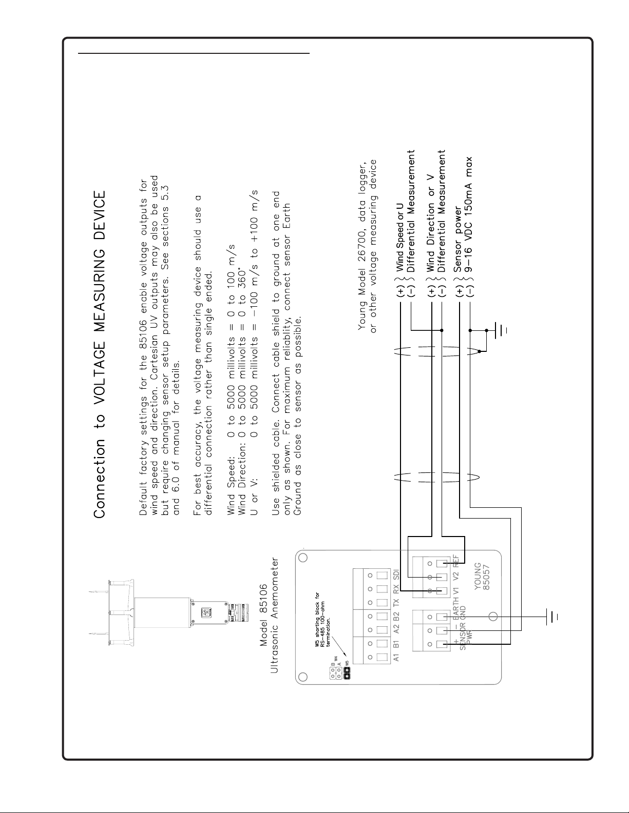
5.2 Voltage Outputs 2
5.3 Serial Output Formats and Protocols 2
5.4 Low Power Operation 4
6.0 SETTING SERIAL OUTPUTS AND OPERATING PARAMETERS
6.1 Setup using Young the 2DSETUP program 4
6.2 Setup using terminal Program 4
6.3 Command Overview 4
6.4 Command Details 5
7.0 EXAMPLE SETTINGS 6
7.1 Voltage Output, Minimum Power 6
7.2 RS232, Continuous ASCII, Minimum Power 6
7.3 RS232, Polled ASCII , Minimum Power 6
7.4 RS232, Polled ASCII Output 6
7.5 SDI-12 Continuous 6
7.6 SDI-12 Standby 6
8.0 WARRANTY 7
9.0 CE COMPLIANCE 7
APPENDIX
A WIRING CONNECTIONS 8
B SENSOR PHYSICAL 13
85106-90(F)
Page 3

Page 4
MODEL 85106
ULTRASONIC ANEMOMETER
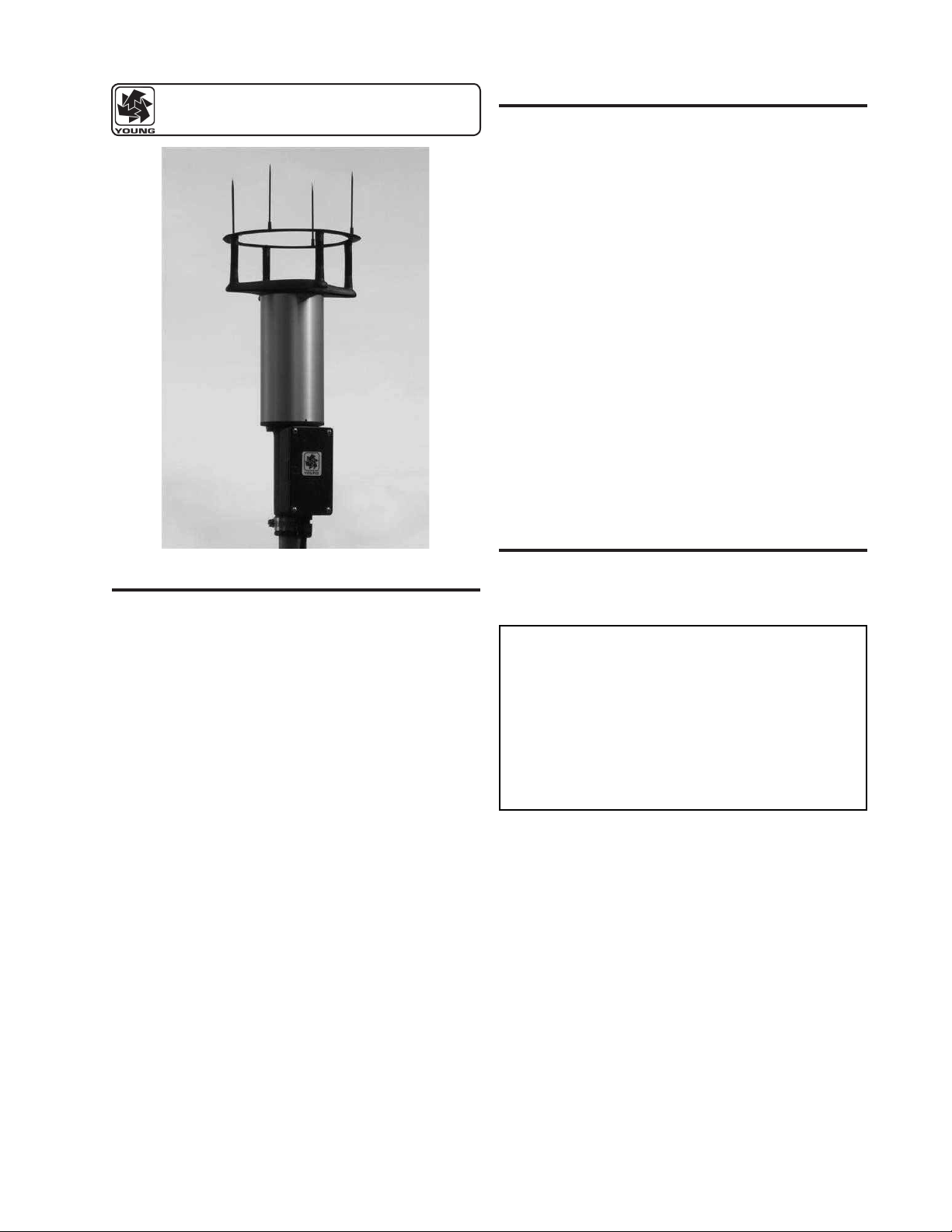
2.0 INTRODUCTION
The YOUNG Ultrasonic Anemometer is a 2-axis, no-moving-parts
wind sensor. It is ideal for general meteorological applications
requiring accurate and reliable measurement. The sensor features
wide operating range, compact size, e asy installation and low
power operation. Analog and digital signal outputs are available in
several popular formats.
The Ultrasonic Anemometer measures wind based on the transit
time of ultrasonic pulses between four transducers. Air ow alters
the transit time which is used to calculate flow velocity. Wind
direction is determined from relative velocities along each acoustic
path.
Me a s u r e m e n t results ar e av a i lable as cali b r a t e d voltage
output signals or serial data using RS-232, RS-485, or SDI-12
connections. Continuous output or polled operation may be used.
Serial formats may be selected for direct connection to YOUNG
Wind Tr acker d isp lay s, mari ne NMEA sy ste ms, SDI -12 d ata
loggers, and ASCII serial communication programs.
Operating parameter options are selected using a simple setup
program provided. All settings are stored internally in non-volatile
memory.
The sensor i s constructed usi ng UV-stabilized the rmoplastic,
stainless steel, and anodized aluminum for superior environmental
resistance. It is easily mounted on standard 1 inch (IPS) pipe.
An orientation ring preserves mounting position when the sensor
is removed.
3.0 INITIAL CHECKOUT
1.0 SPECIFICATIONS
WIND SPEED
Range: 0-70 m/s (156 mph)
Resolution: 0.1 m/s
Accuracy: 0 to 30 m/s, ±2% or 0.1m/s
30 to 70 m/s, ±3%
WIND DIRECTION
Azimuth Range: 0-360 degrees
Resolution: 1 degree
Accuracy: ± 2 degrees
SERIAL OUTPUT
Type: RS-232, RS-485, SDI-12
Formats: ASCII Text (polled and continuous)
RMYT (Wind Tracker)
NMEA
SDI-12 (v1.3)
Baud Rates: 1200, 4800, 9600, and 38400 baud
ANALOG VOLTAGE OUTPUT
Polar
Wind Speed: 0 to 5000 mV (0 to 100 m/s)
Wind Direction: 0 to 5000 mV (0 to 360° or 0 to 540°)
Cartesian (UV)
U and V: 0 to 5000 mV (-100 m/s to +100 m/s)
GENERAL
Output rate: 1 Hz typical (selectable)
Power Supply: 9 to 16 VDC,
150 mA max
Dimensions: 34 cm high x 17 cm wide
Weight: 0.7 kg (1.5 lb)
Shipping Weight: 1.6 kg (3.5 lb)
Carefully unpack the unit and inspect for physical damage. Any
damage should be reported to the shipper. The sensor arrives fully
calibrated and ready to use. As supplied, the sensor is congured
as follows:
FACTORY DEFAULT CONFIGURATION:
Serial Output:
- NMEA Format
- RS-232
- RS-485 Output Only
- 4800 baud
Analog Voltage Outputs:
- Channel V1: Wind Speed
0-5000 mV = 0-100 m/sec
- Channel V2: Wind Direction
0-5000mV = 0-360 Deg
These settings will permit direct serial connection to the Young
Model 06206 Marine Wind Tracker and connection of the voltage
outputs to a voltage measuring device or datalogger. For other
avai lable s eri al o r voltage output co nfigu rat ions re fer to th e
appropriate sections of the manual.
A simple operational check of the sensor may be performed as
follows: (Requires Model 06206 Marine Wind Tracker)
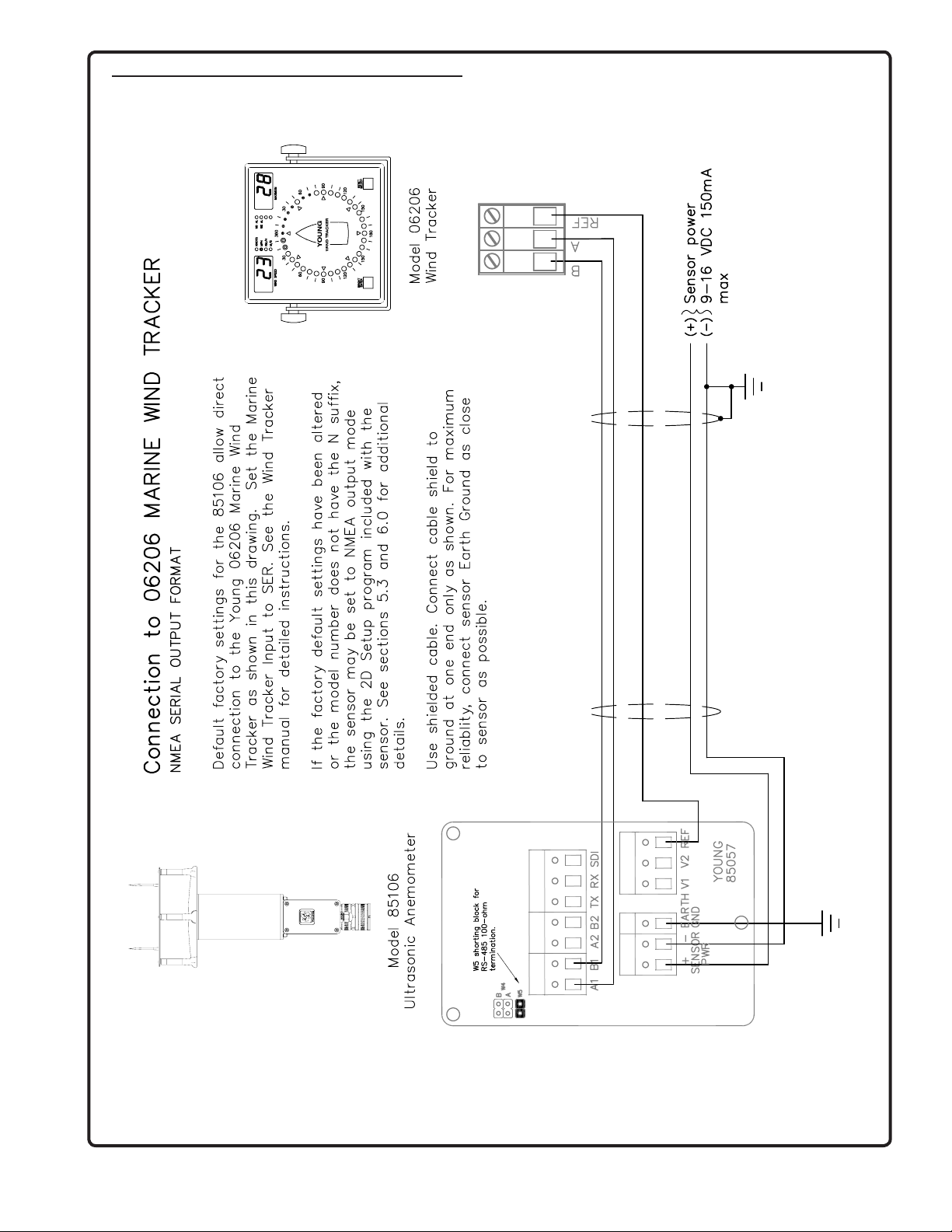
3.1 Remove j unction box cover and connect power and
si gnal wi res to te rmin als as in dica ted in WI R ING
CONNECTIONS (APPENDIX A). Supply voltage must
be 9 to 16 VDC.
IMPORTANT: The Wind Tracker input option must be
set to "SER". See the Wind Tracker manual for setting
this option.
3.2 Apply power to the Wind Tracker and sensor. There will
be a 5 second delay for initialization after which the unit
will begin to send data. Wind speed and wind direction
values will appear on the Wind Tracker.
Page 1
85106-90
Page 5

The sensor wind speed threshold is preset to 0.25 m/s
(0.6 mph). Wind below this level is displayed as zero.
The wind direction display will show the last value that
appeared when wind speed was above threshold.
3.3 Verify sensor response by using a small fan or gently
blowing through the measuring section. Move the fan to
create wind from several different directions and conrm
changes on the Wind Tracker display. Small fans and
gentle blowing create irregular ow patterns. This test is
for general checkout only.
If the Marine Wind Tracker display continuously shows "Ser Err"
then it is not receiving data from the sensor. Remove power and
check all wiring connections. If the problem cannot be corrected,
contact your YOUNG representative.
If the sensor is NOT USED with a YOUNG Marine Wind Tracker,
an alternative output must be used to check operation. For voltage
output, a voltmeter may be used as an indicator. For other serial
format s, use the wi ring d iagrams and appropr iate p aramete r
settings as a guide. See sections 5.0 and 6.0 of this manual.
IMPORTANT: NMEA, the default serial output format, transmits
AS C I I da t a . U si n g a co m m un i c at i o n pr o g ra m suc h as
HyperTerminal will allow for monitoring the serial output.
4.0 INSTALLATION
4.1 PLACEMENT
Proper instrument placement is important. Eddies from buildings,
trees, or other structu res c an in flu enc e mea sur eme nts . For
most applications , locate the sensor w ell above or upw in d of
obstructions. A s a ge neral rule, air flow around a structure is
disturbed to 2 times the height of the structure upwind, 6 times the
structure downwind, and up to 2 times the height of the structure
above ground.
4.2 MOUNTING AND ALIGNMENT
The sensor mounts to standard 1-inch (IPS) pipe with an outside
diameter of 1.34 inches (34 mm).
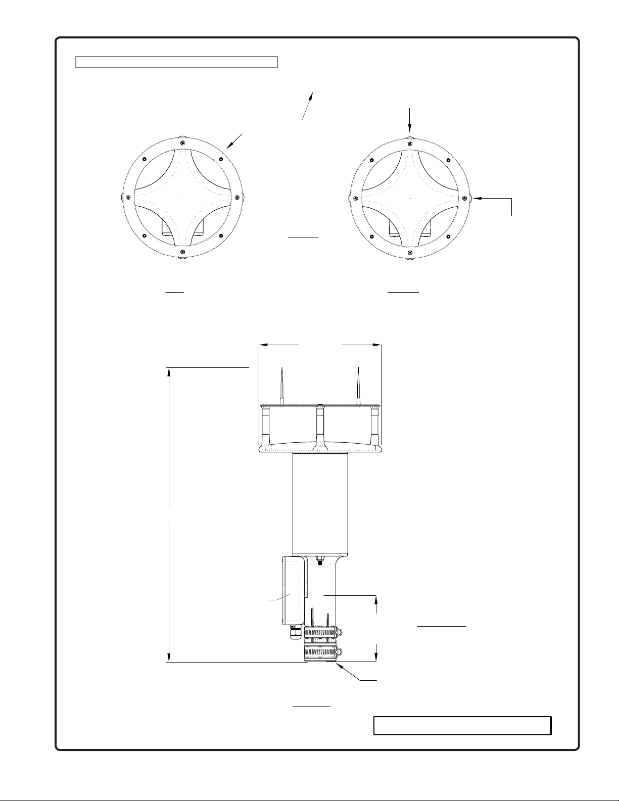
Generally, the sensor is aligned to north. In this orientation, the
sensor junction box faces south (180 degrees). The transducers
may be used as sighting aids. See diagram APPENDIX B.
4.2.1 Place orientation ring over pipe with guide pin up.
4.2.2 Place sensor mounting post over pipe.
4.2.3 Using the transducers as a sighting aid, align the sensor
with a feature on the horizon that represents the proper
orientation. After alignment, tighten the mounting post
band clamp to secure the position. DO NOT OVERTIGHTEN.
4.2.4 Slide t he orienta tion ring up so it s guide p in is ful ly
engaged in the sensor mounting post notch. Tighten the
orientation ring band clamp to secure its position. DO
NOT OVER- TIGHTEN.
If the sensor needs to be removed later, leave the orientation ring
on the pipe to preserve sensor alignment.
4.3 CONNECTIONS
With long ca ble lengths, resistance in the pow er supply wires
reduces the available voltage at the sensor. Power at the sensor
must be in the range of 9 to 16 VDC when the sensor is operating.
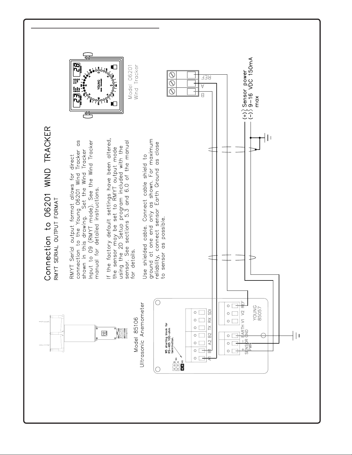
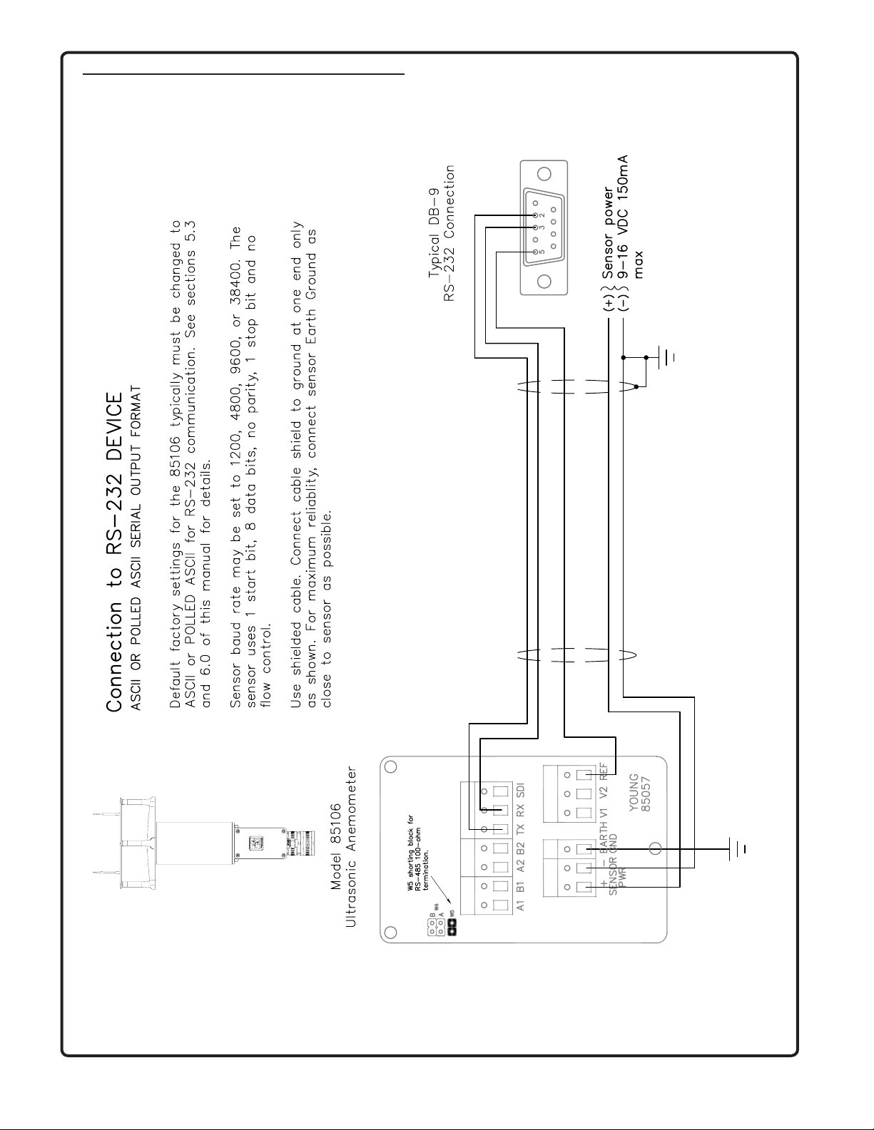
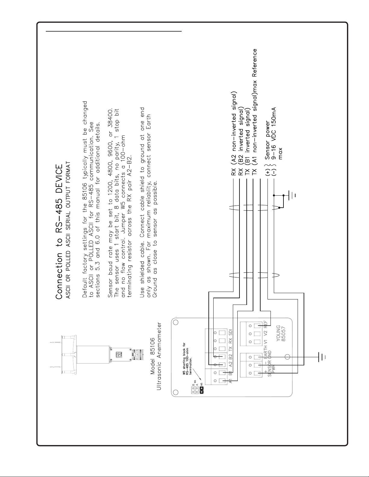
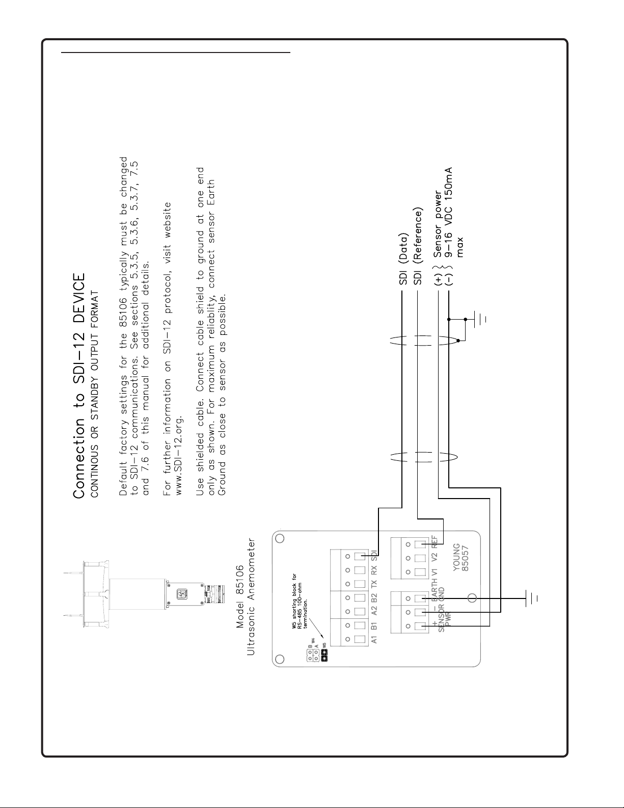
See WIRING DIAGRAMS in APPENDIX A.
5.0 OPERATION
5.1 WITH YOUNG MARINE WIND TRACKER DISPLAY
The default serial output format is NMEA which is compatible with
the Young Model 06206 Marine Wind Tracker display. The Marine
Wind Tracker receives measurements in the form of ASCII data
via an RS-485 serial connection. The Wind Tracker automatically
converts the data to wind values which appear on the display. Set
the Wind Tracker input to 'SER'. See the Marine Wind Tracker
manual for display options.
5.2 VOLTAGE OUTPUTS
When the default NMEA format is used, analog voltage outputs are
active. These may be connected to a data logger or other device
such as the YOUNG Model 26700 Programmable Translator. See
VOLTAGE OUTPUTS in APPENDIX A for connection details and
calibration values.
Voltage outputs may be enabled with any serial output format
except SDI-12 even if the serial output connection itself is disabled.
Polar speed and direction, which is the default, or Cartesian (UV)
voltage output format may be selected. See section 6.4.13 and
APPENDIX B for additional details. The voltage output may also be
set to signal the STATUS CODE. The default setting causes VOUT
to ignore the STATUS CODE. See sections 5.3.2 and 6.4.14 for
additional details.
When cable length between voltage output terminals and data
acquisition system exceeds 3m (10 ft.), the voltage outputs should
be measured differentially.
5.3 SERIAL OUTPUT FORMATS
A variety of serial output formats are available. From the factory, it
is programmed for operation with the Young Marine Wind Tracker
display (NMEA format). Other serial formats are selected using a
PC and the Windows 2DSETUP program (2Dsetup.exe) provided.
The following sections discuss format options availabl e. Each
command is discussed in detail in section 6.0.
5.3.1 RMYT
RMYT is a 6-byte binary data format sent at 9600 baud using the
RS -485 OUTPUT ONLY connections. This format is used with the
YOUNG Model 06201 Wind Tracker.
If RMYT default param eters are use d (n o ot her paramete rs
altered), the maximum number of internal samples are always
used, measurements and outputs run continuously, voltage outputs
are enabled , and bot h RS -23 2 an d RS-485 con necti ons are
enabled. The average current consumption is about 150 mA, not
including heater power.
5.3.2 ASCII
ASCII output provides continuous wind measurement data in text
format. Between each measurement cycle, the sensor goes into a
low power mode. There are a number of parameters related to the
ASCII serial output format which may be altered. Please note that
the default values are recommended for most applications.
Careful analysis of the sensor's application should be done prior
to making changes due to the interaction of parameters such as
OUTPUT DELAY and SAMPLE COUNT. See section 6.0.
ASCII outp ut a ppears eithe r in POL AR o r CA RT ESIAN (UV )
format. With POLAR format, the wind speed threshold and wind
speed units are selected. With CARTESIAN format, the threshold
is ignored and wind speed units are always meters per second
(m/s).
85106-90
Page 2
Page 6

ASCII POLAR FORMAT
a www.w ddd ss*cc<CR>
SDI-12 SENSOR
COMMAND RESPONSE
where
a = Sensor address
www.w = Wind speed (selected units)
ddd = Wind direction (degrees)
ss = Status code
* = Asterisk (ASCII 42)
cc = Checksum
<CR> = Carriage return (ASCII 13)
ASCII CARTESIAN (UV) FORMAT
a uu.uu vv.vv ss*cc<CR>
where
a = Sensor address
±uu.uu = U-axis wind speed (m/s)
±vv.vv = V-axis wind speed (m/s)
ss = Status code
* = Asterisk (ASCII 42)
cc = Checksum
<CR> = Carriage return (ASCII 13)
The CHECKSUM is the two-character printable hexadecimal value
generated by taking the exclusive-or of all characters up to the
asterisk. The STATUS CODE will show a non-zero value only when
the sensor cannot acquire sufficient samples or a measurement
error has occurred.
5.3.3 ASCII POLLED
ASCII POLLED format is the same as ASCII but sends data only
when polled. The sensor stays in low power mode until polled. The
polling command is Ma! where 'a ' is the sensor address. The
default address is '0' (ASCII 48).
5.3.4 NMEA
NMEA format provides continuous wind measurements in standard
NMEA marine sentences at 4800 baud using the RS-485 output
connections. Output is sent once per second. The output data may
be used with the YOUNG Model 06206 Marine Wind Tracker or
other NMEA-capable device.
NMEA FORMAT
$WIMWV,ddd,R,www.w,N,A*cc<CR><LF>
where
ddd = Wind direction (degrees)
www.w = Wind speed (knots)
* = Asterisk (ASCII 42)
cc = Checksum
<CR><LF> = Carriage return, line feed (ASCII 13, 10)
The CHECKSUM is the two-character printable hexadecimal value
generated by taking the exclusive-or of all characters between '$'
and '*'.
NMEA is the default setting so that the sensor may be connected
to a Marine Wind Tra cke r wit hou t alt eri ng an y oth er sensor
parameters.
5.3.5 SDI-12 CONT
SDI-12 CONT makes continuous wind measurements that may be
retrieved with SDI-12 R, M, and C commands. With R commands,
the sensor responds by sending measurement data. With M and
C commands, the sensor responds with an acknowl edgement
showing zero seconds measurement delay. No service request is
sent. Data may be retrieved immediately after an M or C command
with a D command.
If an R, M, or C command includes the CRC designator, retrieved
data will contain an SDI-12 CRC checksum.
aR0! a+www.w+ddd<CR><LF>
aR1! a±uu.uu±vv.vv<CR><LF>
aRC0! a+www.w+ddd<CRC><CR><LF>
aRC1! a±uu.uu±vv.vv<CRC><CR><LF>
aM! a0002<CR><LF>
aM1! a0002<CR><LF>
aMC! a0002<CR><LF>
aMC1! a0002<CR><LF>
aC! a00002<CR><LF>
aC1! a00002<CR><LF>
aCC! a00002<CR><LF>
aCC1! a00002<CR><LF>
aD0! a+www.w+ddd<CRC><CR><LF>
a±uu.uu±vv.vv<CRC><CR><LF>
where:
a = Sensor address
ddd = Wind direction (degrees)
www.w = Wind speed (selected units)
±uu.uu = U-axis wind speed (m/s)
±vv.vv = V-axis wind speed (m/s)
<CRC> = CRC checksum (only where requested)
<CR><LF> = Carriage return, line feed (ASCII 13, 10)
5.3.6 SDI-12 STANDBY
SD I - 1 2 STA N D B Y makes wind me a s u r e m e n t s on l y when
polled with an M or C command. The sensor responds with an
acknowledgement indicating that the data will be ready in one
second. With M commands, the sensor sends a service request as
soon as data are ready. Data are retrieved with D commands. If
the M or C command includes a CRC designator, retrieved data
will include a CRC checksum. After each measurement cycle, the
sensor goes into ultra-low power (320 uA) standby. Set Damping
Factor (see 6.4.9) to 0 when using SDI-12 STANDBY.
SDI-12 SENSOR
COMMAND RESPONSE
aM! a0012<CR><LF>
aM1! a0012<CR><LF>
aMC! a0012<CR><LF>
aMC1! a0012<CR><LF>
aC! a00102<CR><LF>
aC1! a00102<CR><LF>
aCC! a00102<CR><LF>
aCC1! a00102<CR><LF>
aD0! a+www.w+ddd<CRC><CR><LF>
a±uu.uu±vv.vv<CRC><CR><LF>
where:
a = Sensor address
ddd = Wind direction (degrees)
www.w = Wind speed (selected units)
±uu.uu = U-axis wind speed (m/s)
±vv.vv = V-axis wind speed (m/s)
<CRC> = CRC checksum (only where requested)
<CR><LF> = Carriage return, line feed (ASCII 13, 10)
5.3.7 ADDITIONAL SDI-12 INFORMATION
The 85004 sensor conforms to all aspects of the SDI-12 version
1.3 protocol and will respond to the additional commands listed
below. For further information on the SDI-12 protocol, visit www.
sdi-12.org on the web.
SDI-12 SENSOR
COMMAND RESPONSE
?! a<CR><LF>
a! a<CR><LF>
Page 3
85106-90
Page 7

aI! a13 YOUNG 85000 v1.00<CR><LF>
aAb! b<CR><LF>
a = Sensor address
b = New sensor address
aV! a0004<CR><LF>
Retrieve V data with D command.
Response listed next.
aD0! a+sc+fmt+thresh+damp<CR><LF>
a = Sensor address
sc = sample count 0-99
fmt = SDI-12 format 0=CONT, 1=STANDBY
thresh = Polar threshold (cm/s)
damp = Damping factor
aX1nn! None. nn = Sample count 00 or 03-31
aX2n! None. n =SDI-12 format 0 = CONT
1 = STANDBY
aX3nnn! None. nnn = Polar threshold 0-999 cm/s
aX4nn! None. nn = Damping factor 0-99
5.4 LOW POWER OPERATION
Average current consumption with default settings is about 150
mA. This conguration uses no power conservation and enables
all features even though they may not be used. Average current
consumption with once-per-second ASCII serial output and typical
power conservation settings is about 30 mA. This is suitable for
many low power applications.
To reduce current consumption further, additional strategies must
be employed. These include disabl ing unused ou tputs, using
polled serial operation, increasing the delay between samples, and
limiting the sample count to the minimum optimal number. Faster
baud rates reduce power by limiting transmit duration.
Lowest power consumption is realized with SDI-12 output format.
However, this requires use with an SDI-12 compatible data logger.
Wit h SDI-12, the average current consum pt io n may easily be
reduced to less than 12 mA during measurements and 320 uA in
standby.
If the prompt does not appear after receiving three ESC characters,
re-check the wiring and communication program setup. If the
sensor baud rate is unknown, try sending the ESC characters
at each of the four available baud rates (1200, 4800, 9600, and
38400) . It is a lso possibl e that par ameters hav e been set to
purposefully disable RS-232 or RS-485 connections. If this the
case, the following method must be used.
In order to provide access under all conditions, the sensor always
begins operation at power up with serial communications set to
38400 baud and RS-232 connections enabled. Immediately after
power up, there is a four second time window in which to send the
ESC characters and enter COMMAND MODE.
To use this feature, set a serial communication program (such
as HyperTermin al) to 38400 baud with no handshak ing. Apply
power to the sensor (the sensor must be off for about 30 seconds
before power up). The sensor will transmit "***" (three asterisk
characters) immediately after power up. Now send the three ESC
characters. The COMMAND MODE '>' prompt should appear.
6.3 COMMAND OVERVIEW
At the prompt, type '?? ' to display a list of available commands
and their format. Type 'RPT' to report current settings. (Note that
some values in the list cannot be set by the user.) Commands are
case sensitive and the exact format must be used. For example,
the SET 02 nn command requires two digits for the serial format
code. If you send S ET0 23 instead of SE T02 03, the sensor will
reject the command and indicate an error. Terminate all commands
with a carriage return (ASCII 13). In HyperTerminal, do this by
pressing the ENTER key.
When RMYT, NMEA, or SDI-12 serial format is selected, some
parameters are automatically changed. This may change the baud
rate from its current setting. See section 6.4.2 for details on which
parameters are altered.
Although new parameter values are stored immediately when the
command is issued, they do not take effect until the sensor enters
OPERATE MODE.
COMMAND DESCRIPTION
6.0 SETTING OUTPUTS AND OPERATING
PARAMETERS
6.1 SETUP WITH YOUNG 2DSETUP PROGRAM
(RECOMMENDED)
The 2DSETUP program supplied with the sensor provides an easy
method for checking and changing operating settings in the model
85000. Simply install the program on a Windows PC. Follow the
instructions to get the current settings from the sensor, change
settings, and send the new settings to the sensor.
6.2 SETUP USING ANOTHER COMMUNICATIONS PROGRAM
If desired, a serial communications program like HyperTerminal
may be used. Parameters are set using simple commands. A
limited numbe r of par amete rs m ay a lso be s et u sing SDI- 12
commands.
For serial communication, the sensor and communication program
must be at the same baud rate and the sensor must be properly
connected. The default baud rate is 9600 but may be set to 1200,
4800, or 38400. Either RS-232 or RS-485 full duplex may be used.
Set hardware handshaking to 'NONE' in your communications
program and use 1 start, 8 data, 1 stop bit.
Except for SDI- 12 forma t, the sensor m ust be in COM MAND
MODE in order to set parameters. COMMAND MODE is activated
by sending three ESC characters (ASCII 27) in quick succession
while the sensor is running. To signify that the sensor is ready to
accept commands, a '>' prompt character will appear.
85106-90
SET01nn Set OUTPUT MODE
01 Enable voltage output
02 Enable RS-232
04 Enable RS-485 full duplex
08 Enable RS-485 half duplex
16 Enable RS-485 output only
SET02nn Set OUTPUT FORMAT
01 RMYT (default)
02 ASCII
03 ASCII POLLED
04 NMEA
05 SDI-12 CONTINUOUS
06 SDI-12 STANDBY
SET03nn Set BAUD RATE
12 1200
48 4800
96 9600
38 38400
SET04nn Set ASCII WS UNITS
01 MPH
02 KNOTS
03 KMPH
04 M/S
SET05c ASCII character sensor address (0-9, A-Z, a-z)
SET06nnn Wind speed threshold for polar output (cm/s)
SET07nnnnn Wind speed scale (nnnnn/10000)
SET08nnnnn Direction offset (±nnnnn degrees x 10)
SET09nn Damping factor
SET10nnn Output delay (0-999 x 8.192 milliseconds)
SET11nn Direction VOUT (36=0-360, 54=0-540 degrees)
SET12nn Sample count (00=auto or 03-31)
Page 4
Page 8

SET13nn ASCII and Vout format (00=polar, 01=UV)
SET14nn Vout Status Code (1=none, 2=0V, 3=FS)
CALnn Force Vout (00=0V, 01=5V)
XX Go to OPERATE MODE
RPT Report parameter settings
?? Help list
6.4 COMMAND DETAILS
6.4.1 SET01nn SET OUTPUT MODE
This par ame ter independ ently e nable s and disab les vol tage
output, RS-232, and RS-485 connections. For example, to enable
voltage output, RS-232, and RS-485 full duplex, add the code for
each one: 01 + 02 + 04 = 07, S ET0107. To enable only RS-232:
SET0102. If RS-485 is used, choose only one RS-485 option (04,
08, or 16). See section 6.3 for codes.
To reduce power consumption, enable only those outputs that
are needed. When SDI-12 format is selected with the SET 02 nn
command, voltage output, RS-232, and RS-485 connections are
disabled and SDI-12 is enabled.
6.4.2 SET02nn SET OUTPUT FORMAT
This parameter determines the serial ou tput data format. See
section 5.0 for operational details. When selecting some formats,
parameters are automatically changed as listed below:
FORMAT ADDITIONAL
CODE PARAMETERS CHANGED
01 RMYT BAUD = 9600
OUTPUT MODE = 07
THRESHOLD = 25 cm/s
OUTPUT DELAY = 01
SAMPLE COUNT = 31
02 ASCII
03 ASCII POLLED None
04 NMEA BAUD = 4800
OUTPUT MODE = 19
THRESHOLD = 25 cm/s
OUTPUT DELAY = 122
SAMPLE COUNT = 31
05 SDI-12 CONT
06 SDI-12 STANDBY 1200 baud
Both SDI-12 settings automatically disable voltage output, RS-232,
and RS-485 connections. With either POLLED ASCII or SDI-12
STANDBY, set the Damping Factor to 0 (see section 6.4.9).
6.4.3 SET03nn SET BAUD RATE
All RS-232 and RS-485 communication use the baud rate set with
this parameter. Power consumption is affected by this setting since
it inuences communication duration.
6.4.4 SET04nn SET ASCII WIND SPEED UNITS
Sets wind speed units for ASCII, ASCII POLLED, and SDI-12 polar
outputs only.
6.4.5 SET05c SET POLL ADDRESS CHARACTER
Sets the sensor address for ASCII POLLED and SDI-12 formats.
The default is '0' (ASCII 48).
6.4.6 SET06nn SET WIND SPEED THRESHOLD
Sets the wind speed threshold for polar outputs (wind speed and
direction) to suppress scattered wind direction indications in calm
air. Winds below the threshold are reported as zero, wind direction
is held at last value when wind speed was above threshold. Set
threshold in centime te rs per second (m/s x 100). Th e default
setting is 25 cm/s (0.25 m/s, 0.56 mph).
6.4.7 SET07nnnnn SET WIND SPEED MULTIPLIER
All wind speed measurements are multiplied by this parameter.
The default value is 10000 for a multiplier of 1.0000. This may be
used to individually calibrate each sensor for improved accuracy.
6.4.8 SET08nnnnn SET WIND DIRECTION OFFSET
Use this parameter to add or subtract a wind direction offset. Value
is degrees x 10 and may be positive or negative. Wind direction
is always re-scaled to a 0-360 range after offset is applied. The
default value is 00000.
6.4.9 SET09nn SET DAMPING FACTOR
Wind m easureme nt ou tputs a re damped us ing the f ollowing
formula:
S
damped
= [(d-1) * S
damped
+ S
sample
] / d
where:
S
S
damped
sample
= New or last damped wind speed
= New wind speed speed
d = Damping factor
The default value is 4. When set to 00, no damping is applied.
Higher damping factors slow the rate at which the sensor indicates
wind changes.
6.4.10 SET10nnn SET OUTPUT DELAY
Sets the amount of time between measurements in increments of
8.192 milliseconds. The default value is 122 ( 0.9994 seconds).
Lower values (less delay) increase power consumption when
continuous measurements are taken.
6.4.11 SET11nn SET DIRECTION VOUT
Sets wind d ire cti on voltage outp ut sc ale t o 0 -36 0 or 0- 540
degrees. Use the 0-540 scale if possible. When set to 0-360, wind
directions fluctuating about north cause voltage output swings
between zero and full scale. Data loggers or display systems may
sample during these transitions causing erroneous readings. A
0-540 scale eliminates output transitions with northerly wind.
Data in 0-540 form may be re-scaled to 0-360 by subtracting 360
degrees from any value greater than or equal to 360. The default
parameter setting is 0-360 for systems that cannot re-scale the
0-540 output.
6.4.12 SET12nn SET SAMPLE COUNT
All mea surements are ca lculate d from the medi an of 3 to 3 1
sample sets. More samples consume more power. More samples
are required at higher wind speeds or in conditions where adequate
samples are difcult to acquire. If SAMPLE COUNT is set to 00,
the sensor automatically uses the minimum number of sample sets
needed to produce valid data. However, when powered up for the
rst time or when polling at intervals longer than a few seconds,
the sensor may requir e more than one m easurement cycle to
determine the optimum number of sample sets.
In applications where power consumption is not an issue or where
the sensor must acquire results on the rst measurement cycle, the
SAMPLE COUNT may be set manually to the highest anticipated
wind speed (m/s) up to 31 which is the maximum SAMPLE COUNT
value. Wind speeds above 31 m/s will use 31 sample sets.
6.4.13 SET13nn SET ASCII and Vout FORMAT
Serial ASCII and ASCII POLLED formats may be set to provide
wind data in either Polar (speed and direction) or Cartesian (UV)
form. This setting also determines the whether voltage outputs are
in Polar or Cartesian format.
00= Polar, 01=Cartesian (UV).
6.4.14 SET14n SET VOLTAGE OUTPUT STATUS
Page 5
85106-90
Page 9

Se rial ASC I I a nd A SCII PO LLED fo r mat s r e port a STATUS
CODE where non-zero values indicate insufficient samples or
measurement error. SET14n determines how the STATUS CODE
is handled in the voltage output.
1 = None (ignore STATUS CODE)
2 = Set Vouts to 0V when STATUS is non-zero
3 = Set Vouts to 5V full scale when STATUS is non-zero
6.4.15 CALnn FORCE VOUT
This command forces both voltage outputs channel to either 0mV
or 5000 mV. This may be used to calibrate or check the operation
of external data acquisition devices. 00=0 mV, 01=5000 mV
6.4.16 XX, RPT, and ??
XX Returns the sensor to OPERATE MODE.
RPT Reports the latest parameter settings.
?? Prints a list of commands.
7.0 EXAMPLE SETTINGS
Use the 2DSETUP program for the following suggested settings.
Not all possible setting combinations are shown.
7.6 SDI-12 STANDBY
Serial Output Format: SDI-12 STANDBY
Output Delay: 0
Damping Factor: 0
Sample Count: Set to 0 if polling frequently. Set to
highest anticipated wind speed (m/s)
up to 31 if polling infrequently. Average
current consumption is a function of
polling rate and sample count.
8.0 WARRANTY
This product is warranted to be free of defects in materials and
construction for a period of 12 months from date of initial purchase.
Liability is limited to repair or replacement of defective item. A
copy of the warranty policy may be obtained from R. M. Young
Company.
9.0 CE COMPLIANCE
This product has been tested and shown to comply with European
CE requirements for the EMC Directive. Please note that shielded
cable must be used.
7.1 VOLTAGE OUTPUT ONLY, MINIMUM POWER
Serial Output Format: ASCII
RS-232 Disabled
RS-485 Disabled
Voltage Output: Enabled
Output Delay: 122
Sample Count: 0
7.2 RS-232 ONLY, CONT ASCII OUTPUT, MINIMUM POWER
Serial Output Format: ASCII
RS-232 Enabled
RS-485 Disabled
Voltage Output: Disabled
Output Delay: 122
Sample Count: 0
7.3 RS-232 ONLY, POLLED ASCII OUTPUT, MINIMUM POWER
Serial Output Format: ASCII POLLED
RS-232 Enabled
RS-485 Disabled
Voltage Output: Disabled
Sample Count: 0
7.4 RS-232 ONLY, POLLED ASCII OUTPUT
Serial Output Format: ASCII POLLED
RS-232 Enabled
RS-485 Disabled
Voltage Output: Disabled
Sample Count: Set to 0 if polling frequently. Set to
highest anticipated wind speed (m/s)
up to 31 if polling infrequently. Average
current consumption is a function of
polling rate and sample count.
Declaration of Conformity
R. M. Young Company
2801 Aero Park Drive
Traverse City, MI 49686 USA
Model 85106
The undersigned hereby declares on behalf of R. M.
Young Company that the above-referenced product, to
which this declaration relates, is in conformity with the
provisions of:
Council Directive 2004/108/EC (December 15, 2004)
on Electromagnetic Compatibility
David Poinsett
R&D Manager
7.5 SDI-12 CONTINUOUS
Serial Output Format: SDI-12 CONT
Output Delay: 0
Sample Count: 0
85106-90
Page 6
Page 10
APPENDIX A: WIRING CONNECTIONS
Page 7
85106-90
Page 11
APPENDIX A: WIRING CONNECTIONS
85106-90
Page 8
Page 12
APPENDIX A: WIRING CONNECTIONS
Page 9
85106-90
Page 13
APPENDIX A: WIRING CONNECTIONS
85106-90
Page 10
Page 14
APPENDIX A: WIRING CONNECTIONS
Page 11
85106-90
Page 15
APPENDIX A: WIRING CONNECTIONS
85106-90
Page 12
Page 16
MODEL 85106 ULTRASONIC ANEMOMETER
+V
(WIND FROM NORTH)
+U
(WIND FROM EAST)
(U-V)
CARTESIAN
POLAR
(SPEED, WIND DIRECTION)
EXAMPLE:
WIND AT 45°
E - 90°
N - 0°
W - 270°
S - 180°
FRONT VIEW
MOUNTING:
STANDARD 1" NPT PIPE
1.32" DIA (Ø34.0MM)
ORIENTATION RING
WHEN PROPERLY
ALIGNED, JUNCTION
BOX FACES SOUTH
NORTH
TOP VIEW
407 [16.0]
INSTALL VERTICALLY AS SHOWN TO AVOID
MOISTURE DAMAGE TO CIRCUITRY.
MOUNTING
DEPTH
114 [4.5]
170 [6.7]
APPENDIX A: WIRING CONNECTIONS
Page 13
85106-90
 Loading...