

York YP8C080C16MP11, YPLC, YP8C100C16MP11, YP8C100C20MP11, YP8C120C20MP11 Technical Manual
...Page 1
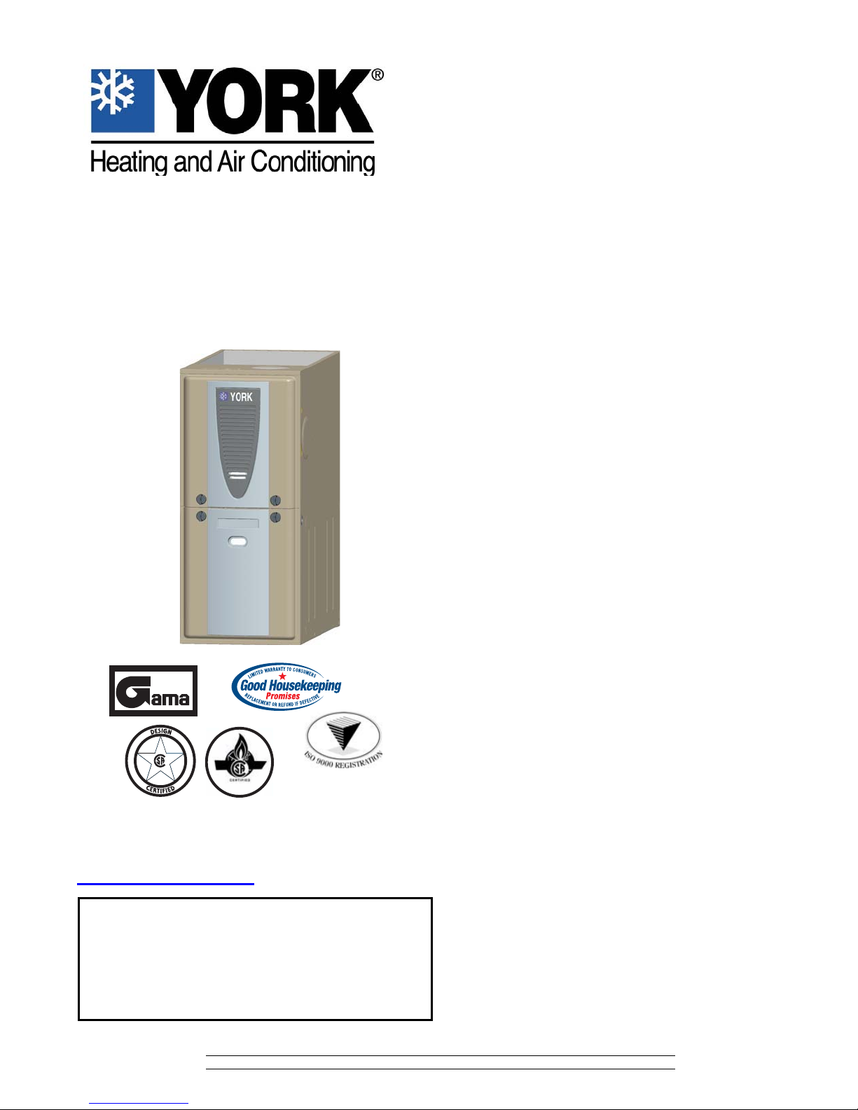
TECHNICAL GUIDE
80% MODULATING (ECM MOTOR)
GAS-FIRED RESIDENTIAL
MULTI-POSITION GAS FURNACES
STANDARD & Low NOx MODELS
MODELS: YP8C / YPLC
NATURAL GAS
60 - 120 MBH INPUT
Due to continuous product improvement, specifications are
subject to change without notice.
Visit us on the web at www.york.com
Additional rating information can be found at
www.ahridirectory.org
WARRANTY
Lifetime limited warranty on heat exchanger to the original purchaser; a
20-year limited warranty from original installation date to subsequent
purchaser.
10-year warranty on the heat exchanger in commercial applications.
Standard 5-year limited parts warranty.
Extended 10-year limited parts warranty when product is registered online within 90 days of purchase for replacement or closing
for new home construction.
EFFICIENCY
RATING
CERTIFIED
ISO 9001
Certified Quality
Management System
402703-YTG-C-0409
DESCRIPTION
These compact units employ induced combustion, reliable hot
surface ignition and high heat transfer aluminized tubular heat
exchangers. The units are factory shipped for installation in
upflow or horizontal applications and may be converted for
downflow applications.
These furnaces are designed for residential installation in a
basement, closet, alcove, attic, recreation room or garage and
are also ideal for commercial applications. All units are factory
assembled, wired and tested to assure safe dependable and
economical installation and operation.
These units are Category I listed and may be common vented
with another gas appliance as allowed by the National Fuel Gas
Code.
FEATURES
• Modulating heating operation includes:
- Modulating gas valve, inducer and circulating blower
- Modulating operation from 100% input to 50% input in 1%
increments
• Easily applied in upflow, horizontal left or right, or downflow
installation with minimal conversion necessary.
• Compact, easy to install, ideal height 33" tall cabinet.
• ECM variable speed motor for cooling SEER enhancement,
blower delay options for comfort, and continuous fan options
for IAQ performance.
• Easy access to controls to connect power/control wiring.
• Built-in, high level self diagnostics with fault code display.
• Low unit amp requirement for easy replacement application.
• All models are convertable to use propane (LP) gas.
• Electronic Hot Surface Ignition saves fuel cost with
increased dependability and reliability.
• 100% shut off main gas valve for extra safety.
• 24V, 40 VA control transformer and blower relay supplied for
add-on cooling.
• Hi-tech tubular aluminized steel primary heat exchanger.
• Blower door safety switch.
• Solid removable bottom panel allows easy conversion.
• Low NOx models have been designed to meet specific code
requirements.
• Airflow leakage less than 1% of nominal airflow for
ductblaster conditions.
• No knockouts to deal with, making installation easier.
• Movable duct connector flanges for application flexibility.
• Quiet inducer, burner and blower operation.
• Inducer rotates for easy conversion of venting options.
• Fully supported blower assembly for easy access and
removal of blower.
• External air filters used for maximum flexibility in meeting
customers IAQ needs.
• Venting applications - may be installed as a common vent
with other gas-fired appliances.
• Insulated blower compartment for thermal and acoustic
performance.
• 1/4 turn knobs provided for easy door removal.
FOR DISTRIBUTION USE ONLY - NOT TO BE USED AT POINT OF RETAIL SALE
Page 2
402703-YTG-C-0409
LEFT SIDE
RIGHT SIDE
.5”
.5”
RETURN END
B
24.25”
30.25”
28.5”
Gas Pipe
Entry
Thermostat
Wiring
FRONT
14”
1”
1.5”
23”
SUPPLY END
C
24.38”
20”
.5”
B
Gas Pipe
Entry
Thermostat
Wiring
33”
A
.5”
Electrical
Entry
Electrical
Entry
Vent Connection
Outlet
Vent
Connection
Outlet
4” Diameter
Outlet
Vent Connection
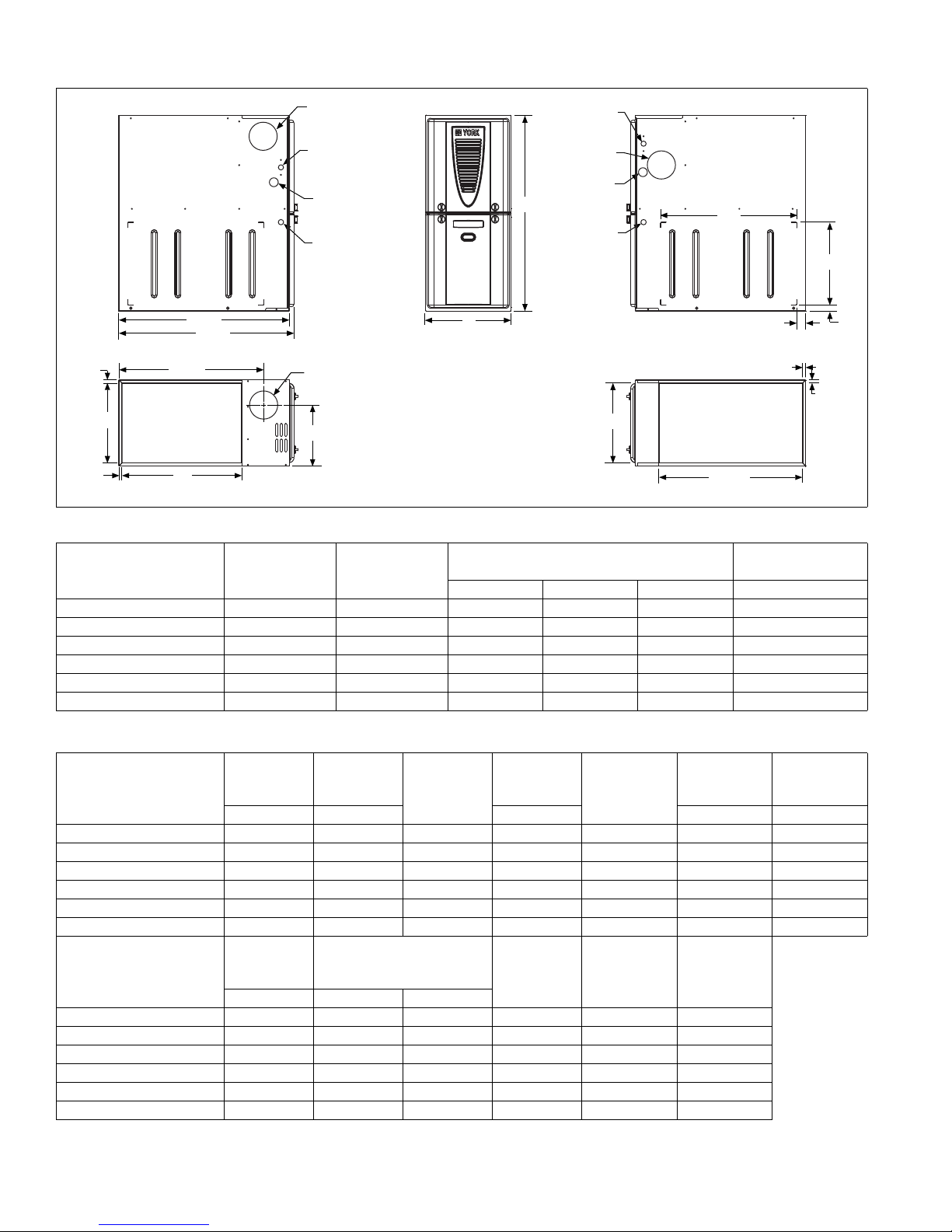
Cabinet and Duct Dimensions
Approximate
Operating Weights
Models
Nominal
CFM (m
3
/min)
Cabinet
Size
Cabinet Dimensions (Inches)
A B C Lbs
YP(8,L)C060A12MP11 1200 A 14 1/2 13 1/4 10.3 94
YP(8,L)C080B12MP11 1200 B 17 1/2 16 1/4 11.8 103
YP(8,L)C080C16MP11 1600 C 21 19 3/4 13.6 114
YP(8,L)C100C16MP11 1600 C 21 19 3/4 13.6 118
YP(8,L)C100C20MP11 2000 C 21 19 3/4 13.6 122
YP(8,L)C120C20MP11 2000 C 21 19 3/4 15.8 129
Ratings & Physical / Electrical Data
Input
Models
Max/Min
MBH MBH CFM °F °F
YP(8,L)C060A12MP11 60/30 47/24 80.0 1200 7.0 30-60 20-50
YP(8,L)C080B12MP11 80/40 62/32 80.0 1200 7.5 40-70 20-50
YP(8,L)C080C16MP11 80/40 62/32 80.0 1600 10.0 35-65 20-50
YP(8,L)C100C16MP11 100/50 78/40 80.0 1600 10.0 35-65 20-50
YP(8,L)C100C20MP11 100/50 78/40 80.0 2000 12.0 35-65 20-50
YP(8,L)C120C20MP11 120/60 95/48 80.0 2000 12.0 45-75 25-55
Models
Max.
Outlet
Air Temp
°F HP Amps
Output
Max/Min
Blower
AFUE
Nominal
Airflow
Blower
Wheel
size
Total
Unit
Amps
Max
Over-Current
Protect
Air Temp.
Rise Max
Input
Min. wire Size
(awg) @ 75 ft
one way
YP(8,L)C060A12MP11 160 1/2 4.8 11 x 8 15 14
YP(8,L)C080B12MP11 170 1/2 4.8 11 x 8 15 14
YP(8,L)C080C16MP11 165 3/4 7.5 11 x 10 15 14
YP(8,L)C100C16MP11 165 3/4 7.5 11 x 10 15 14
YP(8,L)C100C20MP11 165 1 14.5 11 x 11 20 12
YP(8,L)C120C20MP11 175 1 14.5 11 x 11 20 12
Annual Fuel Utilization Efficiency (AFUE) numbers are determined in accordance with DOE Test procedures.
Wire size and over current protection must comply with the National Electrical Code (NFPA-70-latest edition) and all local codes.
2 Johnson Controls Unitary Products
Air Temp.
Rise Min
Input
Page 3
402703-YTG-C-0409
FILTER PERFORMANCE
The airflow capacity data published in the “Blower Performance” table represents blower performance WITHOUT filters.
All applications of these furnaces require the use of field
installed air filters. All filter media and mounting hardware or
provisions must be field installed external to the furnace cabinet. DO NOT attempt to install any filters inside the furnace.
NOTE: Single side return above 1800 CFM is approved as long
as the filter velocity does not exceed filter manufacturer ’s recommendation and a transition is used to allow use of a 20 x 25
filter.
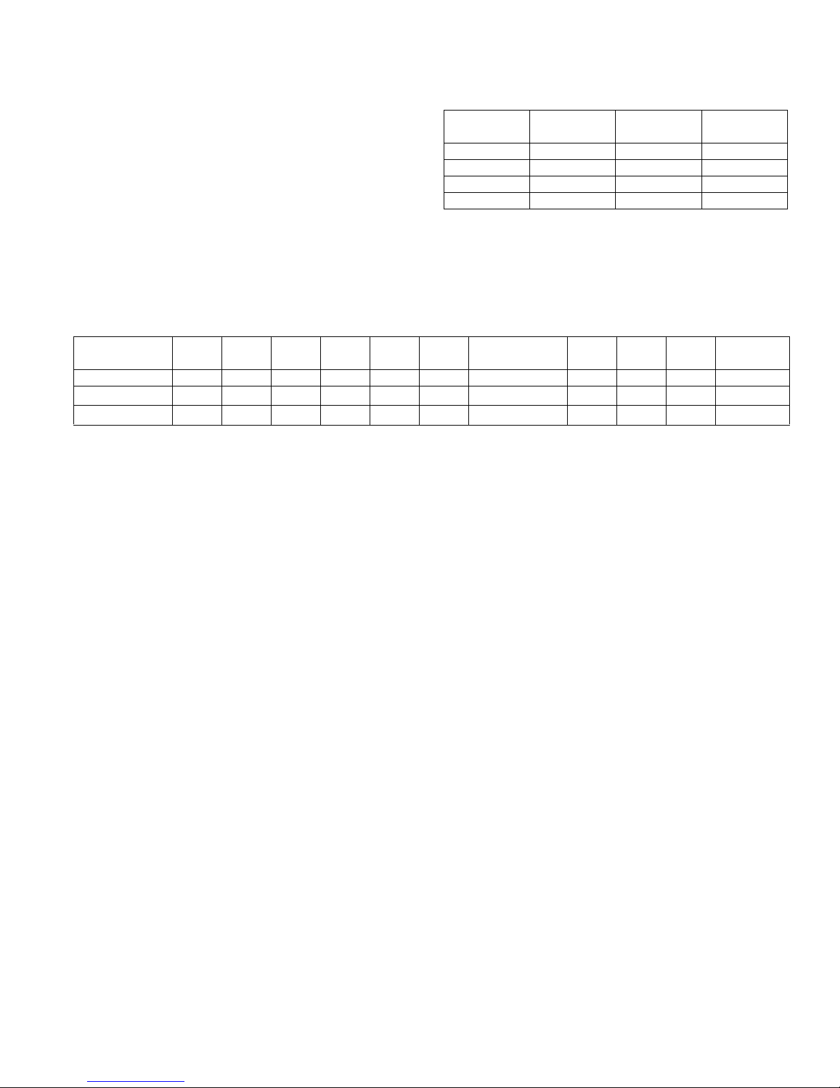
Recommended Filter Sizes
CFM
1200 A 16 x 25 14 x 25
1200 B 16 x 25 16 x 25
1600 C 16 x 25 20 x 25
2000 C (2) 16 x 25 20 x 25
NOTES:
1.Air velocity through throwaway type filters may not exceed 300 feet per minute (91.4 m/min). All velocities over this require the use of high velocity filters.
2.Do not exceed 1800 CFM using a single side return and a 16x25 filter. For
CFM greater than 1800, you may use two side returns or one side and the
bottom or one return with a transition to allow use of a 20x25 filter.
Cabinet
Size
Side
(in)
Bottom
(in)
Unit Clearances to Combustibles
Application Top Front Rear
Upflow B-Vent 130001CombustibleYesYesYes No
Downflow B-Vent130001
Horizontal B-Vent130001CombustibleNoYesYes
1. Special floor base or air conditioning co il required for use on combustible floor.
2. Line contact only permitted between lines formed by the intersection of the rear panel and side panel (top in horizontal position) of the furnace jacket and building
joists, studs or framing.
Left
Side
ACCESSORIES
PROPANE (LP) CONVERSION KIT -
1NP0680 - All Models
This accessory conversion kit may be used to convert natural
gas (N) units for propane (LP) operation.
SIDE RETURN FILTER RACKS -
1SR0200 - All Models
1SR0302 - All Models
1SF0101 - All Models
BOTTOM RETURN FILTER RACKS -
1BR0514 or 1BR0614 - For 14-1/2” cabinets
1BR0517 or 1BR0617 - For 17-1/2” cabinets
1BR0521 or 1BR0621 - For 21” cabinets
1BR05xx series are galvanized steel filter racks. 1BR06xx are
pre-painted steel filter racks to match the appearance of the furnace cabinet.
COMBUSTIBLE FLOOR BASE KIT -
For installation of these furnaces in downflow applications
directly onto combustible flooring material, These kits are
Right
Side
Flue
Floor/
Bottom
1
1
Closet Alcove Attic
Yes Yes Yes No
Line
Contact
Yes
EAC TRANSITION KITS -
For installation of EAC accessories with these furnaces to provide easy transition of return airflow through the EAC to get the
proper sealing and reduced airflow leakage.
1TK1001 - For all models using side return
1TK1014 - For 14-1/2” cabinets using bottom return
1TK1017 - For 17-1/2” cabinets using bottom return
1TK1021 - For 21” cabinets using bottom return
1TK1024 - For 24-1/2” cabinets using bottom return
HIGH ALTITUDE - No high altitude kits are required.
ROOM THERMOSTATS - A wide selection of compatible ther-
mosets are available to provide optimum performance and features for any installation.
1H/1C, manual change-over electronic non-programmable thermostat.
1H/1C, auto/manual changeover, electronic programmable,
deluxe 7-day, thermostat.
1H/1C, auto/manual changeover, electronic programmable.
* For the most current accessory information, refer to the price
book or consult factory.
2
required to prevent potential overheating situations. The se kits
are also required in any applications where the furnace in
installed in a downflow configuration without an evaporator coil,
where the combustible floor base kit provides access for combustible airflow.
1CB0514 - For 14-1/2” cabinets
1CB0517 - For 17-1/2” cabinets
1CB0521 - For 21” cabinets
Johnson Controls Unitary Products 3
Page 4
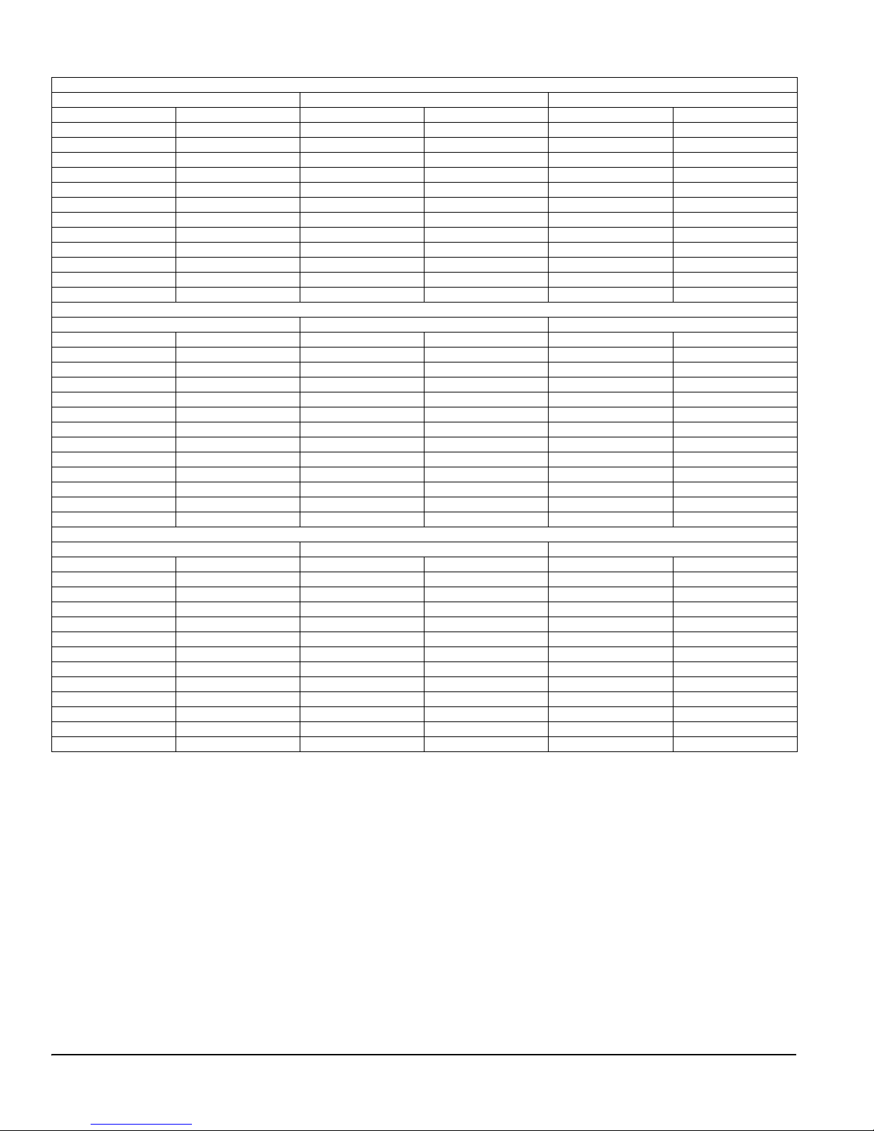
Blower Performance CFM - Any Position
High / Low Speed Cooling CFM
060A12 080B12 Jumper Settings
Hi Cool Lo Cool Hi Cool Lo Cool COOL Jumper ADJ Jumper
1340 900 1290 790 H B
1125 750 1065 660 MH B
1225 820 1165 720 H A
1050 680 960 600 MH A
1100 740 1050 590 H C
890 600 855 525 ML B
920 615 875 540 MH C
675 450 640 395 L B
815 545 775 495 ML A
600 440 580 380 L A
720 499 700 430 ML C
540 440 525 380 L C
High / Low Speed Cooling CFM
080C16 100C16 Jumper Settings
Hi Cool Lo Cool Hi Cool Lo Cool COOL Jumper ADJ Jumper
1715 1165 1600 1120 H B
1520 1020 1450 980 MH B
1575 1060 1500 1020 H A
1395 930 1345 900 MH A
1430 950 1315 930 H C
1320 875 1265 845 ML B
1260 840 1210 805 MH C
1100 730 1080 700 L B
1200 795 1165 765 ML A
1000 665 980 635 L A
1080 715 1050 695 ML C
900 600 885 585 L C
High / Low Speed Cooling CFM
100C20 120C20 Jumper Settings
Hi Cool Lo Cool Hi Cool Lo Cool COOL Jumper ADJ Jumper
2110 1360 1990 1290 H B
1670 1085 1760 1030 MH B
1900 1235 1900 1210 H A
1515 990 1510 935 MH A
1710 1130 1800 1095 H C
1465 950 1540 900 ML B
1370 890 1440 845 MH C
1255 815 1320 790 L B
1330 865 1400 835 ML A
1140 740 1200 725 L A
1195 780 1260 750 ML C
1025 665 1080 650 L C
All CFM’s are shown at 0.5” w.c. external static pressure.These units have variable speed motors that automatically adjust to provide constant CFM from 0.0”
to 0.6” w.c. static pressure. From 0.6” to 1.0” static pressure, CFM is reduced by 2% per 0.1” increase in static. Operation on duct systems with greater than
1.0” w.c. external static pressure is not recommended.
NOTE: At some settings, LOW COOL airflow may be lower that what is requir ed to oper ate an airflow swit ch on cert ain mode ls of electr onic air cleaners. Con-
sult the instructions for the electronic air cleaner for further details.
Subject to change without notice. Published in U.S.A. 402703-YTG-C-0409
Copyright © 2009 by Johnson Controls, Inc. All rights reserved. Supersedes: 402703-YTG-B-1008
Johnson Controls Unitary Products
5005 York Drive
Norman, OK 73069
 Loading...