

Page 1
TECHNICAL GUIDE
97% AFUE MODULATING PSC
RESIDENTIAL GAS FURNACES
MULTI-POSITION
MODELS: TM9M
NATURAL GAS
60 - 120 MBH INPUT
Due to continuous product improvement, specifications
are subject to change without notice.
Visit us on the web at www .york.com
Additional rating information can be found at
www.ahridirectory.org
WARRANTY SUMMARY
A 20-year limited warranty on heat exchangers in residential
applications.
A 10-year warranty on the heat exchanger in commercial
applications.
Standard 5-year limited Parts warranty.
Extended lifetime heat exchanger and 10-year limited
parts warranty when product is registered online within
90 days of purchase for replacement o r closing for new
home construction.
See Limited Warranty certificate in Users Informat i on Manual for details.
FOR DISTRIBUTION USE ONLY - NOT TO BE USED AT POINT OF RETAIL SALE
563717-YTG-C-0713
DESCRIPTION
These compact units employ induced combustion, reliable hot
surface ignition and high heat transfer aluminized tubular heat
exchangers. The units are factory shipped for installation in
upflow or horizontal applications and may be converted for
downflow applications.
These furnaces are designed for residential installation in a
basement, closet, alcove, attic, recreation room or garage and
are also ideal for commercial applications. All units are factory
assembled, wired and tested to assure safe dependable and
economical installation and operation.
These units are Category IV listed and may be vented either
through side wall or roof applications using approved plastic
combustion air and venr piping.
FEATURES
• Modulating heating operation includes:
- Modulating gas valve, inducer and circulating blower
- Modulating operation from 100% to 35% input in 100%
increments with nearly constant temperature rise.
• Easily applied in upflow, horizontal left or right, or downflow
installation with minimal conversion necessary.
• Compact, easy to install, ideal height 33" tall cabinet.
• Blower-off delay for cooling SEER improvement.
• Easy access to controls to connect power/control wiring.
• Built-in, high level self diagnostics with fault code display.
• Low unit amp requirement for easy replacement
application.
• All models are convertable to use propane (LP) gas.
• Electronic Hot Surface Ignition saves fuel cost with
increased dependability and reliability.
• 100% shut off main gas valve for extra safety.
• 24V, 40 VA control transformer and blower relay supplied
for add-on cooling.
• Hi-tech tubular aluminized steel primary heat exchanger
with stainless steel tube/aluminum fin secondary heat
exchanger for outstanding efficiency.
• Solid removable bottom panel allows easy conversion.
• Airflow leakage less than 1% of nominal airflow for
ductblaster conditions.
• No knockouts to deal with, making installation easier.
• Movable duct connector flanges for application flexibility.
• Quiet inducer operation, burner, and blower operation.
• Inducer rotates for easy conversion of venting options.
• Fully supported blower assembly for easy access and
removal of blower.
• External air filters used for maximum flexibility in meeting
customers IAQ needs.
• Insulated blower compartment for thermal and acoustic
performance.
• 1/4 turn knobs provided for easy independent door
removal.
• Internal condensate trap design (patent pending) provides
condensate management options and is self priming to
prevent nuisance problems.
• 4 speed, direct drive, PSC motor.
Page 2
563717-YTG-C-0713
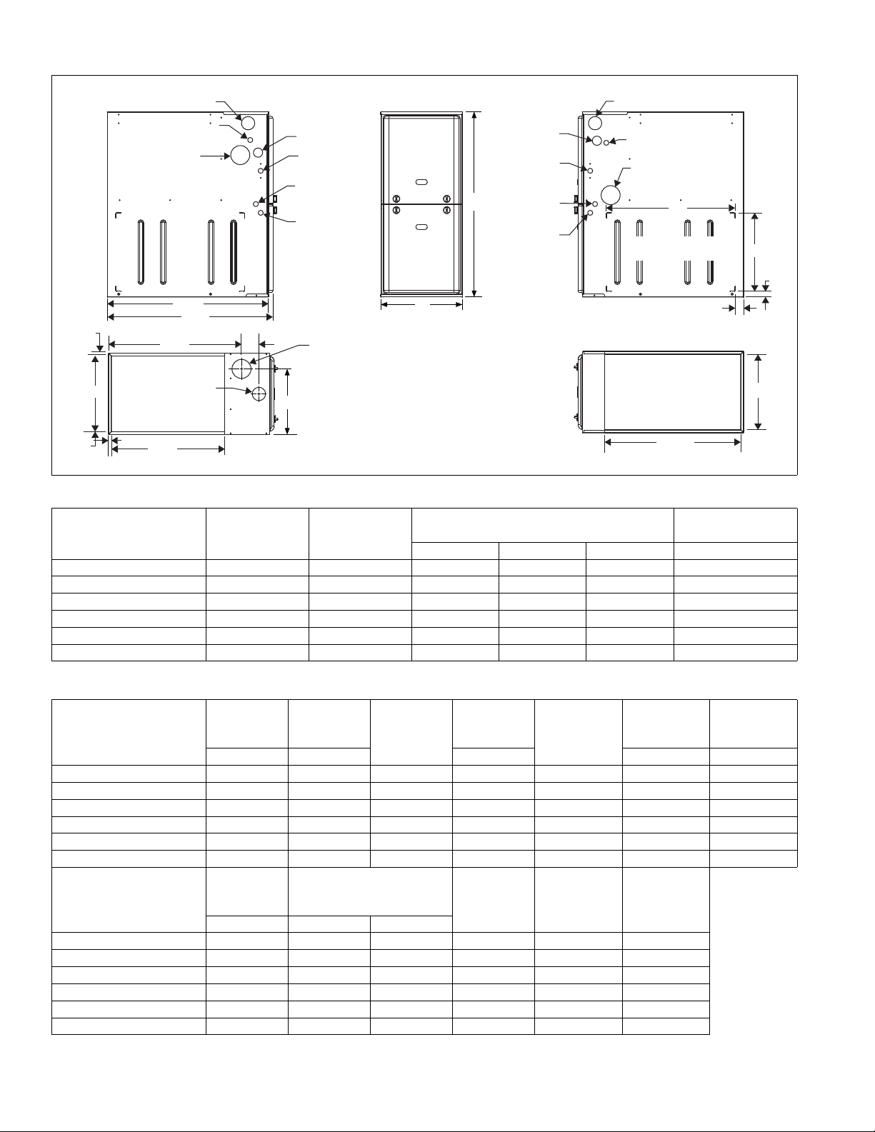
FRONT
33
A
LEFT SIDE
Combustion Air Inlet
Condensate Drain
(Downflow)
Thermostat
Wiring
28.5”
Gas Pipe
Entry
Electrical
Entry
Condensate
Drain
Thermostat
Wiring
RIGHT SIDE
Condensate Drain
(Downflow)
14”
1”
1.5”
23”
Combustion Air Inlet
Gas Pipe
Entry
Electrical
Entry
Condensate
Drain
Optional Return Air
Cutout (Either side)
29.5”
C
SUPPLY END
.56”
.56”
20”
B
3”
23.8”
.56”
Combustion
Air Inlet
RETURN END
B
24.25”
2” Vent
Connection
Outlet
2” Vent
Connection
Outlet
2” Vent
Connection
Outlet
Cabinet and Duct Dimensions
Approximate
Operating Weights
Models
Nominal
CFM (m
3
/min)
Cabinet
Size
Cabinet Dimensions (Inches)
A B C Lbs
TM9M060B12MP12 1200 B 17 1/2 16 3/8 13 1/4 122
TM9M080B12MP12 1200 B 17 1/2 16 3/8 14 3/4 126
TM9M080C16MP12 1600 C 21 19 7/8 16 1/2 136
TM9M100C16MP12 1600 C 21 19 7/8 18 1/4 142
TM9M100C20MP12 2000 C 21 19 7/8 18 1/4 145
TM9M120D20MP12 2000 D 24 1/2 23 3/8 21 3/4 156
Ratings & Physical / Electrical Data
Input
Models
TM9M060B12MP12 60/21 58/20 97.0 1200 10.0 40-70 20-50
TM9M080B12MP12 80/28 77/27 97.0 1200 10.0 45-75 20-50
TM9M080C16MP12 80/28 78/27 97.0 1600 11.5 45-75 25-55
TM9M100C16MP12 100/35 97/34 97.0 1600 11.5 40-70 25-55
TM9M100C20MP12 100/35 97/34 97.0 2000 17.0 45-75 20-50
TM9M120D20MP12 120/42 116/40 97.0 2000 17.0 45-75 25-55
Models
Max/Min
MBH MBH CFM °F °F
Max.
Outlet
Air Temp
°F HP Amps
Output
Max/Min
Blower
AFUE
%
Nominal
Airflow
Blower
Wheel
Size
Total
Unit
Amps
Max
Over-Current
Protect
Air Temp.
Rise Max
Input
Min. wire Size
(awg) @ 75 ft
one way
TM9M060B12MP12 175 1/2 7.0 11 x 8 15 14
TM9M080B12MP12 180 1/2 7.0 11 x 8 15 14
TM9M080C16MP12 180 3/4 8.8 11 x 10 15 14
TM9M100C16MP12 175 3/4 8.8 11 x 10 15 14
TM9M100C20MP12 180 1 14.5 11 x 11 20 12
TM9M120D20MP12 180 1 14.5 11 x 11 20 12
Annual Fuel Utilization Efficiency (AFUE) numbers are determined in accordance with DOE Test procedures.
Wire size and over current protection must comply with the National Electrical Code (NFPA-70-latest edition) and all local codes.
2 Johnson Controls Unitary Products
Air Temp.
Rise Min
Input
Page 3

563717-YTG-C-0713
FILTER PERFORMANCE
The airflow capacity data published in the “Blower Performance” table represents blower performance WITHOUT filters.
All applications of these furnaces require the use of field
installed air filters. All filter media and mounting hardware or
provisions must be field installed external to the furnace cabinet. DO NOT attempt to install any filters inside the furnace.
NOTE: Single side return above 1800 CFM is approved as long
as the filter velocity does not exceed filter manufacturer ’s recommendation and a transition is used to allow use of a 20 x 25
filter.
Recommended Filter Sizes
CFM
1200 B 16 x 25 16 x 25
1600 C 16 x 25 20 x 25
2000 D (2) 16 x 25 22 x 25
NOTES:
1. Air velocity through throwaway type filters may not exceed 300 feet per minute (91.4 m/min). All velocities over this require the use of high velocity filters.
2. Do not exceed 1800 CFM using a single side return and a 16x25 filter. For
CFM greater than 1800, you may use two side returns or one sid e and the
bottom or one return with a transition to allow use of a 20x25 filter.
Cabinet
Size
Side
(in)
Bottom
(in)
Unit Clearances to Combustibles
Application
Top 1" 0" 0"
Vent 0" 0" 0"
Rear 0" 0" 0"
Side 0" 0" 1"
1
Front
Floor Combustible
Closet Yes Yes Yes
Line Contact No No Yes
1.Line contact only permitted between lines formed by the intersection of the
rear panel and side panel (top in horizontal position) of the furnace jacket
and building joists, studs or framing.
2. For combustible floors only when used with special sub-base.
All furnaces approved for alcove and attic installation.
Upflow Downflow Horizontal
0" 0" 0"
2
Combustible
Combustible
ACCESSORIES
Propane (LP) Conversion Kit - This accessory conversion kit
may be used to convert natural gas (N) units for propane (LP)
operation.
1NP0681 - All Models
Concentric Vent Termination - For use through rooftop, sidewall. Allows combustion air to enter and exhaust to exit through
single common hole. Eliminates unslightly elbows for a cleaner
installation.
S1-1CT0302 (2")
S1-1CT0303 (3")
Sidewall Vent Termination Kit - For use on sidewall, two-pipe
installations only. Provide a more attractive termination for locations where the terminal is visable on the side of the home.
S1-1HT0901 (3")
S1-1HT0902 (2")
Condensate Neutralizer Kit - Neutralizer cartridge has a 1/2"
plastic tube fittings for installation in the drain line. Calcium carbonate refill media is also available from the Source 1 Parts (p/
n 026-30228-000).
1NK0301
Side Return Filter Racks -
1SR0200 - All Models
1SR0402 - All Models
Bottom Return Filter Racks - 1BR05xx series are galvanized
steel filter racks. 1BR06xx are pre-painted steel filter racks to
match the appearance of the furnace cabinet.
1BR0517 or 1BR0617 - For 17-1/2” cabinets
1BR0521 or 1BR0621 - For 21” cabinets
1BR0524 or 1BR0624 - For 24-1/2” cabinets
Combutible Floor Base Kit - For installation of these furnaces
in downflow applications directly onto combustible flooring
material, These kits are required to prevent potential overheating situations. These kits are also required in any applications
where the furnace in installed in a downflow configuration without an evaporator coil, where the combustible floor base kit provides access for combustible airflow.
1CB0517 - For 17-1/2” cabinets
1CB0521 - For 21” cabinets
1CB0524 - For 24-1/2” cabinets
High Altitude - No high altitude kits are required.
Thermostats - Compatible thermostat controls are available
through accessory sourcing. For optimum performance and
installation, refer to the UPGNET “Low Voltage Wiring Diagram”
document to select and apply controls.
Johnson Controls Unitary Products 3
Page 4

Blower Performance CFM - Any Position
Bottom Airflow Return (SCFM) (without filter)
Models Speed
High 1358 1341 1319 1303 1275 1238 1190 1130 1062 943
TM9M060B12MP12
Medium High 1097 1083 1075 1064 1042 1024 997 962 906 821
Medium Low 935 928 920 899 872 840 809 771 731 659
Low 800 779 763 736 711 687 657 622 584 529
High 1320 1327 1307 1281 1243 1197 1143 1075 1003 881
TM9M080B12MP12
Medium High 1003 981 975 954 926 895 865 824 751 687
Medium Low 821 818 809 786 758 726 690 631 594 534
Low 674 652 624 599 566 531 494 451 394 354
High 1881 1822 1783 1696 1602 1539 1465 1394 1267 1130
TM9M080C16MP12
Medium High 1553 1535 1492 1456 1408 1343 1279 1226 1113 1014
Medium Low 1312 1286 1288 1260 1205 1143 1091 1029 966 841
Low 1169 1166 1128 1098 1069 1032 987 909 835 747
High 2069 2014 1956 1885 1820 1748 1668 1577 1468 1362
TM9M100C16MP12
Medium High 1662 1656 1639 1608 1586 1544 1491 1421 1338 1204
Medium 1368 1371 1377 1376 1367 1334 1295 1250 1188 1104
Low 1016 1014 1018 1030 1012 996 975 944 898 852
High 2764 2695 2618 2552 2432 2337 2228 2109 1954 1808
TM9M100C20MP12
Medium High 2028 2009 1976 1910 1871 1830 1749 1679 1573 1473
Medium Low 1613 1600 1543 1533 1482 1433 1384 1316 1252 1160
Low 1297 1277 1245 1213 1175 1129 1077 1011 925 837
High 2701 2620 2533 2429 2338 2227 2112 1993 1861 1706
TM9M120D20MP12
Medium High 2125 2083 2046 1994 1955 1901 1857 1737 1621 1497
Medium Low 1664 1664 1547 1619 1580 1554 1468 1392 1331 1226
Low 1357 1339 1330 1318 1286 1235 1185 1141 1060 938
High 1244 1229 1226 1215 1196 1177 1143 1072 1015 940
TM9M060B12MP12
Medium High 1129 1126 1107 1094 1076 1047 1010 966 921 843
Medium Low 970 947 933 916 890 863 827 789 741 668
Low 834 809 797 768 740 710 677 634 586 534
High 1274 1285 1255 1239 1207 1158 1111 1049 979 830
TM9M080B12MP12
Medium High 975 974 968 960 948 923 879 823 756 672
Medium Low 777 771 772 762 752 734 695 651 604 529
Low 647 634 623 610 602 588 552 506 457 381
High 1825 1781 1746 1695 1641 1587 1521 1429 1330 1184
TM9M080C16MP12
Medium High 1516 1493 1482 1464 1442 1411 1343 1275 1192 1035
Medium 1294 1297 1271 1238 1187 1120 1083 1028 979 851
Low 1126 1115 1095 1049 1027 996 957 929 840 742
High 2009 1994 1933 1893 1836 1763 1691 1606 1508 1389
TM9M100C16MP12
Medium High 1523 1506 1521 1490 1466 1435 1393 1326 1241 1119
Medium Low 1230 1249 1245 1230 1218 1195 1161 1120 1039 949
Low 1126 1115 1095 1049 1027 996 957 929 840 742
High 2817 2774 2712 2620 2551 2465 2375 2266 2131 1992
TM9M100C20MP12
Medium High 1958 1946 1924 1901 1850 1813 1752 1675 1598 1502
Medium Low 1539 1523 1519 1491 1449 1395 1351 1270 1197 1098
Low 1276 1218 1229 1178 1126 1084 1017 958 890 819
High 2828 2768 2699 2612 2524 2423 2308 2219 2118 1982
TM9M120D20MP12
Medium High 2085 2073 2042 2029 1967 1896 1893 1816 1717 1635
Medium Low 1620 1631 1636 1593 1567 1557 1520 1476 1407 1263
Low 1322 1311 1302 1271 1241 1201 1162 1101 1042 979
NOTES:
1. Airflow expressed in standard cubic feet per minute (CFM).
2. Return air is through side opposite motor (left side) .
3. Motor voltage at 115 V.
4. Airflow through across motor side (right side) may be slightly less than the data shown above.
0.1 0.2 0.3 0.4 0.5 0.6 0.7 0.8 0.9 1.0
Left Side Airflow Return
(SCFM) - Upflow (without filter)
Ext. Static Pressure (in. H2O)
Subject to change without notice. Published in U.S.A. 563717-YTG-C-0713
Copyright © 2013 by Johnson Controls, Inc. All rights reserved. Supersedes: 563717-YTG-B-0512
York International Corp.
5005 York Drive
Norman, OK 73069
 Loading...