

Page 1
GAS-FIRED RESIDENTIAL
TECHNICAL
GUIDE
TECHNICAL
GUIDE
TWO STAGE PSC MULTI-POSITION
GAS FURNACES
STANDARD & Low NOx MODELS
MODELS: TM8T / TMLT
NATURAL GAS
60 - 120 MBH INPUT
Due to continuous product improvement,
specifications are subject to change without notice.
Visit us on the web at www.york.com for the most
up-to-date technical information.
Additional rating information can be found at
www.ahridirectory.org
WARRANTY
20-year limited warranty on the heat exchanger.
10-year heat exchanger warranty on commercial applications.
5-year limited parts warranty.
Extended 10-year limited parts warranty when product is
registered online within 90 days of purchase for
replacement or closing for new home construction.
521149-UTG-D-0715
DESCRIPTION
These compact units employ induced combustion, reliable hot
surface ignition and high heat transfer al uminized tubular heat
exchangers. The units are factory shipped for installation in
upflow or horizontal applications and may be converted for
downflow applications.
These furnaces are designed for residential installation in a
basement, closet, alcove, attic, recreation room or garage and
are also ideal for commercial applications. All units are factory
assembled, wired and tested to assure safe dependable and
economical installation and operation.
These units are Category I listed and may be common vented
with another gas appliance as allowed by the National Fuel Gas
Code.
FEATURES
• Two stage heating operation includes two stage gas valve,
two stage inducer operation and 4 speed PSC blower
operation. Adjustable delay timer allows two stage operation
with a single stage thermostat.
• Easily applied in upflow, horizontal left or right, or downflow
installation with minimal conversion necessary.
• Compact, easy to install, ideal height 33" tall cabinet.
• Blower-off delay for cooling SEER improvement.
• Easy access to controls to connect power/control wiring.
• Built-in, high level self diagnostics with fault code display.
• Low unit amp requirement for easy replacement application.
• All models are convertable to use propane (LP) gas.
• Electronic Hot Surface Ignition saves fuel cost with
increased dependability and reliability.
• 100% shut off main gas valve for extra safety.
• 24V, 40 VA control transformer and blower relay supplied for
add-on cooling.
• Hi-tech tubular aluminized steel primary heat exchanger.
• Solid removable bottom panel allows easy conversion.
• Airflow leakage less than 1% of nominal airflow for
ductblaster conditions.
• No knockouts to deal with, making installation easier.
• Movable duct connector flanges for application flexibility.
• Quiet inducer operation, burner, and blower operation.
• Inducer rotates for easy conversion of venting options.
• Fully supported blower assembly for easy access and
removal of blower.
• External air filters used for maximum flexibility in meeting
customers IAQ needs.
• Insulated blower compartment for thermal and acoustic
performance.
• Low NOx models have been designed to meet specific code
requirements.
• Venting applications - may be installed as a common vent
with other gas-fired appliances or use a masonry chimney.
• 1/4 turn knobs provided for easy independent door removal.
FOR DISTRIBUTION USE ONLY - NOT TO BE USED AT POINT OF RETAIL SALE
Page 2
521149-UTG-D-0715
LEFT SIDE
RIGHT SIDE
.5”
.5”
RETURN END
B
24.25”
29.5”
28.5”
Electrical
Entry
Gas Pipe
Entry
Thermostat
Wiring
FRONT
14”
1”
1.5”
23”
SUPPLY END
C
24.38”
20”
.5”
B
Gas Pipe
Entry
Thermostat
Wiring
33”
A
.5”
Electrical
Entry
Vent Connection
Outlet
Vent
Connection
Outlet
4” Diameter
Outlet
Vent Connection
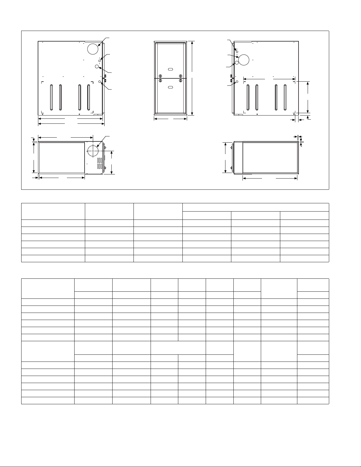
Cabinet and Duct Dimensions
Models
Nominal
CFM
Cabinet
Size
ABC
TM(8,L)T060A12MP11 1200 A 14 1/2 13 3/8 10.3
TM(8,L)T080B12MP11 1200 B 17 1/2 16 3/8 11.8
TM(8,L)T080C16MP11 1600 C 21 19 7/8 13.6
TM(8,L)T100C16MP11 1600 C 21 19 7/8 13.6
TM(8,L)T100C20MP11 2000 C 21 19 7/8 13.6
TM(8,L)T120C20MP11 2000 C 21 19 7/8 13.6
Table 1: Ratings & Physical / Electrical Data
Models
High Fire
Input
Low Fire
Input
High Fire
Output
Low Fire
Output
MBH MBH MBH MBH CFM % °F
TM(8,L)T060A12MP11 60 39 47 31 1200 80.0
TM(8,L)T080B12MP11 80 52 63 42 1200 80.0
TM(8,L)T080C16MP11 80 52 63 42 1600 80.0
TM(8,L)T100C16MP11 100 65 80 52 1600 80.0
TM(8,L)T100C20MP11 100 65 80 52 2000 80.0
TM(8,L)T120C20MP11 120 78 96 62 2000 80.0
Models
TM(8,L)T060A12MP11 30-60 15-45 1/3 4.8 11 x 8 7.0 14 94
TM(8,L)T080B12MP11 30-60 20-50 1/3 4.8 11 x 8 7.0 14 103
High Fire
Air Temp. Rise
°F °F HP Amps In. Lbs.
Low Fire
Air Temp. Rise
Blower
TM(8,L)T080C16MP11 30-60 20-50 1/2 7.0 11 x 10 10.0 14 114
TM(8,L)T100C16MP11 30-60 20-50 1/2 7.0 11 x 10 10.0 14 118
TM(8,L)T100C20MP11 30-60 20-50 1 14.5 11 x 11 17.0 12 122
TM(8,L)T120C20MP11 30-60 20-50 1 14.5 11 x 11 17.0 12 129
Annual Fuel Utilization Efficiency (AFUE) numbers are determined in accordance with DOE Test procedures.
Wire size and over current protection must comply with the National Electrical Code (NFPA-70-latest edition) and all local codes.
The furnace shall be installed so that the electrical components are protected from water.
Cabinet Dimensions (Inches)
Nominal
Airflow
AFUE
Blower
Size
Total Unit
Amps
Max.
Over-current
Protect
10
10
15
15
20
20
Min. wire Size
(awg) @ 75 ft
one way
Max. Outlet
Air Temp
Operating
weight
160
160
160
160
160
160
2 Johnson Controls Unitary Products
Page 3

521149-UTG-D-0715
NOTICE
HORIZONTAL SIDEWALL VENTING
For applications where vertical venting is not possible, the only
approved method of horizontal venting is the use of an auxiliary
power vent. Auxilary power venters must be approved by CSA,
UL, or other recognized safety agencies. Follow all application
and installation details provided by the manufacturer of the
power vent.
FILTER PERFORMANCE
The airflow capacity data published in the “Blower Performance” table shown represents blower performance WITHOUT
filters.
All applications of these furnaces require the use of field
installed air filters. All filter media and mounting hardware or
provisions must be field installed external to the furnace cabinet. DO NOT attempt to install any filters inside the furnace.
Unit Clearances to Combustibles (All dimensions in inche s, and all surfaces identified with the unit in an upflow configuration )
Single side return above 1800 CFM is appro ved as long as
the filter velocity does not exceed filter manufacturer’s recommendation and a transition is used to allow use on a
20x25 filter.
Recommended Filter Sizes
CFM
1200 A 16 x 25 14 x 25
1200 B 16 x 25 16 x 25
1600 C 16 x 25 20 x 25
2000 C (2) 16 x 25 20 x 25
1. Air velocity through throwaway type filters may not exceed 300 feet per minute (91.4 m/min). All velocities over this require the use of high velocity filters.
2. Do not exceed 1800 CFM using a single side return and a 16x25 filter. For
CFM greater than 1800, you may use two side returns or one side and the
bottom or one return with a transition to allow use of a 20x25 filter.
Cabinet
Size
Side
(in)
Bottom
(in)
Application Top Front Rear
Upflow 1 1 0 0 0 6 Combustible Yes Yes Yes No
Upflow B-Vent 1 1 0 0 0 1 Combustible Yes Yes Yes No
Downflow 1 1 0 0 0 6
Downflow B-Vent 1 1 0 0 0 1
Horizontal 1 1 0 0 0 6 Combustible No Yes Yes
Horizontal B-Vent 1 1 0 0 0 1 Combustible No Yes Yes
1. Special floor base or air conditioning coil required for use on combustible floor.
2. Line contact only permitted between lines formed by the inter section of the rear p anel an d side p anel (top in hori zont al position) of th e furnace jacket and building joists, studs or framing.
Left
Side
ACCESSORIES
Propane (LP) Conversion Kit -
1NP0347 - All Models
This accessory conversion kit may be used to convert natural
gas units for propane (LP) operation.
Side Return Filter Racks -
1SR0200 - All Models
1SR0302 - All Models
1SF0101 - All Models
Bottom Return Filter Racks -
1BR0514 or 1BR0614 - For 14-1/2” cabinets
1BR0517 or 1BR0617 - For 17-1/2” cabinets
1BR0521 or 1BR0621 - For 21” cabinets
1BR05xx series are galvanized steel filter racks. 1BR06xx are
pre-painted steel filter racks to match the appearance of the furnace cabinet.
Masonry Chimney Kits -
For installations where these furnaces are vented using existing
or new lined masonry chimneys.
Right
Side
Flue
Floor/
Bottom
1
1
1
1
Closet Alcove Attic
Yes Yes Yes No
Yes Yes Yes No
Line
Contact
Yes
Yes
Combustible Floor Base Kit -
For installation of these furnaces in downflow applications
directly onto combustible flooring material, These kits are
required to prevent potential overheating situations. These kits
are also required in any applications where the furnace in
installed in a downflow configuration without an evaporator coil,
where the combustible floor base kit provides access for combustible airflow.
1CB0514 - For 14-1/2” cabinets
1CB0517 - For 17-1/2” cabinets
1CB0521 - For 21” cabinets
High Altitude Pressure Switches -
For installation where the altitude is less than 5,000 feet it is not
required that the pressure switch be changed. For altitudes
above 5,000 feet, see kits below.
1PS3309
Thermostats - Compatible thermostat controls are available
through accessory sourcing. For optimum performance and
installation, refer to the UPGNET “Low Voltage Wiring Diagram”
document to select and apply controls.
1CK0603
1CK0604
2
2
Johnson Controls Unitary Products 3
Page 4

Blower Performance CFM - Any Position
Models Speed
0.1 0.2 0.3 0.4 0.5 0.6 0.7 0.8 0.9 1.0
Bottom Return (without filter)
High 1358 1341 1319 1303 1275 1238 1190 1130 1062 943
TM(8,L)T060A12MP11
TM(8,L)T080B12MP11
TM(8,L)T080C16MP11
TM(8,L)T100C16MP11
TM(8,L)T100C20MP11
TM(8,L)T120C20MP11
Medium High 1097 1083 1075 1064 1042 1024 997 962 906 821
Medium Low 935 928 920 899 872 840 809 771 731 659
Low 800 779 763 736 711 687 657 622 584 529
High 1329 1307 1285 1247 1195 1143 1091 1027 927 806
Medium High 994 1004 1008 984 970 941 893 839 773 669
Medium Low 786 790 782 781 761 743 726 685 630 540
Low 655 654 647 629 620 594 560 524 469 399
High 1881 1822 1783 1696 1602 1539 1465 1394 1267 1130
Medium High 1553 1535 1492 1456 1408 1343 1279 1226 1113 1014
Medium Low 1312 1286 1288 1260 1205 1143 1091 1029 966 841
Low 1169 1166 1128 1098 1069 1032 987 909 835 747
High 2069 2014 1956 1885 1820 1748 1668 1577 1468 1362
Medium High 1662 1656 1639 1608 1586 1544 1491 1421 1338 1204
Medium 1368 1371 1377 1376 1367 1334 1295 1250 1188 1104
Low 1016 1014 1018 1030 1012 996 975 944 898 852
High 2893 2774 2687 2589 2478 2376 2255 2120 1978 1824
Medium High 2272 2243 2204 2169 2086 2018 1940 1842 1743 1602
Medium Low 1765 1752 1737 1718 1674 1619 1561 1493 1437 1312
Low 1425 1380 1409 1378 1307 1274 1226 1180 1113 1025
High 2701 2620 2533 2429 2338 2227 2112 1993 1861 1706
Medium High 2125 2083 2046 1994 1955 1901 1857 1737 1621 1497
Medium Low 1664 1664 1647 1619 1580 1555 1468 1392 1332 1226
Low 1358 1339 1330 1318 1286 1235 1185 1141 1060 938
Left Side Return (without filter)
High 1406 1401 1394 1379 1338 1304 1261 1202 1135 1040
TM(8,L)T060A12MP11
TM(8,L)T080B12MP11
TM(8,L)T080C16MP11
TM(8,L)T100C16MP11
TM(8,L)T100C20MP11
TM(8,L)T120C20MP11
1. Airflow expressed in standard cubic feet per minute (CFM).
2. Motor voltage at 115 V.
3. Airflow through motor side (right side return) maybe slightly less than the data shown above.
Medium High 1129 1126 1107 1094 1076 1047 1010 966 921 843
Medium Low 970 947 933 916 890 863 827 789 741 668
Low 834 809 797 768 740 710 677 634 586 534
High 1274 1285 1255 1239 1207 1158 1111 1049 979 830
Medium High 975 974 968 960 948 923 879 823 756 672
Medium Low 777 771 772 762 752 734 695 651 604 529
Low 647 634 623 610 602 588 552 506 457 381
High 1825 1781 1746 1695 1641 1587 1521 1429 1330 1184
Medium High 1516 1493 1482 1464 1442 1411 1343 1275 1192 1035
Medium 1294 1297 1271 1238 1187 1120 1083 1028 979 851
Low 1126 1115 1095 1049 1027 996 957 929 840 742
High 2009 1994 1933 1893 1836 1763 1691 1606 1508 1389
Medium High 1523 1506 1521 1490 1466 1435 1393 1326 1241 1119
Medium Low 1230 1249 1245 1230 1218 1195 1161 1120 1039 949
Low 1126 1115 1095 1049 1027 996 957 929 840 742
High 2964 2886 2794 2707 2623 2522 2415 2281 2149 2012
Medium High 2192 2178 2150 2109 2098 2007 1956 1888 1795 1671
Medium Low 1699 1695 1706 1632 1612 1568 1519 1460 1392 1293
Low 1361 1356 1337 1304 1267 1243 1191 1149 1077 994
High 2828 2768 2699 2612 2524 2423 2308 2219 2118 1982
Medium High 2085 2073 2042 2029 1967 1896 1893 1816 1717 1635
Medium Low 1620 1631 1636 1593 1567 1557 1520 1476 1407 1263
Low 1322 1311 1302 1271 1241 1201 1162 1101 1042 979
Bottom Airflow Data (SCFM)
Ext. Static Pressure (in. H2O)
Subject to change without notice. Published in U.S.A. 521149-UTG-D-0715
Copyright © 2015 by Johnson Controls, Inc. All rights reserved. Supersedes: 521149-UTG-C-0612
York International Corp.
5005 York Drive
Norman, OK 73069
 Loading...