

York PREDATOR DM090 User Manual
INSTALLATION
MANUAL
CONTENTS
GENERAL . . . . . . . . . . . . . . . . . . . . . . . . . . . . . . . . . . . . .5
SAFETY CONSIDERATIONS . . . . . . . . . . . . . . . . . . . . . .5
INSPECTION . . . . . . . . . . . . . . . . . . . . . . . . . . . . . . . . . . .5
REFERENCE. . . . . . . . . . . . . . . . . . . . . . . . . . . . . . . . . . .5
APPROVALS. . . . . . . . . . . . . . . . . . . . . . . . . . . . . . . . . . .5
NOMENCLATURE . . . . . . . . . . . . . . . . . . . . . . . . . . . . . .6
INSTALLATION. . . . . . . . . . . . . . . . . . . . . . . . . . . . . . . .10
OPERATION . . . . . . . . . . . . . . . . . . . . . . . . . . . . . . . . . .33
START-UP (COOLING). . . . . . . . . . . . . . . . . . . . . . . . . .37
NORMAL MAINTENANCE . . . . . . . . . . . . . . . . . . . . . . .39
®
SINGLE PACKAGE AIR CONDITIONERS AND
SINGLE PACKAGE ELECTRIC UNITS
DM090, 120 and 150
7-1/2 TO 12-1/2 TON
(380V, 3 Phase, 60 HZ)
TROUBLESHOOTING . . . . . . . . . . . . . . . . . . . . . . . . . .39
See following pages for a complete Table of Contents.
NOTES, CAUTIONS AND WARNINGS
The installer should pay particular attention to the words:
NOTE, CAUTION, and WARNING. Notes
clarify or make the installation easier. Cautions
to prevent equipment damage. Warnings are given to alert
installer that personal injury and/or equipment damage
may result if installation procedure is not handled properly.
are intended to
are given
CAUTION: READ ALL SAFETY GUIDES BEFORE YOU
BEGIN TO INSTALL YOUR UNIT.
SAVE THIS MANUAL
035-17311-003-A-0704

TABLE OF CONTENTS
035-17311-003-A-0704
GENERAL . . . . . . . . . . . . . . . . . . . . . . . . . . . . . . . . . . . . . . 5
SAFETY CONSIDERATIONS . . . . . . . . . . . . . . . . . . . . . . . 5
INSPECTION . . . . . . . . . . . . . . . . . . . . . . . . . . . . . . . . . . . . 5
REFERENCE . . . . . . . . . . . . . . . . . . . . . . . . . . . . . . . . . . . . 5
APPROVALS . . . . . . . . . . . . . . . . . . . . . . . . . . . . . . . . . . . . 5
NOMENCLATURE . . . . . . . . . . . . . . . . . . . . . . . . . . . . . . . 6
INSTALLATION . . . . . . . . . . . . . . . . . . . . . . . . . . . . . . . . . 10
INSTALLATION SAFETY INFORMATION . . . . . . . . . . . . . 10
PRECEDING INSTALLATION . . . . . . . . . . . . . . . . . . . . . . . 10
LIMITATIONS . . . . . . . . . . . . . . . . . . . . . . . . . . . . . . . . . . . . 10
LOCATION . . . . . . . . . . . . . . . . . . . . . . . . . . . . . . . . . . . . . . 11
RIGGING AND HANDLING . . . . . . . . . . . . . . . . . . . . . . . . . 11
CLEARANCES . . . . . . . . . . . . . . . . . . . . . . . . . . . . . . . . . . . 12
DUCTWORK . . . . . . . . . . . . . . . . . . . . . . . . . . . . . . . . . . . . 15
DUCT COVERS . . . . . . . . . . . . . . . . . . . . . . . . . . . . . . . . . . 15
CONDENSATE DRAIN . . . . . . . . . . . . . . . . . . . . . . . . . . . . 16
COMPRESSORS . . . . . . . . . . . . . . . . . . . . . . . . . . . . . . . . . 16
FILTERS . . . . . . . . . . . . . . . . . . . . . . . . . . . . . . . . . . . . . . . 16
THERMOSTAT WIRING . . . . . . . . . . . . . . . . . . . . . . . . . . . 17
POWER AND CONTROL WIRING . . . . . . . . . . . . . . . . . . . 17
POWER WIRING DETAIL . . . . . . . . . . . . . . . . . . . . . . . . . . 17
OPTIONS/ACCESSORIES . . . . . . . . . . . . . . . . . . . . . . . . . 21
ELECTRIC HEAT ACCESSORIES . . . . . . . . . . . . . . . . . . . . . 21
ELECTRIC HEAT OPTION . . . . . . . . . . . . . . . . . . . . . . . . . . . 21
MOTORIZED OUTDOOR DAMPER . . . . . . . . . . . . . . . . . . . . 21
ECONOMIZER . . . . . . . . . . . . . . . . . . . . . . . . . . . . . . . . . . . . 22
POWER EXHAUST . . . . . . . . . . . . . . . . . . . . . . . . . . . . . . . . . 22
RAIN HOOD . . . . . . . . . . . . . . . . . . . . . . . . . . . . . . . . . . . . . . 22
ECONOMIZER AND POWER EXHAUST SET POINT
ADJUSTMENTS AND INFORMATION . . . . . . . . . . . . . . . 22
MINIMUM POSITION ADJUSTMENT . . . . . . . . . . . . . . . . . . .22
ENTHALPY SET POINT ADJUSTMENT . . . . . . . . . . . . . . . . . 22
POWER EXHAUST DAMPER SET POINT (WITH OR
WITHOUT POWER EXHAUST) . . . . . . . . . . . . . . . . . . . . . . . 22
INDOOR AIR QUALITY AQ . . . . . . . . . . . . . . . . . . . . . . . . . . . 22
PHASING . . . . . . . . . . . . . . . . . . . . . . . . . . . . . . . . . . . . . . . 24
BLOWER ROTATION . . . . . . . . . . . . . . . . . . . . . . . . . . . . . 24
BELT TENSION . . . . . . . . . . . . . . . . . . . . . . . . . . . . . . . . . . 24
AIR BALANCE . . . . . . . . . . . . . . . . . . . . . . . . . . . . . . . . . . . 31
CHECKING AIR QUANTITY . . . . . . . . . . . . . . . . . . . . . . . . 31
METHOD ONE . . . . . . . . . . . . . . . . . . . . . . . . . . . . . . . . . . . . .31
METHOD TWO . . . . . . . . . . . . . . . . . . . . . . . . . . . . . . . . . . . .31
SUPPLY AIR DRIVE ADJUSTMENT . . . . . . . . . . . . . . . . . 32
OPERATION . . . . . . . . . . . . . . . . . . . . . . . . . . . . . . . . . . . 33
SEQUENCE OF OPERATIONS OVERVIEW . . . . . . . . . . . 33
COOLING SEQUENCE OF OPERATION . . . . . . . . . . . . . . 34
CONTINUOUS BLOWER . . . . . . . . . . . . . . . . . . . . . . . . . . . . .34
INTERMITTENT BLOWER . . . . . . . . . . . . . . . . . . . . . . . . . . .34
NO OUTDOOR AIR OPTIONS . . . . . . . . . . . . . . . . . . . . . . . .34
ECONOMIZER WITH SINGLE ENTHALPY SENSOR - . . . . .34
ECONOMIZER WITH DUAL ENTHALPY SENSORS - . . . . . .34
ECONOMIZER WITH POWER EXHAUST - . . . . . . . . . . . . . .34
MOTORIZED OUTDOOR AIR DAMPERS - . . . . . . . . . . . . . .34
COOLING OPERATION ERRORS . . . . . . . . . . . . . . . . . . . . .35
HIGH-PRESSURE LIMIT SWITCH . . . . . . . . . . . . . . . . . . . . .35
LOW-PRESSURE LIMIT SWITCH . . . . . . . . . . . . . . . . . . . . . .35
FREEZESTAT . . . . . . . . . . . . . . . . . . . . . . . . . . . . . . . . . . . . .35
LOW AMBIENT COOLING . . . . . . . . . . . . . . . . . . . . . . . . . . . .35
SAFETY CONTROLS . . . . . . . . . . . . . . . . . . . . . . . . . . . . . 35
COMPRESSOR PROTECTION . . . . . . . . . . . . . . . . . . . . . 35
FLASH CODES . . . . . . . . . . . . . . . . . . . . . . . . . . . . . . . . . . . .36
RESET . . . . . . . . . . . . . . . . . . . . . . . . . . . . . . . . . . . . . . . . . . .36
ELECTRIC HEATING SEQUENCE OF OPERATIONS . . . 36
ELECTRIC HEATING OPERATION ERRORS . . . . . . . . . . 36
TEMPERATURE LIMIT . . . . . . . . . . . . . . . . . . . . . . . . . . . . . .36
SAFETY CONTROLS . . . . . . . . . . . . . . . . . . . . . . . . . . . . . . .36
LIMIT SWITCH (LS) . . . . . . . . . . . . . . . . . . . . . . . . . . . . . . . . .36
FLASH CODES . . . . . . . . . . . . . . . . . . . . . . . . . . . . . . . . . . . .36
RESET . . . . . . . . . . . . . . . . . . . . . . . . . . . . . . . . . . . . . . . . . . .36
ELECTRIC HEAT ANTICTPATOR SETPOINTS . . . . . . . . . 36
START-UP (COOLING) . . . . . . . . . . . . . . . . . . . . . . . . . . 37
PRESTART CHECK LIST . . . . . . . . . . . . . . . . . . . . . . . . . . 37
OPERATING INSTRUCTIONS . . . . . . . . . . . . . . . . . . . . . . 37
POST START CHECK LIST . . . . . . . . . . . . . . . . . . . . . . . . 37
CHARGING THE UNIT . . . . . . . . . . . . . . . . . . . . . . . . . . . 37
NORMAL MAINTENANCE . . . . . . . . . . . . . . . . . . . . . . . . 39
GENERAL . . . . . . . . . . . . . . . . . . . . . . . . . . . . . . . . . . . . . . 39
FILTERS . . . . . . . . . . . . . . . . . . . . . . . . . . . . . . . . . . . . . . . . . .39
MOTORS . . . . . . . . . . . . . . . . . . . . . . . . . . . . . . . . . . . . . . . . .39
OUTDOOR COIL . . . . . . . . . . . . . . . . . . . . . . . . . . . . . . . . . . .39
TROUBLESHOOTING . . . . . . . . . . . . . . . . . . . . . . . . . . 39
PREDATOR® FLASH CODES . . . . . . . . . . . . . . . . . . . . . . 39
COOLING TROUBLESHOOTING GUIDE . . . . . . . . . . . . . . 41
2 Unitary Products Group

035-17311-003-A-0704
LIST OF FIGURES
Fig. # Pg.#
1 UNIT SHIPPING BRACKET . . . . . . . . . . . . . . . . . . . . 10
2 CONDENSER COVERING . . . . . . . . . . . . . . . . . . . . 10
3 COMPRESSOR SECTION . . . . . . . . . . . . . . . . . . . . . 10
4 PREDATOR® COMPONENT LOCATION . . . . . . . . . 11
5 UNIT 4 POINT LOAD . . . . . . . . . . . . . . . . . . . . . . . . . 12
6 UNIT 6 POINT LOAD . . . . . . . . . . . . . . . . . . . . . . . . . 12
7 UNIT CENTER OF GRAVITY . . . . . . . . . . . . . . . . . . . 12
8 UNIT DIMENSIONS . . . . . . . . . . . . . . . . . . . . . . . . . . 13
9 BOTTOM DUCT OPENINGS (FROM ABOVE) . . . . . 14
10 REAR DUCT DIMENSIONS . . . . . . . . . . . . . . . . . . . . 14
11 PREDATOR® ROOF CURB DIMENSIONS . . . . . . . . 15
12 SUNLINE™ TO PREDATOR® TRANSITION ROOF
CURBS . . . . . . . . . . . . . . . . . . . . . . . . . . . . . . . . . . . . 15
Fig. #
13 SIDE PANELS WITH HOLE PLUGS . . . . . . . . . . . . . 16
14 RETURN DOWNFLOW PLENUM WITH PANEL . . . 16
15 DISCHARGE PANEL IN PLACE . . . . . . . . . . . . . . . . 16
16 CONDENSATE DRAIN . . . . . . . . . . . . . . . . . . . . . . . 16
17 ELECTRONIC THERMOSTAT FIELD WIRING . . . . 18
18 FIELD WIRING 24 VOLT THERMOSTAT . . . . . . . . . 18
19 FIELD WIRING DISCONNECT . . . . . . . . . . . . . . . . . 19
20 ENTHALPY SET POINT CHART . . . . . . . . . . . . . . . . 23
21 HONEYWELL ECONOMIZER CONTROL W7212 . . 23
22 BELT ADJUSTMENT . . . . . . . . . . . . . . . . . . . . . . . . . 24
23 DRY COIL DELTA P . . . . . . . . . . . . . . . . . . . . . . . . . 32
24 BASIC TROUBLESHOOTING FLOWCHART . . . . . . 40
Pg.#
Unitary Products Group 3

LIST OF TABLES
035-17311-003-A-0704
Tbl.# Pg.#
1 UNIT VOLTAGE LIMITATIONS . . . . . . . . . . . . . . . . . 11
2 UNIT TEMPERATURE LIMITATIONS . . . . . . . . . . . . 11
3 UNIT WEIGHTS . . . . . . . . . . . . . . . . . . . . . . . . . . . . . 12
4 6 POINT LOAD WEIGHT . . . . . . . . . . . . . . . . . . . . . .12
5 4 POINT LOAD WEIGHT . . . . . . . . . . . . . . . . . . . . . .12
6 UNIT CLEARANCES . . . . . . . . . . . . . . . . . . . . . . . . . 13
7 CONTROL WIRE SIZES . . . . . . . . . . . . . . . . . . . . . . . 17
8 ELECTRICAL DATA - DM090 (7-1/2 TON) WITHOUT
POWER CONVENIENCE OUTLET . . . . . . . . . . . . . . 19
9 ELECTRICAL DATA - DM090 (7-1/2 TON) WITH
POWER CONVENIENCE OUTLET . . . . . . . . . . . . . . 19
10 ELECTRICAL DATA - DM120 (10 TON) WITHOUT
POWER CONVENIENCE OUTLET . . . . . . . . . . . . . . 20
11 ELECTRICAL DATA - DM120 (10 TON) WITH POWER
CONVENIENCE OUTLET . . . . . . . . . . . . . . . . . . . . . 20
12 ELECTRICAL DATA - DM150 (12-1/2 TON) WITHOUT
POWER CONVENIENCE OUTLET . . . . . . . . . . . . . . 20
13 ELECTRICAL DATA - DM150 (12-1/2 TON) WITH
POWER CONVENIENCE OUTLET . . . . . . . . . . . . . . 20
14 PHYSICAL DATA . . . . . . . . . . . . . . . . . . . . . . . . . . . . 21
15 MINIMUM SUPPLY AIR CFM . . . . . . . . . . . . . . . . . . . 21
16 SUPPLY AIR LIMITATIONS . . . . . . . . . . . . . . . . . . . . 24
17 7-1/2 TON STANDARD MOTOR DOWN SHOT
BLOWER PERFORMANCE . . . . . . . . . . . . . . . . . . . 25
18 7-1/2 TON OPTIONAL MOTOR DOWN SHOT
BLOWER PERFORMANCE . . . . . . . . . . . . . . . . . . . 25
19 10 TON STANDARD MOTOR DOWN SHOT
BLOWER PERFORMANCE . . . . . . . . . . . . . . . . . . . 26
Tbl.#
20 10 TON OPTIONAL MOTOR DOWN SHOT
BLOWER PERFORMANCE . . . . . . . . . . . . . . . . . . . 26
21 12-1/2 TON STANDARD MOTOR DOWN SHOT
BLOWER PERFORMANCE . . . . . . . . . . . . . . . . . . . 27
22 12-1/2 TON OPTIONAL MOTOR DOWN SHOT
BLOWER PERFORMANCE . . . . . . . . . . . . . . . . . . . 27
23 7-1/2 TON STANDARD MOTOR SIDE SHOT
BLOWER PERFORMANCE . . . . . . . . . . . . . . . . . . . 28
24 7-1/2 TON OPTIONAL MOTOR SIDE SHOT
BLOWER PERFORMANCE . . . . . . . . . . . . . . . . . . . 28
25 10 TON STANDARD MOTOR DOWN SHOT
BLOWER PERFORMANCE . . . . . . . . . . . . . . . . . . . 29
26 10 TON OPTIONAL MOTOR DOWN SHOT
BLOWER PERFORMANCE . . . . . . . . . . . . . . . . . . . 29
27 12-1/2 TON STANDARD MOTOR SIDE SHOT
BLOWER PERFORMANCE . . . . . . . . . . . . . . . . . . . 30
28 12-1/2 TON OPTIONAL MOTOR SIDE SHOT
BLOWER PERFORMANCE . . . . . . . . . . . . . . . . . . . 30
29 INDOOR BLOWER SPECIFICATIONS . . . . . . . . . . . 31
30 ADDITIONAL STATIC RESISTANCE . . . . . . . . . . . . 33
31 MOTOR SHEAVE DATUM DIAMETERS . . . . . . . . . . 33
32 ELECTRIC HEAT LIMIT SETTING . . . . . . . . . . . . . . 36
33 ELECTRIC HEAT ANTICIPATOR SETPOINTS . . . . 36
34 7.5 TON STANDARD EFFICIENCY SUPERHEAT
CHARGING . . . . . . . . . . . . . . . . . . . . . . . . . . . . . . . . 37
35 10 TON STANDARD EFFICIENCY SUPERHEAT
CHARGING . . . . . . . . . . . . . . . . . . . . . . . . . . . . . . . . 38
36 12.5 TON STANDARD EFFICIENCY SUPERHEAT
CHARGING . . . . . . . . . . . . . . . . . . . . . . . . . . . . . . . . 38
37 UNIT CONTROL BOARD FLASH CODES . . . . . . . . 40
Pg.#
4 Unitary Products Group
035-17311-003-A-0704
GENERAL
YORK® Predator® units are single package air conditioners
designed for outdoor installation on a rooftop or slab and for
non-residential use. These units can be equipped with factory
or field installed electric heaters for heating applications.
These units are completely assembled on rigid, permanently
attached base rails. All piping, refrigerant charge, and electrical wiring is factory installed and tested. The units require
electric power and duct connections. The electric heaters
have nickel-chrome elements and utilize single-point power
connection.
SAFETY CONSIDERATIONS
Due to system pressure, moving parts, and electrical components, installation and servicing of air conditioning equipment
can be hazardous. Only qualified, trained service personnel
should install, repair, or service this equipment. Untrained
personnel can perform basic maintenance functions of cleaning coils and filters and replacing filters.
Observe all precautions in the literature, labels, and tags
accompanying the equipment whenever working on air conditioning equipment. Be sure to follow all other applicable
safety precautions and codes.
Wear safety glasses and work gloves. Use quenching cloth
and have a fire extinguisher available during brazing operations.
INSPECTION
REFERENCE
Additional information is available in the following reference
forms:
• General Installation - DM090 - 150, 035-17311-002
• Pre-start & Post-start Check List - 035-18466-000
• Economizer Accessory Downflow Factory Installed, 035-18286-000
Downflow Field Installed, 035-18285-000
Horizontal Field Installed, 035-18287-000
• Motorized Outdoor Air Damper 035-18283-000
• Manual Outdoor Air Damper (0-100%) 035-18282-000
• Manual Outdoor Air Damper (0-35%) 035-18281-000
• Electric Heater Accessory 035-17291-001
• Unit Renewal Parts List 035-17288-000
APPROVALS
Design certified by CSA as follows:
1. For use as a cooling only unit, cooling unit with supplemental electric heat or a forced air furnace.
2. For outdoor installation only.
3. For installation on combustible material and may be
installed directly on combustible flooring or, in the U.S.,
on wood flooring or Class A, Class B or Class C roof covering materials .
As soon as a unit is received, it should be inspected for possible damage during transit. If damage is evident, the extent of
the damage should be noted on the carrier’s freight bill. A
separate request for inspection by the carrier’s agent should
be made in writing.
This furnace is not to be used for temporary heating
of buildings or structures under construction.
Before performing service or maintenance operations on unit, turn off main power switch to unit. Electrical shock could cause personal injury. Improper
installation, adjustment, alteration, service or maintenance can cause injury or property damage. Refer
to this manual. For assistance or additional information consult a qualified installer, service agency.
This product must be installed in strict compliance
with the enclosed installation instructions and any
applicable local, state, and national codes including,
but not limited to, building, electrical, and mechanical
codes.
Incorrect installation may create a condition where the
operation of the product could cause personal injury
or property damage.
The installer should pay particular attention to the words:
NOTE, CAUTION, and WARNING. NOTES are intended to
clarify or make the installation easier. CAUTIONS are given
to prevent equipment damage. WARNINGS are given to alert
installer that personal injury and/or equipment damage may
result if installation procedure is not handled properly.
Unitary Products Group 5
NOMENCLATURE
6½ - 12½ Ton Predator Model Number Nomenclature
035-17311-003-A-0704
D M C00
Product Category
D = Air Cond., Single Package
Product Identifier
M = R-22 Standard Efficiency
Nominal Cooling Capacity - MBH
090 = 7-½ Ton
120 = 10 Ton
150 = 12-½ Ton
Heat Type & Nominal Heat Capacity
C00 = Cooling Only. Suitable for field installed electric heat
Electric Heat Options
E09 = 9 kW Electric Heat
E18 = 18 kW Electric Heat
E24 = 24 kW Electric Heat
E36 = 36 kW Electric Heat
E54 = 54 kW Electric Heat
Voltage
3 = 380-3-60
AA 3090
A3A
Product Generation
3 = Third Generation
4 = Fourth Generation
Installation Options
A = No Options Installed
B = Option 1
C = Option 2
D = Options 1 & 2
E = Option 3
F = Option 4
G = Options 1 & 3
H = Options 1 & 4
J = Options 1, 2 & 3
K = Options 1, 2 & 4
L = Options 1, 3 & 4
M = Options 1, 2, 3 & 4
N = Options 2 & 3
P = Options 2 & 4
Q = Options 2, 3 & 4
R = Options 3 & 4
S = Option 5
T = Options 1 & 5
U = Options 1, 3 & 5
V = Options 1, 4 & 5
W = Options 1, 3, 4 & 5
X = Options 3 & 5
Y = Options 4 & 5
Z = Options 3, 4 & 5
Additional Options
(See Next Page)
Options
1 = Disconnect
2 = Non-Pwr’d Conv Outlet
3 = Smoke Detector S. A.
4 = Smoke Detector R. A.
5 = Pwr’d Conv Outlet
Airflow
A = Standard Motor
B = Standard Motor/Economizer/Barometric Relief (Downflow only)
C = Standard Motor/Economizer/Power Exhaust (Downflow only)
D = Standard Motor/Motorized Damper (Downflow only)
E = Standard Motor/Horizontal Economizer (No Barometric Relief or Power Exhaust)
F = Standard Motor/Slab Economizer/Power Exhaust (Downflow only)
G = Standard Motor/Slab Economizer/Barometric Relief (Downflow only)
L = Standard Motor/BAS Ready Econ (NoBASController)/Barometric Relief w/2" Pleated Filters (Downflow only)
M = Standard Motor/BAS Ready Econ (NoBASController)/Power Exhaust w/2" Pleated Filters (Downflow only)
N = High Static Motor
P = High Static Motor/Economizer/Barometr ic Relief (Downflow only)
Q = High Static Motor/Economizer/Power Exhaust (Downflow only)
R = High Static Motor/Motorized Damper (Downflow only)
S = High Static Motor/Horizontal Economizer (No Barometric Relief or Power Exhaust)
T = High Static Motor/Slab Economizer/Power Exhaust (Downflow only)
U =High Static Motor/Slab Economizer/Barometric Relief (Downflow only)
Y = High Static Motor/BAS Ready Econ (NoBASController)/Barometric Relief w/2" Pleated Filters (Downflow only)
Z = High Static Motor/BAS Ready Econ (NoBASController)/Power Exhaust w/2" Pleated Filters (Downflow only)
6 Unitary Products Group

035-17311-003-A-0704
NOMENCLATURE, ADDITONAL OPTIONS:
AA None
AB Phase Monitor
AC Coil Guard
AD Dirty Filter Switch
AE Phase Monitor & Coil Guard
AF Phase Monitor & Dirty Filter Switch
AG Coil Guard & Dirty Filter Switch
AH Phase Monitor, Coil Guard, & Dirty Filter Switch
CA CPC Controller with Dirty Filter Switch & Air Proving Switch
CB CPC Controller, DFS, APS & Phase Monitor
CC CPC Controller, DFS, APS & Coil Guard
CD CPC Controller, DFS, APS, Phase Monitor, & Coil Guard
CE CPC Controller, DFS, APS & Technicoat Cond. Coil
CF CPC Controller, DFS, APS, Technicoat Cond. Coil, & Phase Monitor
CG CPC Controller, DFS, APS, Technicoat Cond. Coil, & Coil Guard
CH CPC Controller, DFS, APS, Technicoat Cond. Coil, Phase Monitor, & Coil Guard
CJ CPC Controller, DFS, APS & Technicoat Evap. Coil
CK CPC Controller, DFS, APS, Technicoat Evap. Coil, & Phase Monitor
CL CPC Controller, DFS, APS, Technicoat Evap. Coil, & Coil Guard
CM CPC Controller, DFS, APS, Technicoat Evap. Coil, Phase Monitor, & Coil Guard
CN CPC Controller, DFS, APS & Technicoat Evap. & Cond Coils
CP CPC Controller, DFS, APS, Technicoat Evap. & Cond Coils, & Phase Monitor
CQ CPC Controller, DFS, APS, Technicoat Evap. & Cond Coils, & Coil Guard
CR CPC Controller, DFS, APS, Technicoat Cond Coils, Phase Monitor, & 2” Pleated Filters
CV CPC Controller, DFS, APS, & 2” Pleated Filters
CX CPC Controller, DFS, APS, Technicoat Evap. & Cond Coils, Phase Monitor, Coil Guard
HA Honeywell Excel 10 Controller with Dirty Filter Switch & Air Proving Switch
HB Honeywell Excel 10 Controller, DFS, APS & Phase Monitor
HC Honeywell Excel 10 Controller, DFS, APS & Coil Guard
HD Honeywell Excel 10 Controller, DFS, APS, Phase Monitor, & Coil Guard
HE Honeywell Excel 10 Controller, DFS, APS & Technicoat Cond. Coil
HF Honeywell Excel 10 Controller, DFS, APS, Technicoat Cond. Coil, & Phase Monitor
HG Honeywell Excel 10 Controller, DFS, APS, Technicoat Cond. Coil, & Coil Guard
HH Honeywell Excel 10 Controller, DFS, APS, Technicoat Cond. Coil, Phase Monitor, & Coil Guard
HJ Honeywell Excel 10 Controller, DFS, APS & Technicoat Evap. Coil
HK Honeywell Excel 10 Controller, DFS, APS, Technicoat Evap. Coil, & Phase Monitor
HL Honeywell Excel 10 Controller, DFS, APS, Technicoat Evap. Coil, & Coil Guard
HM Honeywell Excel 10 Controller, DFS, APS, Technicoat Evap. Coil, Phase Monitor, & Coil Guard
Unitary Products Group 7

HN Honeywell Excel 10 Controller, DFS, APS & Technicoat Evap. & Cond Coils
HP Honeywell Excel 10 Controller, DFS, APS, Technicoat Evap. & Cond Coils, & Phase Monitor
HQ Honeywell Excel 10 Controller, DFS, APS, Technicoat Evap. & Cond Coils, & Coil Guard
HR Honeywell Excel 10 Controller, DFS, APS, Technicoat Evap. & Cond Coils, Phase Monitor, & Coil Guard
JA Johnson UNT Controller with Dirty Filter Switch & Air Proving Switch
JB Johnson UNT Controller, DFS, APS & Phase Monitor
JC Johnson UNT Controller, DFS, APS & Coil Guard
JD Johnson UNT Controller, DFS, APS, Phase Monitor, & Coil Guard
JE Johnson UNT Controller, DFS, APS & Technicoat Cond. Coil
JF Johnson UNT Controller, DFS, APS, Technicoat Cond. Coil, & Phase Monitor
JG Johnson UNT Controller, DFS, APS, Technicoat Cond. Coil, & Coil Guard
JH Johnson UNT Controller, DFS, APS, Technicoat Cond. Coil, Phase Monitor, & Coil Guard
JJ Johnson UNT Controller, DFS, APS & Technicoat Evap. Coil
JK Johnson UNT Controller, DFS, APS, Technicoat Evap. Coil, & Phase Monitor
JL Johnson UNT Controller, DFS, APS, Technicoat Evap. Coil, & Coil Guard
JM Johnson UNT Controller, DFS, APS, Technicoat Evap. Coil, Phase Monitor, & Coil Guard
JN Johnson UNT Controller, DFS, APS & Technicoat Evap. & Cond Coils
JP Johnson UNT Controller, DFS, APS, Technicoat Evap. & Cond Coils, & Phase Monitor
JQ Johnson UNT Controller, DFS, APS, Technicoat Evap. & Cond Coils, & Coil Guard
JR Johnson UNT Controller, DFS, APS, Technicoat Evap. & Cond Coils, Phase Monitor, & Coil Guard
NA Novar ETC-3 Controller with Dirty Filter Switch & Air Proving Switch
NB Novar ETC-3 Controller, DFS, APS & Phase Monitor
NC Novar ETC-3 Controller, DFS, APS & Coil Guard
ND Novar ETC-3 Controller, DFS, APS, Phase Monitor, & Coil Guard
NE Novar ETC-3 Controller, DFS, APS & Technicoat Cond. Coil
NF Novar ETC-3 Controller, DFS, APS, Technicoat Cond. Coil, & Phase Monitor
NG Novar ETC-3 Controller, DFS, APS, Technicoat Cond. Coil, & Coil Guard
NH Novar ETC-3 Controller, DFS, APS, Technicoat Cond. Coil, Phase Monitor, & Coil Guard
NJ Novar ETC-3 Controller, DFS, APS & Technicoat Evap. Coil
NK Novar ETC-3 Controller, DFS, APS, Technicoat Evap. Coil, & Phase Monitor
NL Novar ETC-3 Controller, DFS, APS, Technicoat Evap. Coil, & Coil Guard
NM Novar ETC-3 Controller, DFS, APS, Technicoat Evap. Coil, Phase Monitor, & Coil Guard
NN Novar ETC-3 Controller, DFS, APS & Technicoat Evap. & Cond Coils
NP Novar ETC-3 Controller, DFS, APS, Technicoat Evap. & Cond Coils, & Phase Monitor
NQ Novar ETC-3 Controller, DFS, APS, Technicoat Evap. & Cond Coils, & Coil Guard
NR Novar ETC-3 Controller, DFS, APS, Technicoat Evap. & Cond Coils, Phase Monitor, & Coil Guard
TA Technicoat Condenser Coil
TB Technicoat Condenser Coil & Phase Monitor
TC Technicoat Condenser Coil & Coil Guard
TD Technicoat Condenser Coil & Dirty Filter Switch
035-17311-003-A-0704
8 Unitary Products Group

035-17311-003-A-0704
TE Technicoat Condenser Coil, Phase Monitor, & Coil Guard
TF Technicoat Condenser Coil, Phase Monitor, & Dirty Filter Switch
TG Technicoat Condenser Coil, Coil Guard, & Dirty Filter Switch
TH Technicoat Condenser Coil, Phase Monitor, Coil Guard, & Dirty Filter Switch
TJ Technicoat Evaporator Coil
TK Technicoat Evaporator Coil & Phase Monitor
TL Technicoat Evaporator Coil & Coil Guard
TM Technicoat Evaporator Coil & Dirty Filter Switch
TN Technicoat Evaporator Coil, Phase Monitor, & Coil Guard
TP Technicoat Evaporator Coil, Phase Monitor, & Dirty Filter Switch
TQ Technicoat Evaporator Coil, Coil Guard, & Dirty Filter Switch
TR Technicoat Evaporator Coil, Phase Monitor, Coil Guard, & Dirty Filter Switch
TS Technicoat Evaporator & Condenser Coils
TT Technicoat Evaporator & Condenser Coils & Phase Monitor
TU Technicoat Evaporator & Condenser Coils & Coil Guard
TV Technicoat Evaporator & Condenser Coils & Dirty Filter Switch
TW Technicoat Evaporator & Condenser Coils, Phase Monitor, & Coil Guard
TX Technicoat Evaporator & Condenser Coils, Phase Monitor, & Dirty Filter Switch
TY Technicoat Evaporator & Condenser Coils, Coil Guard, & Dirty Filter Switch
TZ Technicoat Evaporator & Condenser Coils, Phase Monitor, Coil Guard, & Dirty Filter Switch
Unitary Products Group 9
035-17311-003-A-0704
INSTALLATION
INSTALLATION SAFETY INFORMATION
Read these instructions before continuing this appliance
installation. This is an outdoor combination heating and cooling unit. The installer must assure that these instructions are
made available to the consumer and with instructions to
retain them for future reference.
1. Install this furnace only in a location and position as
specified on Page 11 of these instructions.
2. This equipment is not to be used for temporary heating
of buildings or structures under construction.
PRECEDING INSTALLATION
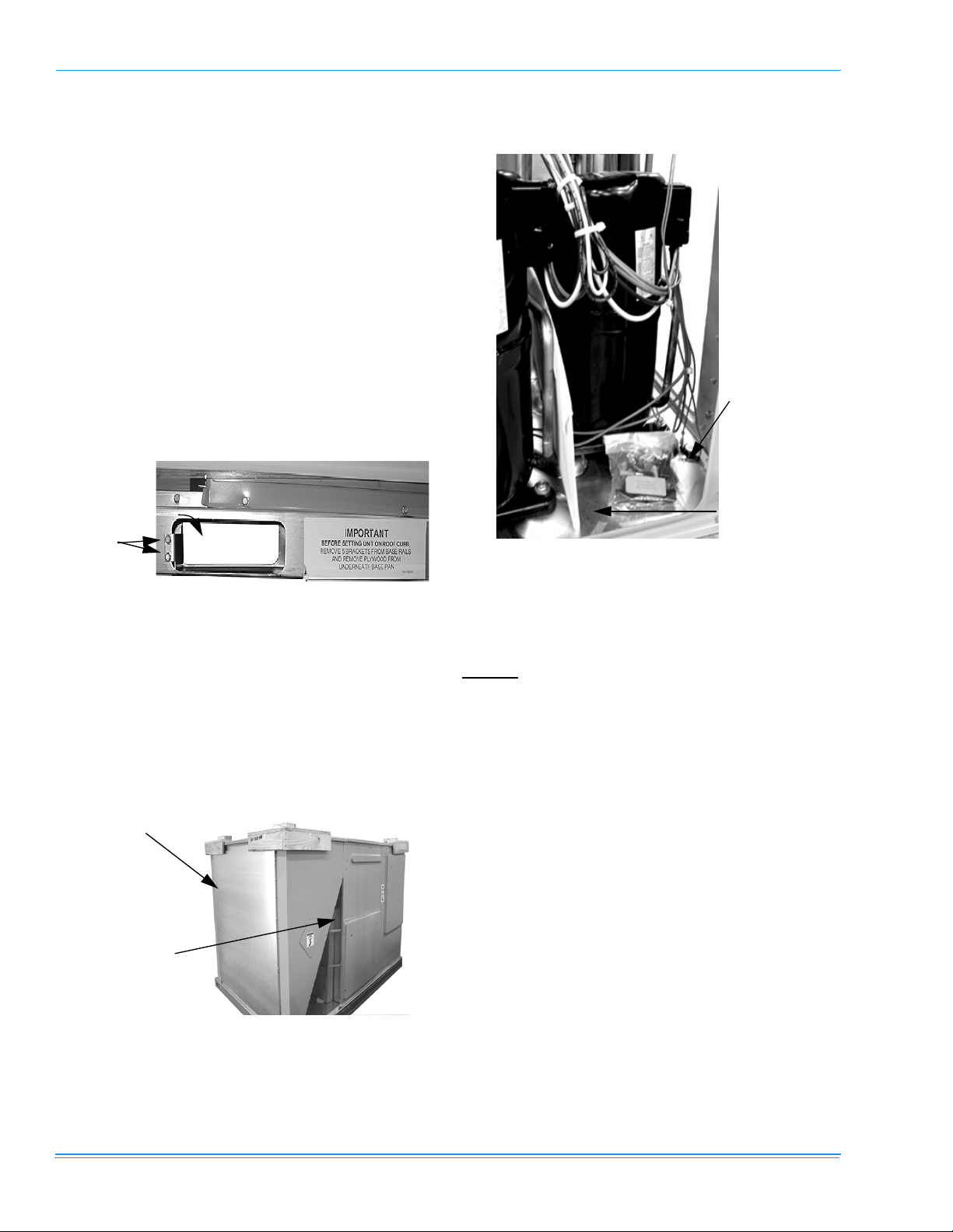
1. Remove the two screws holding the brackets in the front,
rear and compressor side fork-lift slots.
Bracket
Screws
Turn down
Toolless
Doorknobs
Installation
Instruction
Packet
FIGURE 3 - COMPRESSOR SECTION
FIGURE 1 - UNIT SHIPPING BRACKET
2. Turn each bracket toward the ground and the protective
plywood covering will drop to the ground.
3. Remove the condenser coil external protective covering
prior to operation.
4. Remove the toolless doorknobs and instruction packet
prior to installation.
Condenser
Coil External
Protective
Covering
Barometric
Relief Hood in
Shipping Location (if included)
FIGURE 2 - CONDENSER COVERING
LIMITATIONS
These units must be installed in accordance with the following:
In U.S.A.
1. National Electrical Code, ANSI/NFPA No. 70 - Latest
2. Local building codes, and
3. Local plumbing and waste water codes, and
4. Other applicable local codes.
Refer to Tables 1 & 2 for unit application data.
If components are to be added to a unit to meet local codes,
they are to be installed at the dealer’s and/or customer’s
expense.
Size of unit for proposed installation should be based on heat
loss/heat gain calculation made according to the methods of
Air Conditioning Contractors of America (ACCA).
:
Edition
10 Unitary Products Group
035-17311-003-A-0704
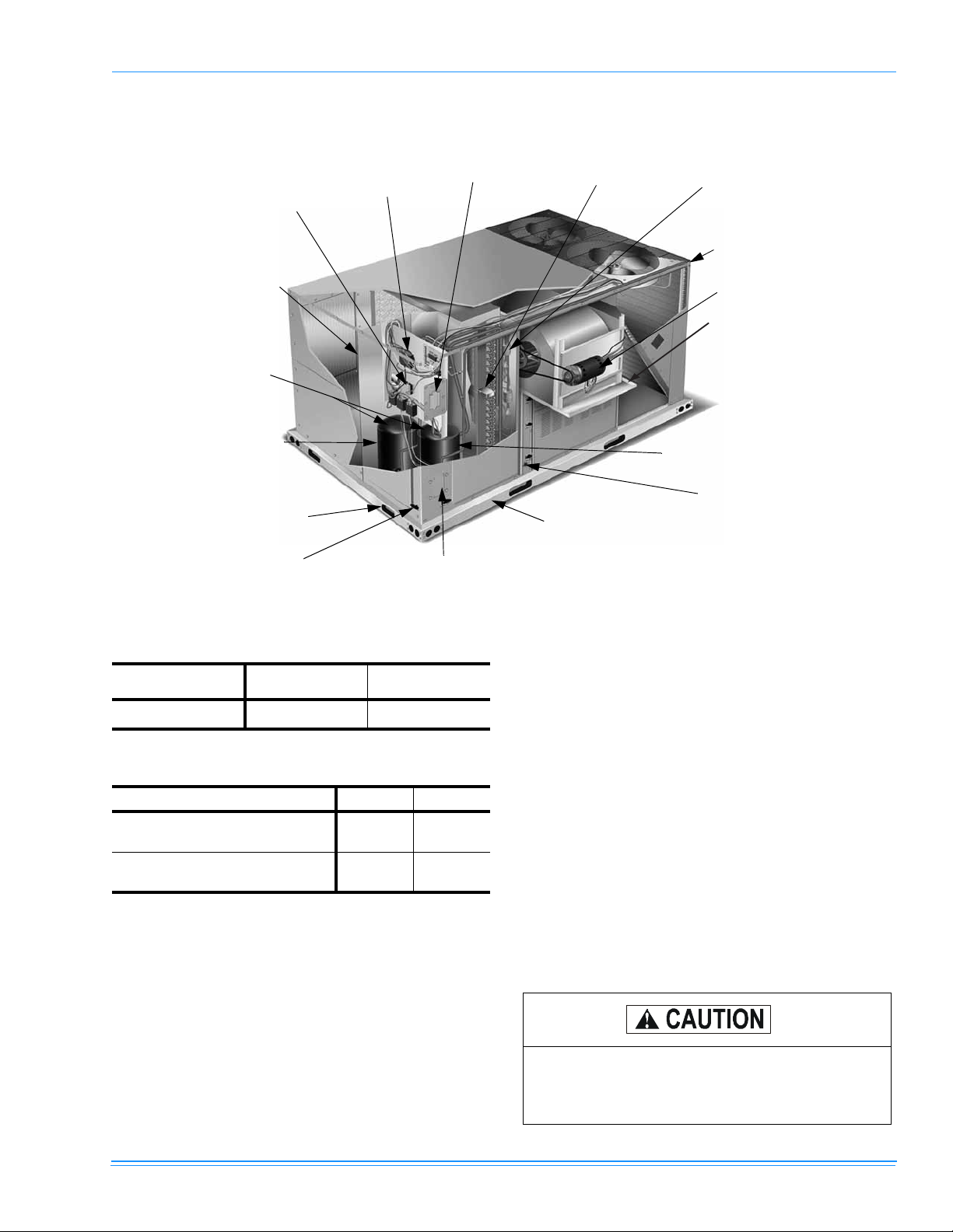
Terminal block for
hi-voltage connection
Simplicity™ Control board
w/screw connector
for T-stat wiring and
network connection
Disconnect location
(optional disconnect switch)
Filter access (2” throw-away)
Filter drier (solid
core)
Second model nameplate inside hinged
access panel
Dual stage
cooling for
max. comfort
Compressor #2
access (highefficiency compressor with
crankcase heater
Base rails w/forklift slots (3 sides)
and lifting holes)
Tool-less door
latch
Side entry power
and control wiring
knockouts
FIGURE 4 - PREDATOR® COMPONENT LOCATION
TABLE 1: UNIT VOLTAGE LIMITATIONS
Power Rating Minimum Maximum
380 350 418
TABLE 2: UNIT TEMPERATURE LIMITATIONS
Temperature Min. Max.
Wet Bulb Temperature (°F) of Air on
Evaporator Coil
Dry Bulb Temperature (°F) of Air on
Condenser Coil
*.
A low ambient accessory is available for operation
57 72
*
0
125
down to -20°F.
LOCATION
Use the following guidelines to select a suitable location for
these units:
1. Unit is designed for outdoor installation only.
2. Condenser coils must have an unlimited supply of air.
Where a choice of location is possible, position the unit
on either north or east side of building.
3. Suitable for mounting on roof curb.
Condenser
section
Belt-drive
blower motor
Slideout motor
& blower
assembly for
easy access
adjustment &
service
Compressor #1 access (highefficiency compressor w/
crankcase heater))
Slide-out drain pan
with steel 3/4” FPT
Roof curbs in eight- and fourteen-inch
heights. Roof curbs for transitioning from
York Sunline™ footprint to the DM
Series footprint are also available
(field-installed accessory)
connection
4. For ground level installation, use a level concrete slab
with a minimum thickness of 4 inches. The length and
width should be at least 6 inches greater than the unit
base rails. Do not tie slab to the building foundation.
5. Roof structures must be able to support the weight of the
unit and its options/accessories. Unit must be installed
on a solid, level roof curb or appropriate angle iron
frame.
6. Maintain level tolerance to 1/2” across the entire width
and length of unit.
RIGGING AND HANDLING
Exercise care when moving the unit. Do not remove any
packaging until the unit is near the place of installation. Rig
the unit by attaching chain or cable slings to the lifting holes
provided in the base rails. Spreader bars, whose length
exceeds the largest dimension across the unit, MUST be
used across the top of the unit.
If a unit is to be installed on a roof curb other than a
YORK roof curb, gasketing must be applied to all
surfaces that come in contact with the unit underside.
Unitary Products Group 11
Before lifting, make sure the unit weight is distributed equally on the rigging cables so it will lift evenly.
Units may be moved or lifted with a forklift. Slotted openings
in the base rails are provided for this purpose.
035-17311-003-A-0704
TABLE 4: 6 POINT LOAD WEIGHT
Model
ABCDEF
DM090
DM120
DM150
*.
Weights include largest gas heat option.
158 142 128 187 207 230
168 151 136 198 219 244
180 161 145 212 235 262
Location (lbs.)
*
LENGTH OF FORKS MUST BE A MINIMUM OF 60
INCHES.
All panels must be secured in place when the unit is
lifted.
The condenser coils should be protected from rigging cable damage with plywood or other suitable
material.
L E F T
A
F R O N T
CB
TABLE 5: 4 POINT LOAD WEIGHT
Model
ABCD
DM090
DM120
DM150
*.
Weights include largest gas heat option.
L E F T
A
230 197 287 336
245 209 305 357
262 224 327 382
B
Location (lbs.)
C
F
FIGURE 6 - UNIT 6 POINT LOAD
*
F R O N T
D
E
D
FIGURE 5 - UNIT 4 POINT LOAD
TABLE 3: UNIT WEIGHTS
Model
DM090
DM120
DM150
Econ. 85 84
w/ PE 150 148
Elec. Heat
*.
†.
Shipping Weight
2
Weights include largest gas heat option.
54kW heater.
*
(lb.)
Operating Weight
1056 1051
112 1 1116
1200 1195
49 49
†
(lb.)
FIGURE 7 - UNIT CENTER OF GRAVITY
CLEARANCES
All units require particular clearances for proper operation
and service. Installer must make provisions for adequate
ventilation air in accordance with applicable provisions of the
local building codes. Refer to Table 6 for clearances required
for combustible construction, servicing, and proper unit operation.
47-1/2"
LEFT
12 Unitary Products Group
25-1/2"
FRONT
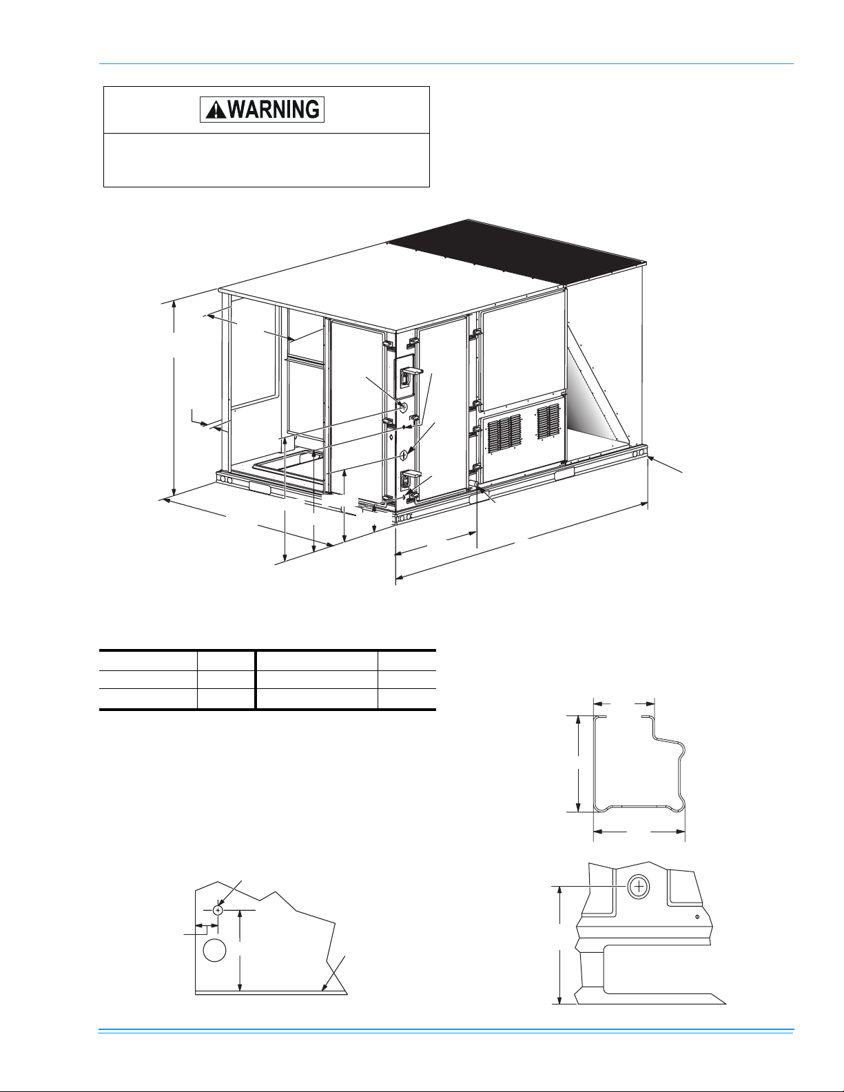
035-17311-003-A-0704
A
DETAIL B
Do not permit overhanging structures or shrubs to
obstruct condenser air discharge outlet, combustion
air inlet or vent outlets.
3 0 - 1 1 / 3 2
5 0 - 3 / 4
P o w e r
E n t r y
Ø 2 - 1 / 2
C o n t r o l
E n t r y
Ø 7 / 8
4 - 1 / 4
3 0 - 3 / 1 6
5 9
L E F T
2 4 - 3 / 1 6
FIGURE 8 - UNIT DIMENSIONS
TABLE 6: UNIT CLEARANCES
*
Top
Front
†
Rear
*.
Units must be installed outdoors. Overhanging structure or shrubs should not obstruct condenser air discharge outlet.
†.
To remove the slide-out drain pan, a rear clearance of
sixty inches is required. If space is unavailable, the
drain pan can be removed through the front by separating the corner wall.
‡.
Units may be installed on combustible floors made from
wood or class A, B or C roof covering materials.
DETAIL A
72”
36”
36”
Bottom
G a s P i p e I n l e t
Right
Left
1 7 - 3 / 1 6
‡
6 - 3 / 1 6
12”
36”
0”
P o w e r
E n t r y
Ø 2 - 1 / 2
C o n v e n i e n c e
P o w e r
O u t l e t
E n t r y
Ø 7 / 8
2 7
F o r D r a i n
D i m e n s i o n s
S e e D e t a i l B
8 9
F R O N T
F o r B a s e r a i l
D i m e n s i o n s
S e e D e t a i l
NOTE: A one-inch clearance must be provided between
any combustible material and the supply ductwork
for a distance of 3 feet from the unit.
2 - 3 / 8
3 - 3 / 4
3 - 9 / 1 6
DETAIL C
5 - 1 / 4
1 7 - 1 3 / 1 6
V i e w o f W a l l A c r o s s f r o m C o i l
B a s e
P a n
5 - 3 / 8
Unitary Products Group 13
035-17311-003-A-0704
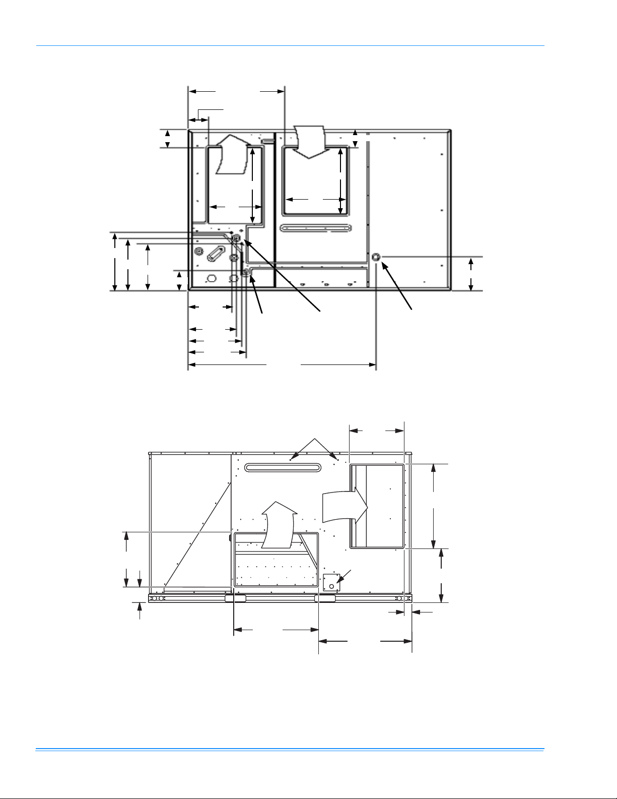
6
.
32-11/16
6-13/16
6-13/16
Return
Air
18
27-1/2
Bottom
Condensate
Entry
FRONT
63-1/2
21-3/16
19-3/16
17-3/16
LEFT
7-1/8
14-
23/32
16-3/8
18-1/16
19-5/8
FIGURE 9 - BOTTOM DUCT OPENINGS (FROM ABOVE)
Supply
Air
21
Bottom
Power, Control
Convenience
Outlet Wiring
Entries
and
24
6-13/16
Bottom Gas
Supply Entry
12-15/1
1 8 - 1 / 4
5 - 5 / 3 2
FIGURE 10 - REAR DUCT DIMENSIONS
2 8 - 1 / 4
S u p p l y
A i r
D o t P l u g s
R e t u r n
A i r
1 8 - 1 / 4
P a t c h P l a t e
F o r S l i d e - O u t
D r a i n P a n
2 - 3 1 / 3 2
3 1 - 1 1 / 1 6
2 8 - 1 / 4
1 8 - 1 / 1 6
14 Unitary Products Group
 Loading...