

Page 1
®
INSTALLATION MANUAL
SINGLE PACKAGE
HEAT PUMP / ELECTRIC HEAT
MODELS: PHE6 SERIES
3 – 5 TONS (3 PHASE)
LIST OF SECTIONS
GENERAL INFORMATION . . . . . . . . . . . . . . . . . . . . . . . . . . . . . . . . 1
SAFETY . . . . . . . . . . . . . . . . . . . . . . . . . . . . . . . . . . . . . . . . . . . . . . . 1
MODEL NUMBER NOMENCLATURE . . . . . . . . . . . . . . . . . . . . . . . 2
INSTALLATION . . . . . . . . . . . . . . . . . . . . . . . . . . . . . . . . . . . . . . . . . 2
AIRFLOW PERFORMANCE . . . . . . . . . . . . . . . . . . . . . . . . . . . . . . 12
LIST OF FIGURES
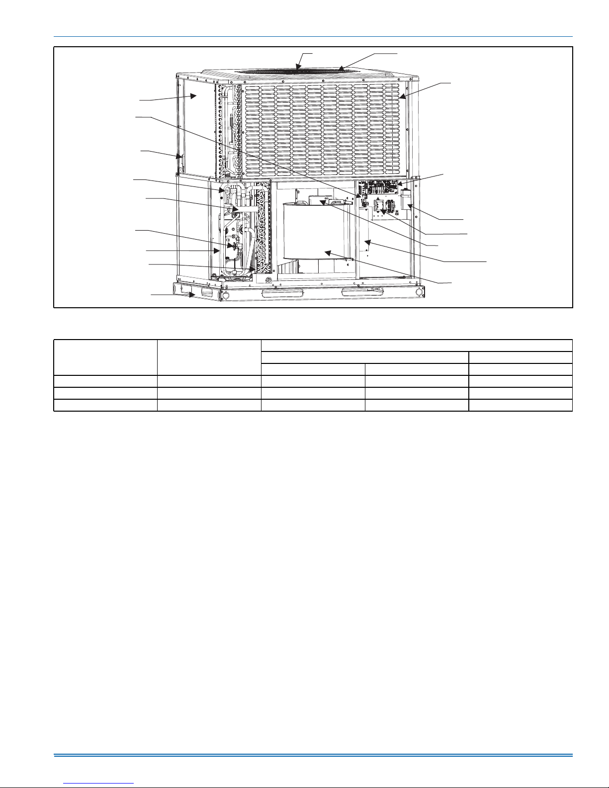
Component Location . . . . . . . . . . . . . . . . . . . . . . . . . . . . . . . . . . . . . 3
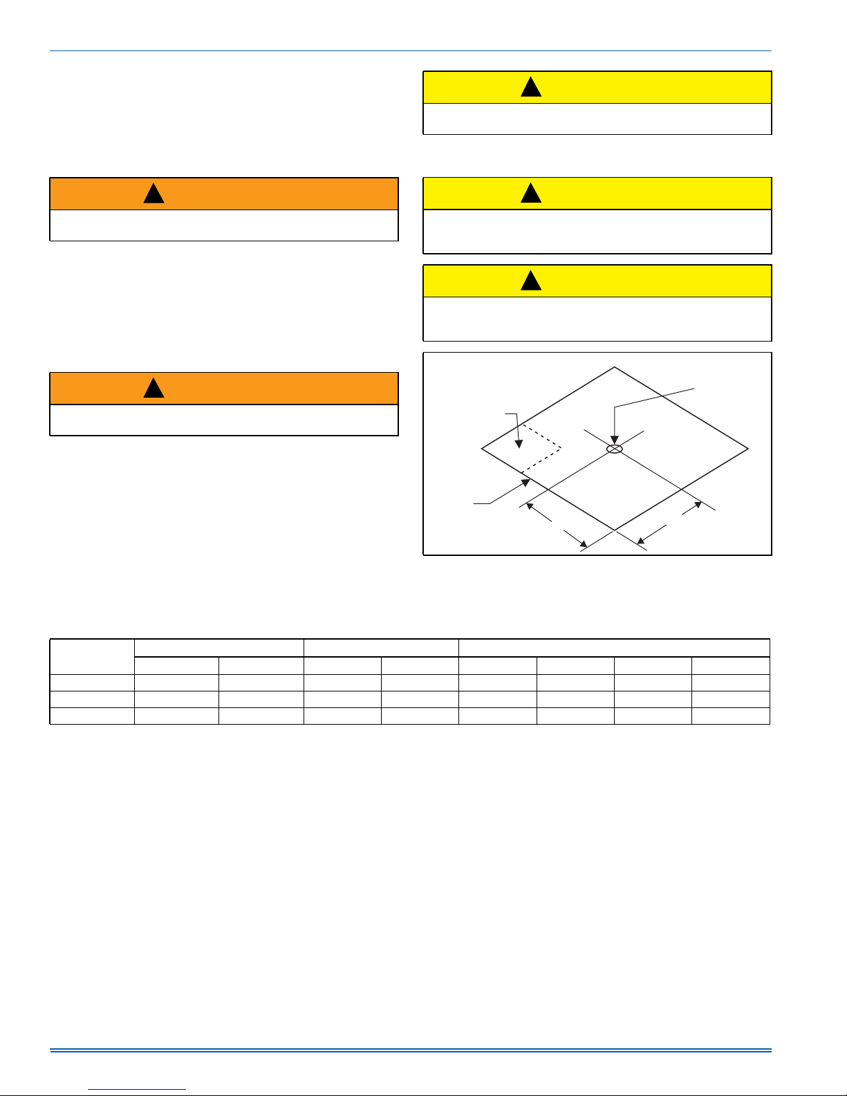
Unit 4 Point Load Weight . . . . . . . . . . . . . . . . . . . . . . . . . . . . . . . . . . 4
Unit Dimensions . . . . . . . . . . . . . . . . . . . . . . . . . . . . . . . . . . . . . . . . . 5
Bottom Duct Dimensions (inches) . . . . . . . . . . . . . . . . . . . . . . . . . . . 6
Rear Duct Dimensions (inches) . . . . . . . . . . . . . . . . . . . . . . . . . . . . . 6
Typical Field Control Wiring Diagram For Heat Pump Models . . . . . . 7
Typical Field Power Wiring Diagram . . . . . . . . . . . . . . . . . . . . . . . . . 7
LIST OF TABLES
Unit Limitations . . . . . . . . . . . . . . . . . . . . . . . . . . . . . . . . . . . . . . . . . . 3
Weights and Dimensions . . . . . . . . . . . . . . . . . . . . . . . . . . . . . . . . . . 4
Unit Dimensions . . . . . . . . . . . . . . . . . . . . . . . . . . . . . . . . . . . . . . . . . 5
Unit Clearances . . . . . . . . . . . . . . . . . . . . . . . . . . . . . . . . . . . . . . . . . 5
Electrical Data - 208-3-60 - Single Source Power . . . . . . . . . . . . . . . 8
Electrical Data For 208-3-60 Multi Source Power . . . . . . . . . . . . . . . 8
Electrical Data - 230-3-60 Single Source Power . . . . . . . . . . . . . . . . 9
Electrical Data For 230-3-60 Multi Source Power . . . . . . . . . . . . . . . 9
Single-point Wiring Kit Part Numbers . . . . . . . . . . . . . . . . . . . . . . . . 10
Physical Data . . . . . . . . . . . . . . . . . . . . . . . . . . . . . . . . . . . . . . . . . . 10
Airflow Performance - Side Duct Application . . . . . . . . . . . . . . . . . . 12
®
OPERATION . . . . . . . . . . . . . . . . . . . . . . . . . . . . . . . . . . . . . . . . . .13
MAINTENANCE . . . . . . . . . . . . . . . . . . . . . . . . . . . . . . . . . . . . . . . .18
TYPICAL WIRING DIAGRAMS . . . . . . . . . . . . . . . . . . . . . . . . . . . . 19
START UP SHEET . . . . . . . . . . . . . . . . . . . . . . . . . . . . . . . . . . . . . . 23
Demand Defrost Control . . . . . . . . . . . . . . . . . . . . . . . . . . . . . . . . . .15
Blower Control . . . . . . . . . . . . . . . . . . . . . . . . . . . . . . . . . . . . . . . . .16
Measuring External Static Pressure . . . . . . . . . . . . . . . . . . . . . . . . .17
Connection Wiring Diagram . . . . . . . . . . . . . . . . . . . . . . . . . . . . . . .19
Ladder Wiring Diagram . . . . . . . . . . . . . . . . . . . . . . . . . . . . . . . . . . .20
R-410A Quick Reference Guide . . . . . . . . . . . . . . . . . . . . . . . . . . . .21
Electric Heat Multipliers . . . . . . . . . . . . . . . . . . . . . . . . . . . . . . . . . .13
Recommended Blower Speed for Electric Heat . . . . . . . . . . . . . . . .13
Electric Heat Blower Off Delay . . . . . . . . . . . . . . . . . . . . . . . . . . . . .13
Additional Static Resistance . . . . . . . . . . . . . . . . . . . . . . . . . . . . . . .13
Indoor Blower Control Fault Codes . . . . . . . . . . . . . . . . . . . . . . . . . .14
Delay Profile Descriptions . . . . . . . . . . . . . . . . . . . . . . . . . . . . . . . .14
Demand Defrost Selection . . . . . . . . . . . . . . . . . . . . . . . . . . . . . . . .15
Test Pins . . . . . . . . . . . . . . . . . . . . . . . . . . . . . . . . . . . . . . . . . . . . . .16
Demand Defrost Fault Codes . . . . . . . . . . . . . . . . . . . . . . . . . . . . . .16
Thermostat Signals . . . . . . . . . . . . . . . . . . . . . . . . . . . . . . . . . . . . . .17
SECTION I: GENERAL INFORMATION
PHE units are factory assembled heat pumps designed for outdoor
installation on a roof top or a slab. Field-installed optional electric heater
accessories are available to provide supplemental electric heat combined with electric cooling and heating.
The units are completely assembled on rigid, removable base rails. All
piping, refrigerant charge, and electrical wiring is factory installed and
tested. The units require only electric power condensate drain and duct
connections at the point of installation.
SECTION II: SAFETY
This is a safety alert symbol. When you see this symbol on
labels or in manuals, be alert to the potential for personal
injury.
Understand and pay particular attention to the signal words DANGER,
WARNING, or CAUTION.
DANGER indicates an imminently hazardous situation, which, if not
avoided, will result in death or serious injury.
Johnson Controls Unitary Products 5285477-UIM-A-1016
WARNING indicates a potentially hazardous situation, which, if not
avoided, could result in death or serious injury.
CAUTION indicates a potentially hazardous situation, which, if not
avoided may result in minor or moderate injury. It is also used to
alert against unsafe practices and hazards involving only property damage.
!
WARNING
Improper installation may create a condition where the operation of
the product could cause personal injury or property damage.
Improper installation, adjustment, alteration, service or maintenance
can cause injury or property damage. Failure to carefully read and
follow all instructions in this manual can result in furnace malfunction, death, personal injury and/or property damage. Only a
qualified contractor, installer or service agency should install this
product.
Page 2
5285477-UIM-A-1016
!
CAUTION
This product must be installed in strict compliance with the installation instructions and any applicable local, state, and national codes
including, but not limited to building, electrical, and mechanical
codes.
!
WARNING
Before performing service or maintenance operations on unit, turn off
main power switch to unit. Electrical shock could cause personal
injury. Improper installation, adjustment, alteration, service or maintenance can cause injury or property damage. Refer to this manual.
For assistance or additional information consult a qualified installer,
service agency or the gas supplier.
!
CAUTION
This system uses R-410A refrigerant which operates at higher pressures than R-22. No other refrigerant may be used in this system.
Gage sets, hoses, refrigerant containers and recovery systems must
be designed to handle R-410A. If you are unsure, consult the equipment manufacturer. Failure to use R-410A compatible servicing
equipment may result in property damage or injury.
Due to system pressure, moving parts, and electrical components,
installation and servicing of air conditioning equipment can be hazardous. Only qualified, licensed service personnel should install, repair, or
service this equipment. Unlicensed personnel can perform basic maintenance functions of cleaning coils and filters and replacing filters.
Observe all precautions in the literature, labels, and tags accompanying
the equipment whenever working on air conditioning equipment. Be
sure to follow all other applicable safety precautions and codes including.
Wear safety glasses and work gloves. Use quenching cloth and have a
fire extinguisher available during brazing operations.
INSPECTION
As soon as a unit is received, it should be inspected for possible damage during transit. If damage is evident, the extent of the damage
should be noted on the carrier’s freight bill. A separate request for
inspection by the carrier’s agent should be made in writing.
REPLACEMENT PARTS
Contact your local Unitary Products parts distribution center for authorized replacement parts.
SECTION III: MODEL NUMBER NOMENCLATURE
PHE 4 A 24 2 1 A
1234689
1. Model Family
PHE - packaged heat pump with electric heat
PCG - packaged A/C with gas heat,
PHG - packaged heat pump with gas heat,
PCE - packaged A/C with electric heat,
2. Nominal Cooling Efficiency
4 = 14 SEER, 6 = 16 SEER, etc.
3. Cabinet Size
A = small 35 x 51, B = large 45 x 51
4. Nominal Air Conditioning Cooling Capacity BTUx1000
24 = 24,000 BTU, etc.
Examples:
PHE6B4221A is a packaged heat pump, 16 SEER, 3-1/2 ton, large cabinet, 230 volt, single phase model, (first generation, first release).
5. Gas Heating Input BTU/Hr x 1000
050 = 50,000 BTU/Hr. input, blank = electric heat
6. Voltage-Phase-Frequency
2 = 208/230-1-60, 3=208/230-3-60, 4 = 460-3-60
7. NOx Approval
X = low-NOx, blank = not low-Nox
8. Generation Level
1 = first generation
9. Revision Level
A = original release, B = second release
SECTION IV: INSTALLATION
LIMITATIONS
These units must be installed in accordance with the following national
and local safety codes.
1. National Electrical Code ANSI/NFPS No. 70 or Canadian Electrical
Code Part 1, C22.1 (latest editions).
2. Local plumbing and waste water codes and other applicable local
codes.
2 Johnson Controls Unitary Products
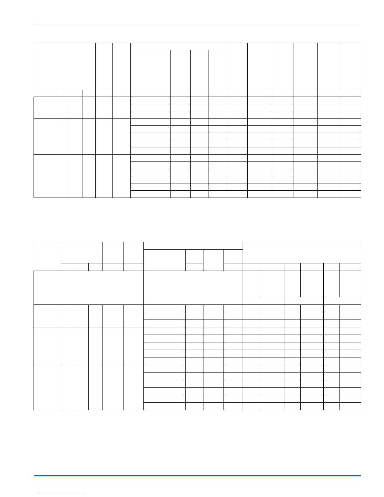
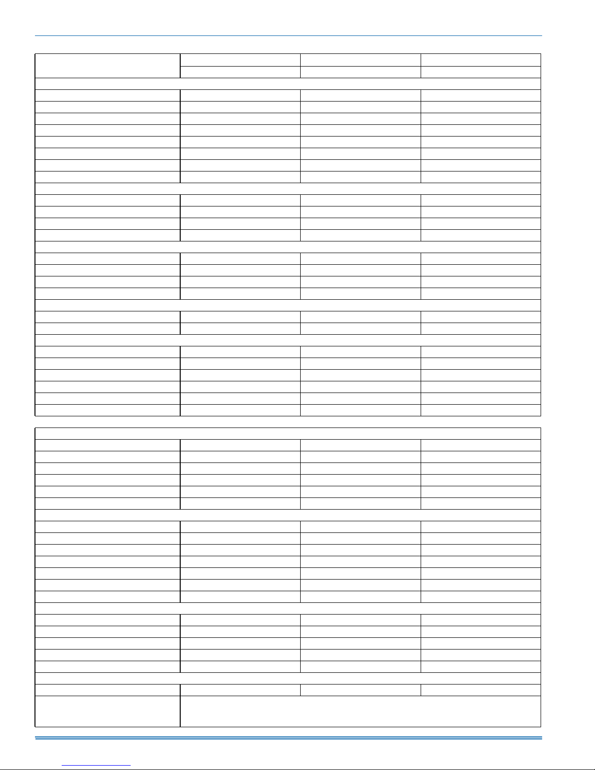
Refer to Tables 2-3 for unit weight & dimensions, Tables 5-9 for electrical data and Table 10 for physical data.
If components are to be added to a unit to meet local codes, they are to
be installed at the dealer's and/or the customer's expense.
Size of unit for proposed installation should be based on heat loss/heat
gain calculations made in accordance with industry recognized procedures such as the Air Conditioning Contractors of America (manual J).
Page 3
5285477-UIM-A-1016
OUTDOOR COIL
ECM BLOWER MOTOR
CONTROL BOARD
AMBIENT
TEMPERATURE
SENSOR
OUTDOOR TXV
REVERSING
VALV E
INDOOR TXV
COMPRESSOR
INDOOR COIL
REMOVABLE
BASE RAILS
FIGURE 1: Component Location
Table 1: Unit Limitations
Model Unit Voltage
B36 208/230-3-60 187 252 125
B48 208/230-3-60 187 252 125
B60 208/230-3-60 187 252 125
FAN MOTOR
OUTDOOR FAN
BLOWER MOTOR
COIL GUARD PANEL
DEFROST CONTROL BOARD
CAPACITOR
TRANSFORMER
OPTIONAL
ELECTRIC HEAT KIT
INDOOR BLOWER
Unit Limitations
Applied Voltage Outdoor DB Temp
Min Max Max (°F)
A0588-001
Johnson Controls Unitary Products 3
Page 4
5285477-UIM-A-1016
LOCATION
Use the following guidelines to select a suitable location for these units:
1. Unit is designed for
2. Outdoor coils must have an unlimited supply of air. Where a choice
of location is possible, position the unit on either north or east side
of building.
3. Suitable for mounting on roof curb.
outdoor installation only.
!
CAUTION
Before lifting, make sure the unit weight is distributed equally on the
rigging cables so it will lift evenly.
Units may be moved or lifted with a forklift. Slotted openings in the base
rails are provided for this purpose.
!
WARNING
Do not attach supply and return duct work to the bottom of the unit
base pan as the drain pan could be compromised.
4. For ground level installation, a level pad or slab should be used.
The thickness and size of the pad or slab used should meet local
codes and support unit weight. Do not tie the slab to the building
foundation.
5. Roof structures must be able to support the weight of the unit and
its options/accessories. Unit must be installed on a solid, level roof
curb or appropriate angle iron frame.
6. Maintain level tolerance to 1/8” across the entire width and length of
unit.
!
WARNING
Do not permit overhanging structures or shrubs to obstruct outdoor
air discharge outlet.
CLEARANCES
All units require certain clearances for proper operation and service.
Refer to Table 4 for the clearances required for construction, servicing
and proper unit operation.
RIGGING AND HANDLING
Exercise care when moving the unit. Do not remove any packaging until
the unit is near the place of installation. Rig the unit by attaching chain
or cable slings to the lifting holes provided in the base rails. Spreader
bars, whose length exceeds the largest dimension across the unit,
MUST be used across the top of the unit.
!
CAUTION
If a unit is to be installed on a roof curb other than a Unitary Products
roof curb, gasket or sealant must be applied to all surfaces that come
in contact with the unit underside.
!
CAUTION
All panels must be secured in place when the unit is lifted.
The outdoor coils should be protected from rigging cable damage
with plywood or other suitable material.
"D"
CENTER OF
COMPRESSOR
"A"
FRONT
OF UNIT
X
FIGURE 2: Unit 4 Point Load Weight
"B"
GRAVITY
Y
A0295-001
"C"
Table 2: Weights and Dimensions
Model Weight (lbs.) Center of Gravity 4 Point Load Location (lbs.)
Shipping Operating X Y ABCD
PHE6B36 453 448 29 15 158 108 101 86
PHE6B48 501 496 29 15 168 130 119 84
PHE6B60 528 523 30 15 177 136 128 87
4 Johnson Controls Unitary Products
Page 5
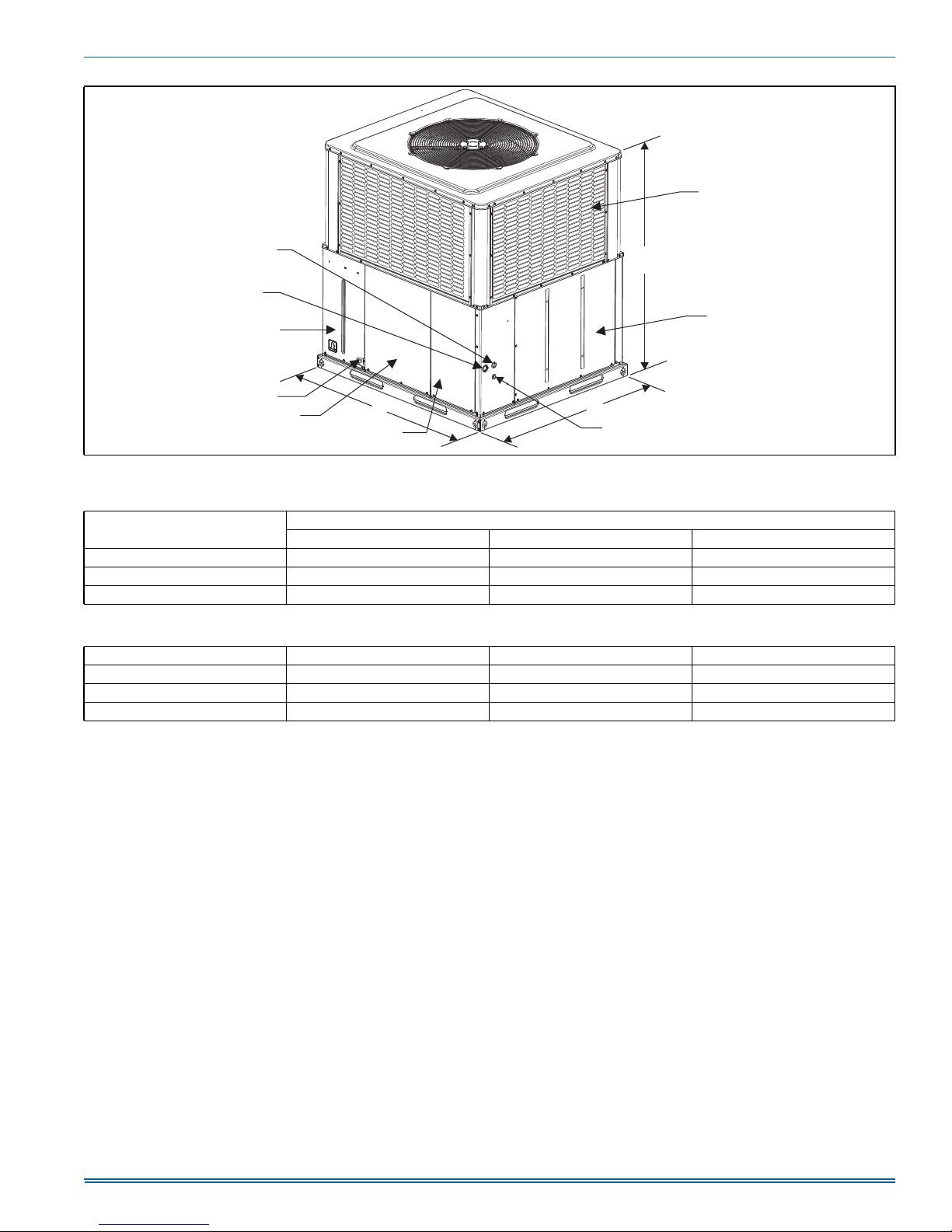
HIGH VOLTAGE
CONNECTION 7/8”
HIGH VOLTAGE
CONNECTION 1-3/32”
COMPRESSOR
ACCESS PANEL
5285477-UIM-A-1016
COIL GUARD
C
HEAT SECTION
ACCESS PANEL
CONDENSATE
DRAIN
BLOWER
ACCESS
PANEL
A
CONTROL / HEAT
ACCESS PANEL
B
LOW VOLTAGE CONNECTION
A0379-001
FIGURE 3: Unit Dimensions
Table 3: Unit Dimensions
Model
ABC
Dimensions (inches)
B36 51-1/4 45-3/4 49
B48 51-1/4 45-3/4 53
B60 51-1/4 45-3/4 55
Table 4: Unit Clearances
Direction Distance (inches) Direction Distance (inches)
1
Top
36 Right Side 36
Side Opposite Ducts 36 Left Side 24
Duct Panel 0 Bottom 2
1. Minimum Clearance of 1inch all sides of supply air duct for the first 3 foot of duct for 20 & 25 kW., zero inches there after. For all other heaters, zero inch clearance
all sides for entire length of duct.
2. Units must be installed outdoors. Over hanging structure or shrubs should not obscure outdoor air discharge outlet.
3. Units may be installed on combustible floors made from wood or class A, B or C roof covering materials.
NOTE: For units applied with a roof curb, the minimum clearance may be reduced from 1 inch to 1/2 inch? between combustible roof curb material and this supply
air duct.
3
1
Johnson Controls Unitary Products 5
Page 6
5285477-UIM-A-1016
D
C
A
B
A
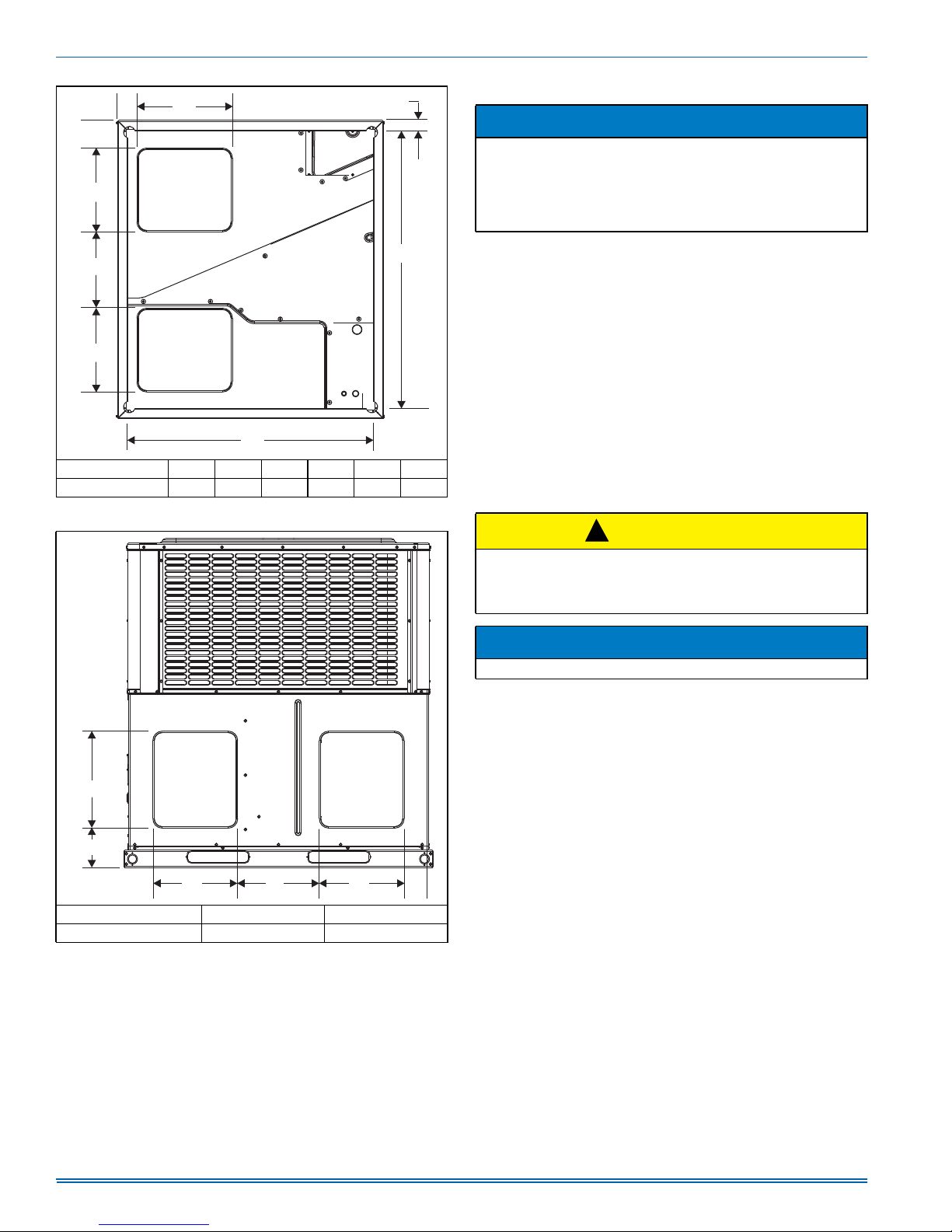
Model A B C D E F
36, 48, 60 14 13.5 5 3.5 47.5 42
FIGURE 4: Bottom Duct Dimensions (inches)
16
RETURN
AIR DUCT
SUPPLY
AIR DUCT
VIEW LOOKING UP
AT BOTTOM OF UNIT
F
1.75
E
A0343-001
DUCTWORK
NOTICE
All units are shipped in the horizontal supply/return configuration. It is
important to reduce the possibility of any air leakage through the bottom duct covers (resulting from cut, torn, or rolled gasket) due to
improper handling or shipping processes. To ensure a good tight
seal, it is recommended that silicone caulk and/or foil tape be applied
along the cover edges.
These units are adaptable to downflow use as well as rear supply and
return air duct openings. To convert to downflow, use the following
steps:
1. Remove the duct covers found in the bottom return and supply air
duct openings. There are four (4) screws securing each duct cover
(save these screws to use in Step 2).
2. Install the duct covers (removed in step one) to the rear supply and
return air duct openings. Secure with the screws used in step one.
3. Seal duct covers with silicone caulk.
Duct work should be designed and sized according to the methods of
the Air Conditioning Contractors of America (ACCA), as set forth in their
Manual D.
A closed return duct system shall be used. This shall not preclude use
of economizers or ventilation air intake. Flexible duct connectors are
recommended in the supply and return duct work to minimize the transmission of vibration and noise.
!
CAUTION
When fastening duct work to the side duct flanges on the unit, insert
the screws through the duct flanges only. DO NOT insert the screws
through the casing. Outdoor duct work must be insulated and waterproofed.
SUPPLY
15.6
6.75
A0344-001
Model A B
36, 48, 60 13.6 14
FIGURE 5: Rear Duct Dimensions (inches)
AIR DUCT
A
B
RETURN
AIR DUCT
A
4.3
NOTICE
Be sure to note supply and return openings.
Refer to Figures 4 and 5 for information concerning rear and bottom
supply and return air duct openings.
FILTERS
Proper filter size is very important. Filter size, type and pressure drop
should always be considered during duct system design.
All 3 phase units include a filter frame kit which is shipped inside the
unit from production. Field installation is required.
A filter rack and high velocity filters are standard on three phase units.
Filters must always be used and must be kept clean. When filters
become dirt laden, insufficient air will be delivered by the blower,
decreasing your units efficiency and increasing operating costs and
wear-and-tear on the unit and controls.
Filters should be checked monthly; this is especially important since this
unit is used for both heating and cooling.
6 Johnson Controls Unitary Products
Page 7
5285477-UIM-A-1016
p
CONDENSATE DRAIN
A condensate trap must be installed in the condensate drain. The
plumbing must conform to local codes.
Use Teflon tape or pipe thread compound if needed.
!
CAUTION
Hand tighten only.
SERVICE ACCESS
Access to all serviceable components is provided at the following locations:
• Coil guards
• Unit top panel
• Corner posts
• Blower access panel
• Control access panel
• Indoor coil access panel
• Compressor access panel
• Heat section access panel
Refer to Figure 3 for location of these access locations and minimum
clearances in Table 4.
!
CAUTION
This system uses R-410A refrigerant which operates at higher pressures than R-22. No other refrigerant may be used in this system.
Gauge sets, hoses, refrigerant containers and recovery systems
must be designed to handle R-410A. If you are unsure, consult the
equipment manufacturer. Failure to use R-410A compatible servicing
equipment may result in property damage or injury.
!
WARNING
Wear safety glasses and gloves when handling refrigerants. Failure
to follow this warning can cause serious personal injury.
Refer to Figure 13 for the R-410A Quick Reference Guide.
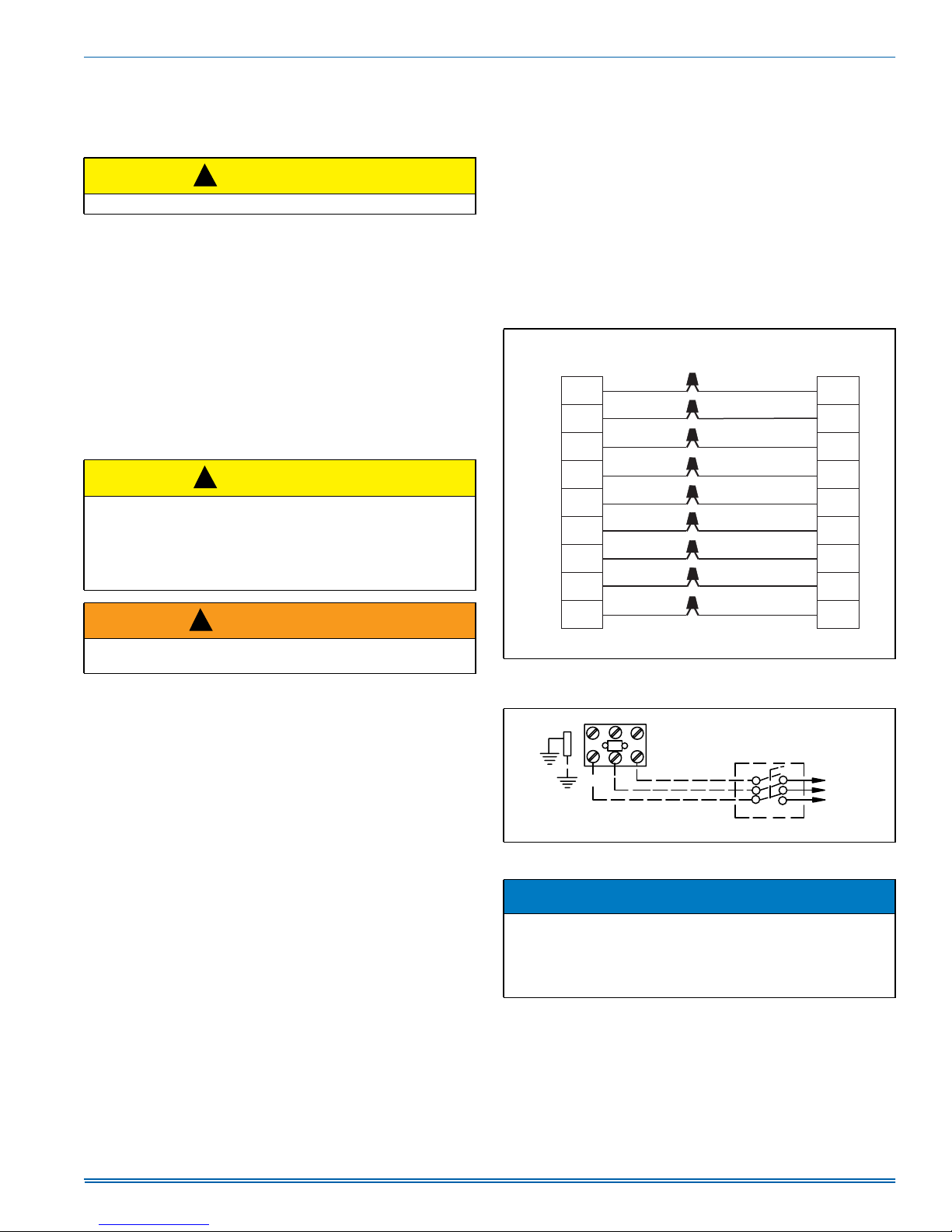
THERMOSTAT
The room thermostat should be located on an inside wall approximately
60" above the floor where it will not be subject to drafts, sun exposure
or heat from electrical fixtures or appliances. Sealant should be used
behind thermostat to prevent air infiltration. Follow manufacturer's
instructions enclosed with the thermostat for general installation procedure. Color coded insulated wires (minimum #18 AWG) should be used
to connect thermostat to unit. See Figure 6.
If a field supplied electric heat kit is installed, this unit requires the use
of a 3 heat / 2 cool (3H/2C) heat pump thermostat for proper operation.
For units installed with 6HK heat kits of 18 kW and larger, a 4H/2C heat
pump thermostat should be used. Do not use power stealing thermostats.
POWER AND CONTROL WIRING
Field wiring to the unit must conform to provisions of the current N.E.C.
ANSI/NFPA No. 70 or C.E.C. and/or local ordinances. The unit must be
electrically grounded in accordance with local codes or, in their
absence, with the N.E.C./C.E.C. Voltage tolerances which must be
maintained at the compressor terminals during starting and running
conditions are indicated on the unit Rating Plate and Table 1.
The wiring entering the cabinet must be provided with mechanical
strain relief.
A fused disconnect switch should be field provided for the unit. If any of
the wire supplied with the unit must be replaced, replacement wire must
be of the type shown on the wiring diagram.
Electrical service must be sized properly to carry the load. Each unit
must be wired with a separate branch circuit fed directly from the main
distribution panel and properly fused.
Refer to Figures 6 and 7 for typical field wiring and to the appropriate
unit wiring diagram for control circuit and power wiring information.
Unit comes wired for 230 volt power. If supply power is 208 volt, wires
connected to the control transformer 230V tap must be moved to the
208V tap.
Minimum wire size of 18 AWG wire should be used for all eld
installed control wiring.
THERMOSTAT
C
R
O
YorY1
Y2
G
W2
W1
HUM
NOTE:
Heat Antici
FIGURE 6: Typical Field Control Wiring Diagram For Heat Pump
FIGURE 7: Typical Field Power Wiring Diagram
ator should be set at 0.35 AMPS for all models.
Models
&217$&725
*5281'
/8*
5()(572(/(&75,&$/
'$7$7$%/(6726,=(
7+(',6&211(&7
YELLOW/BLACK
WHITE/BLACK
),(/'6833/,('
CONTROL HARNESS
BLUE
RED
ORANGE
YELLOW
GREEN
WHITE
GRAY
',6&211(&7
C
R
O
Y1
Y2
G
W2
W1
HUM
7+5((
3+$6(
32:(5
6833<
$
A0560-001
NOTICE
In some horizontal applications, the service disconnects on the electric heat kits must be rotated 180° so the up position of the disconnect is the ON position. This service disconnect orientation change is
required by UL1995, Article 26.19 (in reference to all circuit breakers).
Johnson Controls Unitary Products 7
Page 8
5285477-UIM-A-1016
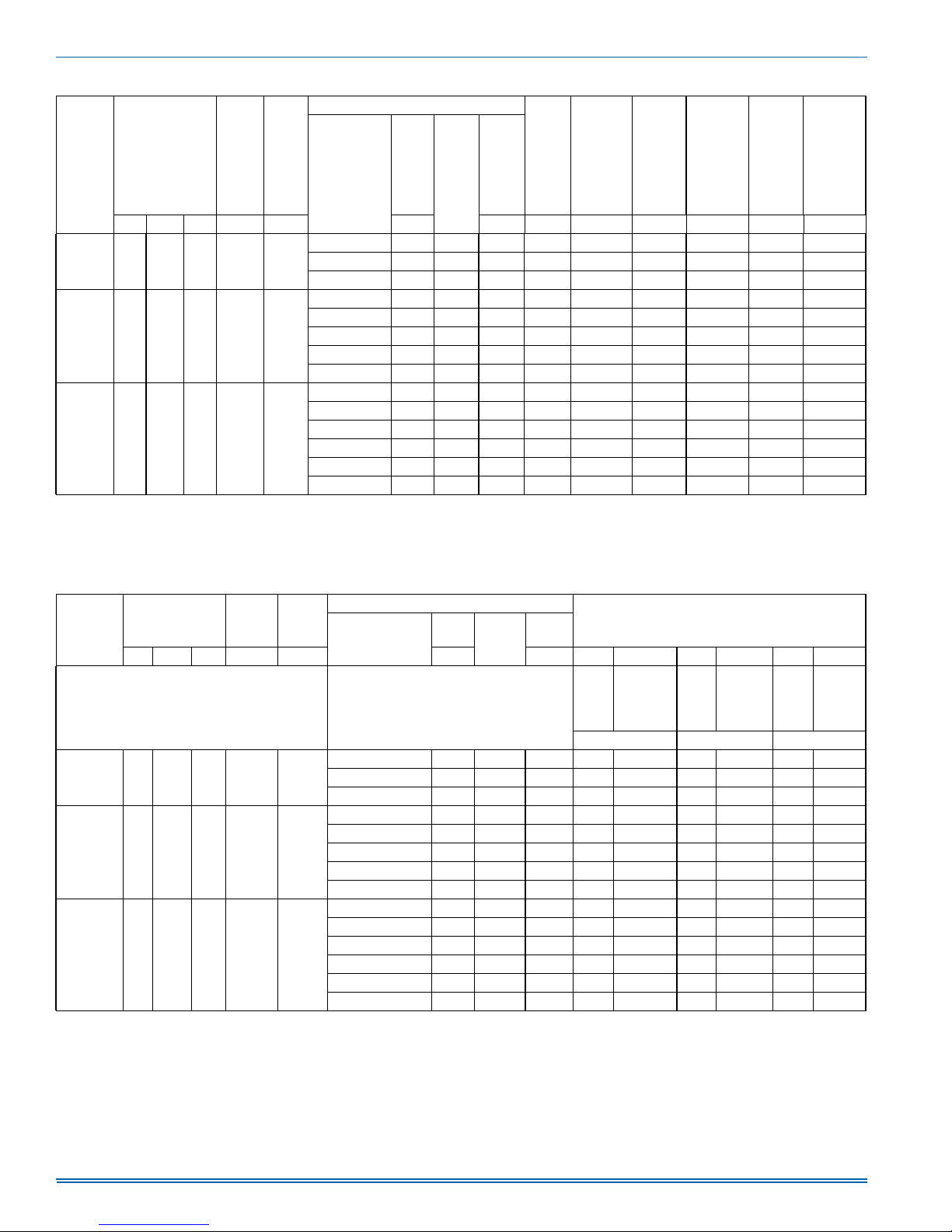
Table 5: Electrical Data - 208-3-60 - Single Source Power
Model
Compressor
OD Fan
Motor
Blower
Motor
Electric Heat Option
Heater Kit
Heater
kW
Stages
Heater
Amps
MCA
(Total
Unit)
1
Fuse
Max
2
or
Breaker
3
Size
(Total
MCA
(Unit
Less
Heater)
Unit)
RLA LRA MCC FLA FLA 208 208 208 208 208 208 208 208
none -- -- -- 20.0 30 20.0 30 - -
PHE6B36 11.6 73.0 18.1 1.7 3.8
6HK06501025 7.2 1 20.0 45.0 50 20.0 30 25.0 25
6HK06501525 10.8 1 30.0 57.5 60 20.0 30 37.5 40
none -- -- -- 24.6 35 24.6 35 - -
6HK06501025 7.2 1 20.0 49.6 50 24.6 35 25.0 25
PHE6B48 14.0 83.1 21.9 1.7 5.4
6HK06501525 10.8 1 30.0 62.1 70 24.6 35 37.5 40
6HK06501825 13.0 1 36.1 69.7 70 24.6 35 45.1 50
6HK16502025 14.4 2 40.0 74.6 80 24.6 35 50.0 *
none -- -- -- 29.0 45 29.0 45 - -
6HK06501025 7.2 1 20.0 53.9 60 29.0 45 25.0 25
PHE6B60 16.2 110.0 25.3 1.7 7.0
6HK06501525 10.8 1 30.0 66.4 70 29.0 45 37.5 40
6HK06501825 13.0 1 36.1 74.1 80 29.0 45 45.1 50
6HK16502025 14.4 2 40.0 78.9 80 29.0 45 50.0 *
6HK16502525 18.0 2 50.0 91.4 100 29.0 45 62.5 *
NOTES: Single-source power MCA and MOP requirements are given here for reference if the unit is to be installed with a field-installed single-point power modification.
* - Breakers for heaters are included in the 20kW and 25kW heater kits.
1. Minimum Circuit Ampacity.
2. Maximum Over Current Protection per standard UL 1995.
3. Fuse or HACR circuit breaker size to be field installed.
1
Max
2
Fuse
Breaker
3
Size
(Unit
Less
Heater)
or
1
MCA
Unit
(Heater
Only)
Max
2
Fuse
or
Breaker
3
Size
(Heater
Only)
Table 6: Electrical Data For 208-3-60 Multi Source Power
Electric Heat Option
Heater Kit
Model
Compressor
OD Fan
Motor
Blower
Motor
RLA LRA MCC FLA FLA 208 208 208 208 208 208 208 208
MULTI SOURCE:
MULTI SOURCE: COMPRESSOR CIRCUIT
AND HEAT CIRCUITS
CIRCUIT #1 COMPRESSOR
CIRCUIT #2 1ST STAGE HEAT
CIRCUIT #3 2ND STAGE HEAT
none -- -- -- 20.0 30 -- -- -- --
PHE6B36 11.6 73.0 18.1 1.7 3.8
6HK06501025 7.2 1 20.0 20.0 30 25.0 25 -- -6HK06501525 10.8 1 30.0 20.0 30 37.5 40 -- --
none -- -- -- 24.6 35 -- -- -- --
6HK06501025 7.2 1 20.0 24.6 35 25.0 25 -- --
PHE6B48 14.0 83.1 21.9 1.7 5.4
6HK06501525 10.8 1 30.0 24.6 35 37.5 40 -- -6HK06501825 13.0 1 36.1 24.6 35 45.1 50 -- -6HK16502025 14.4 2 40.0 24.6 35 25.0 25 25.0 25
none -- -- -- 29.0 45 -- -- -- --
6HK06501025 7.2 1 20.0 29.0 45 25.0 25 -- --
PHE4B60 16.2 110.0 25.3 1.7 7.0
6HK06501525 10.8 1 30.0 29.0 45 37.5 40 -- -6HK06501825 13.0 1 36.1 29.0 45 45.1 50 -- -6HK16502025 14.4 2 40.0 20.0 45 25.0 25 25.0 25
6HK16502525 18.0 2 50.0 29.0 45 31.3 35 31.3 35
1. Minimum Circuit Ampacity.
Heater
kW
Stages
Heater
Amps
MULTI SOURCE
MCA
Amps
Max Fuse
1
Breaker
Size
or
MCA
Amps
1
Fuse or
Breaker
Max
MCA1
Amps
Size
CIRCUIT #1 CIRCUIT #2 CIRCUIT #3
Max
Fuse or
Breaker
Size
8 Johnson Controls Unitary Products
Page 9
5285477-UIM-A-1016
Table 7: Electrical Data - 230-3-60 Single Source Power
1
Max
2
Fuse
or
Breaker
3
Size
(Unit
Less
Heater)
1
MCA
Unit
(Heater
Only)
Fuse
Breaker
Size
(Heater
Max
2
3
Only)
Model
Compressor
OD
Fan
Motor
Blower
Motor
Electric Heat Option
Heater Kit
Heater
kW
Stages
Heater
Amps
MCA
(Total
Unit)
1
Max
2
Fuse
or
Breaker
3
Size
(Total
MCA
(Unit
Less
Heater)
Unit)
RLA LRA MCC FLA FLA 230 230 230 230 230 230 230 230
none -- -- -- 20.0 30 20.0 30 - -
PHE6B36 11.6 73.0 18.1 1.7 3.8
6HK06501025 8.8 1 22.1 47.6 50 20.0 30 27.6 30
6HK06501525 13.2 1 33.1 61.4 70 20.0 30 41.4 45
none -- -- -- 24.6 35 24.6 35 - -
6HK06501025 8.8 1 22.1 52.2 60 24.6 35 27.6 30
PHE6B48 14.0 83.1 21.9 1.7 5.4
6HK06501525 13.2 1 33.1 66.0 70 24.6 35 41.4 45
6HK06501825 15.9 1 39.9 74.5 80 24.6 35 49.9 50
6HK16502025 17.6 2 44.2 79.8 80 24.6 35 55.2 *
none -- -- -- 29.0 45 29.0 45 - -
6HK06501025 8.8 1 22.1 56.6 60 29.0 45 27.6 30
PHE6B60 16.2 110.0 25.3 1.7 7.0
6HK06501525 13.2 1 33.1 70.4 80 29.0 45 41.4 45
6HK06501825 15.9 1 39.9 78.8 80 29.0 45 49.9 50
6HK16502025 17.6 2 44.2 84.2 90 29.0 45 55.2 *
6HK16502525 22.0 2 55.2 98.0 100 29.0 45 69.0 *
NOTES: Single-source power MCA and MOP requirements are given here for reference if the unit is to be installed with a field-installed single-point power modification.
* - Breakers for heaters are included in the 20kW and 25kW heater kits.
1. Minimum Circuit Ampacity.
2. Maximum Over Current Protection per standard UL 1995.
3. Fuse or HACR circuit breaker size to be field installed.
or
Table 8: Electrical Data For 230-3-60 Multi Source Power
Electric Heat Option
Heater Kit
Model
Compressor
OD Fan
Motor
Blower
Motor
RLA LRA MCC FLA FLA
MULTI SOURCE:
MULTI SOURCE: COMPRESSOR CIRCUIT
AND HEAT CIRCUITS
CIRCUIT #1 COMPRESSOR CIRCUIT
CIRCUIT #2 1ST STAGE HEAT
CIRCUIT #3 2ND STAGE HEAT
none -- -- -- 20.0 30 -- -- -- --
PHE6B36 11.6 73.0 18.1 1.7 3.8
6HK06501025 8.8 1 22.1 20.0 30 27.6 30 -- -6HK06501525 13.2 1 33.1 20.0 30 41.4 45 -- --
none -- -- -- 24.6 35 -- -- -- --
6HK06501025 8.8 1 22.1 24.6 35 27.6 30 -- --
PHE6B48 14.0 83.1 21.9 1.7 5.4
6HK06501525 13.2 1 33.1 24.6 35 41.4 45 -- -6HK06501825 15.9 1 39.9 24.6 35 49.9 50 -- -6HK16502025 17.6 2 44.2 24.6 35 27.6 30 27.6 30
none -- -- -- 29.0 45 -- -- -- --
6HK06501025 8.8 1 22.1 29.0 45 27.6 30 -- --
PHE4B60 16.2 110.0 25.3 1.7 7.0
6HK06501525 13.2 1 33.1 29.0 45 41.4 45 -- -6HK06501825 15.9 1 39.9 29.0 45 49.9 50 -- -6HK16502025 17.6 2 44.2 29.0 45 27.6 30 27.6 30
6HK16502525 22.0 2 55.2 29.0 45 34.5 35 34.5 35
1. Minimum Circuit Ampacity.
Heater
kW
Stages
230 230 230 230 230 230 230 230
Heater
Amps
MCA
Amps
Max Fuse
1
Breaker
MULTI SOURCE
or
Size
MCA1
Amps
Max
Fuse or
Breaker
Size
MCA1
Amps
CIRCUIT #1 CIRCUIT #2 CIRCUIT #3
Max
Fuse or
Breaker
Size
Johnson Controls Unitary Products 9
Page 10
5285477-UIM-A-1016
Table 9: Physical Data
NOMINAL TONNAGE
AHRI Cooling Performance
Gross Capacity @ AHRI A point (MBH) 36.5 49.1 60.0
AHRI net capacity (MBH) 36.0 48.0 58.0
EER 12.5 12.5 12.0
SEER 16.0 16.0 16.0
Nominal CFM 1200 1600 1800
System power (KW) 3.0 3.6 4.6
Refrigerant type R410A R410A R410A
Refrigerant charge (lb-oz) 11-13 12-13 15-8
AHRI Heating Performance
47 Capacity Rating (MBH) 33.8 45.5 56.0
System Power (kW/COP) 3.6 3.7 3.6
17 F Capacity Rating (MBH) 19.6 26.0 32.0
HSPF (BTU/Watts-hr.) 8.0 8.0 8.0
Dimensions (inches)
Length 51-1/4 51-1/4 51-1/4
Width 45-3/4 45-3/4 45-3/4
Height 49 53 55
Operating WT. (lbs.) 448 496 523
Compressors
Type Scroll Scroll Scroll
Stages 2 2 2
Outdoor Coil Data
Face area (Sq. Ft.) 19.5 23.8 25.9
Rows 2 2 2
Fins per inch 22 22 22
Tube diameter 3/8 3/8 3/8
Circuitry Type Interlaced Interlaced Interlaced
Refrigerant control TXV TXV TXV
Table 10 Continued on next page.
Indoor Coil Data
Face area (Sq. Ft.) 6.3 6.3 6.3
Rows 3 3 4
Fins per inch 16 16 16
Tube diameter 3/8 3/8 3/8
Circuitry Type Interlaced Interlaced Interlaced
Refrigerant control TXV TXV TXV
Outdoor Fan Data
Fan diameter (Inch) 26 26 26
Type Prop Prop Prop
Drive type Direct Direct Direct
No. speeds 1 1 1
Motor HP each 1/3 1/3 1/3
RPM 850 850 850
Nominal total CFM 3200 3200 3200
Direct Drive Indoor Blower Data
Fan Size (Inch) 11 x 10 11 x 10 11 x 10
Type Centrifugal Centrifugal Centrifugal
Motor HP each 1/2 3/4 1
RPM 1200 Max 1200 Max 1200 Max
Frame size 48 48 48
Filters
Filter size B B B
Field-supplied external filters must be sized so as not to exceed 300 fpm air velocity through disposable
Quantity - Size
filters. For internal filter use, a filter rack kit is available. Consult the instructions supplied with that kit for
replacement filter sizes. Filter sizes: A=20x20, B=20x30.
PHE6B36 PHE6B48 PHE6B60
3.0 4.0 5.0
10 Johnson Controls Unitary Products
Page 11
5285477-UIM-A-1016
COMPRESSORS
!
CAUTION
This system uses R-410A refrigerant which operates at higher pressures than R-22. No other refrigerant may be used in this system.
The compressor used in this product is specifically designed to operate
with R-410A refrigerant and cannot be interchanged. Compressors
used in PHE6 models contain two internal bypass ports which enable
the compressor to operate at 67% part load capacity.
!
CAUTION
Scroll compressors require proper rotation to operate properly. Failure to check and correct rotation may result in property damage.
NOTICE
Three-phase, scroll compressors operate in only one direction. If the
scroll is drawing low amperage, has similar suction and discharge
pressures, or is producing a high noise level, the scroll is misphased.
Check compressor rotation. If the scroll is misphased, change the
incoming line connection phasing to obtain the proper rotation.
The compressor uses polyolester (POE oil), Mobile 3MA POE. This oil
is extremely hygroscopic, meaning it absorbs water readily. POE oil can
absorb 15 times as much water as other oils designed for HCFC and
CFC refrigerants. If refrigerant circuit is opened, take all necessary precautions to avoid exposure of the oil to the atmosphere.
!
CAUTION
Do not leave the system open to the atmosphere. Unit damage could
occur due to moisture being absorbed by the POE oil in the system.
This type of oil is highly susceptible to moisture absorption
POE (polyolester) compressor lubricants are known to cause long term
damage to some synthetic roofing materials.
!
CAUTION
Exposure, even if immediately cleaned up, may cause embrittlement
(leading to cracking) to occur in one year or more. When performing
any service that may risk exposure of compressor oil to the roof, take
precautions to protect roofing.
Procedures which risk oil leakage include, but are not limited to, compressor replacement, repairing refrigerant leaks, replacing refrigerant
components such as filter drier, pressure switch, metering device or
coil.
!
CAUTION
Do not loosen compressor mounting bolts.
Units are shipped with compressor mountings which are factoryadjusted and ready for operation.
Johnson Controls Unitary Products 11
Page 12
5285477-UIM-A-1016
SECTION V: AIRFLOW PERFORMANCE
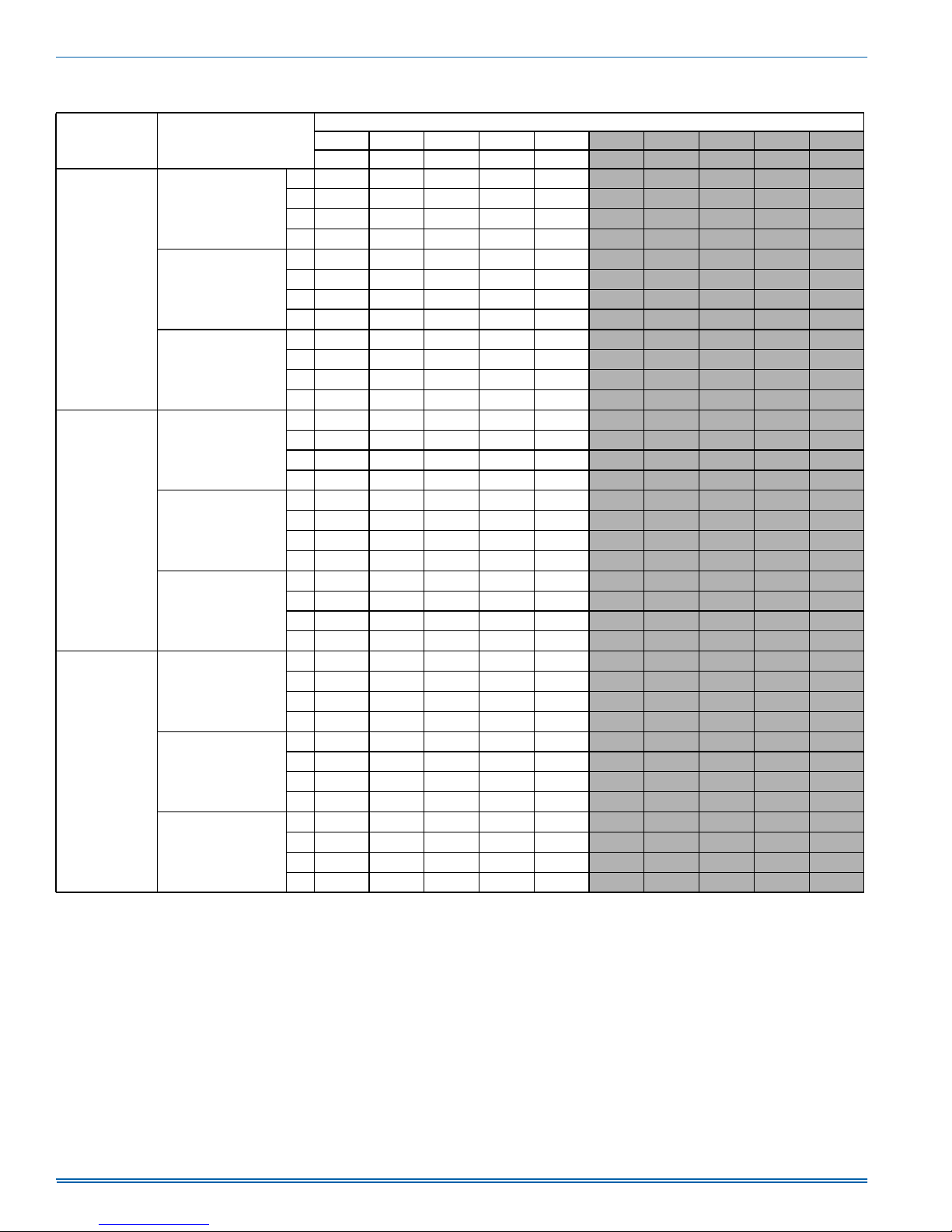
Table 10: Airflow Performance - Side Duct Application
External Static Pressure (Inches WC)
Model Jumper Position
High Cool/Heat
PHE6B36
Low Cool/Heat
Electric Heat
High Cool/Heat
PHE6B48
Low Cool/Heat
Electric Heat
High Cool/Heat
PHE6B60
Low Cool/Heat
Electric Heat
NOTES:
1.Airflow tested with dry coil conditions, without air filters, at 230 volts.
2.Applications above 0.8" w.c. external static pressure are not recommended.
3.Brushless DC high efficiency standard ECM blower motor used for all indoor blower assemblies.
4.Minimal variations in airflow performance data results from operating at 208 volts. Data above may be used in those cases.
5.Minimal variations in airflow performance data results from using downflow duct applications. Data above may be used in those cases.
6. Heating applications tested at 0.50" w.c. esp, and cooling applications tested at 0.30" w.c.esp per standards.
0.1 0.2 0.3 0.4 0.5 0.6 0.7 0.8 0.9 1.0
SCFM SCFM SCFM SCFM SCFM SCFM SCFM SCFM SCFM SCFM
A
1345 1318 1271 1222 1172
B
1264 1211 1170 1115 1056
C
1232 1178 1131 1077 1012
D
1058 999 931 859 762
A
1153 1095 1036 979 899
B
1015 952 884 802 709
C
882 805 741 625 556
D
805 718 642 523 436
A
1190 1133 1079 1026 953
B
1112 1054 991 928 840
C
955 886 821 721 642
D
856 776 708 591 516
A
1851 1809 1781 1746 1707
B
1689 1652 1630 1597 1556
C
1614 1578 1554 1520 1477
D
1374 1333 1298 1255 1204
A
1473 1435 1406 1368 1320
B
1374 1333 1298 1255 1204
C
1322 1278 1238 1191 1138
D
1286 1241 1197 1149 1095
A
1441 1407 1373 1325 1279
B
1327 1286 1242 1192 1143
C
1187 1136 1084 1028 968
D
1087 1031 974 909 832
A
2149 2114 2077 2030 1989
B
2013 1977 1941 1898 1860
C
1936 1900 1864 1822 1783
D
1719 1685 1642 1600 1555
A
1629 1591 1546 1502 1455
B
1558 1516 1469 1423 1375
C
1453 1406 1355 1305 1255
D
1410 1361 1307 1255 1204
A
1743 1712 1666 1623 1580
B
1485 1436 1380 1329 1283
C
1382 1324 1265 1210 1162
D
1205 1131 1066 1005 953
1108 1035 961 894 841
981 894 826 775 729
929 853 790 738 690
694 635 582 523 459
810 751 697 643 588
646 582 528 467 402
501 415 359 297 228
376 294 247 193 118
861 798 742 689 638
760 701 648 591 532
584 508 453 391 324
459 375 321 262 191
1656 1609 1552 1518 1460
1504 1461 1404 1368 1310
1424 1382 1324 1286 1228
1145 1100 1044 993 933
1264 1220 1164 1119 1060
1145 1100 1044 993 933
1077 1030 975 920 859
1032 984 930 872 810
1232 1182 1108 1042 1039
1081 1024 949 881 834
886 827 767 702 657
750 704 653 600 537
1948 1905 1859 1816 1768
1816 1772 1726 1677 1630
1739 1695 1649 1597 1551
1508 1465 1418 1372 1327
1409 1362 1315 1266 1220
1329 1280 1232 1181 1135
1207 1153 1100 1047 997
1155 1100 1044 992 938
1540 1493 1449 1404 1370
1234 1185 1139 1084 1032
1108 1059 1012 952 891
892 841 793 724 644
12 Johnson Controls Unitary Products
Page 13
5285477-UIM-A-1016
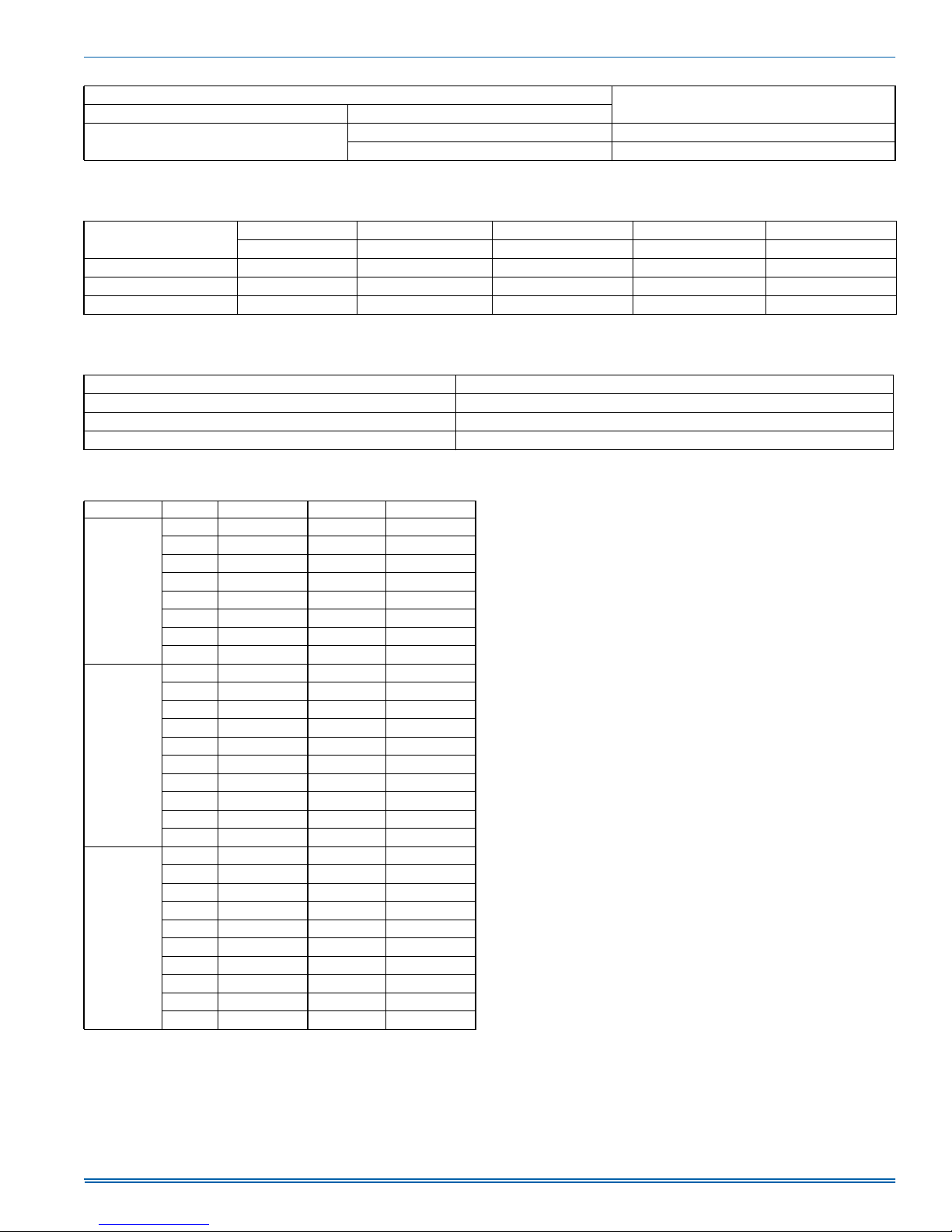
Table 11: Electric Heat Multipliers
Voltage
Nominal Applied
240
1. Electric heaters are rated at nominal voltage. Use this table to determine the electric heat capacity for heaters applied at lower voltages.
208 0.75
230 0.92
kW Capacity Multipliers
Table 12: Recommended Blower Speed for Electric Heat
Model
10 15 18 20 25
Heater kW
PHE6B36 C (ML) A (HI) -- -- -PHE6B48 D (LO) C (ML) B (MH) A (HI) -PHE6B60 D (LO) D (LO) C (ML) B (MH) A (HI)
NOTE: The recommended HEAT speed selections above will give approximately a 45 degree temperature rise at 0.3" static with 230V power supply. If lower or higher
heating airflow is desired, or if duct static or voltage are different than specified, other speed taps may be used.
Table 13: Electric Heat Blower Off Delay
Model ID Blower Off Delay In Seconds
PHE6B36 60
PHE6B48 110
PHE6B60 110
1
Table 14: Additional Static Resistance
Size (Tons) CFM Wet Indoor Coil Economizer
1
Filter/Frame Kit
700 0.01 0.00 0.04
800 0.02 0.01 0.06
900 0.03 0.01 0.08
36 (3.0)
1000 0.04 0.01 0.10
1100 0.05 0.01 0.13
1200 0.06 0.02 0.16
1300 0.07 0.03 0.17
1400 0.08 0.04 0.18
1100 0.02 0.02 0.04
1200 0.03 0.02 0.04
1300 0.04 0.02 0.05
1400 0.05 0.03 0.05
48 (4.0)
1500 0.06 0.04 0.06
1600 0.07 0.04 0.07
1700 0.07 0.04 0.08
1800 0.08 0.04 0.09
1900 0.09 0.05 0.10
2000 0.09 0.05 0.11
1100 0.02 0.02 0.04
1200 0.03 0.02 0.04
1300 0.04 0.02 0.05
1400 0.05 0.03 0.05
60 (5.0)
1500 0.06 0.04 0.06
1600 0.07 0.04 0.07
1700 0.07 0.04 0.08
1800 0.08 0.04 0.09
1900 0.09 0.05 0.10
2000 0.09 0.05 0.11
1. The pressure drop through the economizer is greater for 100% outdoor air
than for 100% return air. If the resistance of the return air duct is less than
0.25 IWG, the unit will deliver less CFM during full economizer operation.
2. Filter pressure drop based on standard filter media tested at velocities not
to exceed 300 ft/min.
SECTION VI: OPERATION
The unit is controlled by a heat pump heating/cooling thermostat.
If an electronic thermostat is used, make sure it has a common connec-
tion. DO NOT use a power stealing thermostat.
This unit has a multi-stage compressor, therefore the unit has two
stages of mechanical heat, and two stages of mechanical cooling. The
unit may be controlled using a single stage heat / single stage cool (1H/
1C) heat pump thermostat, but the second stage cooling or heating is
not available unless the unit control is physically wired for full capacity
operation. For optimum performance, it is recommend to use a four
stage heat / two stage cool (4H/2C) heat pump thermostat. If a 15 kW or
smaller heat kit is installed, use a three stage heat / two stage cool (3H/
2C) heat pump thermostat.
COOLING SEQUENCE OF OPERATION
A call for a compressor cooling signal from the thermostat is initiated at
the “Y1” terminal (for OD compressor) and the “O” terminal (for reversing valve).
The control cycles the compressor and indoor blower to second stage
cooling speed anytime a second stage cooling “Y2” call is received
during a first stage cooling “Y1” call. The control does not operate on
second stage cooling without a call on the “Y2” thermostat input.
1. On a call for cooling, the thermostat sends 24 volts to “Y” and “O” on
the defrost control board. The reversing valve solenoid is energized.
After the antishort cycle period is complete, the contactor coil “M” is
energized. Power is supplied to the compressor and outdoor fan
motor, and the reversing valve is switched to the cooling position.
The indoor blower is controlled by the indoor blower control board. It
operates on the “LOW COOL” or “HIGH COOL” speed based on the
24 VAC input from the defrost control board. If the control receives an
“O” input without a “Y” input, it energizes the reversing valve only.
2. When the demand for cooling has been satisfied, the 24 volt “Y”
signal is removed, and the contactor is de-energized. The indoor
blower motor continues to run and ramps down after a 60 second
delay.
Johnson Controls Unitary Products 13
Page 14
5285477-UIM-A-1016
Dehumidification/Humidity Switch Input
This model unit features a built in de-humidification feature for
advanced dehumidification during cooling operation. The unit indoor
blower control is designed to work with a humidity control that closes
when the humidity is below the set-point. The control is open when the
humidity is above the set-point. This humidity control may be referred to
as a humidistat or dehumidistat.
To use this feature, the control HUM STAT jumper must be set to YES
and a humidistat is connected from the low voltage R and HUM color
coded leads. During cooling operation if the humidity level is above the
humidistat set point, the indoor blower speed is reduced by approximately 15%.
Safety Controls
!
WARNING
The ability to properly perform maintenance on this equipment
requires certain expertise, mechanical skills, tools and equipment. If
you do not possess these, do not attempt to perform any maintenance other than those procedures recommended in this Installation
Manual. Failure to heed this warning could result in serious injury
and possible damage to this equipment.
The control circuit includes the following safety controls:
High Pressure Switch (HPS) - The switch protects against excessive
discharge pressures and the defrost control locks out compressor operation.
Loss of Charge Switch (LCS) - The switch protects against loss of
charge due to a leak in the system.
The above pressure switch is specifically designed to operate with R410A systems. R-22 pressure switches must not be used as replacements for the R-410A pressure switches.
Indoor Circulating Blower
When the thermostat calls for “FAN,” the thermostat terminal “G” is
energized signaling the indoor blower control board to operate the circulating blower to run continuously.
If a call for “COOL” occurs on “Y1,” the indoor blower runs at the “LOW
COOL” speed based on the “COOL” jumper setting. If a call for cool is
present on “Y1”+”Y2,” the indoor blower runs at the “HIGH COOL”
speed based on the “COOL” jumper setting.
If a call for “HEAT” occurs “W1” or “W1”+“W2”, the circulating blower
runs at the heat speed based on the “HEAT” jumper setting.
When the thermostat ends the call for “FAN,” the thermostat terminal
“G” is de-energized, and the indoor blower control board stops the circulating blower operation.
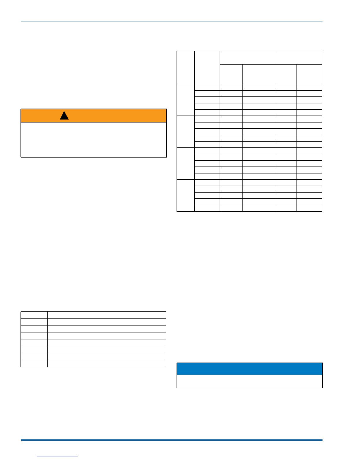
Table 15: Indoor Blower Control Fault Codes
Flashes Fault Condition
LAMP OFF No Power to control
LAMP ON Internal control failure
SLOW RED Control normal operation
RAPID RED Test Mode
7 RED Call for heat and cool at the same time
8 RED Model ID plug not inserted
9 RED Internal fault self corrected, attempting normal operation
Delay Profiles
The Delay Profiles for each Delay jumper setting are shown in Table 16.
The levels shown in the Pre-Run, Short-Run, and Run Periods are a
percentage of the fan speed corresponding to the thermostat call. The
Post-Run and Off Delay levels are derived from the level of the previous
state, not the fan speed corresponding to the thermostat call. If in Delay
Profile B and in the Short-Run Period (82% of capacity) and the thermo-
stat call is removed, this causes control to enter the Post-Run state.
The Post-Run state level for Delay Profile B is 100% of the previous
level, so the level during the Post-Run state is 82%.
TABLE 16 : Delay Profile Descriptions
Cooling
Delay
Profile
*The Post-Run and Off Delay levels are derived from the level of the
previous state, not the fan speed corresponding to the thermostat
call.
Period
Level%
Pre-Run Bypass Bypass Bypass Bypass
Short-Run Bypass Bypass Bypass Bypass
A
B
C
D
Run 100 No Limit 100 No Limit
Post-Run* 100 1 100 .5
Off Delay* Bypass Bypass Bypass Bypass
Pre-Run 50 2 Bypass Bypass
Short-Run 82 5 Bypass Bypass
Run 100 No Limit 100 No Limit
Post-Run* 100 1 100 .5
Off Delay* Bypass Bypass Bypass Bypass
Pre-Run Bypass Bypass Bypass Bypass
Short-Run Bypass Bypass Bypass Bypass
Run 100 No Limit 100 No Limit
Post-Run* 100 1 100 .5
Off Delay* 50 1 Bypass Bypass
Pre-Run Bypass Bypass Bypass Bypass
Short-Run 63 1.55 Bypass Bypass
Run 100 No Limit 100 No Limit
Post-Run* 100 1 100 .5
Off Delay* 63 0.5 Bypass Bypass
Time in State
(Minutes)
Heat Pump
Heating
Level%
Time in
State
(Minutes)
HEATING SEQUENCE OF OPERATION
1. On a call for heating, the thermostat sends 24 volts to “Y1” or
“Y1”+“Y2” on the defrost control board. After the anti-short cycle
period is complete, the 24 volt signal from “Y1” energizes contactor
coil “M” to supply power for the compressor and outdoor fan motor.
The indoor blower control operates the indoor blower motor at the
“LOW COOL” speed. If the 24 volt signal from “Y2” is present, the
defrost control board energizes the 2nd stage compressor solenoid
and signals the indoor blower control to operate the indoor blower
motor at the “HIGH COOL” speed. The reversing valve remains in
the heating position. Indoor blower speeds are selected by the
“COOL” jumper on the indoor blower control board.
2. If the heat pump cannot meet the heating demand using mechanical
(compressor) heating, the indoor thermostat may energize axillary
(electric) heating to supplement the mechanical heating if an electric
heat kit was field installed. The room thermostat sends a 24 VAC signal on “W1” or “W1”+“W2.” The “W1” signal is received by the indoor
blower control board which then energizes the “HT1” output for electric heat. When a call for mechanical heating and supplemental heating is present, the indoor blower control operates the indoor blower at
either the “Y1”+”Y2” or the “W1” speed whichever is higher based on
the “COOL” and “HEAT” jumper selection.
NOTICE
The “W1” must be energized with “W2” in order to enable indoor air
flow.
nd
A 2
stage auxiliary electric heating “W2” from the thermostat is to
be wired directly to the second stage heat kit input.
14 Johnson Controls Unitary Products
Page 15
5285477-UIM-A-1016
'()5267
&859(
6(/(&7,21
-803(5
7(673,16
67$786/('
3. When the heating demand is satisfied, the electric heat is de-energized when the 24 volt “W” signal is removed, and the “M” contactor
is de-energized when the 24 volt “Y” signal is removed.
When the fan switches on the thermostat is in the “ON” position, the
indoor blower continues to run. When the fan switch is in the
“AUTO” position, the indoor blower motor ramps down after the
blower off delay.
4. Refer to Table 13 for more information on electrical heat blower
OFF delay.
DEFROST OPERATION
The demand defrost control implements a temperature differential
(”delta-T”) demand defrost algorithm. The heat pump is allowed to operate in the heating mode until the combination of outdoor ambient and
outdoor coil temperatures indicate that defrosting is necessary. When
coil temperature is below the initiate point for the ambient temperature
continuously for 4-1/2 minutes, the heat pump is put into a defrost cycle.
This 4-1/2 minute timer eliminates unnecessary defrost cycles caused
by refrigeration surges such as those that occur at the start of a heating
cycle.
A timed inhibit feature prevents the system from responding to a call for
defrost less than 40 minutes after the initiation of the previous defrost.
After the 40 minute inhibit time has expired, temperature conditions
must call for defrost continuously for 4-1/2 minutes before a defrost
cycle is initiated. A temperature inhibit feature prohibits defrost if the coil
temperature is above 40°F.
A forced-defrost feature puts the system into a defrost period every 6
hours and 4 minutes of accumulated compressor run-time to recirculate
lubricants, unless the coil temperature is above 40°F and the ambient
temperature is above 50°F . All defrost timing occurs only while the compressor is on.
During the defrost mode, the reversing valve is energized, the outdoor
fan is de-energized, the compressor is energized, and the defrost control provides a 24 volt signal from terminal “W1OUT” to energize electric
heat stage 1 if the unit is equipped with electric heat.
By selecting “LO” on the “DEFROST HEAT” jumper, “W1 OUT” is energized during defrost. By selecting “HI” on the “DEFROST HEAT”
jumper, “W1 OUT” and “W2 OUT” are energized during defrost.
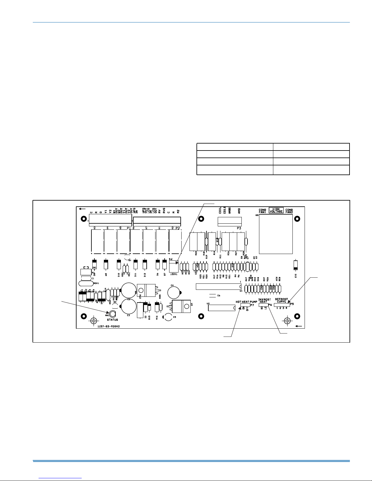
For trouble shooting purposes, the defrost cycle can be manually initiated by shorting the “TEST” pins together for 5 seconds while “Y” is
energized. After removing the short, defrost will terminate normally
during the “TEST” mode.
Table 17: Demand Defrost Selection
Unit Pin Position
048, 060 2
036 — 042 3
036 — 060
*
For extreme environments as necessary only.
*
4
FIGURE 8: Demand Defrost Control
Johnson Controls Unitary Products 15
+27+($738036(/(&7,21
'()52676833/(0(17$/
+($76(/(&7,21
$
Page 16
5285477-UIM-A-1016
,1'225$,5)/2:6(/(&7,21
67$786/('
$03&21752/)86(
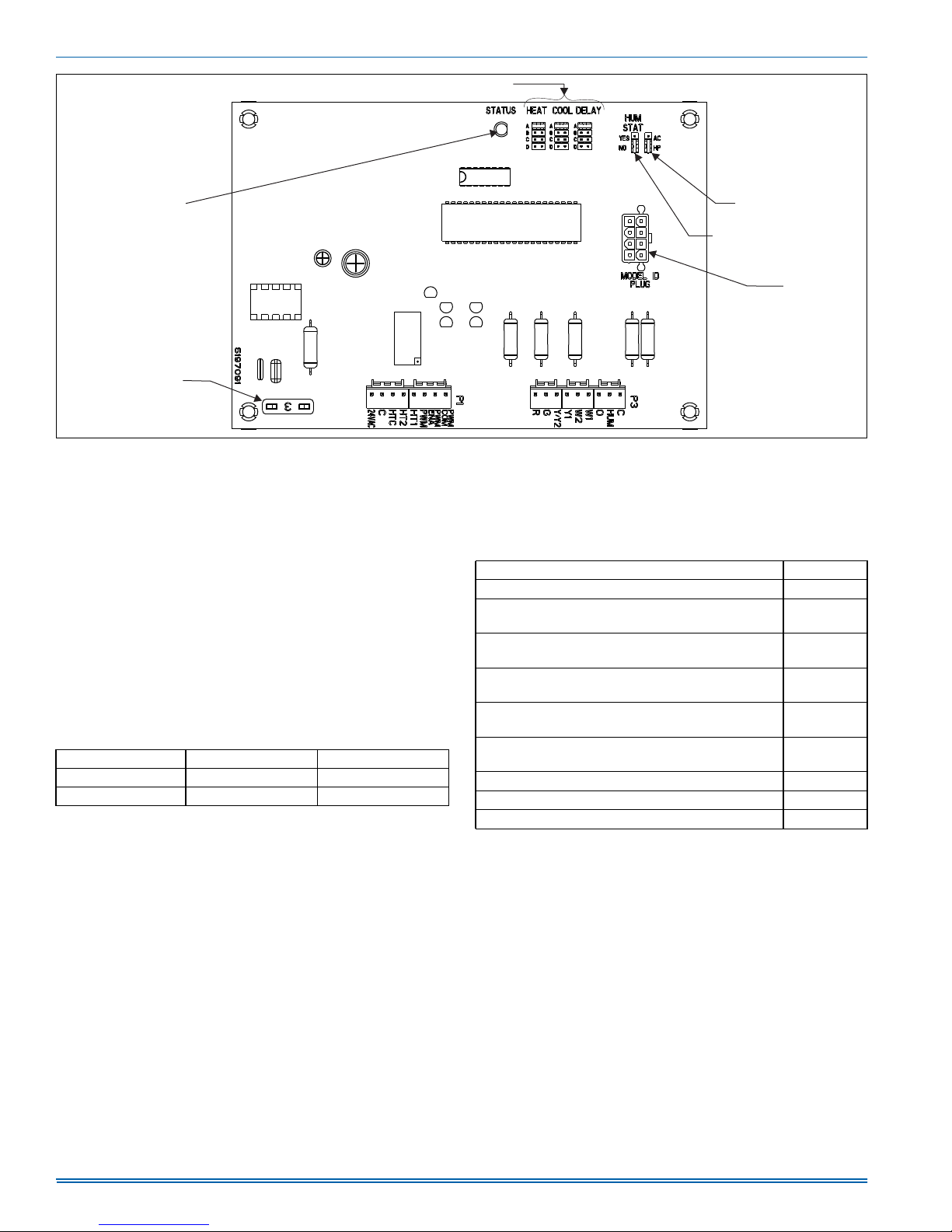
FIGURE 9: Blower Control
Heat Pump Safety Switch Operation
The unit is equipped with a safety package. The refrigeration system
will be protected against high refrigerant pressure and a loss of charge
switch. If either of these safety switches open, the unit will be shut off
for the 5 minute anti-short cycle time. Once this has expired, a six hour
elapsed run timer begins. If a second opening of a safety switch occurs
during this six hour period, the compressor will be locked out.
Resetting the lockout function is accomplished by:
1. Removing power from the control's thermostat 1st stage (Y) input for
longer than 2 seconds.
2. Removing power from “R” for more than 2 seconds.
3. Shorting the “TEST” pins together for more than 2 seconds while
“Y” is energized.
4. Shorting the “TEST” pins together for more than 5 seconds while
“Y” is de-energized.
Table 18: Test Pins
Test Pin Shorted With Y Call Without Y Call
greater than 2 sec Bypass ASCD Show error codes
greater than 5 sec Forced defrost Clear error codes
Demand Defrost Fault Code Display
The control provides fault codes using the Status LED display. Table 19
describes the LED displays for fault codes. On the LED display, the
control displays a single fault code only. The control displays the fault
code on the LED display repeatedly with a 2 second off period between
repetitions of the fault code. If multiple fault codes are present at the
same time, the LED displays only the highest priority fault. The other
active faults may be accessed via the LAST ERROR button on the control board.
$&+36(/(&7,21
'(+80,',67$76(/(&7,21
02'(/
,'3/8*
-803(5
$
Table 19 shows the LED display representation for specified faults. For
instance, a red LED display of 10 flashes indicates a control failure.
When any fault code is present, the control does not display the current
status code for the stage of operation.
Table 19: Demand Defrost Fault Codes
Description STATUS LED
High -pressure switch fault (not in lockout yet) 2 Flashes
System in high-pressure switch lockout (last mode of
operation was normal compressor)
System in high-pressure switch lockout (last mode of
operation was defrost)
System in loss of charge switch lockout (last mode of
operation was normal compressor)
Low Voltage (less than 19.2VAC) preventing further
relay outputs for greater than 2 seconds
Low Voltage (less than 16VAC) stopped current relay
outputs for greater than 2 seconds
3 Flashes
4 Flashes
5 Flashes
6 Flashes
7 Flashes
Liquid Line sensor failure (Open or Shorted) 8 Flashes
Outdoor ambient sensor failure (Open or Shorted) 9 Flashes
Control Failure 10 Flashes
Electric Heat Limit Switch Operation
The 6HK single phase heat kits utilize a normally closed line voltage
limit switch and a normally closed fusible link. If the fusible link opens, it
must be replaced with the appropriate OEM part and the cause must be
investigated and corrected.
16 Johnson Controls Unitary Products
Page 17
Table 20: Thermostat Signals
Signal State Board Function
G
W
G & W
G & Y
G, Y & O
ON Indoor blower instant on
OFF Indoor blower off after 60-second delay
Indoor blower instant on
ON
Electric heat stages on (if so equipped)
Electric heat stages off (if so equipped)
OFF
Indoor blower off after off delay
Indoor blower instant on in heating speed
ON
Electric heat stages on (if so equipped)
W OFF
Y OFF
G, Y & O
Electric heat stages off (if so equipped)
Indoor blower switches to continuous fan speed
Outdoor fan instant on
Indoor blower instant on in cooling speed
ON
Compressor on (after any anti-short cycle delay)
System operates in heat pump heating mode
Compressor instant off
Outdoor fan instant off
Indoor blower switches to continuous fan speed
Compressor instant off
G & Y
Outdoor fan instant off
OFF
Indoor blower off after 60 second delay
Outdoor fan instant on
Indoor blower instant on in cooling speed
Compressor on (after any anti-short cycle delay)
ON
Reversing valve energized
System operates in cooling mode
Compressor instant off
Outdoor fan instant off
Y & O
OFF
Reversing valve off
Indoor blower switches to continuous fan speed
Compressor instant off
Outdoor fan instant off
OFF
Reversing valve off
Per Delay Profiles Paragraph and Table 16
5285477-UIM-A-1016
STARTUP
1. Check the electrical supply voltage being supplied. Be sure that it is
within the specified range on the unit data plate.
2. Make sure all electrical connections are tight.
3. If unit is connected to 208 volt supply power, the control transformer
must be wired accordingly.
4. Turn unit electrical power on.
5. Set the room thermostat to COOL mode and lower the desired temperature setting lower than the room temperature to create a call for
cooling.
!
CAUTION
Scroll compressors require proper rotation to operate properly. Failure to check and correct rotation may result in property damage.
NOTICE
Three-phase, scroll compressors operate in only one direction. If the
scroll is drawing low amperage, has similar suction and discharge
pressures, or is producing a high noise level, the scroll is misphased.
6. Check compressor rotation. If the scroll is misphased, change the
incoming line connection phasing to obtain the proper rotation.
7. Measure the total system duct static, and set the blower motor cooling speed appropriately per airflow performance tables.
8. Make sure all unit panels are in place and secure and that an air filter is installed.
EXTERNAL STATIC PRESSURE SETUP
To measure external static pressure:
• Measure the supply air static pressure
• Record this positive number
• Measure the return air static pressure
• Record this negative number
• Treat the negative number as a positive and add the two numbers
together
• This is total system static
FIGURE 10: Measuring External Static Pressure
Johnson Controls Unitary Products 17
Page 18
5285477-UIM-A-1016
SECTION VII: MAINTENANCE
NORMAL MAINTENANCE
!
WARNING
Prior to any of the following maintenance procedures, shut off all
power to the unit, to avoid personal injury.
Periodic maintenance consists of changing or cleaning filters and general cleaning of the outdoor coil.
FILTERS - Inspect once a month. Replace Disposable or clean Permanent Type as necessary. DO NOT replace Permanent Type with Disposable.
MOTORS - Indoor and outdoor fan motors are permanently lubricated
and require no maintenance.
OUTDOOR COIL - Dirt should not be allowed to accumulate on the outdoor coil surface or other parts in the air circuit. Cleaning should be as
often as necessary to keep the coil clean. If water is used to clean the
coil, be sure that the power to the unit is shut off prior to cleaning.
NOTICE
DO NOT use a pressure washer as coil fin damage will occur.
!
CAUTION
Exercise care when cleaning the coil so that the coil fins are not damaged.
Do not permit the hot outdoor air discharge to be obstructed by overhanging structures or shrubs.
TROUBLESHOOTING
!
WARNING
Troubleshooting of components necessarily requires opening the
electrical control box with the power connected to the unit. Use
extreme care when working with live circuit! Check the unit nameplate for the correct range before making any connections with line
terminals.
!
CAUTION
The wire number or color and terminal designations referred to may
vary. Check the wiring label inside the control box access panel for
the correct wiring.
18 Johnson Controls Unitary Products
Page 19
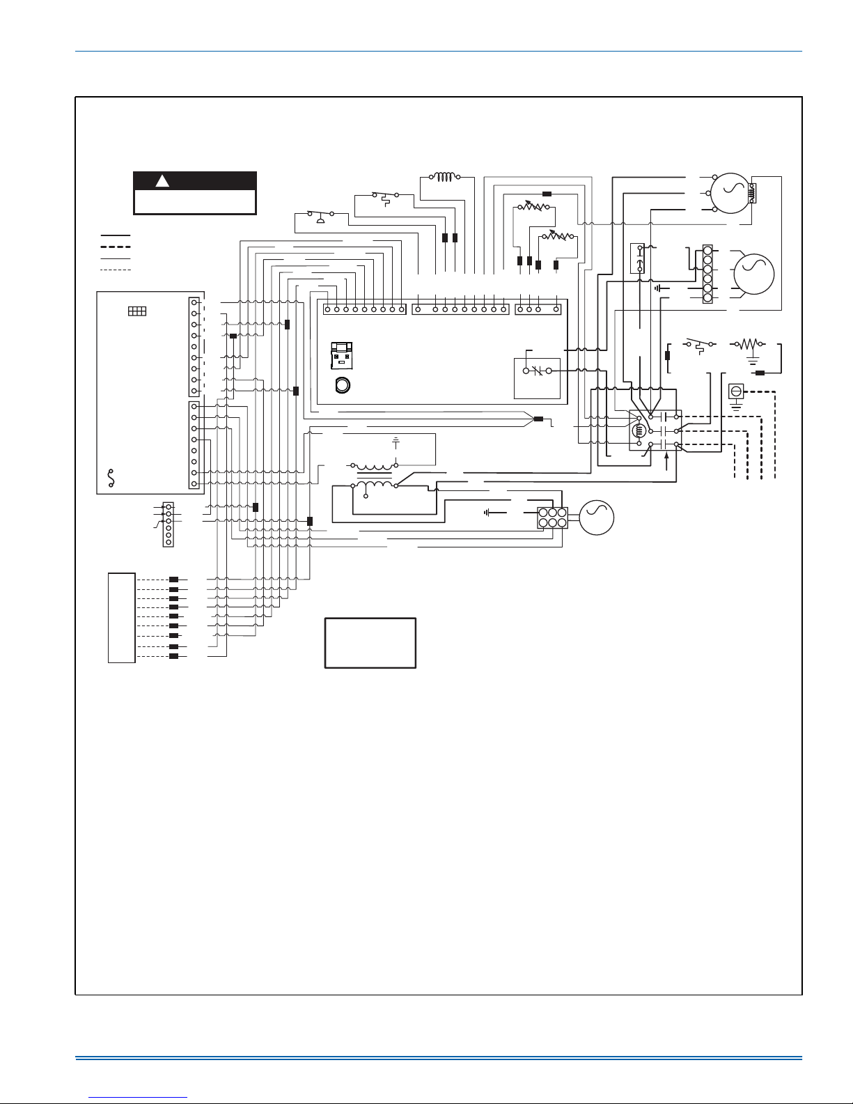
SECTION VIII: TYPICAL WIRING DIAGRAMS
2 STAGE HEAT PUMP WITH OR WITHOUT
ELECTRIC HEAT - 208/230-3-60
CONNECTION WIRING DIAGRAM
CAUTION
!
OPEN ALL DISCONNECTS
BEFORE SERVICING THIS UNIT.
208/230V LINE VOLTAGE
FIELD INSTALLED POWER
24V LOW VOLTAGE
FIELD INSTALLED CONTROL
P3
C
BLU (42)
HUM
Y/Y2
PWM
HT1
HT2
HT COM
24 VAC
6
WHT/BLK (44)
5
4
3
2
1
LOW
GRY (18)
O
ORN (41)
W1
WHT (46)
W2
Y1
YEL (48)
YEL/BLK (49)
G
GRN (19)
R
RED (50)
C
P1
WHT (45)
BLU (43)
BLU (27)
RED (25)
ORN (37)
YEL (36)
YEL/BLK (23)
GRN (19)
WHT/BLK (20)
WHT (21)
GRY (18)
MODEL ID
PLUG
2 STAGE
BLOWER
CONTROL
3A
FUSE
SECOND STAGE
RELAY / SEQUENCER
FIRST STAGE
RELAY / SEQUENCER
24V COMMON
FEMALE 6HK* ELEC. HEAT
KIT CONNECTOR
C
R
O
Y1
Y2
G
W2
W1
HUM
THERMOSTAT
VOLTAGE BOX
PWM COM
PWM ENA
Notes:
1. ALL FIELD WIRING TO BE ACCOMPLISHED FOLLOWING
CITY, LOCAL, AND/OR NATIONAL CODES IN EFFECT AT
THE TIME OF UNIT INSTALLATION.
2. CAUTION: LABEL ALL WIRES PRIOR TO DISCONNECTION
WHEN SERVICING CONTROLS. WIRING ERRORS CAN CAUSE
IMPROPER AND DANGEROUS OPERATION. IF ANY OF THE
WIRING AS SUPPLIED WITH UNIT MUST BE REMOVED, IT
MUST BE REPLACED WITH TYPE 105 C 600 VOLT WIRE OR
EQUIVALENT AND CLEARLY RENUMBERED FOR IDENTIFICATION.
VERIFY PROPER OPERATION AFTER SERVICING.
3. FACTORY WIRED FOR 230 VOLT 3 PHASE SUPPLY POWER. FOR
208 VOLT 3 PHASE SUPPLY POWER, MOVE BLACK WIRES FROM
THE 230 VOLT TAP TO THE 208 VOLT TAP ON THE TRANSFORMER.
4. MOTORS ARE INHERENTLY PROTECTED.
5. SEE UNIT NAMEPLATE FOR MAXIMUM FUSE AND/OR CIRCUIT
BREAKER SIZE AND MINIMUM CIRCUIT AMPACITY.
FIGURE 11: Connection Wiring Diagram
YEL (48)
WHT (47)
HI PRESSURE
YEL/BLK (23)
YEL (36)
ORN (40)
RED (39)
1P
C
STATUS TEST
BLU (26)
BLU (30)
RED (33)
RED/WHT (51)
FOR THREE-PHASE POWER.
A SINGLE PHASE SUPPLY
LOSS OF CHARGE
YEL/BLK (41)
WHT/BLK (22)
R
O
Y1
Y2
W1 OUT
BLU (52)
24V SEC
75VA
XFMR
230V
208V
TRANSFORMER
BLU/WHT (7)
NOTICE
THIS UNIT IS WIRED
DO NOT CONNECT TO
REV. VALVE
YEL (13)
HPS IN
Y1 OUT
Y2 OUT
W2 OUT
2 STAGE
DEMAND DEFROST
CONTROL
GRN (31)
COM
PUR/WHT (6)
SOLENOID
COIL
SENSOR
BRN (15)
LT BLU (14)
RV
LCS OUT
BLK (1)
BLU (29)
BRN (15)
C
RVG
PUR (3)
YEL (38)
YEL/BLK (24)
M
M2
GRN (5)
BLU (16)
3
P2P
COIL
OUTDOOR
FAN RELAY
BLK (2)
BLU (16)
WHT (17)
AMBG
COILG
BLK/WHT (10)
YEL (13)
LT BLU (14)
LCS IN
HPS OUT
PUR (4)
Demand Defrost Control Fault Codes
Flashes Fault Condition
LAMP OFF
STEADY RED
SLOW RED
RAPID RED
No Power to control
Compressor operation active - Compressor
contactor energized.
Control normal operation - No call for compressor.
Control normal operation - ASCD (Anti Short Cycle
Delay) active
2 RED
High Pressure Switch fault (Not yet in lockout)
3 RED
System in high pressure switch lockout (Last mode
of operation was normal compressor)
4 RED
System in high pressure switch lockout (Last mode
of operation was defrost)
5 RED
System in low pressure switch lockout (Last mode
of operation was normal compressor)
6 RED
Low Voltage (<19.2 VAC) preventing further relay
outputs for >2 seconds
7 RED
Low Voltage (<16 VAC) stopped current relay
outputs for >2 seconds
8 RED
Liquid Line sensor failure (Open or Shorted)
9 RED
Outdoor ambient sensor failure (Open or Shorted)
10 RED
Control Failure
Blower Control Fault Codes
Flashes Fault Condition
LAMP OFF
LAMP ON
SLOW RED
RAPID RED
No Power to control
Internal control failure
Control normal operation
Test Mode
7 RED
Call for heat and cool at the same time
8 RED
Model ID plug not inserted
9 RED
Internal fault self corrected, attempting normal
operation
T
AMBIENT
SENSOR
BLU (28)
2
3
5
6
T
WHT (17)
AMB
1
4
1
ID BLWR
MOTOR
CAP
F
C
RED (12)
BLK/WHT (32)
CONTACTOR
5285477-UIM-A-1016
BLK
L1
3
YEL
L3
COMPR.
L2
BLU
BLU
BRN/WHT (9)
GRN (8)
RED (11)
TEMPERATURE
BLK
BLK/WHT (35)
L2
T2
L3
T3
T1
L1
SWITCH
BLK
1
2
BRN
3
4
GRN
5
6
RED
BLU
CRANKCASE
BLK
BLK (34)
USE COPPER
CONDUCTORS
POWER SUPPLY
208/230-1-60
OD FAN
MOTOR
HEATER
5291017-UWD-A-0916
1
BLK
ONLY
Johnson Controls Unitary Products 19
Page 20
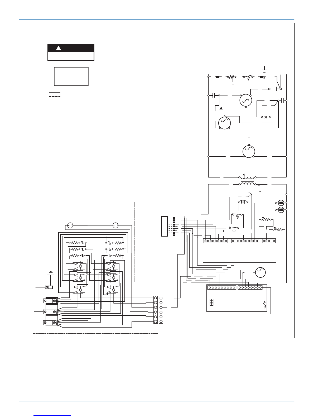
5285477-UIM-A-1016
2 STAGE HEAT PUMP WITH OR WITHOUT
CAUTION
!
OPEN ALL DISCONNECTS
BEFORE SERVICING THIS UNIT.
NOTICE
THIS UNIT IS WIRED
FOR THREE-PHASE POWER.
DO NOT CONNECT TO
A SINGLE PHASE SUPPLY
208/230V LINE VOLTAGE
FIELD INSTALLED POWER
24V LOW VOLTAGE
FIELD INSTALLED CONTROL
Notes:
1. ALL FIELD WIRING TO BE ACCOMPLISHED FOLLOWING
CITY, LOCAL, AND/OR NATIONAL CODES IN EFFECT AT
THE TIME OF UNIT INSTALLATION.
2. CAUTION: LABEL ALL WIRES PRIOR TO DISCONNECTION
WHEN SERVICING CONTROLS. WIRING ERRORS CAN CAUSE
IMPROPER AND DANGEROUS OPERATION. IF ANY OF THE
WIRING AS SUPPLIED WITH UNIT MUST BE REMOVED, IT
MUST BE REPLACED WITH TYPE 105 C 600 VOLT WIRE OR
EQUIVALENT AND CLEARLY RENUMBERED FOR IDENTIFICATION.
VERIFY PROPER OPERATION AFTER SERVICING.
3. FACTORY WIRED FOR 230 VOLT 3 PHASE SUPPLY POWER. FOR
208 VOLT 3 PHASE SUPPLY POWER, MOVE BLACK WIRES FROM
THE 230 VOLT TAP TO THE 208 VOLT TAP ON THE TRANSFORMER.
4. MOTORS ARE INHERENTLY PROTECTED.
5. SEE UNIT NAMEPLATE FOR MAXIMUM FUSE AND/OR CIRCUIT
BREAKER SIZE AND MINIMUM CIRCUIT AMPACITY.
WIRING DIAGRAM FOR
HEATER KIT:
6HK06501825
GND
L3
L2
L1
BLK
BLU
BLU
BLU
BLU
BLU
YEL
YEL
YEL
YEL
BLK
BLK
BLK
BLK
BLK
OPTIONAL ELECTRIC
HEATER ACCESSORY
SEE HEATER WIRING DIAGRAM FOR ALTERNATE
HEATER ACCESSORY KITS.
LS
HE6
HE3
HE2
YEL
RLY 6
BLU
RLY 5
BLK
RLY 4
YEL
BLU
BLU
FL
FL
FL
BLU
BLU
BLK
BLU
WHT
YEL
BLU
WHT
ELECTRIC HEAT - 208/230-3-60
LADDER WIRING DIAGRAM
Demand Defrost Control Fault Codes
Flashes Fault Condition
LAMP OFF
STEADY RED
SLOW RED
RAPID RED
RAPID RED
LS
FL
HE5
HE4
FL
HE1
FL
RLY 3
BLU
RLY 2
WHT
BLK
BLU
RLY 1
WHT
YEL
No Power to control
Compressor operation active - Compressor
contactor energized.
Control normal operation - No call for compressor.
Control normal operation - ASCD (Anti Short Cycle
Delay) active
2 RED
High Pressure Switch fault (Not yet in lockout)
3 RED
System in high pressure switch lockout (Last mode
of operation was normal compressor)
4 RED
System in high pressure switch lockout (Last mode
of operation was defrost)
5 RED
System in low pressure switch lockout (Last mode
of operation was normal compressor)
6 RED
Low Voltage (<19.2 VAC) preventing further relay
outputs for >2 seconds
7 RED
Low Voltage (<16 VAC) stopped current relay
outputs for >2 seconds
8 RED
Liquid Line sensor failure (Open or Shorted)
9 RED
Outdoor ambient sensor failure (Open or Shorted)
10 RED
Control Failure
Blower Control Fault Codes
Flashes Fault Condition
LAMP OFF
SLOW RED
No Power to control
LAMP ON
Internal control failure
Control normal operation
Test Mode
7 RED
Call for heat and cool at the same time
8 RED
Model ID plug not inserted
9 RED
Internal fault self corrected, attempting normal
operation
T-STAT
W1
W2
HUM
BRN
WHT
BLU
PUR
RED/WHT
BLK
6
6
5
5
4
4
3
3
2
2
1
1
VOLTAGE
C
R
O
Y1
Y2
G
WHT/BLK
WHT
BLU
LOW
BOX
BLU
RED
ORN
YEL
YEL/BLK
WHT
WHT/BLK
GRN
GRY
WHT
BLU
BLK
BRN/WHT
COM
XFMR
BLU
C
M
ID MOTOR
ID BLWR
MOTOR
HT2
HT COM
YEL
M2
1
C
3A
BLU
CAPACITOR
C
RED
YEL
YEL/BLK
COIL
SENSOR
BLU
3P
COIL
24 VAC
FUSE
GROUND
LUG
BLK/WHT
T3
RED
F
RUPKLB
PUR
BLU
BLU
T
BLU
WHT
AMBG
COILG
T2
CONT. COIL
2ND STAGE
COMPRESSOR
SOLENOID
T
AMBIENT
SENSOR
WHT
AMB
BLU
L2L3
CRANKCASE
T1
BLK/WHT
Y1
Y2
BLKBLK
GRN
1
OD FAN
MOTOR
BLK
W1 OUT
W2 OUT
BLU
YEL
YEL/BLK
Y1 OUT
Y2 OUT
HEATER
KLB
RED
YEL
PRES.
P
2
L1
WHT/BLK
WHT
ORN
RED
C
R
O
2 STAGE DEMAND DEFROST
RED
GRN
YEL/BLK
YEL
WHT
ORN
GRY
C
O
Y1
W1
W2
HUM
Y/Y2
PLUG
2 STG BLOWER
MODEL ID
CONTROL
BLK
COMPRESSOR
230V
BLU
VALVE
LOSS OF
CHARGE
YEL
HI
HPS IN
HPS OUT
CONTROL
R
G
PWM COM
3
ID BLWR
208V
24V SEC
BLU
REV.
LT. BLU
LT. BLU
LCS IN
LCS OUT
PUR/WHT
RED/WHT
PWM ENA
TEMP.
SWITCH
L3L1
L2
1
MOTOR
75VA
BRN
RV
BLU/WHT
PWM
GRN
BRN
RVG
HT1
5291017-UWD-A-0916
FIGURE 12: Ladder Wiring Diagram
20 Johnson Controls Unitary Products
Page 21
5285477-UIM-A-1016
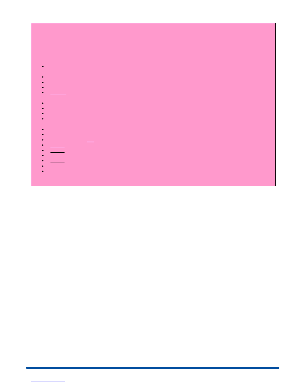
R-410A QUICK REFERENCE GUIDE
Refer to Installation Instructions for specific installation requirements
R-410A refrigerant operates at 50 - 70 percent higher pressures than R-22. Be sure that servicing
equipment and replacement components are designed to operate with R-410A.
R-410A refrigerant cylinders are rose colored.
Recovery cylinder service pressure rating must be 400 psig, DOT 4BA400, or DOT BW400.
Recovery equipment must be rated for R-410A.
DO NOT use R-410A service equipment on R-22 systems. All hoses, gages, recovery cylinders, charging
cylinders and recovery equipment must be dedicated for use on R-410A systems only.
Manifold sets must be at least 700 psig high side, and 180 psig low side, with 550 psig retard.
All hoses must have a service pressure rating of 800 psig.
Leak detectors must be designed to detect HFC refrigerants.
Systems must be charged with liquid refrigerant. Use a commercial type metering device
in the manifold hose.
R-410A can only be used with POE type oils.
POE type oils rapidly absorb moisture from the atmosphere.
Vacuum pumps will not remove moisture from R-410A refrigerant oils.
Do not use liquid line driers with a rated working pressure rating less than 600 psig.
Do not install suction line driers in the liquid line.
A liquid line drier is required on every unit.
Do not use a R-22 TXV. If a TXV is to be used, it must be a R-410A TXV.
Never open system to atmosphere when under a vacuum.
If system must be opened for service, evacuate system then break the vacuum with dry nitrogen
and replace all lter driers.
FIGURE 13: R-410A Quick Reference Guide
Johnson Controls Unitary Products 21
Page 22

5285477-UIM-A-1016
NOTES
22 Johnson Controls Unitary Products
Page 23
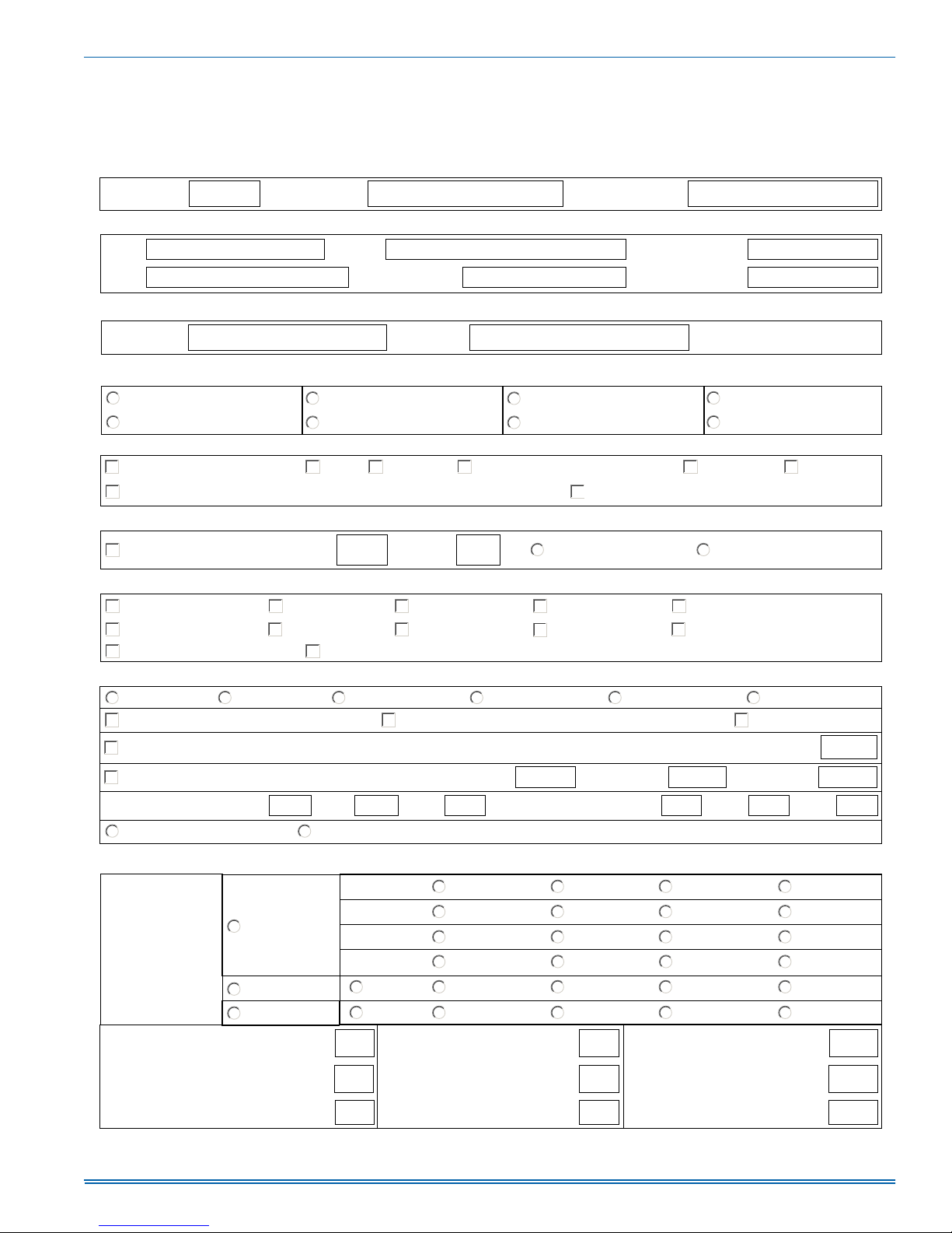
SECTION IX: START UP SHEET
Residential Package Unit Heat Pump
with Electric Heat Start-Up Sheet
Proper start-up is critical to customer comfort and equipment longevity
Start-Up Date
Owner Information
Name Address
City State or Province Zip or Postal Code
Equipment Data
Equipment Data
Unit Model # Unit Serial #
Start-Up TechnicianCompany Name
Daytime Phone
General Information
Residential
Commercial
Unit Location and Connections
Unit is level and installed on:
Condensate drain properly connected per the installation instructions Condensate trap has been primed with water
Filters
Filters installed Filter located inside Filter located outside
(Check all that apply)
New Construction
Retrot
(Check all that apply)
Slab Roof curb Supply Return
Number of lters Filter size
Roof level
Grade level
Duct connections are complete:
Down ow
Side ow
5285477-UIM-A-1016
Additional Kits & Accessories Installed
Refrigerant safety kit Low ambient kit
EconomizerTransformer kit Roof curb kit
Manual fresh air damper kit Motorized fresh air damper kit
Electrical Connections & Inspection
Three phaseSingle phase
Low voltage present at control board "R & C"
Line voltage present at disconnect
208 volts AC 230 volt AC 460 volts AC 575 volts AC
Measured voltage "L1 to L2" "L2 to L3" "L1 to L3"
Two stage compressorSingle stage compressor
(Check all that apply)
Anti-recycle timer
(Check all that apply)
Transformer wired properly for primary supply voltageInspect wires and electrical connections
Air Flow Setup
Blower Type
&
Set-Up
Variable
Speed
Standard ECM
PSC
COOL
ADJUST A B C D
DELAY
HEAT
1 2 3 4 5
Low Medium Low Medium Medium High High
Crank case heater
Burglar bar kit
Measured voltage "R" and "C" outdoor unit control board
Total amperes "L1" "L2" "L3"Compressor amperes "L1" "L2" "L3"
A B C D
A
A
B
B
Filter frame kit
Hail guard kit
Ground connected
C D
C D
Supply static (inches of water column) Supply air dry bulb temperature
Return static (inches of water column)
Total external static pressure
Johnson Controls Unitary Products 23
Return air dry bulb temperature
Temperature drop
Outside air dry bulb temperature
Return air wet bulb temperature
Supply air wet bulb temperature
Page 1 of 2 (7/7/16)
Page 24
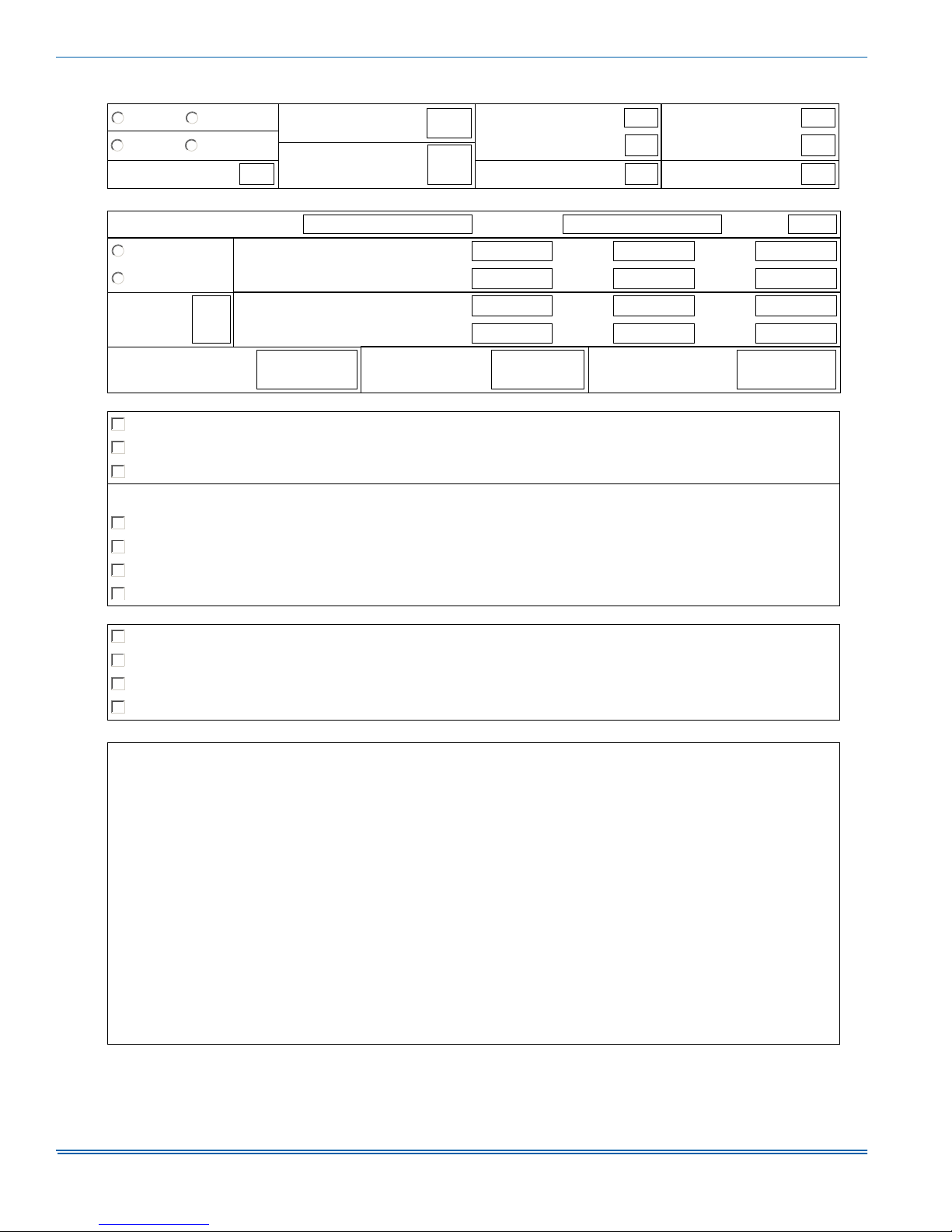
Refrigerant Charge and Metering Device
R-410A R-22
TXV Fixed Orice
TXV# / Orice size
Data plate - lbs / Oz
Discharge line
temperature
Suction line temperature
Suction pressure
Superheat
Discharge pressure
Liquid line temperature
Subcooling
Electric Heat (Supplemental and Emergency Heat)
Electric heat kit - Model number Serial number Rated KW
Single Phase
Measured Amperage
Three Phase
Heater 1
Heater 4
Heater 2
Heater 5
Heater 3
Heater 6
Number
of elements
Heating return air
dry bulb temperature
Measured Voltage
Heater 1
Heater 4
Heating supply air
dry bulb temperature
Heater 2
Heater 5
Air temperature rise
Clean Up Job Site
Job site has been cleaned, indoor and outdoor debris removed from job site
Tools have been removed from unit
All panels have been installed
Unit Operation and Cycle Test
Operate the unit through continuous fan cycles from the thermostat, noting and correcting any problems
Operate the unit through cooling cycles from the thermostat, noting and correcting any problems
Operate the unit through mechanical heating cycles from the thermostat, noting and correcting any problems
Operate the unit through emergency heating cycles from the thermostat, noting and correcting any problems
Owner Education
Provide owner with the owner's manual
Explain operation of system to equipment owner
Explain thermostat use and programming (if applicable) to owner
Explain the importance of regular lter replacement and equipment maintenance
Comments and Additional Job Details
Heater 3
Heater 6
Subject to change without notice. Published in U.S.A. 5285477-UIM-A-1016
Copyright © 2016 by Johnson Controls, Inc. All rights reserved. Supersedes: Nothing
Page 2 of 2 (7/7/16)
York International Corp.
5005 Y ork Drive
Norman, OK 73069
 Loading...