

Page 1

TECHNICAL GUIDE
®
SINGLE PACKAGE
AIR CONDITIONER / ELECTRIC HEAT
16 SEER – R-410A – 460V - 3 PHASE
3 THRU 5 NOMINAL TONS
MODELS: PCE6*36 THRU 60
®
Due to continuous product improvement, specifications
are subject to change without notice.
Visit us on the web at
www.upgnet.com and www.york.com
Additional rating information can be found at:
www.ahridirectory.org
WARRANTY SUMMARY*
Standard 1-Year limited parts warranty.
Standard 5-Years limited compressor warranty.
*See limited warranty certificate in User’s Information Manual for details.
5324339-YTG-D-1117
DESCRIPTION
These packaged cooling/heating air conditioners are designed
for outdoor installation. Only utility and duct connections are
required at the point of installation.
FEATURES
• Operating Efficiency - The 3-4 ton PCE6 air conditioner
models are rated at 16.0 SEER and 12.5 EER for cooling
operation.
The 5 ton PCE6 air conditioner model is rated at 16.0 SEER
and 12.0 EER for cooling operation.
All PCE6 models utilize a multi-stage compressor for maximum comfort and efficiency.
• On Site Flexibility - All model sizes use a compact design
cabinet. Field convertible duct connections from side shot to
down shot allows the installer to have greater flexibility with
less inventory.
• Lower Installation Cost - Installation time and costs are
reduced by easy power and control wiring connections. The
small base dimension means less space is required on the
ground or roof. All units are completely wired, charged with
R-410A and tested prior to shipment. Test stations using a
state-of-the-art computerized process system are used to
insure product quality. Refrigerant charge and component
part numbers are verified via computers during assembly.
Vital run test statistics such as system pressure, motor currents, air velocity and temperature, unit vibration, and gas
system safeties are monitored and recorded by the system to
insure unit performance. Equal size side supply and return
duct connections allow easy connection of ducts to match
low crawl spaces without transition pieces.
• Utility Connections Made Easy - Electric utility access pro-
vided through the bottom or the side of the unit. Utility connections can be made quickly and with a minimum amount of
field labor. A field supplied and field installed electrical disconnect switch must be installed.
• Convertible Airflow Design - The bottom duct openings are
covered when they leave the factory, ready to be used for a
side supply/side return application. If a bottom supply/bottom
return application is desired, simply remove the two panels
from the bottom of the unit and place them in the side supply/
side return duct openings. No panel cutting is required and
no accessory panel is necessary. Convertible airflow design
allows maximum field flexibility and minimum inventory.
• Condensate Pan - A corrosion-resistant, long-lasting, watertight pan is positioned below the evaporator coil to collect
and drain all condensate, preventing build-up of stagnant
condensate. The condensate pan conforms to ASHRAE 6289 standards (Ventilation for Acceptable Indoor Air Quality).
• Condensate Drain - The 3/4 inch NPT female connection is
rigidly mounted to assure proper fit and leak tight seal.
Continued on next page.
FOR DISTRIBUTION USE ONLY - NOT TO BE USED AT POINT OF RETAIL SALE
Page 2

5324339-YTG-D-1117
• Durable Finish - The cabinet is made of G90 galvanized
steel with a powder paint coating for appearance and protection. The pre-treated galvanized steel provides a better paintto-steel bond, which resists corrosion and rust creep. Powder paint finish ensures less fading when exposed to sunlight, and provides superior corrosion resistance (1000 hour
salt spray tested).
• Full Perimeter Base Rails - The easily removable base rails
provide a solid foundation for the entire unit and protects the
unit during shipment. The rails provide fork lift access from
all sides, and rigging holes are also provided so that an overhead crane can be used to place the units on a roof. On
applications where the unit is placed on a pad, the base will
keep the unit off the pad to deter corrosion. On applications
where height is limited, the base rails may be removed by
removing 2 screws in each corner.
• Attractive Appearance - A single-piece top cover containing
a top-discharge condenser fan arrangement requires less
square footage on installation and provides a wider variety of
installations. The one-piece design adds greater water integrity . Rounded corners with water drip edges add to the attractive appearance.
• Top Discharge - The top-discharge outdoor fan does not
disrupt neighboring areas or dry out vegetation surrounding
the unit. The warm air from the top mounted fan is blown up
and away from the structure and any landscaping.
• Outdoor Coil Grille - All models utilize a stamped slotted
design which provides superior impact protection against
small objects during transit and after installation.
• Low Operating Sound Level - The upward air flow carries
the normal operating noise up and away from the living area.
The rigid top panel effectively isolates noise. Isolator
mounted compressor and the rippled fins of the outdoor coil
muffle the normal fan motor and compressor operating
sounds. The unique formed base pan also aids in sound
attenuation with its structural design.
• Fan System - All models operate over a wide range of
design conditions with an enhanced ECM indoor fan motor.
These units easily match all types of applications and provide greater on-site flexibility to match comfort requirements.
The cooling speed is factory-set and can be field-adjusted to
a second speed. The heating speed is factory set to maintain
mid point rise at the units heating input, but can be field
adjusted. This allows maximum comfort conditions.
• Dehumidification/Humidity Switch Input - This model unit
features a built in de-humidification feature for advanced
dehumidification during cooling operation. The unit indoor
blower control is designed to work with a humidity control
that closes when the humidity is below the set-point. The
control is open when the humidity is above the set-point. This
humidity control may be referred to as a humidistat or dehumidistat.
To use this feature, the control HUM STAT jumper must be
set to YES and a humidistat is connected from the low voltage R and HUM color coded leads. During cooling operation
if the humidity level is above the humidistat set point, the
indoor blower speed is reduced by approximately 15%.
• Simple Control Circuit - Field thermostat wiring connect to
color coded leads using twist on wire connections. Cooling
controls use a contactor and a 2nd stage 24 VAC to 24 VDC
rectifier for simple application and troubleshooting. Mate-nlock plug connectors are used. Enhanced ECM indoor
blower control is managed by a multi-stage indoor blower
control board that includes field adjustable speed tap jumpers for maximum flexibility and product application. The
electrical control box is not located in the compressor compartment. The controls are mounted to allow the separate
access panel to be removed for trouble shooting and maintenance without affecting the normal system operating pressures. All wiring internal to the unit is color/number coded.
• Protected Compressor - The compressor is internally pro-
tected against high pressure and temperature. This is
accomplished by the simultaneous operation of scroll bypass
and a temperature sensor which protect the compressor if
undesirable operating conditions occur.
• Pressure Switches - A high pressure switch is standard in
all units. It is an automatic reset switch. When discharge
pressure reaches 650 psi, the compressor will de-energize
until pressure reaches 450 psi.
• Loss of Charge Switch - All models include a loss of charge
switch to provide safe shutdown of compressor.
• Exclusive Coil Design - Grooved copper tubes and
enhanced aluminum fin construction improves heat transfer
for maximum efficiency and durability for long-lasting durability and efficient operation. Indoor coils will use tin-coated
copper tubing with aluminum fins for effective heat transfer.
• Electric Heat - All PCE models use 6HK electric heat, which
are available in 460V/3/60 from 10 kW to 25 kW. Single point
field wiring kits are available for all applications.
• Low Maintenance - Long life, permanently lubricated indoor
and outdoor fan motor bearings need no annual maintenance, adding greater reliability to the unit. Slide-out blower
assembly and indoor coil assembly can be easily removed
for cleaning.
• Easy Service Access - Individual access panels are pro-
vided in access to all major components - compressors,
indoor coils, blower, controls/electric heat kits, filters, etc.
that makes servicing easy. Removing these panels allow
easy removal of the components such as the blower assembly for maintenance and ease of troubleshooting.
• Replacement Parts - The installer requires no special train-
ing to replace any of the components of these units and the
number of new components have been reduced to minimize
the inventory of unique parts.
• Filter Frame Kit - All 3 phase PCE6 units include a filter
frame kit, which is shipped inside the unit from production.
Field installation is required.
• Filters - All 3 phase PCE6 units include an applicable num-
ber of 1" washable filters, which are shipped inside the unit
from production. Field installation is required. Three filters
are required for B base units.
2 Johnson Controls Unitary Products
Page 3
5324339-YTG-D-1117
NOMENCLATURE
PCE 4 A 24 50 2 X 1 A
123456789
1. Model Family
PCG - packaged A/C with gas heat,
PHG - packaged heat pump with gas heat,
PCE - packaged A/C with electric heat,
PHE - packaged heat pump with electric heat,
2. Nominal Cooling Efficiency
4 = 14 SEER, 6 = 16 SEER, etc.
3. Cabinet Size
A = small 35 x 51, B = large 45 x 51
4. Nominal Air Conditioning Cooling Capacity BTUx1000
24 = 24,000 BTU, etc.
Examples:
PCE6B4221A is a packaged A/C with electric heat, 16 SEER, 3-1/2 ton, large cabinet, 230 volt, single phase, low-NOx model (first generation, first release).
5. Gas Heating Input BTU/Hr x 1000
050 = 50,000 BTU/Hr. input, blank = electric heat
6. Voltage-Phase-Frequency
2 = 208/230-1-60, 3=208/230-3-60, 4 = 460-3-60
7. NOx Approval
X = low-NOx, blank = not low-Nox
8. Generation Level
1 = first generation
9. Revision Level
A = original release, B = second release
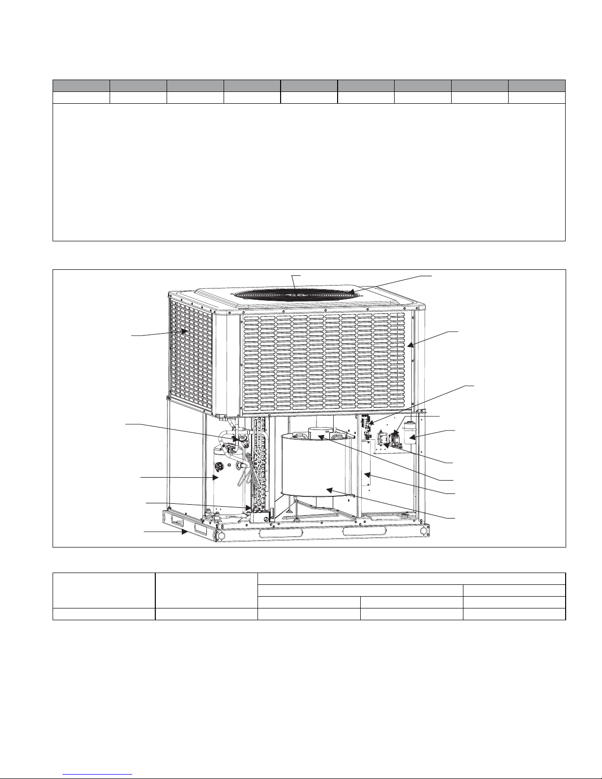
COMPONENT LOCATION
287'225&2,/
%HKLQG3DQHO
7;9
&2035(6625
,1'225&2,/
5(029$%/(
%$6(5$,/6
287'225)$102725
287'225)$1
&2,/*8$5'3$1(/
(&0)$102725
&21752/%2$5'
&217$&725
&$3$&,725
75$16)250(5
%/2:(502725
237,21$/
(/(&75,&+($7.,7
,1'225%/2:(5
$
UNIT LIMITATIONS
Model Unit Voltage
All Models 460-3-60 432 504 125
Johnson Controls Unitary Products 3
Unit Limitations
Applied Voltage Outdoor DB Temp
Min Max Max (°F)
Page 4

5324339-YTG-D-1117
ACCESSORIES
• Economizer for Downflow Applications
(S1-2EE04710024, S1-2EE04710124) - Modulating inte-
grated economizer provides simultaneous operation between
mechanical cooling and economizer operation. Independent
blade design insures proper control and less than 1% leak
rate. Includes hood and mesh bird screen filter integrated into
the hood, dry bulb sensor and relief damper. Separate field
accessories of single/dual enthalpy kits are also available.
• Economizer for Horizontal Applications
(S1-2EE04710224, S1-2EE04710324) - Modulating integrated economizer provides simultaneous operation between
the mechanical cooling and economizer operation. Independent blade design insures proper control and less than 1%
leak rate. Includes hood and mesh bird screen filter integrated into hood, dry bulb sensor and relief damper. Separate
field accessories of single enthalpy and dual enthalpy are
available.
• Single/Dual Enthalpy Sensor (S1-HE-6863-0N00WS) -
Sensor replaces supply air temperature dry bulb sensor standard in economizer kit. Provides improved economizer operation by sensing the dry bulb temperature of indoor supply air
plus the enthalpy content of the outdoor air.
• Duct/Unit Mount CO2 Kit (S1-2AQ04700924) - Sensor kit
detects CO2 levels automatically and overrides the economizer when CO2 levels rise above the preset limits.
• Wall Mount CO2 Kit (S1-2AQ04701024) - Sensor kit detects
CO2 levels automatically and overrides the economizer when
CO2 levels rise above the preset limits.
• Supply Air Temperature Sensor Kit (S1-TE-63616E-2D) -
Outdoor supply air temperature sensor kit used with economizers.
• Filter/Frame Kit (Kit provided)
(S1-1FF0602, S1-1FF0601) - Kit contains the necessary hardware to field install return air filters into the base unit. The filter
rack is suitable for either 1" or 2" filters.
• Filter (S1-02647812000) - Washable 1” filter. Three filters
are required for B base units. Washable filters are included
inside shipped units for field installation.
• Motorized Fresh Air Damper
(S1-2MD04705224, S1-2MD04705124) - Designed for duct
mounted side supply/return and unit mounted down supply/
return applications. Damper capable of providing 0% through
50% of outdoor air (field supplied). Closes on power loss,
includes hood and screen assembly.
• Rectangle to Round (Horizontal) Adapter
(S1-1AK0110, S1-1AK0111) - Kit includes one supply and
one return air rectangle to round duct adapter. Adapters are
preformed and designed to fit over current horizontal duct
openings on the base unit. Transition is from rectangle to 12"
round for the 1AK0110 kit and from rectangle to 14" round for
the 1AK0111 kit.
• Rectangle to Round (Downflow) Adapter
(S1-1AK0108, S1-1AK0109) - Kit includes one supply and
one return air rectangle to round duct adapter. Adapters are
preformed and designed to fit into current downflow duct
openings on the roof curb. Transition is from rectangle to 16"
round for the 1AK0108 kit and from rectangle to 18" round for
the 1AK0109 kit.
• Roof Curbs (S1-1RC0503, S1-1RC0501) - NRCA approved
curbs provide proper fit to base unit for rooftop installations.
Curbs are designed to be assembled through hinge pins in
each corner. Kit also provides seal strip to assure an air tight
seal. These are 8 inch high roof curbs.
• Roof Curbs (S1-1RC0504, S1-1RC0502) - NRCA approved
curbs provide proper fit to base unit for rooftop installations.
Curbs are designed for assembly through hinge pins in each
corner. Kit also provides seal strip to assure air tight seal.
These are 14 inch high roof curbs.
• Transition Curb Kits (S1-1TC01*) - Adapter kits to allow
field use of pre-existing installed roof curbs to match PCE6
footprint to Affinity roof curbs, Carrier, Trane, or Goodman
curb footprints. Curb adapters are optional for current generation Carrier replacements but are recommended for previous
generation applications. Refer to the PCE6 price pages for
more details.
• Electric Heat (Optional) - All PCE models use 6HK electric
heat kits, which are available in 460V/3/60 from 10 kW to 25
kW. Single point field wiring kits are available for all applications.
• Manual Outdoor Damper (S1-1FA0502, S1-1FA0501) - Pro-
vides 0% through 50% outdoor air capability (field adjustable). Designed for duct mounted side supply/return
applications and unit mounted down supply/return applications. Includes hood and screen assembly.
• Transformer Kit (S1-2EC06700124) - Kit provides necessary hardware to provide single phase models from factory
furnished 40 VA transformer capability to 75 VA transformer
capability. (Required on installations with economizer or
motorized damper).
• Loss of Charge Switch (S1-2LC00024) - Kit provides Loss of
Charge switch and wiring to provide safe shutdown of compressor.
• Low Ambient Temperature Kit (S1-2LA04701024) - Kit provides necessary hardware to convert unit to operate in cooling cycle down to 0º F. Standard unit operation 45º F.
• Base Rail Hole Cover Kit (S1-1HC0101) - Kit provides necessary hardware to close off openings in base rails to block
off openings, i.e. prevent animal entrance.
• Single Point Wiring Kits for 6HK Electric Heat Applica-
tions (S1-SPWK*) - Kits provide field option for connecting
electrical power supplies to the field installed 6HK heat kits to
allow single point connections for single phase electric heat
applications with the exception of 25 kW kits.
• Thermostat (S1-THXU280*) - Compatible thermostat controls are available through accessory sourcing. For optimum
performance, these outdoor units are fully compatible with the
York
Hx™ Touchscreen Thermostat (S1-THXU280*) available through Source1. For more information, see the thermostat section of the Product Equipment Catalog.
• Wall Thermostat - The units are designed to operate with
standard, 24-volt electronic non power stealing and electromechanical thermostats. All units require the use of a multistage conventional thermostat.
* For additional kit numbers refer to the price pages.
4 Johnson Controls Unitary Products
Page 5

5324339-YTG-D-1117
GUIDE SPECIFICATIONS
GENERAL
Units shall be manufactured by Unitary Products in an ISO
9001 certified facility. These packaged cooling and heating air
conditioners are designed for outdoor installation. Only utility
and duct connections are required at the point of installation. Air
Conditioning units provide electric cooling and electric heating,
with field installed electric heat kits from 10 kW to 25 kW for
heating operation.
DESCRIPTION
Units shall be factory-assembled, single packaged, Air
Conditioners with Electric Cooling/Electric Heating units,
designed for outdoor installation. They shall have built in, equal
size, field convertible duct connections for supply/return or
horizontal supply/return. The units shall be factory wired, piped,
charged with R-410A Refrigerant and factory tested prior to
shipment. All models shall be rated in accordance with DOE
and AHRI test procedures for both heating and cooling
operation. Units shall be CSA listed to the UL 1995/CAN/CSA
No. 236-M90 standards.
• Operating Efficiency - All models shall be rated at a minimum of 16.0 SEER and 12.0 EER for cooling and heating
operation rated in accordance with DOE requirements.
• Low Operating Sound Level - The upward air flow carries
the normal operating noise up and away from the living area.
The rigid top panel effectively isolates noise. Isolator
mounted compressor and the rippled fins of the condenser
coil muffle the normal fan motor and compressor operating
sounds. The unique formed base pan also aids in sound
attenuation with its structural design. Sound ratings as tested
under AHRI test procedures shall be less than 77 dbA for all
models.
UNIT CABINET
Unit cabinet shall be a single piece design, with drip edges and
no-seam corners to provide optimum water integrity. Unit shall
have a rigidly mounted condenser coil guard to provide
protection from objects and personnel after installation. Indoor
blower section shall be insulated with foil-faced or foam
insulation, fastened to prevent insulation from entering the air
stream. Cabinet panels shall be separate, easily removable for
servicing and maintenance. Unit shall be built on a formed,
design base pan, with embossments at critical points to add
strength and rigidity and to aid in minimizing sound. Full
perimeter base rails shall be provided to assure reliable transit
of equipment, overhead rigging, for truck access and proper
sealing on roof curb applications. Base rails shall be easily
removable, when required to lower unit height. Filters shall be
factory furnished and be accessible through a removable
access door, sealed airtight. Units vertical discharge and return
duct configuration shall be designed to fit between standard 24”
O.C. beams without modification to building structure, duct work
and base unit.
• Durable Finish - The cabinet shall be is made of G90 galvanized steel with a powder paint coating for appearance and
protection. The pre-treated galvanized steel shall provide a
better paint-to-steel bond, which resists corrosion and rust
creep. Powder paint finish shall provide superior corrosion
resistance (1000 hour salt spray tested).
• On Site Flexibility - All model sizes shall use a compact
design cabinet. Field convertible duct connections from side
shot to down shot allows the installer to have greater flexibility with less inventory.
• Attractive Appearance - A single-piece top cover containing
a top-discharge condenser fan arrangement shall be used
which requires less square footage on installation and provides a wider variety of installations. The one-piece design
adds greater water integrity. Rounded corners with water drip
edges add to the attractive appearance and prevent water
penetration.
• Convertible Airflow Design - The bottom duct openings are
covered when they leave the factory, ready to be used for a
side supply/side return application. If a bottom supply/bottom
return application is desired, simply remove the two panels
from the bottom of the unit and place them in the side supply/
side return duct openings. No panel cutting is required and
no accessory panel is necessary. Convertible airflow design
allows maximum field flexibility and minimum inventory.
• Utility Connections Made Easy - Electric utility access shall
be provided through the bottom or the side of the unit. Utility
connections should be made quickly and with a minimum
amount of field labor. A field supplied and field installed electrical disconnect switch must be installed.
• Easy Service Access - Individual access panels are provided in access to all major components - compressors,
indoor coils, blower, controls/electric heat kits, filters, etc.
that makes servicing easy. Removing these panels allow
easy removal of the components such as the blower assembly for maintenance and ease of troubleshooting.
• Top Discharge - The top-discharge outdoor fan does not
disrupt neighboring areas or dry out vegetation surrounding
the unit. The warm air from the top mounted fan is blown up
and away from the structure and any landscaping.
• Outdoor Coil Grille - All models utilize a stamped slotted
design which provides superior impact protection against
small objects during transit and after installation.
Indoor Blower Assembly - Fan shall be direct drive design.
Fan wheel shall be double-inlet type with forward-curved
blades, dynamically balanced to operate smoothly throughout
the entire range of operation. Airflow design shall be constant
air volume. Bearings shall be sealed and permanently
lubricated for longer life and no maintenance. Fan assembly
shall be a slide-out design for easy removal and cleaning.
Indoor blower motors shall be equipped with a high efficiency
brushless DC motor (constant torque) also known as an
enhanced ECM motor.
Outdoor Fan Assembly - The outdoor fan shall be of the
direct-driven propeller type, discharge air vertically, have
aluminum blades riveted to corrosion resistant steel spider
bracket and shall be statically balanced for smooth operation.
The outdoor fan motor shall be totally enclosed with
permanently lubricated ball bearings and internally protected
against overload conditions.
Johnson Controls Unitary Products 5
Page 6

5324339-YTG-D-1117
REFRIGERANT COMPONENTS
• Protected Compressor - The compressor shall be a fully
hermetic type, direct drive compressor, that is internally protected against high pressure and temperature. This is
accomplished by the simultaneous operation of scroll bypass
and a temperature thermal overload sensor which protect the
compressor if undesirable operating conditions occur. The
hermetic motor shall be suction gas cooled and have a voltage range of +/- 10% of the unit nameplate voltage. Compressors shall have internal isolation and sound muffling to
minimize vibration and noise, and be externally isolated on a
dedicated, independent mounting.
• Indoor Coils - Indoor coils shall be of the direct expansion,
draw through design and have aluminum plate fins mechanically bonded to seamless internally enhanced tin-coated
copper tubes with all joints brazed.
• Condensate Pan - A corrosion-resistant, long-lasting, watertight pan is positioned below the indoor coil to collect and
drain all condensate, preventing build-up of stagnant condensate. The condensate pan conforms to ASHRAE 62-89
standards (Ventilation for Acceptable Indoor Air Quality).
• Condensate Drain - The 3/4 inch NPT female connection is
rigidly mounted to assure proper fit and leak tight seal.
• Outdoor Coils - Outdoor coils shall have aluminum plate
fins mechanically bonded to seamless internally enhanced
copper tubes with all joints brazed, and be a draw through
design.
Refrigerant Circuit and Refrigerant Safety Components
shall include: Thermal expansion devices (TXV's) shall be
factory mounted and provided, Filter/strainer to eliminate any
foreign matter, reversing valves to control refrigerant flow.
CONTROLS
• Simple Control Circuit - Field thermostat wiring connects to
color coded leads using twist on wire connections. Cooling
controls use contactor and relays for simple application and
troubleshooting. Mate-n-lock plug connectors are used.
Enhanced ECM indoor blower control is managed by a multistage indoor blower control board that includes field adjustable speed tap jumpers for maximum flexibility and product
application. The electrical control box is not located in the
compressor compartment. The controls are mounted to allow
the separate access panel to be removed for trouble shooting and maintenance without affecting the normal system
operating pressures. All wiring internal to the unit is color/
number coded.
• Pressure Switches - A high pressure switch is standard in
all units. It is an automatic reset switch. When discharge
pressure reaches 650 psi, the compressor will de-energize
until pressure reaches 450 psi.
• Factory Testing - Installation time and costs are reduced by
easy power and control wiring connections. All units are
completely wired, charged with R-410A and tested prior to
shipment. Test stations using a state-of-the-art computerized
process system shall be used to insure product quality.
Refrigerant charge and component part numbers are verified
via computer bar code scans during assembly. Vital run test
statistics such as system pressure, motor currents, air velocity and temperature, unit vibration, and gas system safeties
are monitored and recorded by the system to insure unit performance. This data could be provided by serial number
tracking if requested.
• Electric Heat - All electric heat models use 6HK electric
heat, which are available in 4 60V/3/60 from 10 kW to 25
kW. Single point field wiring kits are available for all applications. Electric heat kits must be certified to UL 1995 standard
requirements.
6 Johnson Controls Unitary Products
Page 7
5324339-YTG-D-1117
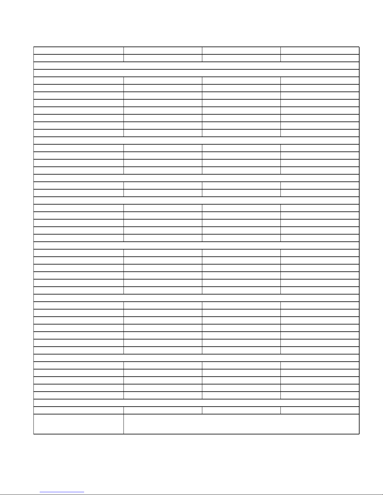
PHYSICAL DA TA
MODELS: PCE6B36 PCE6B48 PCE6B60
NOMINAL TONNAGE: 3.0 4.0 5.0
COMPONENT
AHRI Cooling Performance
Gross Capacity @ AHRI A point (MBH) 36.5 49.1 60.0
AHRI net capacity (MBH) 36.0 45.5 58.0
EER 12.5 12.0 12.0
SEER 16.0 16.0 16.0
Nominal CFM 1200 1600 2000
System power (KW) 3.0 3.6 4.6
Refrigerant type R410A R410A R410A
Refrigerant charge (lb-oz) 11-8 13-8 14-00
Dimensions (inches)
Length 51-1/4 51-1/4 51-1/4
Width 45-3/4 45-3/4 45-3/4
Height 49 53 55
Operating WT. (lbs.) 460 483 500
Compressors
Type Scroll Scroll Scroll
Stages 2 2 2
Outdoor Coil Data
Face area (Sq. Ft.) 19.5 23.8 25.9
Rows 2 2 2
Fins per inch 22 22 22
Tube diameter 3/8 3/8 3/8
Circuitry Type Interlaced Interlaced Interlaced
Indoor Coil Data
Face area (Sq. Ft.) 6.3 6.3 6.3
Rows 3 3 4
Fins per inch 16 16 16
Tube diameter 3/8 3/8 3/8
Circuitry Type Interlaced Interlaced Interlaced
Refrigerant control TXV TXV TXV
Outdoor Fan Data
Fan diameter (Inch) 26 26 26
Type Prop Prop Prop
Drive type Direct Direct Direct
No. speeds 1 1 1
Motor HP each 1/3 1/3 1/3
RPM 850 850 850
Nominal total CFM 3200 3200 3200
Direct Drive Indoor Fan Data
Fan Size (Inch) 11 x 10 11 x 10 11 x 10
Type Centrifugal Centrifugal Centrifugal
Motor HP each 1/2 1 1
RPM 1400 Max 1400 Max 1400 Max
Frame size 48 48 48
Filters
Filter Size B B B
Field-supplied external filters must be sized so as not to exceed 300 fpm air velocity through disposable fil-
Quantity - Size
ters. For internal filter use, a filter rack kit is available. Consult the instructions supplied with that kit for
replacement filter sizes. A=20 x 10 (2 each), B=20 x 10 (3 each)
Johnson Controls Unitary Products 7
Page 8
5324339-YTG-D-1117
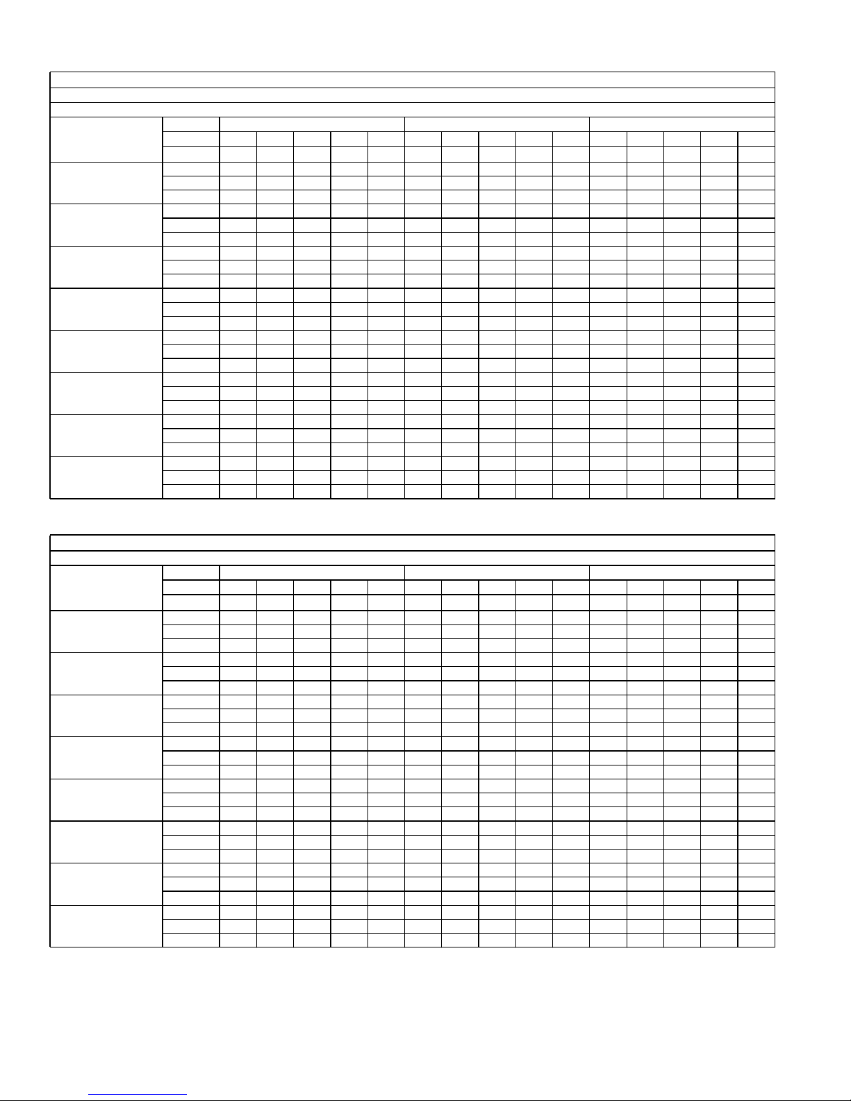
COOLING PERFORMANCE DATA - 3 TON (LOW SPEED)
PACKAGED UNIT MODEL NO. PCE6B36
INDOOR MODEL NO.
CONDENSER
ENTERING AIR
TEMPERATURE
55 / 45
65 / 55
75 / 63
85 / 69
95 / 75
105 / 83
115 / 89
125 / 95
ID CFM 600 800 1000
IDDB 80 80 75 80 80 80 80 75 80 80 80 80 75 80 80
IDWB 57 62 62 67 72 57 62 62 67 72 57 62 62 67 72
T.C. 34.8 41.4 41.7 46.0 49.1 37.3 41.2 41.5 44.6 47.3 39.7 41.0 41.2 43.1 45.4
S.C. 34.1 28.8 25.1 25.4 20.5 36.8 32.1 27.8 26.7 21.0 39.4 35.4 30.6 28.0 21.5
K.W. 2.35 2.20 2.19 2.16 2.13 2.30 2.16 2.16 2.13 2.11 2.25 2.13 2.13 2.11 2.09
T.C. 33.2 39.0 39.2 43.6 47.3 35.4 38.8 38.8 42.6 45.7 37.6 38.5 38.4 41.7 44.2
S.C. 32.4 27.6 23.7 24.2 19.5 34.8 30.7 26.3 25.9 20.3 37.3 33.9 28.9 27.6 21.2
K.W. 2.56 2.40 2.39 2.36 2.33 2.51 2.37 2.36 2.34 2.31 2.46 2.33 2.33 2.31 2.29
T.C. 31.5 36.6 36.7 41.2 45.5 33.5 36.3 36.1 40.7 44.2 35.4 36.0 35.6 40.2 42.9
S.C. 30.7 26.4 22.2 22.9 18.4 32.9 29.4 24.8 25.0 19.6 35.1 32.4 27.3 27.2 20.8
K.W. 2.77 2.61 2.59 2.57 2.52 2.71 2.57 2.56 2.54 2.50 2.66 2.53 2.54 2.51 2.48
T.C. 30.2 34.7 34.1 38.9 42.3 31.6 34.0 33.4 38.3 41.2 33.0 33.3 32.7 37.8 40.0
S.C. 29.1 25.1 21.0 21.6 17.0 30.9 28.3 23.5 24.0 18.2 32.7 31.4 25.9 26.4 19.4
K.W. 3.03 2.90 2.86 2.84 2.78 2.98 2.85 2.83 2.80 2.76 2.92 2.80 2.80 2.77 2.74
T.C. 28.8 32.7 31.5 36.6 39.2 29.6 31.7 30.6 36.0 38.1 30.5 30.7 29.8 35.4 37.1
S.C. 27.4 23.9 19.8 20.4 15.7 28.8 27.1 22.2 23.0 16.8 30.2 30.4 24.5 25.6 17.9
K.W. 3.29 3.20 3.13 3.11 3.05 3.24 3.13 3.09 3.07 3.02 3.19 3.06 3.06 3.03 2.99
T.C. 25.6 28.5 27.8 32.8 35.3 26.1 27.7 26.8 31.7 33.9 26.5 26.9 25.7 30.5 32.4
S.C. 23.7 21.5 17.5 18.5 13.9 25.0 24.1 19.8 20.8 14.8 26.3 26.7 22.2 23.2 15.8
K.W. 3.61 3.55 3.49 3.48 3.41 3.56 3.49 3.46 3.44 3.39 3.50 3.43 3.44 3.40 3.36
T.C. 22.5 24.4 24.2 29.1 31.6 22.6 23.8 23.0 27.5 29.8 22.7 23.2 21.8 25.8 27.9
S.C. 20.1 19.1 15.2 16.6 12.1 21.3 21.1 17.6 18.7 12.9 22.5 23.0 20.0 20.9 13.7
K.W. 3.92 3.88 3.84 3.83 3.77 3.87 3.83 3.82 3.79 3.74 3.81 3.78 3.80 3.76 3.72
T.C. 19.4 20.4 20.6 25.5 27.9 19.2 20.0 19.3 23.2 25.7 18.9 19.6 17.9 21.0 23.4
S.C. 16.5 16.8 13.0 14.7 10.4 17.6 18.1 15.4 16.6 11.0 18.7 19.4 17.7 18.5 11.7
K.W. 4.23 4.22 4.19 4.19 4.13 4.17 4.18 4.18 4.15 4.10 4.11 4.14 4.17 4.12 4.07
COOLING PERFORMANCE DATA - 3 TON (HIGH SPEED)
PACKAGED UNIT MODEL NO. PCE6B36
CONDENSER
ENTERING AIR
TEMPERATURE
55 / 45
65 / 55
75 / 63
85 / 69
95 / 75
105 / 83
115 / 89
125 / 95
ID CFM 1000 1200 1400
IDDB 80 80 75 80 80 80 80 75 80 80 80 80 75 80 80
IDWB 57 62 62 67 72 57 62 62 67 72 57 62 62 67 72
T.C. 38.5 41.0 40.0 43.2 46.6 41.2 42.8 41.7 45.6 48.4 43.8 44.6 43.5 48.0 50.2
S.C. 36.0 32.3 27.5 27.7 0.6 38.3 35.5 30.0 29.9 12.8 40.6 38.7 32.5 32.0 25.0
K.W. 2.02 2.04 2.03 2.07 2.09 2.11 2.12 2.12 2.15 2.17 2.20 2.20 2.20 2.24 2.25
T.C. 37.1 38.7 32.0 41.6 44.3 39.6 40.4 36.6 43.6 46.6 42.1 42.2 41.2 45.5 48.9
S.C. 34.6 31.4 25.6 26.7 11.6 36.8 34.7 28.6 29.1 17.9 39.0 38.0 31.7 31.4 24.1
K.W. 2.21 2.24 3.08 2.27 2.29 2.31 2.32 2.74 2.35 2.37 2.40 2.40 2.40 2.44 2.46
T.C. 35.6 36.3 24.1 40.1 41.9 38.0 38.1 31.5 41.5 44.7 40.4 39.8 38.9 43.0 47.5
S.C. 33.3 30.5 23.7 25.7 22.5 35.3 33.9 27.3 28.2 22.9 37.4 37.3 30.9 30.8 23.3
K.W. 2.41 2.43 4.13 2.47 2.48 2.51 2.52 3.36 2.55 2.57 2.61 2.61 2.59 2.64 2.67
T.C. 33.9 34.1 27.9 37.4 40.3 36.1 35.6 32.1 38.8 42.6 38.3 37.1 36.3 40.1 44.8
S.C. 31.6 29.4 23.5 24.6 20.5 33.4 32.5 26.5 27.0 21.3 35.3 35.7 29.5 29.5 22.2
K.W. 2.68 2.69 3.54 2.73 2.74 2.77 2.78 3.20 2.81 2.83 2.87 2.87 2.85 2.90 2.92
T.C. 32.2 31.9 31.7 34.8 38.7 34.2 33.1 32.7 36.0 40.4 36.2 34.3 33.7 37.2 42.1
S.C. 29.8 28.2 23.2 23.4 18.5 31.5 31.2 25.7 25.8 19.8 33.2 34.1 28.1 28.2 21.1
K.W. 2.94 2.95 2.95 2.99 3.00 3.03 3.04 3.03 3.07 3.09 3.13 3.13 3.11 3.15 3.17
T.C. 29.4 29.0 28.8 31.6 35.7 31.0 30.1 29.5 32.5 37.0 32.7 31.2 30.2 33.5 38.3
S.C. 27.8 26.5 21.8 22.0 17.1 29.2 28.7 24.0 24.3 18.3 30.7 30.9 26.3 26.6 19.6
K.W. 3.34 3.35 3.35 3.38 3.40 3.43 3.43 3.43 3.46 3.48 3.52 3.52 3.51 3.54 3.56
T.C. 26.7 26.1 25.9 28.4 32.8 28.0 27.1 26.4 29.1 33.7 29.3 28.1 26.8 29.8 34.6
S.C. 25.7 24.8 20.4 20.5 15.8 27.0 26.4 22.4 22.8 16.9 28.2 27.9 24.5 25.2 18.1
K.W. 3.74 3.73 3.73 3.76 3.78 3.82 3.82 3.81 3.84 3.86 3.90 3.90 3.88 3.91 3.94
T.C. 24.1 23.3 23.1 25.3 29.9 25.0 24.1 23.3 25.7 30.4 25.9 25.0 23.4 26.1 30.9
S.C. 23.7 23.1 18.9 19.1 14.4 24.7 24.0 20.9 21.4 15.5 25.7 24.8 22.8 23.7 16.6
K.W. 4.13 4.11 4.11 4.14 4.16 4.21 4.20 4.19 4.21 4.24 4.29 4.29 4.26 4.29 4.31
8 Johnson Controls Unitary Products
Page 9
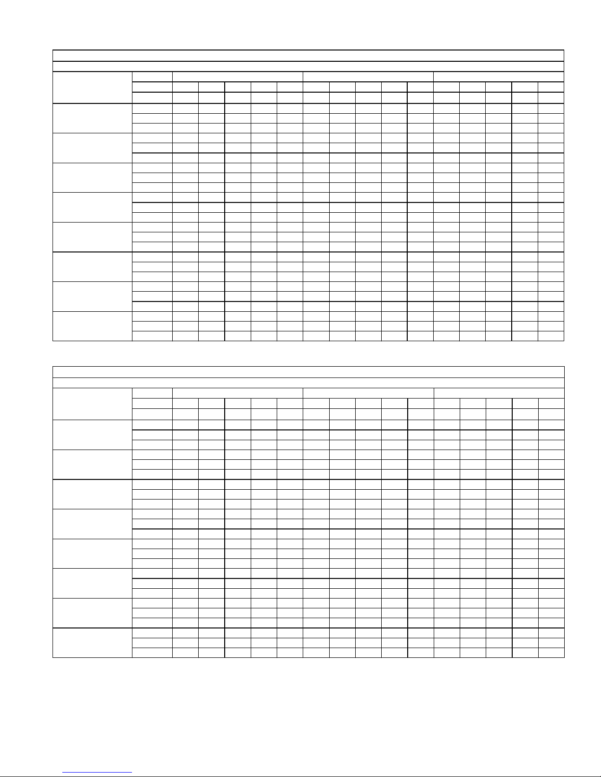
COOLING PERFORMANCE DATA - 4 TON (LOW SPEED)
PACKAGED UNIT MODEL NO. PCE6B48
CONDENSER
ENTERING AIR
TEMPERATURE
55 / 45
65 / 55
75 / 63
85 / 69
95 / 75
105 / 83
115 / 89
125 / 95
ID CFM 900 1100 1300
IDDB 80 80 75 80 80 80 80 75 80 80 80 80 75 80 80
IDWB 57 62 62 67 72 57 62 62 67 72 57 62 62 67 72
T.C. 34.3 37.4 36.3 41.1 45.6 37.5 39.7 38.7 43.6 48.0 40.6 42.1 41.1 46.2 50.3
S.C. 32.3 28.7 24.7 24.9 20.0 34.8 32.1 27.2 27.2 21.8 37.4 35.5 29.8 29.6 23.6
K.W. 1.67 1.64 1.65 1.63 1.49 1.63 1.61 1.62 1.59 1.52 1.58 1.58 1.58 1.56 1.55
T.C. 32.4 34.5 34.1 38.7 43.8 35.2 36.8 36.6 41.0 46.2 38.1 39.1 39.1 43.3 48.7
S.C. 30.4 27.4 21.0 23.5 18.9 32.8 30.2 23.2 25.8 20.7 35.1 33.0 25.3 28.1 22.5
K.W. 1.86 1.83 1.85 1.79 1.73 1.85 1.83 1.84 1.82 1.76 1.84 1.82 1.83 1.84 1.79
T.C. 30.4 31.6 32.0 36.3 42.0 33.0 33.9 34.5 38.4 44.5 35.5 36.2 37.1 40.4 47.0
S.C. 28.6 26.0 17.4 22.1 17.8 30.7 28.2 19.1 24.4 19.6 32.9 30.5 20.8 26.6 21.5
K.W. 2.05 2.03 2.04 1.96 1.97 2.07 2.05 2.06 2.05 2.01 2.10 2.06 2.08 2.13 2.04
T.C. 27.3 29.1 28.2 34.0 39.1 29.4 31.1 29.9 35.7 41.2 31.4 33.0 31.6 37.5 43.4
S.C. 26.2 23.9 18.1 20.8 16.5 28.0 26.6 19.9 22.9 18.0 29.9 29.3 21.8 25.1 19.5
K.W. 2.39 2.36 2.43 2.37 2.30 2.41 2.38 2.42 2.39 2.33 2.43 2.41 2.41 2.42 2.36
T.C. 24.2 26.7 24.5 31.6 36.1 25.8 28.2 25.3 33.1 37.9 27.4 29.7 26.2 34.6 39.7
S.C. 23.8 21.8 18.8 19.4 15.1 25.4 25.0 20.8 21.5 16.4 26.9 28.2 22.8 23.6 17.6
K.W. 2.72 2.68 2.82 2.78 2.63 2.74 2.72 2.78 2.74 2.65 2.76 2.75 2.74 2.70 2.68
T.C. 21.9 23.6 20.8 27.3 32.6 23.1 24.7 21.1 29.0 33.9 24.2 25.7 21.3 30.6 35.3
S.C. 21.5 20.3 17.0 19.1 13.6 22.7 22.5 18.0 21.1 14.7 23.9 24.6 19.0 23.2 15.7
K.W. 3.15 3.16 3.22 3.16 3.06 3.17 3.17 3.20 3.14 3.09 3.18 3.18 3.18 3.12 3.12
T.C. 19.6 20.6 17.1 23.2 29.2 20.4 21.2 16.9 25.0 30.1 21.2 21.8 16.6 26.8 31.1
S.C. 19.3 18.8 15.1 18.8 12.2 20.1 20.0 15.3 20.8 13.0 20.9 21.1 15.4 22.7 13.9
K.W. 3.56 3.63 3.60 3.53 3.47 3.58 3.61 3.60 3.53 3.51 3.59 3.60 3.60 3.53 3.54
T.C. 17.3 17.6 13.5 19.1 25.7 17.7 17.8 12.7 21.0 26.3 18.2 17.9 11.9 22.9 26.8
S.C. 17.0 17.4 13.3 18.6 10.7 17.4 17.5 12.5 20.4 11.4 17.9 17.6 11.8 22.3 12.1
K.W. 3.98 4.10 3.98 3.91 3.89 3.99 4.05 4.00 3.92 3.93 4.00 4.01 4.02 3.93 3.97
5324339-YTG-D-1117
COOLING PERFORMANCE DATA - 4 TON (HIGH SPEED)
PACKAGED UNIT MODEL NO. PCE6B48
CONDENSER
ENTERING AIR
TEMPERATURE
55 / 45
65 / 55
75 / 63
85 / 69
95 / 75
105 / 83
115 / 89
125 / 95
ID CFM 1400 1600 1800
IDDB 80 80 75 80 80 80 80 75 80 80 80 80 75 80 80
IDWB 57 62 62 67 72 57 62 62 67 72 57 62 62 67 72
T.C. 46.5 54.3 55.5 56.6 59.6 47.9 54.3 55.6 56.8 59.9 49.2 54.3 55.6 56.9 60.1
S.C. 45.7 41.3 35.4 35.0 27.8 47.2 43.3 36.8 35.0 28.0 48.7 45.2 38.2 35.0 28.1
K.W. 2.66 2.72 2.72 2.93 2.75 2.76 2.80 2.80 2.92 2.82 2.86 2.88 2.87 2.90 2.89
T.C. 43.8 51.2 52.2 54.8 58.3 44.9 51.7 52.7 54.8 58.7 46.1 52.1 53.3 54.9 59.1
S.C. 43.3 40.2 34.1 33.8 27.0 44.3 35.9 37.0 34.7 31.7 45.3 31.7 40.0 35.5 36.5
K.W. 2.93 3.06 2.98 3.11 3.13 3.03 3.06 3.06 3.15 3.16 3.13 3.06 3.14 3.19 3.20
T.C. 41.1 48.2 48.8 52.9 56.9 42.0 49.1 49.9 52.9 57.5 43.0 49.9 51.0 52.8 58.1
S.C. 41.0 39.1 32.9 32.6 26.1 41.5 28.6 37.3 34.3 35.5 41.9 18.2 41.8 36.0 44.9
K.W. 3.19 3.39 3.24 3.29 3.51 3.29 3.32 3.33 3.38 3.51 3.39 3.25 3.41 3.47 3.50
T.C. 40.3 45.2 46.3 49.4 53.8 40.1 45.6 46.8 49.2 54.0 39.9 46.1 47.2 48.9 54.2
S.C. 39.8 37.3 31.1 31.2 24.6 39.4 33.1 34.1 32.8 29.8 39.1 28.9 37.2 34.4 34.9
K.W. 3.55 3.66 3.58 3.72 3.77 3.64 3.67 3.66 3.77 3.81 3.74 3.67 3.75 3.81 3.85
T.C. 39.4 42.2 43.8 45.9 50.7 38.1 42.2 43.6 45.5 50.5 36.8 42.3 43.4 45.1 50.3
S.C. 38.6 35.5 29.3 29.7 23.1 37.4 37.6 30.9 31.2 24.1 36.2 39.7 32.6 32.7 25.0
K.W. 3.91 3.93 3.92 4.15 4.03 4.00 4.01 4.00 4.15 4.11 4.09 4.09 4.08 4.15 4.19
T.C. 34.6 37.5 39.1 41.7 46.5 34.0 37.9 39.0 41.3 46.1 33.4 38.3 38.9 40.9 45.7
S.C. 34.0 33.1 27.4 27.8 21.2 33.4 34.8 26.2 29.3 22.0 32.9 36.5 25.1 30.9 22.9
K.W. 4.42 4.49 4.43 4.65 4.58 4.51 4.54 4.47 4.65 4.63 4.59 4.60 4.52 4.65 4.68
T.C. 29.9 33.0 34.6 37.7 42.4 30.0 33.8 34.5 37.2 41.8 30.1 34.5 34.5 36.8 41.2
S.C. 29.5 30.7 25.5 26.0 19.3 29.6 32.1 21.7 27.6 20.1 29.8 33.5 17.9 29.1 20.8
K.W. 4.91 5.03 4.92 5.14 5.12 5.00 5.06 4.94 5.13 5.14 5.09 5.09 4.95 5.13 5.17
T.C. 25.2 28.4 30.1 33.6 38.2 26.0 29.6 30.1 33.2 37.5 26.8 30.7 30.1 32.7 36.7
S.C. 25.0 28.4 23.6 24.2 17.5 25.8 29.4 17.1 25.8 18.1 26.6 30.4 10.6 27.3 18.8
K.W. 5.41 5.58 5.41 5.62 5.66 5.50 5.58 5.40 5.62 5.66 5.58 5.58 5.39 5.62 5.65
Johnson Controls Unitary Products 9
Page 10
5324339-YTG-D-1117
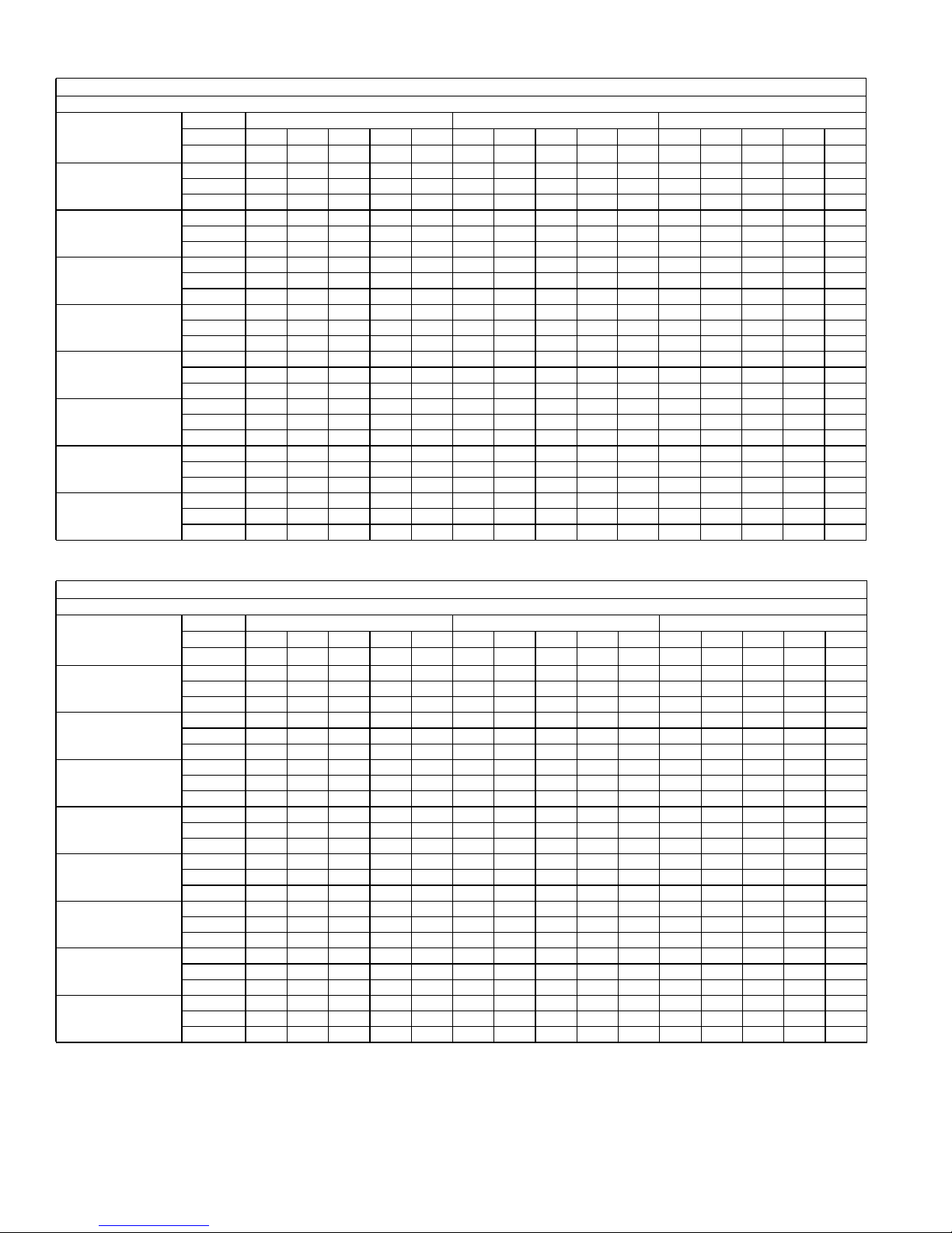
COOLING PERFORMANCE DATA - 5 TON (LOW SPEED)
PACKAGED UNIT MODEL NO. PCE6B60
CONDENSER
ENTERING AIR
TEMPERATURE
55 / 45
65 / 55
75 / 63
85 / 69
95 / 75
105 / 83
115 / 89
125 / 95
ID CFM 1100 1300 1500
IDDB 80 80 75 80 80 80 80 75 80 80 80 80 75 80 80
IDWB 57 62 62 67 72 57 62 62 67 72 57 62 62 67 72
T.C. 44.6 51.1 50.5 55.7 59.9 47.1 53.0 51.7 57.4 61.8 49.5 54.9 53.0 59.2 63.8
S.C. 44.6 43.1 36.8 36.5 30.0 47.1 47.5 40.0 39.4 31.6 49.5 51.8 43.3 42.4 33.3
K.W. 1.77 1.77 1.77 1.74 1.90 1.87 1.87 1.88 1.84 1.92 1.98 1.98 1.99 1.94 1.94
T.C. 42.1 47.6 46.8 52.1 57.3 44.3 49.4 48.4 53.9 59.6 46.6 51.2 50.1 55.7 61.9
S.C. 42.1 41.4 35.0 34.9 28.5 44.3 45.6 38.1 37.8 30.2 46.6 49.9 41.2 40.8 31.9
K.W. 2.05 2.05 2.14 2.11 2.08 2.15 2.15 2.20 2.16 2.14 2.25 2.24 2.25 2.22 2.20
T.C. 39.6 44.2 43.1 48.5 54.8 41.6 45.8 45.1 50.3 57.4 43.7 47.4 47.1 52.1 60.1
S.C. 39.6 39.6 33.3 33.3 26.9 41.6 43.8 36.2 36.2 28.7 43.7 47.4 39.1 39.2 30.4
K.W. 2.34 2.33 2.51 2.48 2.26 2.43 2.42 2.51 2.48 2.36 2.52 2.51 2.52 2.49 2.45
T.C. 36.5 40.6 39.8 44.8 50.8 38.3 41.8 41.5 46.3 53.0 40.1 43.0 43.2 47.9 55.1
S.C. 36.5 37.6 31.4 31.4 25.1 38.3 40.9 34.2 34.3 26.8 40.1 43.0 37.0 37.2 28.6
K.W. 2.69 2.67 2.87 2.74 2.61 2.78 2.77 2.87 2.79 2.71 2.87 2.88 2.88 2.84 2.81
T.C. 33.4 37.0 36.4 41.0 46.9 35.0 37.8 37.8 42.3 48.5 36.5 38.6 39.3 43.6 50.2
S.C. 33.4 35.5 29.5 29.5 23.2 35.0 37.8 32.2 32.3 25.0 36.5 38.6 34.9 35.1 26.7
K.W. 3.04 3.02 3.23 3.00 2.96 3.13 3.13 3.23 3.10 3.07 3.22 3.25 3.24 3.20 3.17
T.C. 30.0 34.0 32.7 36.5 42.1 31.3 34.3 33.6 37.3 43.3 32.7 34.6 34.5 38.1 44.6
S.C. 30.0 32.8 27.2 27.4 21.2 31.3 34.3 29.6 30.1 22.7 32.7 34.6 32.0 32.9 24.3
K.W. 3.56 3.48 3.62 3.46 3.43 3.62 3.59 3.66 3.56 3.53 3.69 3.70 3.70 3.66 3.63
T.C. 26.7 31.1 29.0 32.1 37.4 27.8 30.9 29.4 32.5 38.3 28.9 30.6 29.9 32.8 39.1
S.C. 26.7 30.3 25.0 25.4 19.2 27.8 30.9 27.1 28.0 20.6 28.9 30.6 29.2 30.7 21.9
K.W. 4.07 3.93 4.00 3.91 3.87 4.10 4.03 4.07 4.01 3.98 4.13 4.13 4.14 4.11 4.09
T.C. 23.4 28.3 25.3 27.7 32.7 24.3 27.5 25.3 27.6 33.2 25.1 26.7 25.2 27.5 33.7
S.C. 23.4 27.7 22.8 23.4 17.2 24.3 27.5 24.6 25.9 18.4 25.1 26.7 25.2 27.5 19.6
K.W. 4.57 4.38 4.39 4.35 4.32 4.58 4.47 4.49 4.46 4.43 4.58 4.57 4.59 4.56 4.54
COOLING PERFORMANCE DATA - 5 TON (HIGH SPEED)
PACKAGED UNIT MODEL NO. PCE6B60
CONDENSER
ENTERING AIR
TEMPERATURE
55 / 45
65 / 55
75 / 63
85 / 69
95 / 75
105 / 83
115 / 89
125 / 95
ID CFM 1600 1800 2000
IDDB 80 80 75 80 80 80 80 75 80 80 80 80 75 80 80
IDWB 57 62 62 67 72 57 62 62 67 72 57 62 62 67 72
T.C. 59.2 68.9 66.5 71.8 77.1 61.3 70.6 67.6 73.5 77.7 63.5 72.3 68.8 75.1 78.3
S.C. 59.2 55.8 47.0 46.7 37.2 61.3 59.6 49.6 49.1 38.2 63.5 63.4 52.2 51.5 39.1
K.W. 2.80 2.86 2.87 3.21 2.93 3.03 3.08 3.08 3.28 3.14 3.26 3.30 3.30 3.34 3.35
T.C. 54.3 64.1 61.7 68.4 74.2 55.7 66.1 63.2 69.9 75.5 57.2 68.1 64.7 71.3 76.9
S.C. 54.3 53.9 45.4 44.9 35.7 55.7 42.9 51.1 47.3 46.7 57.2 31.9 56.8 49.8 57.8
K.W. 3.07 3.25 3.13 3.34 3.37 3.30 3.34 3.35 3.48 3.51 3.53 3.42 3.56 3.62 3.66
T.C. 49.3 59.2 57.0 65.1 71.3 50.1 61.6 58.8 66.3 73.4 50.9 64.0 60.6 67.4 75.4
S.C. 49.3 52.0 43.7 43.0 34.2 50.1 26.2 52.5 45.5 55.3 50.9 0.3 60.6 48.0 75.4
K.W. 3.33 3.65 3.39 3.47 3.81 3.57 3.60 3.61 3.68 3.89 3.80 3.55 3.83 3.90 3.97
T.C. 48.7 55.4 53.9 60.5 67.1 47.8 57.3 55.3 61.5 68.6 46.8 59.2 56.8 62.4 70.2
S.C. 48.7 49.6 41.4 41.0 32.2 47.8 38.2 47.0 43.3 43.3 46.8 26.7 52.7 45.7 54.5
K.W. 3.71 3.87 3.74 3.95 4.02 3.94 3.96 3.96 4.10 4.17 4.16 4.04 4.17 4.25 4.32
T.C. 48.0 51.6 50.7 55.9 62.8 45.4 53.0 51.8 56.7 63.9 42.8 54.3 53.0 57.4 64.9
S.C. 48.0 47.2 39.1 39.1 30.3 45.4 50.1 41.5 41.2 31.4 42.8 53.0 43.9 43.3 32.6
K.W. 4.09 4.10 4.09 4.44 4.23 4.30 4.31 4.30 4.52 4.44 4.52 4.53 4.51 4.60 4.66
T.C. 42.5 46.6 45.9 50.9 57.9 40.7 48.1 47.1 51.6 58.7 38.9 49.5 48.3 52.3 59.6
S.C. 42.5 43.9 36.8 36.9 28.2 40.7 46.3 33.0 39.0 29.3 38.9 48.7 29.1 41.1 30.4
K.W. 4.60 4.71 4.61 4.96 4.84 4.82 4.87 4.77 5.04 5.00 5.03 5.04 4.92 5.11 5.17
T.C. 37.0 41.8 41.3 46.0 53.1 36.1 43.4 42.5 46.7 53.8 35.1 44.9 43.8 47.4 54.4
S.C. 37.0 40.7 34.7 34.7 26.2 36.1 42.6 24.7 36.9 27.2 35.1 44.5 14.7 39.0 28.2
K.W. 5.10 5.29 5.12 5.46 5.43 5.32 5.42 5.23 5.54 5.54 5.54 5.54 5.33 5.61 5.66
T.C. 31.6 37.0 36.6 41.1 48.2 31.5 38.6 37.9 41.8 48.8 31.4 40.2 39.3 42.5 49.3
S.C. 31.6 37.0 32.5 32.6 24.2 31.5 38.6 16.4 34.7 25.1 31.4 40.2 0.3 36.8 26.1
K.W. 5.60 5.88 5.63 5.96 6.01 5.82 5.96 5.68 6.04 6.09 6.04 6.04 5.74 6.11 6.16
10 Johnson Controls Unitary Products
Page 11
+,*+92/7$*(
23(1,1*´
+,*+92/7$*(
23(1,1*´
&2035(6625
$&&(663$1(/
5324339-YTG-D-1117
&2,/*8$5'
&
+($76(&7,21
$&&(663$1(/
&21'(16$7(
'5$,1
%/2:(5
$&&(66
3$1(/
$
&21752/+($7
$&&(663$1(/
%
/2:92/7$*(23(1,1*´
$
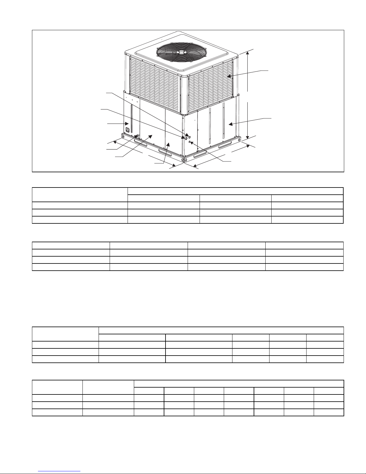
UNIT DIMENSIONS & ACCESS LOCATIONS
Model
ABC
PCE6B36 51-1/4 45-3/4 49
PCE6B48 51-1/4 45-3/4 53
PCE6B60 51-1/4 45-3/4 55
UNIT CLEARANCES
Direction Distance (in.) Direction Distance (in.)
1
Top
36 Power Entry (Right Side) 36
Side Opposite Ducts 36 Left Side 24
Duct Panel 0 Bottom
NOTES:
1. Minimum Clearance of 1inch all sides of supply air duct for the first 3 feet of duct for 20 & 25 kW., zero inches thereafter. For all other heaters, zero inch clearance
all sides for entire length of duct.
2. Units must be installed outdoors. Overhanging structures or shrubs should not obscure outdoor air discharge outlet.
3. Units may be installed on combustible floors made from wood or class A, B or C roof covering materials.
Note: For units applied with a roof curb, the minimum clearance may be reduced from 1 inch to 1/2 inch between combustible roof curb material and this supply air
duct.
Dimensions - in inches
2,3
1
INDOOR BLOWER SPECIFICATIONS
Model
PCE6B36 1/2 Variable 0.8 1.0 48
PCE6B48 1 Variable 0.8 1.0 48
PCE6B60 1 Variable 0.8 1.0 48
SOUND PERFORMANCE
Model
(Tons)
Sound Rating
dB (A)
PCE6B36 74 58.5 61.8 65.4 66.5 60.7 54.8 49.8
PCE6B48 74 63.5 63.9 62.3 65 64 54.1 46.6
PCE6B60 76 72.3 65.0 63.9 64 60 55.5 49.0
NOTES:
1. Rated in accordance with AHRI Standard 270.
Johnson Controls Unitary Products 11
1
Motor
HP RPM EFF. SF Frame
Octave Band Centerline Frequency (Hz)
125 250 500 1000 2000 4000 8000
Page 12
5324339-YTG-D-1117
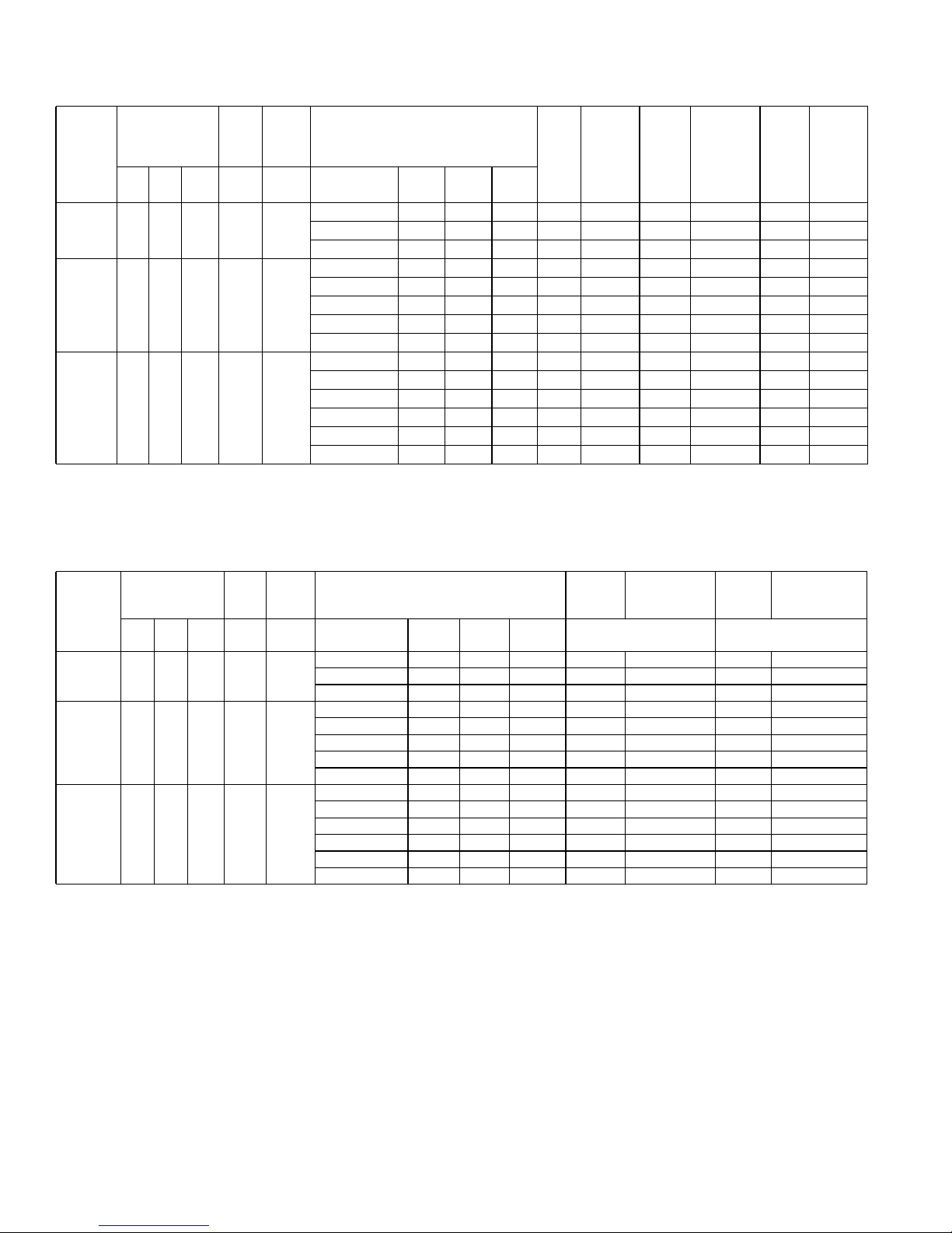
ELECTRICAL DATA - 460-3-60 - SINGLE SOURCE POWER
Model
Compressor
OD
Fan
Motor
ID
Blower
Motor Electric Heat Option
4
Heater
kW Stages
Heater
Amps
MCA
(Total
Unit)
Fuse2 or
Breaker
1
Size3
(Total
Unit)
Max
MCA1
(Unit
Less
Heater)
Max
Fuse2 or
Breaker
Size3
(Unit Less
Heater)
MCA1
Unit
(Heater
Only)
Max
Fuse2 or
Breaker
Size3
(Heater
Only)RLA LRA MCC FLA FLA Heater Kit
none -- -- -- 9.9 15 9.9 15 -- --
PCE6B36 5.7 38.0 8.9 0.87 1.9
6HK06501046 8.8 1 11 13.4 15 9.9 15 13.8 15
6HK06501546 13.2 1 16.6 18.9 20 9.9 15 20.7 25
none -- -- -- 12.2 15 12.2 15 -- --
6HK06501046 8.8 1 11 15.2 20 12.2 15 13.8 15
PCE6B48 6.4 41.0 10.0 0.87 3.3
6HK06501546 13.2 1 16.6 20.7 25 12.2 15 20.7 25
6HK06501846 15.9 1 20 24.1 25 12.2 15 24.9 25
6HK06502046 17.6 1 22.1 26.2 30 12.2 15 27.6 30
none -- -- -- 13.7 20 13.7 20 -- --
6HK06501046 8.8 1 11 15 20 13.7 20 13.8 15
PCE6B60 7.6 52.0 11.9 0.87 3.3
6HK06501546 13.2 1 16.6 20.5 25 13.7 20 20.7 25
6HK06501846 15.9 1 20 23.9 25 13.7 20 24.9 25
6HK06502046 17.6 1 22.1 26 30 13.7 20 27.6 30
6HK06502546 22 1 27.6 31.5 35 13.7 20 34.5 35
NOTES: Single-source power MCA and MOP requirements are given here for reference if the unit is to be installed with a field-installed single-point power modification.
1. MCA = Minimum Circuit Ampacity.
2. Maximum Over Current Protection per standard UL 1995.
3. Fuse or HACR circuit breaker to be field installed.
4. Single Point Connection Required.
ELECTRICAL DA TA FOR - 460-3-60 MULTI SOURCE POWER
OD
Compressor
Model
Fan
Motor
Blower
Motor
RLA LRA MCC FLA FLA Heater Kit
PCE6A36 5.7 38.0 8.9 0.87 1.9
PCE6B48 6.4 41.0 10.0 0.87 3.3
PCE6B60 7.6 52.0 11.9 0.87 3.3
Electric Heat Option
Heater
kW
Stages
Heater
Amps
none -- -- -- 9.9 15 -- -6HK06501046 8.8 1 11.0 9.9 15 13.8 15
6HK06501546 13.2 1 16.6 9.9 15 20.7 25
none -- -- -- 12.2 15 -- -6HK06501046 8.8 1 11.0 12.2 15 13.8 15
6HK06501546 13.2 1 16.6 12.2 15 20.7 25
6HK06501846 15.9 1 20.0 12.2 15 24.9 25
6HK06502046 17.6 1 22.1 12.2 15 27.6 30
none -- -- -- 13.7 20 -- -6HK06501046 8.8 1 11.0 13.7 20 13.8 15
6HK06501546 13.2 1 16.6 13.7 20 20.7 25
6HK06501846 15.9 1 20.0 13.7 20 24.9 25
6HK06502046 17.6 1 22.1 13.7 20 27.6 30
6HK06502546 22.0 1 27.6 13.7 20 34.5 35
MCA
Amps
Max Fuse or
Breaker Size
CIRCUIT #1
Unit Minus Heaters
MCA
Amps
Max Fuse or
Breaker Size
CIRCUIT #2
Heaters
12 Johnson Controls Unitary Products
Page 13
5324339-YTG-D-1117
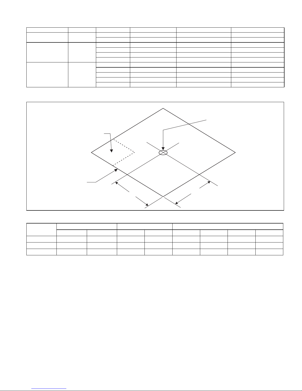
SINGLE POINT WIRING KIT PART NUMBERS
Unit Model Number Voltage Heater Kit Single-Point Wiring Kit Unit Fuse Size (Amps) Heater Fuse Size (Amps)
PCE6B3641 460-3-60
PCE6B4841 460-3-60
PCE6B6041 460-3-60
COMPRESSOR
6HK06501046 S1-2SPWK036 15 15
6HK06501546 S1-2SPWK036 15 25
6HK06501046 S1-2SPWK036 15 15
6HK06501546 S1-2SPWK036 15 25
6HK06501846 S1-2SPWK036 15 25
6HK06502046 S1-2SPWK036 15 30
6HK06501046 S1-2SPWK036 20 15
6HK06501546 S1-2SPWK036 20 25
6HK06501846 S1-2SPWK036 20 25
6HK06502046 S1-2SPWK036 20 30
6HK06502546 S1-2SPWK037 20 35
"D"
CENTER OF
GRAVITY
"A"
FRONT
OF UNIT
X
"B"
Y
WEIGHTS AND DIMENSIONS
Model Weight (lbs.) Center of Gravity 4 Point Load Location (lbs.)
Shipping Operating X Y ABCD
PCE6B36
PCE6B48
PCE6B60
466 461 32 13 167 131 130 38
488 483 30 19 158 125 130 75
505 500 30 20 157 134 140 74
"C"
A0295-001-TG
Johnson Controls Unitary Products 13
Page 14
5324339-YTG-D-1117
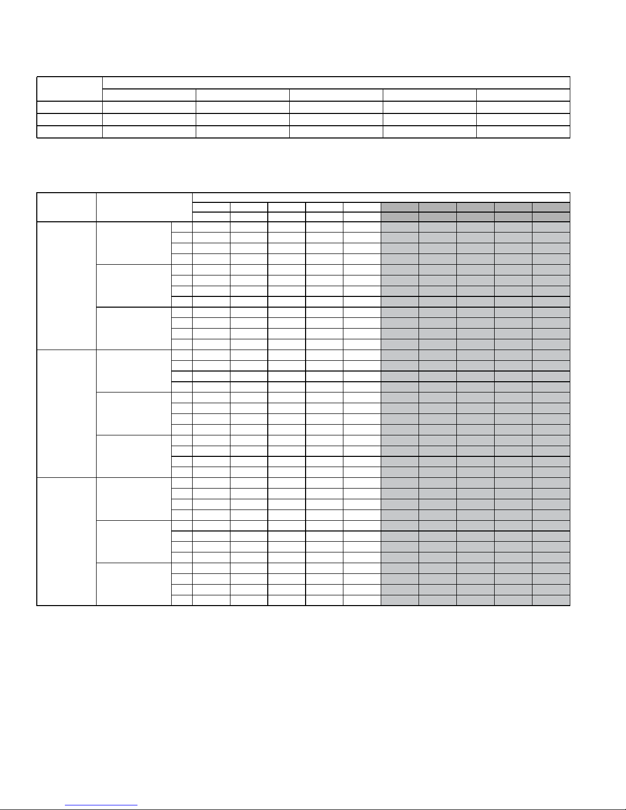
RECOMMENDED BLOWER SPEED FOR ELECTRIC HEAT
Model
10 15 18 20 25
Heater kW
PCE6B36 C (ML) A (HI) -- -- -PCE6B48 D (LO) C (ML) B (MH) A (HI) -PCE6B60 D (LO) D (LO) C (ML) B (MH) A (HI)
NOTE: The recommended HEAT speed selections above will give approximately a 45 degree temperature rise at 0.3" static with 460V power supply. If lower or higher
heating airflow is desired, or if duct static or voltage are different than specified, other speed taps may be used.
AIRFLOW PERFORMANCE - SIDE DUCT APPLICATION
Model Jumper Position
0.1 0.2 0.3 0.4 0.5 0.6 0.7 0.8 0.9 1.0
SCFM SCFM SCFM SCFM SCFM
A 1621 1531 1454 1371 1299
High Cool
B 1507 1418 1339 1268 1200
C 1410 1288 1209 1132 1054
D 1224 1137 1052 978 902
A 1060 964 879 795 706
36
Low Cool
B 1017 919 830 742 650
C 974 875 780 688 595
D 813 721 617 509 404
A 1264 1179 1092 1017 942
Heat
B 1147 1056 972 895 815 735 657 578 511 450
C 1003 904 813 724 632
D 902 802 700 602 504
A 1893 1845 1804 1764 1717
High Cool
B 1785 1737 1694 1650 1597
C 1703 1649 1595 1546 1491
D 1654 1596 1535 1483 1427
A 1304 1225 1152 1072 998
48
Low Cool
B 1265 1183 1109 1026 950
C 1200 1116 1039 952 874 757 707 652 599 512
D 1304 1225 1152 1072 998
A 1423 1351 1281 1211 1143
Heat
B 1304 1225 1152 1072 998
C 1125 1039 957 870 791
D 1000 912 820 733 652
A 2305 2255 2215 2164 2103
High Cool
B 2186 2144 2101 2059 2003
C 2007 1963 1919 1873 1828
D 1935 1887 1840 1788 1754
A 1675 1627 1566 1512 1473 1423 1374 1324 1278 1234
60
Low Cool
B 1523 1463 1405 1350 1302
C 1369 1307 1251 1196 1141
D 1413 1352 1295 1240 1187
A 1762 1724 1661 1608 1574
Heat
B 1479 1418 1361 1306 1256
C 1369 1307 1251 1196 1141
D 1209 1147 1084 1022 957
NOTES:
1. Airflow tested with dry coil conditions, without air filters, at 460 volts
2. Applications above 0.8" w.c. external static pressure are not recommended.
3. Brushless DC high efficiency enhanced ECM blower motor used for all indoor blower assemblies.
4. Minimal variations in airflow performance data results from using downflow duct applications. Data above may be used in those cases.
5. Heating applications tested at 0.50" w.c. esp, and cooling applications tested at 0.30" w.c.esp per standards.
External Static Pressure (Inches WC)
SCFM SCFM SCFM SCFM SCFM
1223 1138 1039 966 869
1130 1059 981 911 837
982 904 831 755 691
824 748 682 611 549
623 538 459 397 331
570 487 415 344 276
517 436 371 291 222
323 237 171 81 81
865 787 735 662 598
552 470 400 327 258
429 348 292 201 201
1672 1625 1576 1528 1473
1547 1501 1452 1392 1335
1436 1385 1327 1264 1200
1370 1315 1252 1187 1118
893 842 785 731 648
839 789 733 681 596
893 842 785 731 648
1056 1002 941 883 804
893 842 785 731 648
672 623 564 507 416
529 481 418 354 255
2074 2024 1965 1910 1867
1956 1930 1886 1837 1796
1781 1731 1693 1646 1606
1702 1645 1609 1560 1519
1248 1196 1143 1089 1044
1082 1024 964 907 849
1130 1073 1015 959 905
1526 1478 1429 1390 1341
1201 1147 1092 1037 989
1082 1024 964 907 849
897 835 777 722 669
14 Johnson Controls Unitary Products
Page 15
5324339-YTG-D-1117
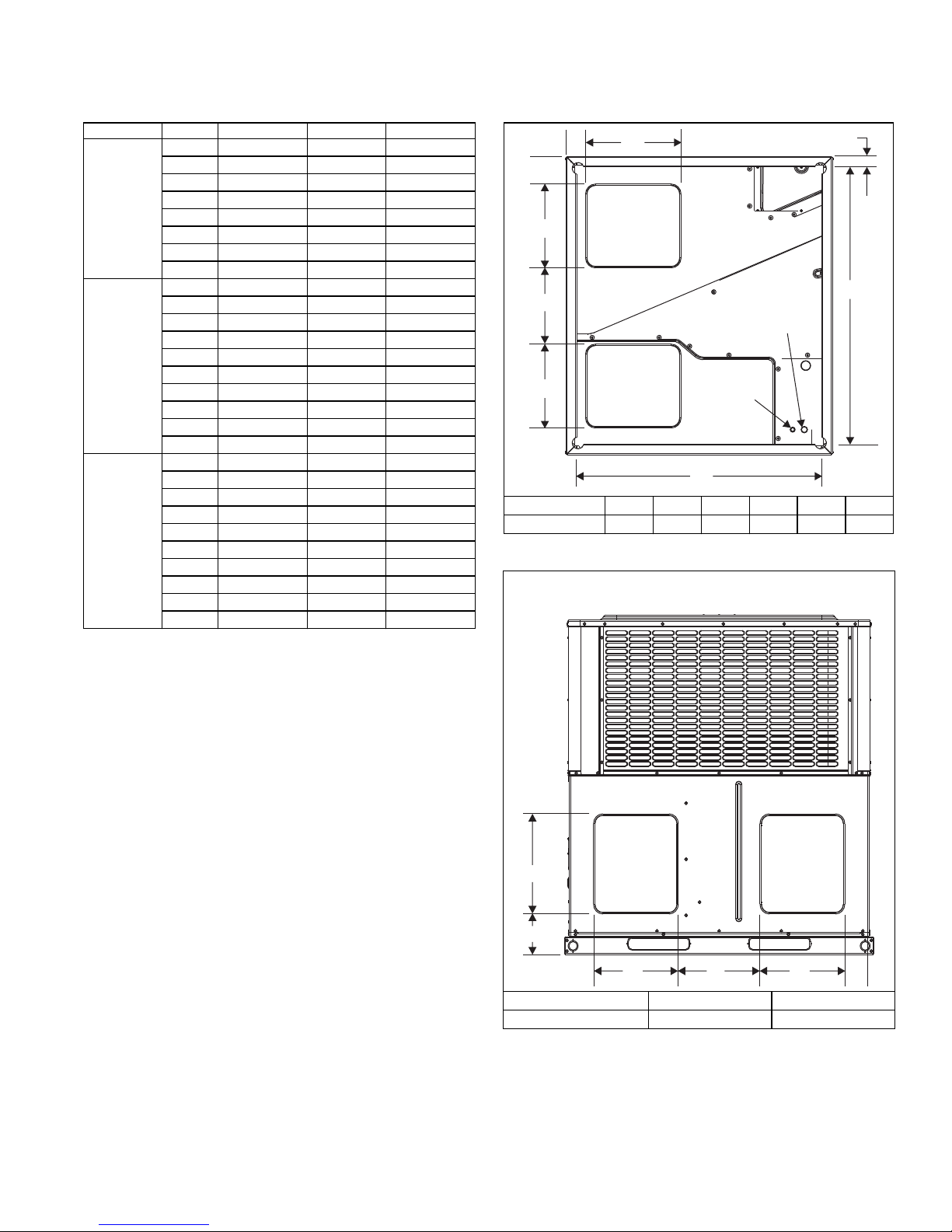
ADDITIONAL ST ATIC RESISTANCE
Size (Tons) CFM Wet Indoor Coil Economizer
700 0.01 0.00 0.04
800 0.02 0.01 0.06
900 0.03 0.01 0.08
36 (3.0)
1000 0.04 0.01 0.10
1100 0.05 0.01 0.13
1200 0.06 0.02 0.16
1300 0.07 0.03 0.17
1400 0.08 0.04 0.18
1100 0.02 0.02 0.04
1200 0.03 0.02 0.04
1300 0.04 0.02 0.05
1400 0.05 0.03 0.05
48 (4.0)
1500 0.06 0.04 0.06
1600 0.07 0.04 0.07
1700 0.07 0.04 0.08
1800 0.08 0.04 0.09
1900 0.09 0.05 0.10
2000 0.09 0.05 0.11
1100 0.02 0.02 0.04
1200 0.03 0.02 0.04
1300 0.04 0.02 0.05
1400 0.05 0.03 0.05
60 (5.0)
1500 0.06 0.04 0.06
1600 0.07 0.04 0.07
1700 0.07 0.04 0.08
1800 0.08 0.04 0.09
1900 0.09 0.05 0.10
2000 0.09 0.05 0.11
NOTES:
1. The pressure drop through the economizer is greater for 100% outdoor air
than for 100% return air. If the resistance of the return air duct is less than
0.25 IWG, the unit will deliver less CFM during full economizer operation.
Filter pressure drop based on standard filter media tested at velocities not
to exceed 300 ft/min.
1
Filter/Frame Kit
BOTTOM DUCT DIMENSIONS (Inches)
'
&
$
%
$
5(7851
$,5'8&7
6833/<
$,5'8&7
+2/(
Model ABCDEF
36, 48, 60 14 13.5 5 3.5 47.5 42
9,(:/22.,1*83
$7%277202)81,7
´IRUKLJKYROWDJH
+2/(´IRU
ORZYROWDJH
)
REAR DUCT DIMENSIONS (Inches)
127(6HH)LJXUHWLWOHG³8QLW'LPHQVLRQV´IRUVLGHKROHVL]HVRI
HOHFWULFDOOLQHV
(
$
Johnson Controls Unitary Products 15
6833/<
$
$,5'8&7
$
%
Model A B
36, 48, 60 13.6 14
5(7851
$,5'8&7
$
Page 16
5324339-YTG-D-1117
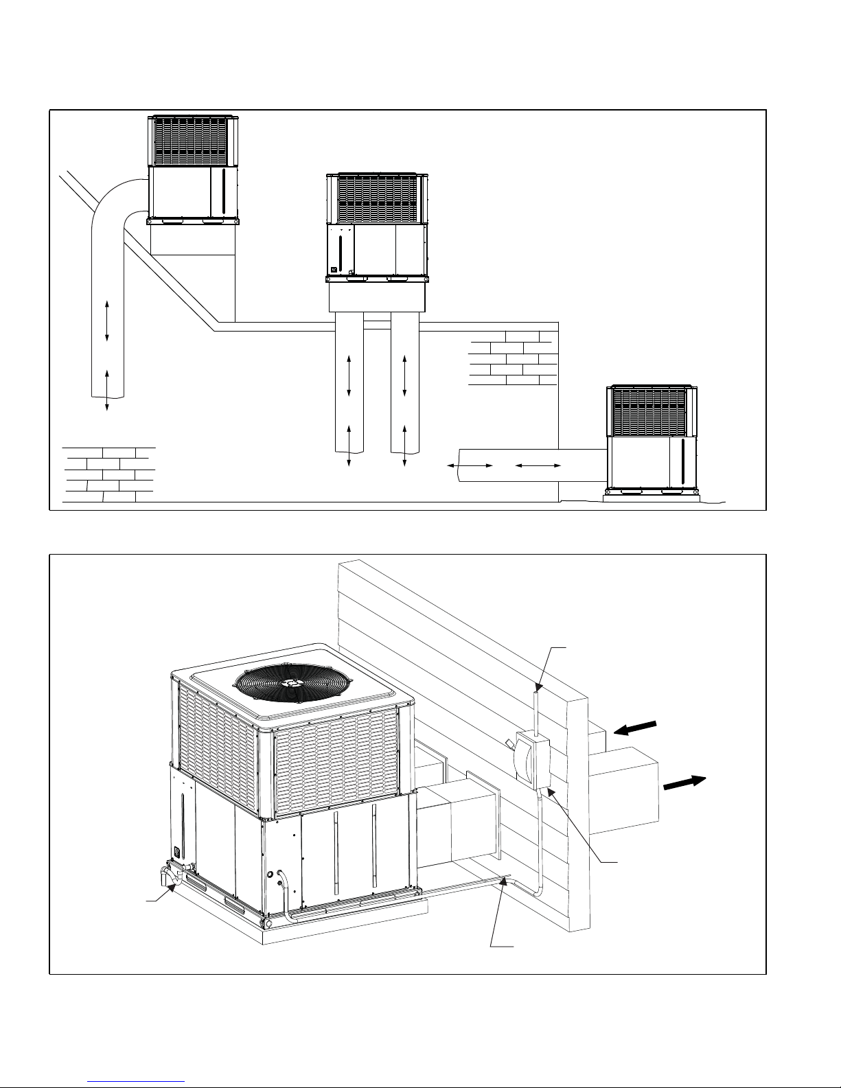
UNIT TYPICAL DUCT APPLICATIONS
ROOF CURB
INSTALLATION
REAR DUCT
ROOF CURB
INSTALLATION
BOTTOM DUCT
SLAB ON
GROUND
INSTALLATION
A0324-001
UNIT TYPICAL SLAB ON GROUND INSTALLATION
CONDENSATE
DRAIN
TO POWER SUPPLY
FIELD-SUPPLIED
DISCONNECT
SWITCH
RETURN
AIR DUCT
SUPPLY
AIR DUCT
16 Johnson Controls Unitary Products
CONTROL WIRING TO
INDOOR THERMOSTAT
A0390-001
Page 17
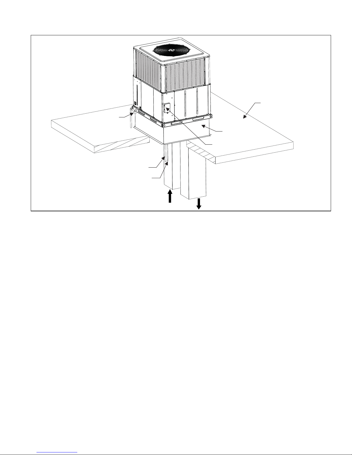
UNIT TYPICAL ROOF CURB INSTALLATION
CONDENSATE
DRAIN
TO POWER SUPPLY
CONTROL WIRING TO
INDOOR THERMOSTAT
ROOF CURB
FIELD-SUPPLIED
DISCONNECT
SWITCH
5324339-YTG-D-1117
ROOF
RETURN
AIR DUCT
SUPPLY
AIR DUCT
A0389-001
Johnson Controls Unitary Products 17
Page 18

NOTES
Subject to change without notice. Published in U.S.A. 5324339-YTG-D-1117
Copyright © 2017 by Johnson Controls, Inc. All rights reserved. Supersedes: 5324339-YTG-C-0817
York International Corp.
5005 York Drive
Norman, OK 73069
 Loading...