

Page 1
INSTALLATION MANUAL
HIGH EFFICIENCY
TUBULAR HEAT EXCHANGER SERIES
MODELS: PC9*UP, FC9C*UP, FL9C*UP
(Modulating Upflow with ECM Motor)
60 - 120 MBH INPUT
(17.6 - 35.2 KW) INPUT
LIST OF SECTIONS
FURNACE DESCRIPTION . . . . . . . . . . . . . . . . . . . . . . . . . . . . . . . . . . . . 1
SAFETY . . . . . . . . . . . . . . . . . . . . . . . . . . . . . . . . . . . . . . . . . . . . . . . . . . . 1
DUCTWORK . . . . . . . . . . . . . . . . . . . . . . . . . . . . . . . . . . . . . . . . . . . . . . . 4
FILTERS . . . . . . . . . . . . . . . . . . . . . . . . . . . . . . . . . . . . . . . . . . . . . . . . . . . 6
GAS PIPING . . . . . . . . . . . . . . . . . . . . . . . . . . . . . . . . . . . . . . . . . . . . . . . . 7
ELECTRICAL POWER . . . . . . . . . . . . . . . . . . . . . . . . . . . . . . . . . . . . . . . 8
LIST OF FIGURES
Dimensions . . . . . . . . . . . . . . . . . . . . . . . . . . . . . . . . . . . . . . . . . . . . . . . . . 6
Gas Valve . . . . . . . . . . . . . . . . . . . . . . . . . . . . . . . . . . . . . . . . . . . . . . . . . . 7
Gas Piping . . . . . . . . . . . . . . . . . . . . . . . . . . . . . . . . . . . . . . . . . . . . . . . . . 7
Electrical Wiring . . . . . . . . . . . . . . . . . . . . . . . . . . . . . . . . . . . . . . . . . . . . . 8
Thermostat Chart – Two Stage AC -
Variable Speed Modulating Furnace . . . . . . . . . . . . . . . . . . . . . . . . . . . . . 9
Thermostat Chart – Two Stage AC -
Variable Speed Modulating Furnace . . . . . . . . . . . . . . . . . . . . . . . . . . . . 10
Thermostat Chart – Two Stage AC -
Variable Speed Modulating Furnace . . . . . . . . . . . . . . . . . . . . . . . . . . . . 11
Thermostat Chart – Two Stage HP - Variable Sp eed
Modulating Furnace with Hot Heat Pump Operation . . . . . . . . . . . . . . . . 12
Thermostat Chart – Two Stage HP - Variable Sp eed
Modulating Furnace with Hot Heat Pump Operation . . . . . . . . . . . . . . . . 13
Accessory Connections . . . . . . . . . . . . . . . . . . . . . . . . . . . . . . . . . . . . . . 14
EFFICIENCY
RATING
CERTIFIED
ISO 9001
Certified Quality
Management System
COMBUSTION AIR AND VENT SYSTEM . . . . . . . . . . . . . . . . . . . . . . . . 14
CONDENSATE PIPING . . . . . . . . . . . . . . . . . . . . . . . . . . . . . . . . . . . . . . 20
SAFETY CONTROLS . . . . . . . . . . . . . . . . . . . . . . . . . . . . . . . . . . . . . . . . 21
START-UP AND ADJUSTMENTS . . . . . . . . . . . . . . . . . . . . . . . . . . . . . . 21
NORMAL OPERATION AND DIAGNOSTICS . . . . . . . . . . . . . . . . . . . . . 26
WIRING DIAGRAM . . . . . . . . . . . . . . . . . . . . . . . . . . . . . . . . . . . . . . . . . 30
Dimensions . . . . . . . . . . . . . . . . . . . . . . . . . . . . . . . . . . . . . . . . . . . . . . . . 15
Home Layout . . . . . . . . . . . . . . . . . . . . . . . . . . . . . . . . . . . . . . . . . . . . . . . 16
Termination Configuration - 1 Pipe . . . . . . . . . . . . . . . . . . . . . . . . . . . . . . 17
Termination Configuration - 2 Pipe . . . . . . . . . . . . . . . . . . . . . . . . . . . . . . 17
Termination Configuration - 2 Pipe Basement . . . . . . . . . . . . . . . . . . . . . 17
Double Horizontal Sealed Combusti on Air and Vent Termination . . . . . . 18
Double Vertical Sealed Combustion Air and Vent Termination . . . . . . . . 18
Sealed Combustion Air Intake Con nection and Vent Connection . . . . . . . 18
Combustion Airflow Path Through The Furnace Casing . . . . . . . . . . . . . . 18
Outside and Ambient Combustion Air . . . . . . . . . . . . . . . . . . . . . . . . . . . . 19
Attic and Crawl Space Combustion Air Termination . . . . . . . . . . . . . . . . . 20
Condensate Piping . . . . . . . . . . . . . . . . . . . . . . . . . . . . . . . . . . . . . . . . . . 20
Gas Valve . . . . . . . . . . . . . . . . . . . . . . . . . . . . . . . . . . . . . . . . . . . . . . . . . 24
Reading Gas Pressure . . . . . . . . . . . . . . . . . . . . . . . . . . . . . . . . . . . . . . . 25
Furnace Control Board . . . . . . . . . . . . . . . . . . . . . . . . . . . . . . . . . . . . . . . 25
Wiring Diagram . . . . . . . . . . . . . . . . . . . . . . . . . . . . . . . . . . . . . . . . . .30
LIST OF TABLES
Unit Clearances to Combustibles . . . . . . . . . . . . . . . . . . . . . . . . . . . . . . . . 4
Minimum Duct Sizing For Proper Airflow . . . . . . . . . . . . . . . . . . . . . . . . . . 5
Round Duct Size . . . . . . . . . . . . . . . . . . . . . . . . . . . . . . . . . . . . . . . . . . . . . 5
Recommended Filter Sizes . . . . . . . . . . . . . . . . . . . . . . . . . . . . . . . . . . . . 6
Electrical and Performance Data . . . . . . . . . . . . . . . . . . . . . . . . . . . . . . . . 8
Maximum Equivalent Pipe Length . . . . . . . . . . . . . . . . . . . . . . . . . . . . . . 14
Equivalent Length of Fittings . . . . . . . . . . . . . . . . . . . . . . . . . . . . . . . . . . 15
Elbow Dimensions . . . . . . . . . . . . . . . . . . . . . . . . . . . . . . . . . . . . . . . . . . 15
Combustion Air Intake and Vent Connection
Size at Furnace (All Models) . . . . . . . . . . . . . . . . . . . . . . . . . . . . . . . . . . 15
SECTION I: FURNACE DESCRIPTION
This furnace is a modulating furnace. It is designed to maximize the
comfort in the home and to minimize the sound level in the home by
varying (modulating) the gas input and the circulating airflow to closely
match the amount of heating needed at any given time.
SECTION II: SAFETY
This is a safety alert symbol. When you see this symbol on
labels or in manuals, be alert to the potential for personal
injury.
Understand and pay particular attention to the signal words DANGER,
WARNING, or CAUTION.
DANGER indicates an imminently hazardous situation, which, if not
avoided, will result in death or serious injury
WARNING indicates a potentially hazardous situation, which, if not
avoided, could result in death or serious injury
.
.
Estimated Free Area . . . . . . . . . . . . . . . . . . . . . . . . . . . . . . . . . . . . . . . . . 19
Free Area . . . . . . . . . . . . . . . . . . . . . . . . . . . . . . . . . . . . . . . . . . . . . . . . . 19
Unconfined Space Minimum Area in Square Inch . . . . . . . . . . . . . . . . . . 19
Inlet Gas Pressure Range . . . . . . . . . . . . . . . . . . . . . . . . . . . . . . . . . . . . . 24
Nominal Manifold Pressure . . . . . . . . . . . . . . . . . . . . . . . . . . . . . . . . . . . . 24
Cooling Airflow - A/C Capacity in Tons . . . . . . . . . . . . . . . . . . . . . . . . . . . 25
Air Flow Data . . . . . . . . . . . . . . . . . . . . . . . . . . . . . . . . . . . . . . . . . . . . . . 28
Filter Performance - Pressure Drop Inches W.C. and (kPa) . . . . . . . . . . . 29
Field Installed Accessories - Non-Electrical . . . . . . . . . . . . . . . . . . . . . . . 29
CAUTION indicates a potentially hazardous situation, which, if not
avoided may result in minor or moderate injury.
alert against unsafe practices and hazards involving only property damage.
Improper installation may create a condition where the operation of
the product could cause personal injury or property damage.
Improper installation, adjustment, alteration, service or maintenance can cause injury or property damage. Refer to this manual
for assistance or for additional information, consult a qualified contractor, installer or service agency.
This product must be installed in strict compliance with the installation instructions and any applicable local, state, and national codes
including, but not limited to building, electrical, and mechanical
codes.
It is also used to
292278-UIM-A-0108
Page 2
292278-UIM-A-0108
SPECIFIC SAFETY RULES AND PRECAUTIONS
1. Only Natural gas or Propane (LP) gas are approved for use with
this furnace. Refer to the furnace rating plate or Section IV of
these instructions.
2. Install this furnace only in a location and position as specified
below.
3. A gas-fired furnace for installation in a residential garage must be
installed as specified in SECTION II of these instructions.
4. Provide adequate combustion and ventilation air to the furnace
space as specified in SECTION VII of these instructions.
5. Combustion products must be discharged outdoors. Connect this
furnace to an approved vent system only, as specified in SECTION VII of these instructions.
FIRE OR EXPLOSION HAZARD
Failure to follow the safety warnings exactly could result in serious
injury, death or property damage.
Never test for gas leaks with an open flame. Use a commercially
available soap solution made specifically for detection of leaks to
check all connections. A fire or explosion may result causing property damage, personal injury or loss of life.
6. Tests for gas leaks as specified in SECTION X of these instructions.
7. Always install the furnace to operate within the furnace’s intended
temperature rise range. Only connect the furnace to a duct system
which has an external static pressure within the allowable range,
as specified on the furnace rating plate.
8. When a furnace is installed so that supply ducts carry air circulated
by the furnace to areas outside the space containing the furnace,
the return air shall also be handled by duct(s) sealed to the furnace casing and terminating outside the space containing the furnace.
9. It is permitted to use the furnace for heating of buildings or structures under construction. Installation must comply with all manufacturer’s installation instructions including:
• Proper vent installation;
• Furnace operating under thermostatic control;
• Return air duct sealed to the furnace;
• Air filters in place;
• Set furnace input rate and temperature rise per rating plate
marking;
• Means for providing outdoor air required for combustion;
• Return air temperature maintained between 55ºF (13ºC) and
80ºF (27ºC);
• The air filter must be replaced upon substantial completion of
the construction process;
• Clean furnace, duct work and components upon substantial
completion of the construction process, and verify furnaceoperating conditions including ignition, input rate, temperature
rise and venting, according to the manufacturer’s instructions.
10. When installed in a Non-HUD-Approved Modular Home or building
constructed on-site, combustion air shall not be supplied from
occupied spaces.
11. The size of the unit should be based on an acceptable heat loss
calculation for the structure. ACCA, Manual J or other approved
methods may be used.
SAFETY REQUIREMENTS
• This furnace should be installed in accordance with all national
and local building/safety codes and requirements, local plumbing
or wastewater codes, and other applicable codes. In the absence
of local codes, install in accordance with the National Fuel Gas
Code ANSI Z223.1/NFPA 54, National Fuel Gas Code, and/or
CAN/CGA B149.1 Natural Gas and Propane Installation Code
(latest editions). Furnaces have been certified to the latest edition
of standard ANSI Z21-47 • CSA 2.3.
• Refer to the unit rating plate for the furnace model number, and
then see the dimensions page of this instruction for return air plenum dimensions in Figure 1. The plenum must be installed
according to the instructions.
• Provide clearances from combustible materials as listed under
Clearances to Combustibles in Table 1.
• Provide clearances for servicing ensuring that service access is
allowed for both the burners and blower.
• These models ARE NOT
into a HUD Approved Modular Home
(Mobile) Home.
• This furnace is not approved for installation in trailers or recreational vehicles.
• Failure to carefully read and follow all instructions in this
manual can result in furnace malfunction, death, personal
injury and/or property damage.
• Furnaces for installation on combustible flooring shall not be
installed directly on carpeting, tile or other combustible material
other than wood flooring.
• Check the rating plate and power supply to be sure that the electrical characteristics match. All models use nominal 115 VAC, 1
Phase, 60-Hertz power supply. DO NOT CONNECT THIS APPLIANCE TO A 50 HZ POWER SUPPLY OR A VOLTAGE ABOVE
130 VOLTS.
• Furnace shall be installed so the electrical components are protected from water.
• Installing and servicing heating equipment can be hazardous due
to the electrical components and the gas fired components. Only
trained and qualified personnel should install, repair, or service
gas heating equipment. Untrained service personnel can perform
basic maintenance functions such as cleaning and replacing the
air filters. When working on heating equipment, observe precautions in the manuals and on the labels attached to the unit and
other safety precautions that may apply.
• These instructions cover minimum requirements and conform to
existing national standards and safety codes. In some instances
these instructions exceed certain local codes and ordinances,
especially those which have not kept up with changing residential
and non-HUD modular home construction practices. These
instructions are required as a minimum for a safe installation.
CSA listed or approved for installation
or a Manufactured
COMBUSTION AIR QUALITY
(LIST OF CONTAMINANTS)
The furnace will require OUTDOOR AIR for combustion when the furnace is located in any of the following environments.
• Restricted Environments
• Commercial buildings
• Buildings with indoor pools
• Furnaces installed in laundry rooms
• Furnaces installed in hobby or craft rooms
• Furnaces installed near chemical storage areas
• Chemical Exposure
The furnace will require OUTDOOR AIR for combustion when the furnace is located in an area where the furnace is being exposed to the following substances and / or chemicals.
• Permanent wave solutions
• Chlorinated waxes and cleaners
• Chlorine based swimming pool chemicals
• Water softening chemicals
• De-icing salts or chemicals
• Carbon tetrachloride
• Halogen type refrigerants
• Cleaning solvents (such as perchloroethylene)
• Printing inks, paint removers, varnishes, etc.
• Hydrochloric acid
• Cements and glues
• Antistatic fabric softeners for clothes dryers
• Masonry acid washing materials
When outdoor air is used for combustion, the combustion air intake pipe
termination must be located external to the building and in an area
where there will be no exposure to the substances listed above.
2 Unitary Products Group
Page 3
The furnace area must not be used as a broom closet or for any
other storage purposes, as a fire hazard may be created. Never
store items such as the following on, near, or in contact with the furnace.
1. Spray or aerosol cans, rags, brooms, dust mops, vacuum
cleaners or other cleaning tools.
2. Soap powders, bleaches, waxes or other cleaning compounds; plastic items or containers; gasoline, kerosene, cigarette lighter fluid, dry cleaning fluids or other volatile fluid.
3. Paint thinners and other painting compounds.
4. Paper bags, boxes or other paper products
Never operate the furnace with the blower door removed. To
do so could result in serious personal injury and/or equipment
damage.
FOR FURNACES INSTALLED IN THE COMMONWEALTH OF MASSACHUSETTS ONLY
For all side wall horizontally vented gas fueled equipment installed in
every dwelling, building or structure used in whole or in part for residential purposes, including those owned or operated by the Commonwealth and where the side wall exhaust vent termination is less
than seven (7) feet above finished grade in the area of the venting,
including but not limited to decks and porches, the following requirements shall be satisfied:
1. INSTALLATION OF CARBON MONOXIDE DETECTORS. At
the time of installation of the side wall horizontal vented gas
fueled equipment, the installing plumber or gasfitter shall
observe that a hard wired carbon monoxide detector with an
alarm and battery back-up is installed on the floor level where
the gas equipment is to be installed. In addition, the installing
plumber or gasfitter shall observe that a battery operated or
hard wired carbon monoxide detector with an alarm is installed
on each additional level of the dwelling, building or structure
served by the side wall horizontal vented gas fueled equipment.
It shall be the responsibility of the property owner to secure th e
services of qualified licensed professionals for the installation of
hard wired carbon monoxide detectors
a. In the event that the side wall horizontally vented gas
fueled equipment is installed in a crawl space or an attic,
the hard wired carbon monoxide detector with alarm and
battery back-up may be installed on the next adjacent floor
level.
b. In the event that the requirements of this subdivision can
not be met at the time of completion of installation, the
owner shall have a period of thirty (30) days to comply with
the above requirements; provided, however, that during
said thirty (30) day period, a battery operated carbon monoxide detector with an alarm shall be installed.
2. APPROVED CARBON MONOXIDE DETECTORS. Each carbon monoxide detector as required in accordance with the
above provisions shall comply with NFPA 720 and be ANSI/UL
2034 listed and IAS certified.
3. SIGNAGE. A metal or plastic identification plate shall be permanently mounted to the exterior of the building at a minimum
height of eight (8) feet above grade directly in line with the
exhaust vent terminal for the horizontally vented gas fueled
heating appliance or equipment. The sign shall read, in print
size no less than one-half (1/2) inch in size, "GAS VENT
DIRECTLY BELOW. KEEP CLEAR OF ALL OBSTRUCTIONS".
4. INSPECTION. The state or local gas inspector of the side wall
horizontally vented gas fueled equipment shall not approve the
installation unless, upon inspection, the inspector observes carbon monoxide detectors and signage installed in accordance
with the provisions of 248 CMR 5.08(2)(a)1 through 4.
292278-UIM-A-0108
INSPECTION
As soon as a unit is received, it should be inspected for possib le damage during transit. If damage is evident, the extent of the damage
should be noted on the carrier’s freight bill. A separate request for
inspection by the carrier’s agent should be made in writing. Also, before
installation the unit should be checked for screws or bolts, which may
have loosened in transit. There are no shipping or spacer brackets
which need to be removed.
FURNACE LOCATION AND CLEARANCES
The furnace shall be located using the following guidelines:
1. Where a minimum amount of air intake/vent piping and elbows will
be required.
2. As centralized with the air distribution as possible.
3. Where adequate combustion air will be available (particularly
when the appliance is not using outdoor combustion air).
4. Where it will not interfere with proper air circulation in the confined
space.
5. Where the outdoor combustion air/vent terminal will not be blocked
or restricted. Refer to “COMBUSTION AIR / VENT CLEARANCES” located in SECTION VII of these instructions. These minimum clearances must be maintained in the installation.
6. Where the unit will be installed in a level position with no more
than 1/4” (6.4 mm) slope side-to-side and front-to-back to provide
proper condensate drainage.
Installation in freezing temperatures:
1. Furnace shall be installed in an area where ventilation facilities
provide for safe limits of ambient temperature under normal operating conditions. Ambient temperatures must not fall below 32°F
(0°C) unless the condensate system is protected from freezing.
2. Do not allow return air temperature to be below 55º F (13° C) for
extended periods. To do so may cause condensation to occur in
the main heat exchanger, leading tp premature heat exchanger
failure.
Improper installation in an ambient below 32ºF (0.0° C) could create
a hazard, resulting in damage, injury or death.
3. If this furnace is installed in any area where the ambient temperature may drop below 32° F (0° C), a UL listed self-regulated heat
tape must be installed on any condensate drain lines. It is recommended that self regulating heat tape rated at least 3 watts per
foot be used. This must be installed around the condensate drain
lines in the unconditioned space. Always install the heat tape per
the manufacturer's instructions. Cover the self-regulating heat
tape with fiberglass, Armaflex or other heat resistant insulating
material.
4. If this unit is installed in an unconditioned space and an extended
power failure occurs, there will be potential damage to the condensate trap, drain lines and internal unit components. Following a
power failure situation, do not operate the unit until inspection and
repairs are performed.
Clearances for access:
Ample clearances should be provided to permit easy access to the unit.
The following minimum clearances are recommended:
1. Twenty-four (24) inches (61 cm) between the front of the furnace
and an adjacent wall or another appliance, when access is
required for servicing and cleaning.
2. Eighteen (18) inches (46 cm) at the side where access is required
for passage to the front when servicing or for inspection or
replacement of flue/vent connections.
In all cases, accessibility clearances shall take precedence over clearances for combustible materials where accessibility clearances are
greater.
Installation in a residential garage:
A gas-fired furnace for installation in a residential garage must be
installed so the burner(s) and the ignition source are located not less
than 18 inches (46 cm) above the floor, and the furnace must be located
or protected to avoid physical damage by vehicles.
Unitary Products Group 3
Page 4
292278-UIM-A-0108
TABLE 1:
SECTION III: DUCTWORK
DUCTWORK GENERAL INFORMATION
The duct system’s design and installation must:
1. Handle an air volume appropriate for the served space and within
2. Be installed in accordance with standards of NFPA (National Fire
3. Create a closed duct system. For residential and Non-HUD Modu-
4. Complete a path for heated or cooled air to circulate through the
The cooling coil must be installed in the supply air duct, downstream of the furnace. Cooled air may not be passed over the heat
exchanger.
When the furnace is used in conjunction with a cooling coil, the coil
must be installed parallel with, or in the supply air side of the furnace to
avoid condensation in the primary heat exchanger. When a parallel flow
arrangement is used, dampers or other means used to control airflow
must be adequate to prevent chilled air from entering the furnace. If
manually operated, the damper must be equipped with means to prevent the furnace or the air conditioner from operating unless the damper
is in full heat or cool position.
The duct system must be properly sized to obtain the correct airflow
for the furnace size that is being installed.
Refer to Table 5 and the furnace rating plate for the correct rise
range and static pressures
If the ducts are undersized, the result will be high duct static pressures and/or high temperature rises which can result in a heat
exchanger OVERHEATING CONDITION. This condition can result
in premature heat exchanger failure, which can result in personal
injury, property damage, or death.
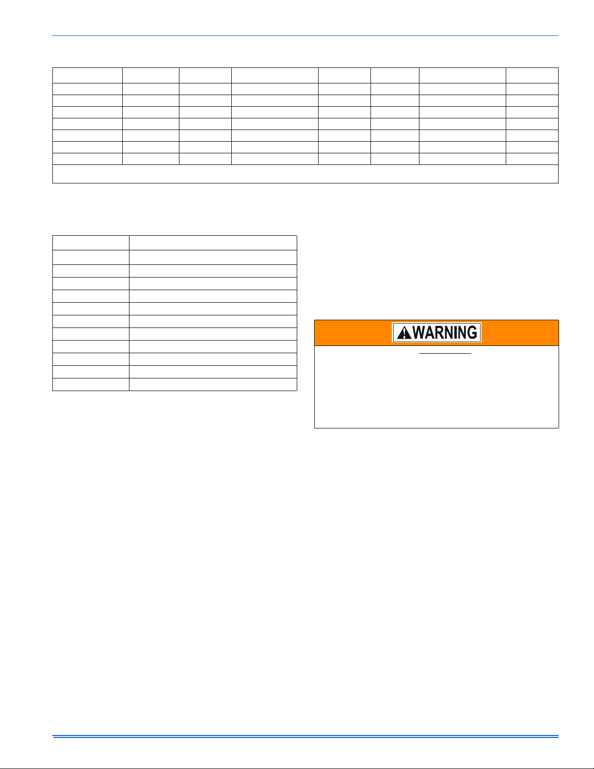
Unit Clearances to Combustibles
Application
Upflow 1 (2.5) 3 (7.6) 0 (0) 0 (0) 0 (0) 0 (0) Combustible Yes Yes
Top Front Rear Left Side Right Side Flue
In. (cm) In. (cm) In. (cm) In. (cm) In. (cm) In. (cm)
Floor/
Bottom
Closet
Alcove
DUCTWORK INSTALLATION AND SUPPLY PLENUM
CONNECTION
A proper Heat Loss/Gain Calculation should be done on all
installations for proper application of equipment. From this
the operating parameters of the furnace specifications.
Protection Association) as outlined in NFPA pamphlets 90A and
90B (latest editions) or applicable national, provincial, or state, and
local fire and safety codes.
lar Home installations, when a furnace is installed so that the supply ducts carry air circulated by the furnace to areas outside the
space containing the furnace, the return air shall also be handled
by a duct(s) sealed to the furnace casing and terminating outside
the space containing the furnace.
air conditioning and heating equipment and to and from the conditioned space.
approved flexible duct connector is recommended on all installations to
prevent noise transmission. All connections should be sealed to prevent
air leakage. Sheet metal should be crosshatched to eliminate any popping when the indoor fan is energized.
When replacing an existing furnace, if the existing supply plenum is not
the same size as the new furnace then the existing plenum must be
removed and a new plenum installed that is of the proper size for the
new furnace. The minimum plenum height is 12” (30 cm). If the plenum
is shorter than 12” (30 cm) the turbulent air flow may cause the limit
controls not to operate as designed if at all.
NOTE: When attaching duct flange, do not shoot the screw down into
the casing. Use the formed flange intended for duct flange attachment.
The duct system is a very important part of the installation. If the duct
system is improperly sized the furnace will not operate properly.
The ducts attached to the furnace plenum should be of sufficient size so
that the furnace operates at the specified external static pressure and
within the air temperature rise specified on the nameplate.
Table 2 is a guide for determining whether the rectangular duct system
that the furnace is being connected to be of sufficient size for proper furnace operation.
Use the Example below to help you in calculating the duct area to determine whether the ducts have sufficient area so that the furnace operates at the specified external static pressure and within the air
temperature rise specified on the nameplate.
The following are general duct sizing guidelines that may not serve to
requirements of every application.
Example: The furnace input is 80,000 BTUH, 1,200 CFM blower
requirement. The recommended duct area is 216 sq.in, there are two 8
x 12 rectangular ducts attached to the plenum and there are two 7 inch
round ducts attached to the furnace.
1. Take 8 x 12, which equals 96 square inch x 2 = 192 square inches
2. The square inch area for 7 inch round ducts, 38.4 square inch x 2
3. Then take the 192 square inch from the rectangular duct and add it
In this example, the duct system attached to the plenum has a sufficient
area so that the furnace operates at the specified external static pressure and within the air temperature rise specified on the nameplate.
Providing the return duct is properly sized as well.
the ductwork sizing can be calculated, ACCA Manual J and
D and industry standards are helpful.
Attach the supply plenum to the furnace or coil outlet duct
connection flanges. This is typically through the use of S
cleat material when a metal plenum is used. The use of an
then go to round duct size located in Table 3.
= 76.8 square inches,
to the 76.8 square inch of round duct. The total square inch of duct
attached to the furnace supply plenum is 268.8 square inches.
This exceeds the recommended 216 square inch of duct.
Attic
4 Unitary Products Group
Page 5
292278-UIM-A-0108
TABLE 2:
Minimum Duct Sizing For Proper Airflow
Input Airflow
Return
1
Rectangular
2
Round
2
Supply
3
Rectangular
2
Round
2
BTU/H (kW) CFM (m³) In² (cm²) in. x in. (cm x cm) in. (cm) dia. In² (cm²) in. x in. (cm x cm) in. (cm) dia.
60,000 (17.6) 1,200 (34.0) 280 (1806) 14 x 20 (35.6 x 50.8) 18 (45.7) 216 (1393) 12 x 18 (30.5 x 45.7) 16 (40.6)
80,000 (23.4) 1,200 (34.0) 280 (1806) 14 x 20 (35.6 x 50.8) 18 (45.7) 216 (1393) 12 x 18 (30.5 x 45.7) 16 (40.6)
80,000 (23.4) 1,600 (45.3) 360 (2322) 18 x 20 (45.7 x 50.8) 22 (55.8) 280 (1806) 14 x 20 (35.6 x 50.8) 18 (45.7)
100,000 (29.3) 1,600 (45.3) 360 (2322) 18 x 20 (45.7 x 50.8) 22 (55.8) 280 (1806) 14 x 20 (35.6 x 50.8) 18 (45.7)
100,000 (29.3) 2,000 (56.6) 440 (2838) 20 x 22 (50.8 x 55.8) 24 (60.9) 390 (2516) 16 x 22 (40.6 x 55.8) 22 (55.8)
120,000 (35.2) 2,000 (56.6) 440 (2838) 20 x 22 (50.8 x 55.8) 24 (60.9) 390 (2516) 16 x 22 (40.6 x 55.8) 22 (55.8)
NOTE: This chart does not replace proper duct sizing calculations or take into account static pressure drop for run length and fittings. Watch out for the temperature rise
and static pressures.
1. Maximum return air velocity in rigid duct @ 700 feet per minute (213 m/min).
2. Example return main trunk duct minimum dimensions.
3. Maximum supply air velocity in rigid duct @ 900 feet per minute (274m/min).
TABLE 3:
Round Duct Size
Round Duct Size Calculated Area For Each Round Duct Size
inches (cm)
Sq.in (cm
2
)
5 (13) 19.6 (126)
6 (15) 28.2 (182)
7 (18) 38.4 (248)
8 (20) 50.2 (324)
IMPORTANT: The minimum plenum height is 12” (30 cm). The furnace
will not operate properly on a shorter plenum height. The minimum recommended rectangular duct height is 4” (10 cm) attached to the plenum.
IMPORTANT: The air temperature rise should be taken only after the
furnace has been operating for at least 15 minutes. Temperatures and
external static pressures should be taken 6” (15 cm) past the first bend
from the furnace in the supply duct and the return duct. If an external filter box or an electronic air cleaner is installed, take the return air readings before the filter box or air cleaner.
9 (23) 63.6 (410)
10 (25) 78.5 (506)
11 (28) 95 (613)
12 (30) 113.1 (730)
13 (33) 132.7 (856)
14 (36) 153.9 (993)
1. The Air Temperature Rise is determined by subtracting the Return
Air Temperature Reading from the Supply Air Temperature Reading.
2. The External Static Pressure is determined by adding the Supply
Duct Static Pressure reading to the Return Duct Static Pressure
reading and adding the pressure drop across any applied coil.
TABLES 2 and 3 are to be used as a guide only to help the installer
determine if the duct sizes are large enough to obtain the proper air flow
(CFM) through the furnace. TABLES 2 and 3 ARE NOT to be used to
design ductwork for the building where the furnace is being installed.
There are several variables associated with proper duct sizing that are
The supply air temperature MUST NEVER exceed the Maximum
Supply Air Temperature, specified on the nameplate.
Operating the furnace above the maximum supply air temperature
will cause the heat exchanger to overheat, causing premature heat
exchanger failure. Improper duct sizing, dirty air filters, incorrect
manifold pressure, incorrect gas orifice and/or a faulty limit switch
can cause the furnace to operate above the maximum supply air
temperature. Refer to sections II and III for additional information on
correcting the problem.
If a matching cooling coil is used, it may be placed directly on the furnace outlet and sealed to prevent leakage. Follow the coil instructions
for installing the supply plenum. On all installations without a coil, a
removable access panel is recommended in the outlet duct such that
smoke or reflected light would be observable inside the casing to indicate the presence of leaks in the heat exchanger. This access cover
shall be attached in such a manner as to prevent leaks.
not included in the tables. To properly design the ductwork for the building, Refer to the ASHRAE Fundamentals Handbook, Chapter on
“DUCT DESIGN” or a company that specializes in Residential and Modular Home duct designs.
Unitary Products Group 5
Page 6
292278-UIM-A-0108
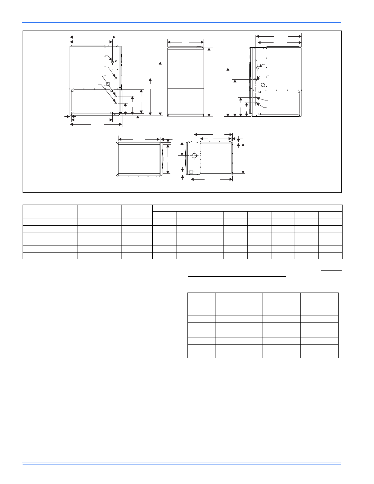
26-1/2
24-5/8
1-1/2” GAS
PIPE ENTRY
7/8” JUNCTION
BOX HOLE
T-STAT WIRING
7/8” K.O.
CONDENSATE
DRAIN 7/8” K.O.
OPTIONAL RETURN AIR
CUT-OUT (either side)
FOR USE WITH
EXTERNAL FILTER
FRAME
7/8
LEFT SIDE
23-3/4
30-1/8
21-1/2
13-7/8
11
7
7/8
26-3/4
BOTTOM IMAGE
RETURN END
30-7/8
1-3/8
C
1-1/4
A
FRONT
D
2
40
24-3/8
20
24-17/16
TOP IMAGE
SUPPLY END
28-3/8
21-1/2
5/8
11
8
5/8
B
26-1/2
25-3/8
1-1/2” GAS
PIPE ENTRY
7/8” JUNCTION
BOX HOLE
T-STAT WIRING
7/8” K.O.
CONDENSATE
DRAIN 7/8” K.O.
RIGHT SIDE
FIGURE 1: Dimensions
BTUH (kW)
Input
(m
CFM
3
/min)
Cabinet
Size
A (in.) A (cm) B (in.) B (cm) C (in.) C (cm) D (in.) D (cm)
Cabinet Dimension
60 (17.6) 1200 (34.0) B 17-1/2 44.4 16-1/4 41.3 14-1/2 36.8 8-1/2 21.6
80 (23.4) 1200 (34.0) B 17-1/2 44.4 16-1/4 41.3 11 36.8 8-1/2 21.6
80 (23.4) 1600 (45.3) C 21 53.3 19-3/4 50.2 18 45.7 8-7/8 22.5
100 (29.3) 1600 (45.3) C 21 53.3 19-3/4 50.2 18 45.7 8-7/8 22.5
100 (29.3) 2000 (56.6) C 21 53.3 19-3/4 50.2 18 45.7 8-7/8 22.5
120 (35.2) 2000 (56.6) D 24-1/2 62.2 23-1/4 59.4 21-1/2 54.6 10-5/8 27.0
RESIDENTIAL AND NON HUD MODULAR HOME
RETURN PLENUM CONNECTION
Return air may enter the furnace through the side(s) or bottom depending on the type of application. Return air may not be connected into the
rear panel of the unit. In order to stay within the velocity rating of the filter(s), it is recommended that applications over 1800 CFM (57 m³/min)
use return air from two sides, one side and the bottom or bottom only.
For single return application, see data and notes on blower performance data tables in this manual.
BOTTOM RETURN AND ATTIC INSTALLATIONS
Bottom return applications normally pull return air through a base platform or return air plenum. Be sure the return platform structure or return
air plenum is suitable to support the weight of the furnace.
The furnace base is equipped with a rectangular blockoff panel that can
be removed by performing the following steps:
1. Lay the furnace on its back.
2. Remove the screws from the toe plate and remove the toe plate.
3. Pull the base plate out of the furnace and re-install the toe plate.
4. Be sure to seal the furnace to plenum connections to prevent air
leakage. Refer to Figure 1 for unit and plenum dimensions.
Attic installations must meet all minimum clearances to combustibles
and have floor support with required service accessibility.
IMPORTANT: When an external mounted filter rack is being used see
the instructions provided with that accessory for proper hole cut size.
SECTION IV: FILTERS
FILTER INSTALLATION
All applications require the use of a filter. Replacement filter size is
shown in Table 4.
Filters must be installed external to the furnace cabinet. DO NOT
attempt to install filters inside the furnace.
TABLE 4:
BTU/H (kW)
Recommended Filter Sizes
(m
CFM
3
/min)
Input
Cabinet
Size
Side Return
Filter in. (cm)
Bottom Return
Filter in. (cm)
60 (17.8) 1200 (34.0) B 16 x 25 (41 x 64) 16 x 25 (41 x 64)
80 (23.4) 1200 (34.0) B 16 x 25 (41 x 64) 16 x 25 (41 x 64)
80 (23.4) 1600 (45.3) C 16 x 25 (41 x 64) 20 x 25 (51 x 64)
100 (29.3) 1600 (45.3) C 16 x 25 (41 x 64) 20 x 25 (51 x 64)
100 (29.3) 2000 (56.6) C 16 x 25 (41 x 64) 20 x 25 (51 x 64)
120 (35.1) 2000 (56.6) D
NOTES:
1. Air velocity through throwaway type filters may not exceed 300 feet
per minute. All velocities over this require the use of high velocity filters.
2. Air flows above 1800 CFM require either return from two sides or
one side plus bottom.
(2) 16 x 25
(2) (41 x 64)
22 x 25 (56 x 64)
SIDE RETURN - FILTER INSTALLATION
Locate and mark the side return opening. Refer to Figure 1 for dimensions of the cutout.
Install the side filter rack following the instructions provided with that
accessory. If a filter(s) is provided at another location in the return air
system, the ductwork may be directly attached to the furnace side
panel.If not provided with the furnace, an accessory filter rack is available for mounting the filter external to the cabinet.
6 Unitary Products Group
Page 7
292278-UIM-A-0108
IMPORTANT: Some accessories such as electronic air cleaners and
pleated media may require a larger side opening. Follow the instructions supplied with that accessory for side opening requirements. Do
not cut the opening larger than the dimensions shown in Figure 1.
All installations must have a filter installed.
SECTION V: GAS PIPING
GAS SAFETY
An overpressure protection device, such as a pressure regulator,
must be installed in the gas piping system upstream of the furnace
and must act to limit the downstream pressure to the gas valve so it
does not exceed 0.5 PSI {14" w.c. (3.48 kPa)}. Pressures exceeding 0.5 PSI {14” w.c. (3.48 kPa)} at the gas valve will cause damage
to the gas valve, resulting in a fire or explosion or cause damage to
the furnace or some of its components that will result in property
damage and loss of life.
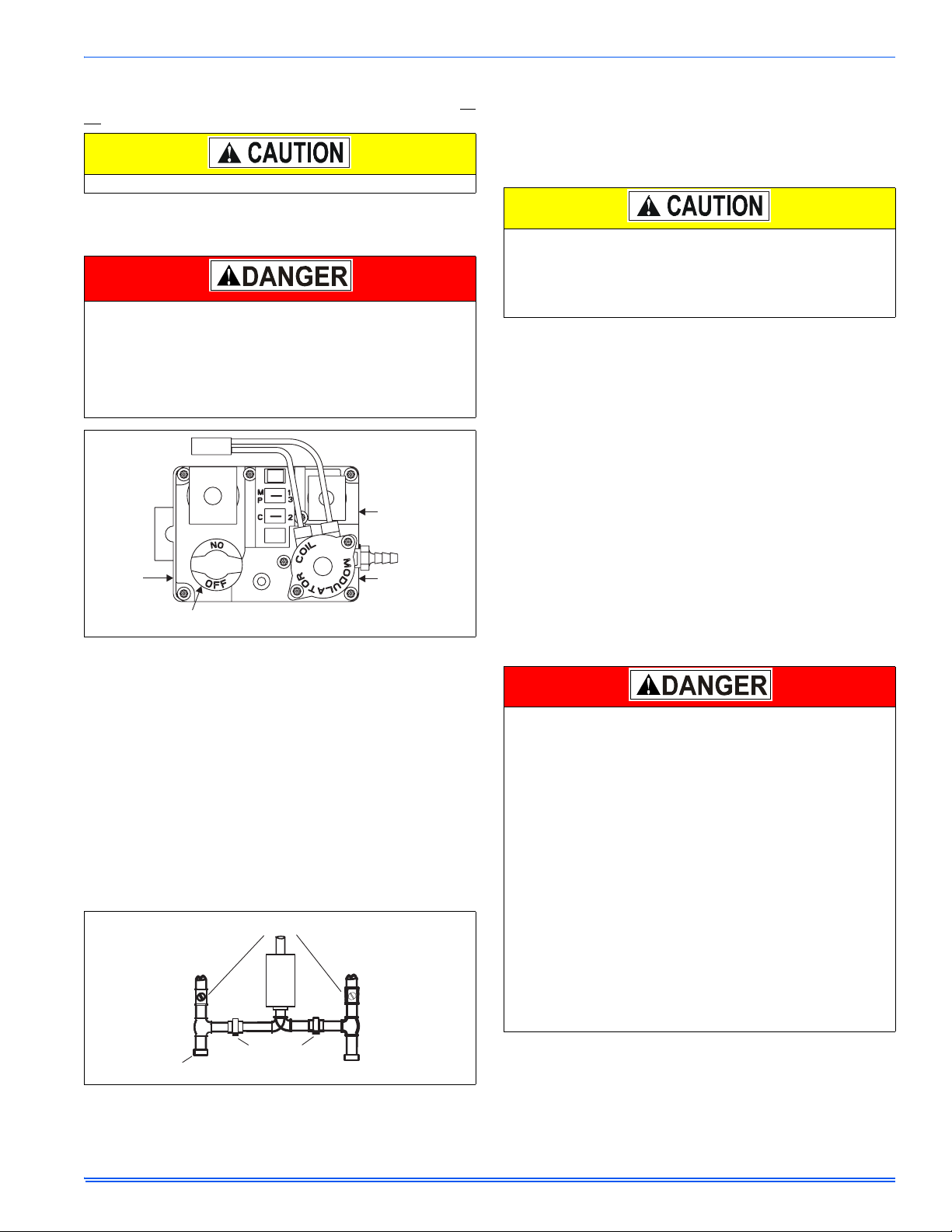
MAIN
REGULATOR
ADJUSTMENT
INLET
PRESSURE
TAP
ON/OFF
KNOB
FIGURE 2: Gas Valve
IMPORTANT: Plan your gas supply before d etermining the correct gas
pipe entry. Use 90-degree service elbow(s), or short nipples and conventional 90-degree elbow(s) to enter through the cabinet access holes.
GAS PIPING INSTALLATION
Properly sized wrought iron, approved flexible or steel pipe must be
used when making gas connections to the unit. If local codes allow the
use of a flexible gas appliance connection, always use a new listed connector. Do not use a connector that has previously serviced another gas
appliance.
Some utility companies or local codes require pipe sizes larger than the
minimum sizes listed in these instructions and in the codes. The furnace
rating plate and the instructions in this section specify the type of gas
approved for this furnace - only use those approved gases. The installation of a drip leg and ground union is required. Refer to Figure 3.
EXTERNAL MANUAL
SHUTOFF VALVE
TO GAS
SUPPLY
TO GAS
SUPPLY
OUTLET
PRESSURE
TAP
IMPORTANT: An accessible manual shutoff valve must be installed
upstream of the furnace gas controls and within 6 feet (1.8 m) of the furnace.
The furnace must be isolated from the gas supply piping system by
closing its individual external manual shutoff valve during any pressure
testing of the gas supply piping system at pressures equal to or greater
than 1/2 psig (3.5 kPa).
The gas valve body is a very thin casting that cannot take any
external pressure. Never apply a pipe wrench to the body of the gas
valve when installing piping. A wrench must be placed on the octagonal hub located on the gas inlet side of the valve. Placing a wrench
to the body of the gas valve will damage the valve causing improper
operation and/or the valve to leak.
Gas piping may be connected from either side of the furnace using any
of the gas pipe entry knockouts on both sides of the furnace. Refer to
Figure 1 dimensions.
The inlet to the gas valve lines up directly with the opening in the left
side of the furnace casing. To line up with the opening in the right side
of the casing, two street ells should be used.
GAS ORIFICE CONVERSION FOR PROPANE (LP)
This furnace is constructed at the factory for natural gas-fired operation,
but may be converted to operate on propane (LP) gas by using a factory-supplied LP conversion kit which contains a new gas valve. Follow
the instructions supplied with the LP kit. Refer to the instructions in the
propane (LP) conversion kit for the proper gas orifice size.
HIGH ALTITUDE OPERATION
This furnace is constructed at the factory for natural gas-fired operation
at 0 – 4,000 ft. (0 m – 1220 m) above sea level.
At elevations above 4,000 feet, the furnace will automatically reduce it’s
input rate if necessary to maintain good combustion. If the natural gas
being supplied has also been derated by the gas supplier, it may be
necessary to increase the orifice size in order to achieve the rated input.
PROPANE
It is very important to choose the correct kit and/or gas orifices for
the altitude and the type of gas for which the furnace is being
installed.
Only use natural gas in furnaces designed for natural gas. Only use
propane (LP) gas for furnaces that have been properly converted to
use propane (LP) gas. Do not use this furnace with butane gas.
Incorrect gas orifices or a furnace that has been improperly converted will create an extremely dangerous condition resulting in premature heat exchanger failure, excessive sooting, high levels of
carbon monoxide, personal injury, property damage, a fire hazard
and/or death.
Propane (LP) conversions are required in order for the appliance to
satisfactory meet the application.
An authorized distributor or dealer must make all gas conversions.
The installer must take every precaution to insure that the furnace
has been converted to the proper gas orifice size when the furnace
is installed. Do not attempt to drill out any orifices to obtain the
proper orifice size. Drilling out a gas orifice will cause misalignment
of the burner flames, causing premature heat exchanger burnout,
high levels of carbon monoxide, excessive sooting, a fire hazard,
personal injury, property damage and/or death.
DRIP
LEG
GROUNDED JOINT UNION
MAY BE INSTALLED
INSIDE OR OUTSIDE UNIT.
FIGURE 3: Gas Piping
Unitary Products Group 7
Page 8
292278-UIM-A-0108
SECTION VI: ELECTRICAL POWER
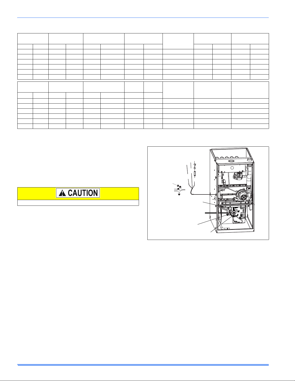
TABLE 5:
MBH kW MBH kW In. cm HP Amps °F °C °F °C
60/21 18/6 57/20 17/6 11 x 8 27.9 x 20.3 1/2 7.7 20 40 - 70 22 - 39 20 - 50 11 - 28
80/28 23/8 76/26 22/8 11 x 8 27.9 x 20.3 1/2 7.7 20 40 - 70 22 - 39 20 - 50 11 - 28
80/28 23/8 76/26 22/8 11 x 10 27.9 x 25.4 3/4 9.6 20 40 - 70 22 - 39 20 - 50 11 - 28
100/35 29/10 95/33 28/10 11 x 10 27.9 x 25.4 3/4 9.6 20 40 - 70 22 - 39 20 - 50 11 - 28
100/35 29/10 95/33 28/10 11 x 11 27.9 x 27.9 1 12.8 20 40 - 70 22 - 39 20 - 50 11 - 28
120/42 35/12 115/39 34/11 11 x 11 27.9 x 27.9 1 12.8 20 40 - 70 22 - 39 20 - 50 11 - 28
Annual Fuel Utilization Efficiency (AFUE) numbers are determined in accordance with DOE Test procedures.
Wire size and over current protection must comply with the National Electrical Code (NFPA-70-latest edition) and all local codes.
The furnace shall be installed so that the electrical components are protected from water.
ELECTRICAL POWER CONNECTIONS
All models use nominal 115 VAC, 1 Phase, 60-Hertz power supply. DO
NOT CONNECT THIS APPLIANCE TO A 50 HZ POWER SUPPLY OR
A VOLTAGE ABOVE 130 VOLTS.
Field wiring to the unit must be grounded. Electric wires that are field
installed shall conform to the temperature limitation for 63°F (35°C) rise
wire when installed in accordance with instructions. Refer to Table 5 in
these instructions for specific furnace electrical data.
Electrical and Performance Data
Input
Max/Min
Output Max/Min Blower Size Blower
Max.
Over-current
Air Temp. Rise
Maximum Input
Air Temp. Rise
Minimum Input
Protect
Max. Outlet
Air Temp.
Nominal Airflow Cabinet Width
°F °C CFM
3
/min
m
In. cm Amps %
Total
Unit
AFUE
Min. Wire Size
(awg) @ 75 ft.
One Way
Approximate
Operating Weight
Power Supply
(Voltage-PH-Hz)
170 76.7 1200 34.0 17-1/2 44.4 9 95.0 14 135 115-1-60
170 76.7 1200 34.0 17-1/2 44.4 9 95.0 14 142 115-1-60
170 76.7 1600 45.3 21 53.3 12 95.0 14 157 115-1-60
170 76.7 1600 45.3 21 53.3 12 95.0 14 162 115-1-60
170 76.7 2000 56.6 21 53.3 14 95.0 12 164 115-1-60
170 76.7 2000 56.6 24-1/2 62.2 14 95.0 12 180 115-1-60
L1
HOT
N
GND
WHT
BLK/BLK
WHT/WHT
GRN/GRN
GRN
BLK
Use copper conductors only.
SUPPLY VOLTAGE CONNECTIONS
IMPORTANT: The power con nection leads and wir in g box may be relo cated to the left side of the furnace. Remove the screws and cut wire tie
holding excess wiring. Reposition on the left side of the furnace and fasten using holes provided.
1. Provide a power supply separate from all other circuits. Install
overcurrent protection and disconnect switch per local/national
electrical codes. The switch should be close to the unit for convenience in servicing. With the disconnect or fused switch in the OFF
position, check all wiring against the unit wiring label. Refer to the
wiring diagram shown in Figure 26.
2. Remove the screws retaining the junction box cover. Route the
power wiring through the opening in the unit into the junction box
with a conduit connector or other proper connection. In the junction box there will be three wires, a Black Wire, a White Wire and a
Green Wire. Connect the power supply as shown on the unit-w iring label on the inside of the blower compartment door or Figure 4.
The black furnace lead must be connected to the L1 (hot) wire
from the power supply. The white furnace lead must be connected
to neutral. Connect the green furnace lead (equipment ground) to
the power supply ground. An alternate wiring method is to use a
field provided 2” (5.08 cm) x 4” (10.2 cm) box and cover on the
outside of the furnace. Route the furnace leads into the box using
a protective bushing where the wires pass through the furnace
panel. After making the wiring connections replace the wiring box
cover and screws.
3. The furnace's control system requires correct polarity of the power
supply and a proper ground connection. If the power supply polarity is reversed, the control board will flash 9 times. The furnace will
not operate until the polarity is corrected. Refer to “Furnace Diagnostics” section of the “User’s Information, Maintenance, & Service Manual provided with this furnace.
TRANSFORMER
CLASS 2 SYSTEM
CONTROL WIRING
TO THERMOSTAT
BLOWER
COMPARTMENT
DOOR SWITCH
115 VAC
CONTROL
BOARD
FIGURE 4: Electrical Wiring
LOW VOLTAGE CONTROL WIRING CONNECTIONS
Install the field-supplied thermostat by following the instructions that
come with the thermostat. With the thermostat set in the OFF position
and the main electrical source disconnected, connect the thermostat
wiring from the wiring connections on the thermostat to the terminal
strip on the furnace control board, as shown in Figures 5-9. Electronic
thermostats may require the common wire to be connected to the "C"
terminal as shown in Figures 5-9. Apply strain relief to thermostat wires
passing through cabinet. If air conditioning equipment is installed, use
thermostat wiring to connect the Y and C terminals on the furnace control board to the condensing unit (unit outside) as shown in Figures 5-9.
IMPORTANT: Set the heat anticipator in the room thermostat to 0.10
amps. Setting it lower will cause short cycles. Setting it higher will cause
the room temperature to exceed the set points.
IMPORTANT: Some electronic thermostats do not have adjustable heat
anticipators. They should be set to six cycles per hour. Follow the thermostat manufacturer's instructions.
The 24-volt, 40 VA transformer is sized for the furnace components
only, and should not be connected to power auxiliary devices such as
humidifiers, air cleaners, etc. The transformer may provide power for an
air conditioning unit contactor.
8 Unitary Products Group
Page 9
292278-UIM-A-0108
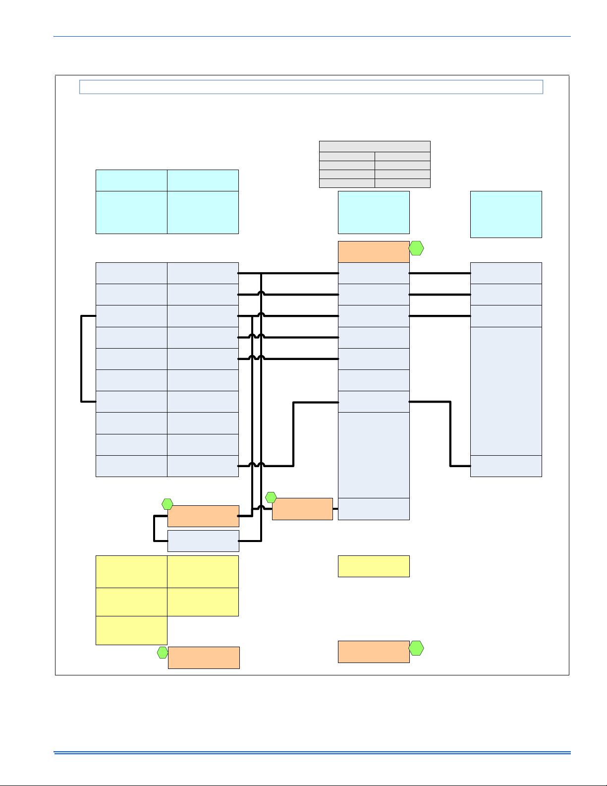
For additional connection diagrams for all UPG equipment refer to “Line Voltage System Wiring” document available on-line at www.upgnet.com in
the Product Catalog Section.
AC 26A Two Stage Air Conditioner – Variable Speed Modulating Furnace
ID MODELS
PC9
FC9C
THERMOSTAT
THERMOSTAT
FL9C
*DN22U00124
C
24 – Volt Common
Y1
First Stage Compressor
R
24 – Volt Hot
(Heat XFMR)
G
Fan
E/W1
First Stage Heat
W2
Second Stage Heat
R
24 – Volt Hot
(Cool XFMR)
Y2
Second Stage
Compressor
*PP32U70124
C
24 – Volt Common
Y1
First Stage Compressor
R
24 – Volt Hot
(Heat XFMR)
G
Fan
E/W1
Emergency Heat
AUX
Auxiliary Heat
R
24 – Volt Hot
(Cool XFMR)
Y2
Second Stage
Compressor
VARIABLE SPEED
MODULATING
FURNACE
VARIABLE SPEED
MODULATING
FURNACE CONTROL
C
24 – Volt Common
Single Stage Compressor
Y1
R
24 – Volt Hot
G
Fan
W
Modulating Heat
Y/Y2
Second or Full
Stage Compressor
TWO STAGE
AIR
CONDITIONER
1
C
24 – Volt Common
Y1
First Stage Compressor
R
24 – Volt Hot
Y2
Second Stage
Compressor
Connection of the “C”
terminal, 24-volt common
is optional when used with
batteries
Thermostat Installer Setup
1-System Type-must
be set to 6-2 Heat/2 Cool
Multistage Conventional
Thermostat Installer Setup
15-Compressor Protection
-must be set to 5
2
External Humidistat
(Optional)
Open on Humidity Rise
24VAC Humidifier
(Optional)
Connection of the “C”
terminal, 24-Volt common
is optional when used with
batteries
Thermostat Installer Setup
0170-System Type-must
be set to 8-2 Heat/2 Cool
Multistage Conventional
2
Part Number:
S1-2HU16700124
2
External Humidistat
(Optional)
Open on Humidity Rise
HUM
Dehumidification-
Open on Humidity Rise
Move HUMIDISTAT
jumper to “YES”
if humidistat is to be used.
Part Numbers:
SAP = Legacy
171334 = 031-09153
1
FIGURE 5: Thermostat Chart – Two Stage AC - Variable Speed Modulating Furnace
Unitary Products Group 9
Page 10
292278-UIM-A-0108
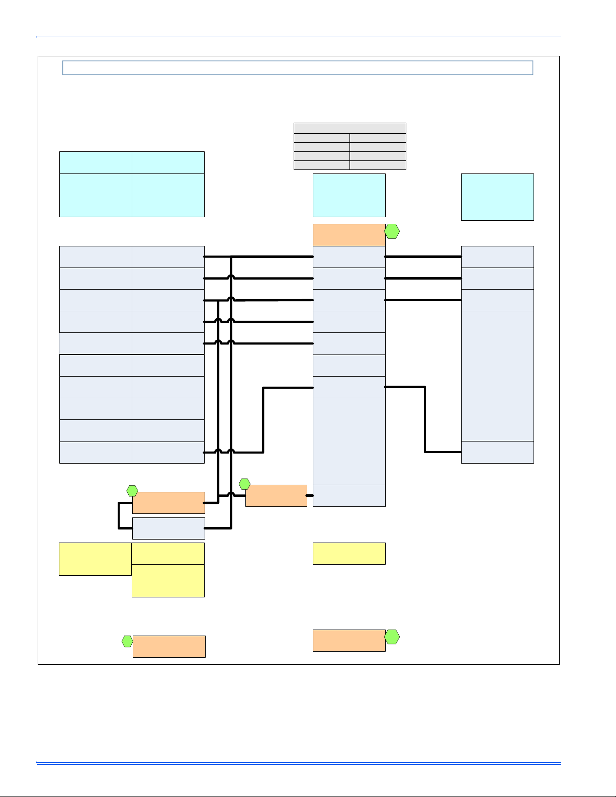
AC 26B Two Stage Air Conditioner – Variable Speed Modulating Furnace
THERMOSTAT
THERMOSTAT
ID MODELS
PC9
FC9C
FL9C
*DN22C00124
C
24 – Volt Common
Y
First Stage Compressor
R
24 – Volt Hot
G
Fan
W
First Stage Heat
W2
Second Stage Heat
Y2
Second Stage
Compressor
*DP22U70124
C
24 – Volt Common
Y1
First Stage Compressor
R
24 – Volt Hot
G
Fan
E/W1
First Stage Heat
W2
Second Stage Heat
Y2
Second Stage
Compressor
VARIABLE SPEED
MODULATING
FURNACE
VARIABLE SPEED
MODULATING
FURNACE CONTROL
C
24 – Volt Common
Single Stage Compressor
Y1
R
24 – Volt Hot
G
Fan
W
Modulating Heat
Y/Y2
Second or Full
Stage Compressor
TWO STAGE
AIR
CONDITIONER
1
C
24 – Volt Common
Y1
First Stage Compressor
R
24 – Volt Hot
Y2
Second Stage
Compressor
Connection of the “C”
terminal, 24-Volt common
is optional when used with
batteries
2
External Humidistat
(Optional)
Open on Humidity Rise
24VAC Humidifier
(Optional)
Step 1 of Thermostat User
Configuration Menu must
be set to MS 2
Connection of the “C”
terminal, 24-Volt common
is optional when used with
batteries
2
Part Number:
S1-2HU16700124
2
External Humidistat
(Optional)
Open on Humidity Rise
HUM
Dehumidification-
Open on Humidity Rise
Move HUMIDISTAT
jumper to “YES”
if humidistat is to be used.
Part Numbers:
SAP = Legacy
171334 = 031-09153
1
FIGURE 6: Thermostat Chart – Two Stage AC - Variable Speed Modulating Furnace
10 Unitary Products Group
Page 11
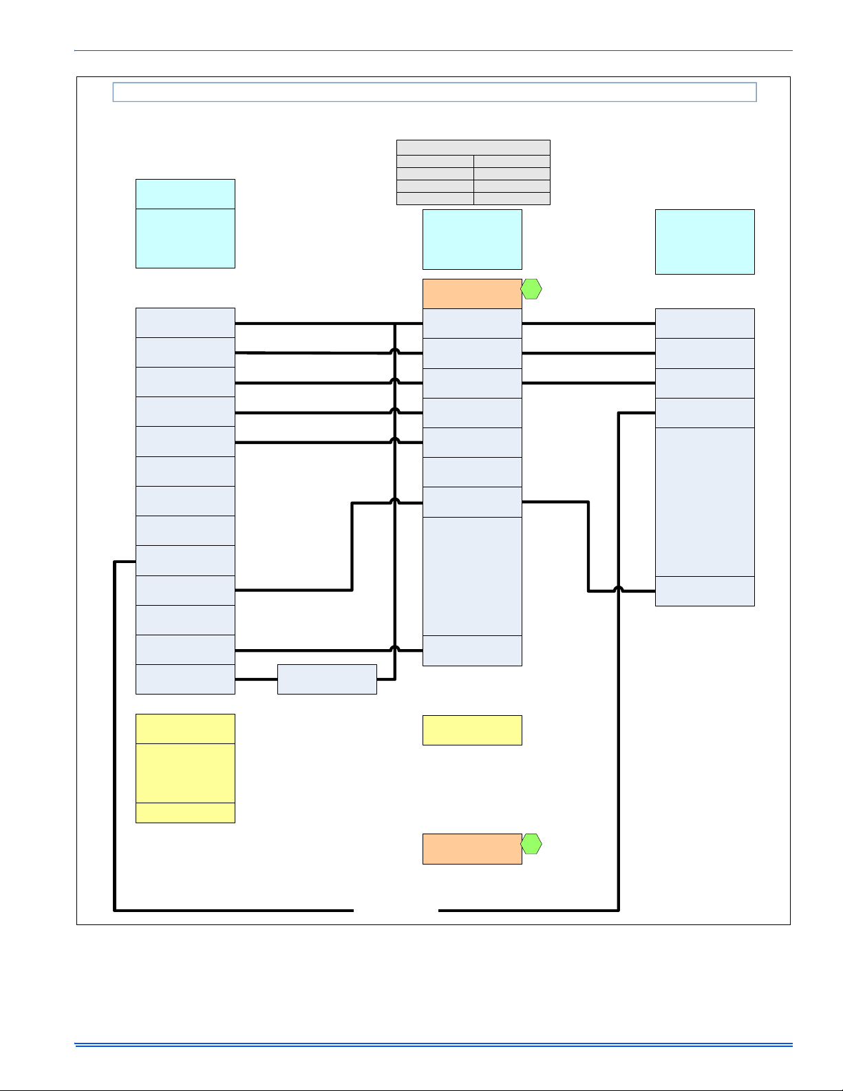
AC 26C Two Stage Air Conditioner – Variable Speed Modulating Furnace
ID MODELS
PC9
FC9C
THERMOSTAT
FL9C
292278-UIM-A-0108
*PP32U71124
*PP32U72124
C
24 – Volt Common
Y1
First Stage Compressor
R
24 – Volt Hot
G
Fan
E/W1
First Stage Heat
W2
Second Stage Heat
L
Malfunction Light
Y2
Second Stage
Compressor
VARIABLE SPEED
MODULATING
FURNACE
VARIABLE SPEED
MODULATING
FURNACE CONTROL
C
24 – Volt Common
Single Stage Compressor
Y1
R
24 – Volt Hot
G
Fan
W
Modulating Heat
Y/Y2
Second or Full
Stage Compressor
TWO STAGE
AIR
CONDITIONER
1
C
24 – Volt Common
Y1
First Stage Compressor
R
24 – Volt Hot
Comfort Alert Interface
(two pin connector)
Y2
Second Stage
Compressor
DHM
Dehumidification
HM
Humidistat
Step 1 of Thermostat User
Configuration Menu must
be set to MLTISTG
Step 16 of Thermostat
Installer Table Menu
must be set to ON to use
Comfort Alert Features
Only applies to
*PP32U72124
E2/P Switch must be in the
E2 position
24VAC Humidifer
(Optional)
HUM
Dehumidification-
Open on Humidity Rise
Move HUMIDISTAT
jumper to “YES”
if humidistat is to be used.
Part Numbers:
SAP = Legacy
171334 = 031-09153
Optional Harness
FIGURE 7: Thermostat Chart – Two Stage AC - Variable Speed Modulating Furnace
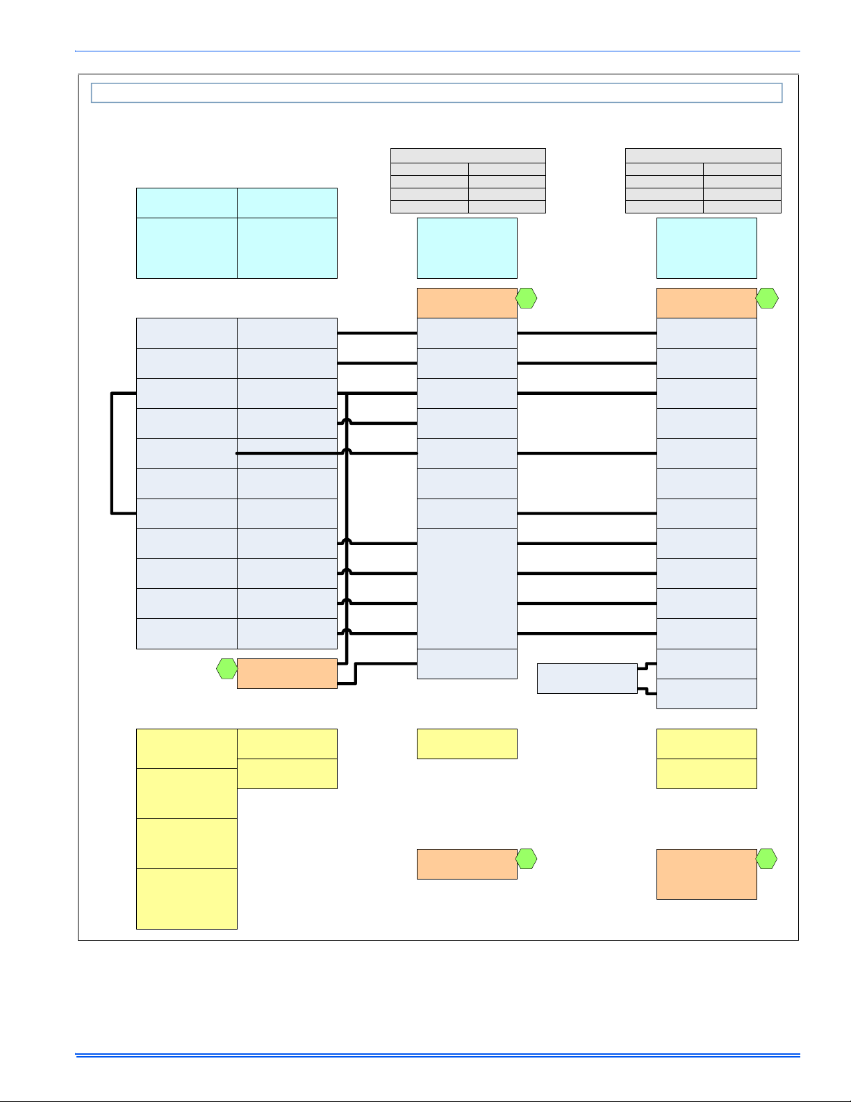
1
Unitary Products Group 11
Page 12
292278-UIM-A-0108
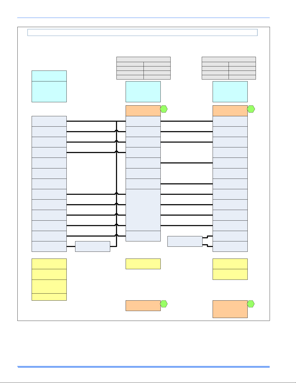
HP 28A Two Stage Heat Pump – Variable Speed Modulating Furnace (With Hot Heat Pump Operation)
THERMOSTAT
*PP32U71124
*PP32U72124
C
24 – Volt Common
Y1
First Stage Compressor
R
24 – Volt Hot
G
Fan
W2
Second Stage Aux. Heat
O
Reversing Valve
Energized in Cool
L
Malfunction Light
Second Stage Compressor
Y2
E/W1
First Stage Aux. Heat
DHM
Dehumidistat
HM
Humidistat
24VAC Humidifier
(Optional)
ID MODELS
PC9
FC9C
FL9C
VARIABLE SPEED
MODULATING
FURNACE
VARIABLE SPEED
MODULATING
FURNACE CONTROL
C
24 – Volt Common
Single Stage Compressor
Y1
R
24 – Volt Hot
G
Fan
W
Modulating Heat
Y/Y2
Second or Full
Stage Compressor
HUM
Dehumidification-
Open on Humidity Rise
2
Bonnet Sensor
(Optional)
OD MODELS
YZE
YZH
H*5
H*8
TWO STAGE
HEAT PUMP
YORKGUARD VI
CONTROL
C
24 – Volt Common
Single Stage Compressor
Second Stage Compressor
Second Stage Compressor
Y1
R
24 – Volt Hot
W1 OUT
First Stage Heat
W2 OUT
Second Stage Heat
Y2 OUT
O
Reversing Valve
Energized in Cool
X/L
Malfunction Light
Y2
W
Auxiliary Heat
BSG
Bonnet Sensor
BS
Bonnet Sensor
1
Step 1 of the Thermostat
Installer Table must be
set to Heat Pump
Step 2 of the Thermostat
Installer Table must be
set to 2
Step 5 of Thermostat User
Configuration Menu must
be set to “ON” for
Dehumidification
E2/P Switch must be in the
E2 position
Move HUMIDISTAT
jumper to “YES”
if humidistat is to be used.
Part Numbers:
SAP = Legacy
171334 = 031-09153
2
Change FFuel jumper
on the heat pump control
to “ON”
Change Hot Heat Pump
jumper on the heat pump
control to “ON”
Part Numbers:
SAP = Legacy
126768 = 031-09137
18395 = 031-01996
340512 = 031-09178
1
FIGURE 8: Thermostat Chart – Two Stage HP - Variable Speed Modulating Furnace with Hot Heat Pump Operation
12 Unitary Products Group
Page 13
292278-UIM-A-0108
HP 28C Two Stage Heat Pump – Variable Speed Modulating Furnace (With Hot Heat Pump Operation)
THERMOSTAT
*PP32U70124
C
24 – Volt Common
Y
First Stage Compressor
R
24 – Volt Hot
(Heat XFMR)
G
Fan
E
Emergency Heat
RC
24 – Volt Hot
(Cool XFMR)
O/B
Reversing Valve
L
Malfunction Light
Second Stage Compressor
Y2
AUX
Auxiliary Heat
3
THERMOSTAT
*DN22H00124
*DP22U70124
C
24 – Volt Common
Y1
First Stage Compressor
R
24 – Volt Hot
G
Fan
W2
Second Stage Aux. Heat
O
Reversing Valve
Energized in Cool
L
Malfunction Light
Second Stage Compressor
Y2
E/W1
First Stage Aux. Heat
External Humidistat
(Optional)
Open on Humidity Rise
ID MODELS
PC9
FC9C
FL9C
VARIABLE SPEED
MODULATING
FURNACE
VARIABLE SPEED
MODULATING
FURNACE CONTROL
C
24 – Volt Common
Single Stage Compressor
Y1
R
24 – Volt Hot
G
Fan
W
Modulating Heat
Y/Y2
Second or Full
Stage Compressor
HUM
Dehumidification-
Open on Humidity Rise
2
Bonnet Sensor
(Optional)
OD MODELS
YZE
YZH
H*5
H*8
TWO STAGE
HEAT PUMP
YORKGUARD VI
CONTROL
C
24 – Volt Common
Single Stage Compressor
Second Stage Compressor
Second Stage Compressor
Y1
R
24 – Volt Hot
W1 OUT
First Stage Heat
W2 OUT
Second Stage Heat
Y2 OUT
O
Reversing Valve
Energized in Cool
X/L
Malfunction Light
Y2
W
Auxiliary Heat
BSG
Bonnet Sensor
BS
Bonnet Sensor
1
Thermostat Installer Setup
0170-System Type-
must be set to 12
3 Heat/2 Heat Pump
Thermostat Installer Setup
0190-Changeover Valve-
must be set to 0
O/B terminal
Energized in Cooling
Thermostat Installer Setup
0200-Backup Heat Source-
must be set to 1
Heat Pump Backup Heat
Source is Fossil Fuel
Thermostat Installer Setup
0210-External Fossil Fuel
Kit- must be set to 1
Heat Pump Control
is Controlling Heat Pump
Backup Heat
Step 1 of Thermostat
Installer/Configuration
Menu must be set to “HP2”
Selection of GAS/ELEC
switch on thermostat
not necessary
Move HUMIDISTAT
jumper to “YES”
if humidistat is to be used.
Part Numbers:
SAP = Legacy
171334 = 031-09153
2
Change FFuel jumper
on the heat pump control
to “ON”
Change Hot Heat Pump
jumper on the heat pump
control to “ON”
Part Numbers:
SAP = Legacy
126768 = 031-09137
18395 = 031-01996
340512 = 031-09178
1
FIGURE 9: Thermostat Chart – Two Stage HP - Variable Speed Modulating Furnace with Hot Heat Pump Operation
Unitary Products Group 13
Page 14
292278-UIM-A-0108
ACCESSORY CONNECTIONS
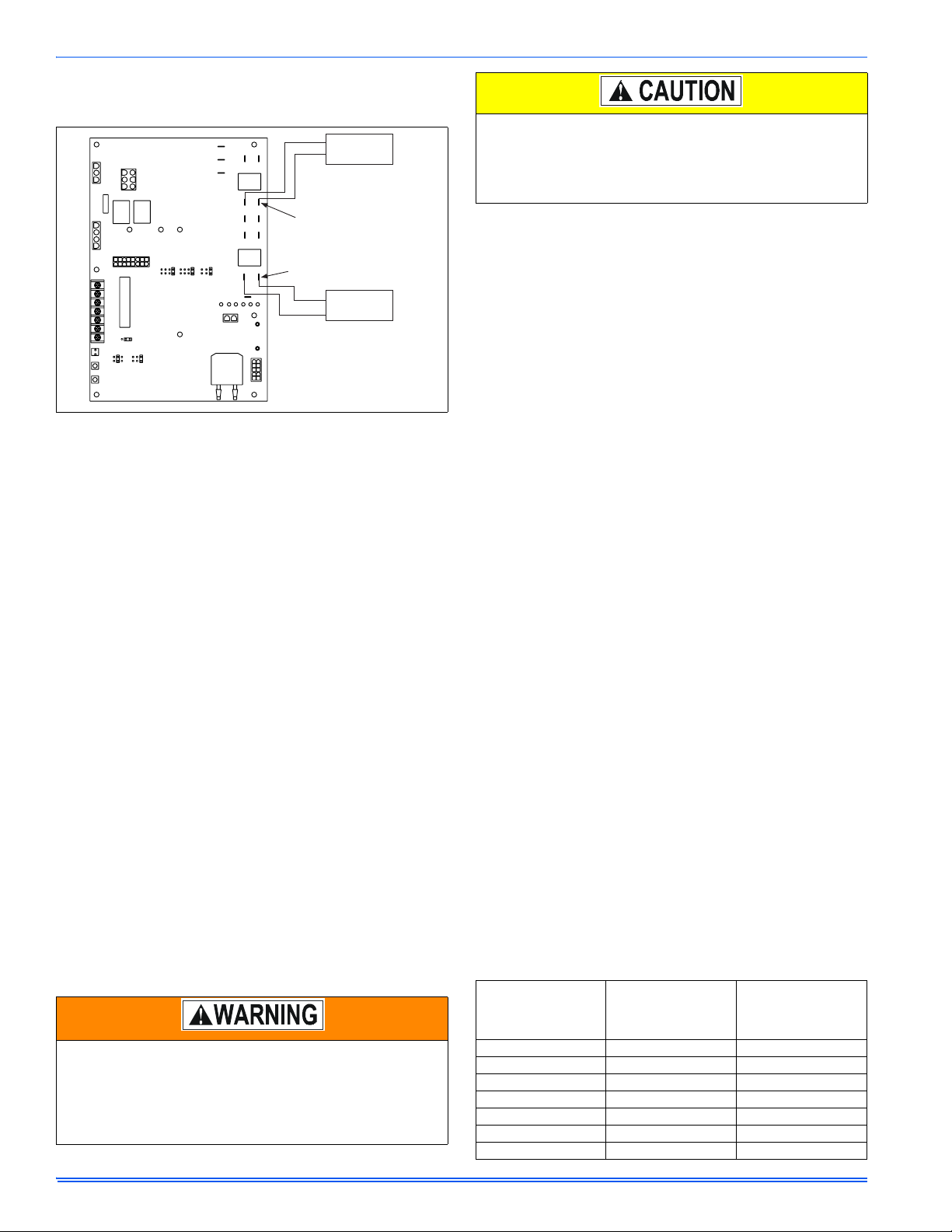
The furnace control will allow power-switching control of various accessories. Refer to Figure 10, for connection details.
BLK
115 VOLT
WHT
HUMIDIFIER
ERROR
TEST
HUMIDISTAT
CONNECTED
NO
YES
AIR
RECIRC
HOT NEU
CFM
DELAY
COOL
ADJUST
HOT NEU
HUMIDIFIER
TERMINALS
EAC
TERMINALS
WHT
BLK
115 VOLT
EAC
FIGURE 10: Accessory Connections
ELECTRONIC AIR CLEANER CONNECTION
Two 1/4” (6.4 mm) spade terminals (EAC and NEUTRAL) for electronic
air cleaner connections are located on the control board. The terminals
provide 115 VAC (1.0 amp maximum) during circulating blower operation.
HUMIDIFIER CONNECTION
Two 1/4” (6.4 mm) spade terminals (HUM and NEUTRAL) for humidifier
connections are located on the control board. The terminals provide 115
VAC (1.0 amp maximum) during heating system operation.
TWINNING
These furnaces are not to be twinned. If more than one furnace is
needed in an application, each furnace must have its own complete
duct system and its own wall thermostat.
SECTION VII: COMBUSTION AIR AND
VENT SYSTEM
COMBUSTION AIR AND VENT SAFETY
This Category IV, dual certified direct vent furnace is desig ned for residential application. It may be installed without modification to the condensate system in a basement, garage, equipment room, alcove, attic
or any other indoor location provided the space temperature is 32 °F
(0°C) or higher and where all required clearance to combustibles and
other restrictions are met. The combustion air and the venting system
must be installed in accordance with Section 5.3, Air for Combustion
and Ventilation, of the National Fuel Gas Code Z223.1/NFPA 54 (latest
edition), or Sections 7.2, 7.3 or 7.4 of CSA B149.1, National Gas and
Propane Codes (latest edition) or applicable provisions of the local
building code and these instructions.
IMPORTANT: The “VENT SYSTEM” must be installed as specified in
these instructions for Residential and Non HUD Modular Homes. The
sealed combustion air / vent system is the only configuration that can
be installed in a Non HUD Modular Home.
When combustion air pipe is installed above a suspended ceiling or
when it passes through a warm and humid space, the pipe must be
insulated with 1/2” Armaflex or other heat resistant type insulation.
Vent piping must be insulated with 1/2” insulation if it will be subjected to freezing temperatures such as routing through unheated
areas or through an unused chimney.
COMBUSTION AIR/VENT PIPE SIZING
The size of pipe required will be determined by the furnace model, the
total length of pipe required and the number of elbows required.
Table 6 lists the maximum equivalent length of pipe allowed for each
model of furnace. The equivalent length of elbows is shown in Table 7.
The equivalent length of the vent system is the total length of straight
pipe PLUS the equivalent length of all of the elbows.
The following rules must also be followed:
1. Long radius (sweep) elbows are recommended. Standard elbows
may be used, but since they have a longer equivalent length, they
will reduce the total length of pipe that will be allowed. Short radius
(plumbing vent) elbows are not allowed. The standard dimensions
of the acceptable elbows are shown below.
2. The maximum equivalent length listed in Table 6 is for the vent piping and the air intake piping separately. For example, if the table
allows 65 equivalent feet for a particular model, then the vent can
have 65 equivalent feet of pipe, AND the combustion air intake can
have another 65 equivalent feet of pipe.
3. Three vent terminal elbows (two for the vent and one for the combustion air intake) are already accounted for and need not be
included in the equivalent length calculation.
4. All combustion air and vent pipe must conform to American
National Standards Institute (ANSI) and American Society for Testing and Materials (ASTM) standards D1785 (Schedule 40 PVC),
D2665 (PVC-DWV), F891 (PVC-DWV Cellular Core), D2261
(ABS-DWV) or F628 (Schedule 40 ABS). Pipe cement and primer
must conform to ASTM Standard D2546 (PVC) or D2235 (ABS). If
ABS pipe is to be used, any joint where ABS pipe is joined to PVC
pipe must be glued with cement that is approved for use with
BOTH materials. Metallic materials must not be used for venting or
air intake.
5. If a flexible connector is used in the vent system, it must be made
of a material that is resistant to acidic exposure and to at least
225° F temperature. Flexible connectors are also allowed in the
combustion air pipe.
6. All models are supplied with 2" vent connections. When the pipe
must be increased to 3" diameter, the transition from 2" to 3" must
be done as close to the furnace as possible. For upflow models,
the transition from 2" to 3" should be done immediately above the
furnace. For downflow or horizontal models, the transition from 2"
to 3" pipe should be done immediately after the drain tee or drain
elbow.
7. In Canada, vents shall be certified to ULC S636, Standard for T ype
BH Gas Venting Systems. IPEX System 636 PVC is certified to
this standard.
8. In Canada, the first three feet (900 mm) of the vent must be readily
accessible for inspection.
TABLE 6:
Maximum Equivalent Pipe Length
Model Input
BTUH (kW)
Pipe Size
Inches (cm)
Maximum Equivalent
length feet (m)
This furnace may not be common vented with any other appliance,
since it requires separate, properly sized air intake and vent lines.
The furnace shall not be connected to any type of B, BW or L vent
or vent connector, and not connected to any portion of a factorybuilt or masonry chimney
The furnace shall not be connected to a chimney flue serving a separate appliance designed to burn solid fuel.
60,000 (17.6) 2 (5.1) 65 (19.8)
60,000 (17.6) 3 (7.6) 90 (27.4)
80,000 (23.4) 2 (5.1) 65 (19.8)
80,000 (23.4) 3 (7.6) 90 (27.4)
100,000 (29.3) 2 (5.1) 30 (9.2)
100,000 (29.3) 3 (7.6) 85 (25.9)
120,000 (29.3) 3 (7.6) 60 (18.3)
14 Unitary Products Group
Page 15

TABLE 7:
Equivalent Length of Fittings
Fitting Equivalent Length
2" 90º sweep elbow 5 feet of 2" pipe
2" 45º sweep elbow 2-1/2 feet of 2" pipe
2" 90º standard elbow 10 feet of 2" pipe
2" 45º standard elbow 5 feet of 2" pipe
3" 90º sweep elbow 5 feet of 3" pipe
3" 45º sweep elbow 2-1/2 feet of 3" pipe
3" 90º standard elbow 10 feet of 3" pipe
3" 45º standard elbow 5 feet of 3" pipe
2" corrugated connector 10 feet of 2" pipe
3" corrugated connector 10 feet of 3" pipe
Example:
An 80,000 BTUH furnace requires 32 feet of pipe and four 90º elbows.
Using 2" pipe and standard elbows, the total equivalent length will be:
32 feet of 2" pipe = 32 equivalent feet
4 - 90º standard 2" elbows = (4x10) = 40 equivalent feet
Total = 72 equivalent feet of 2" pipe
This exceeds the 65 foot maximum equivalent length of 2" pipe allowed
for that model and is thus not
acceptable.
By using sweep elbows, the total equivalent length will be:
32 feet of 2" pipe = 32 equivalent feet
4 - 90º standard 2" elbows = (4x5) = 20 equivalent feet
Total = 52 equivalent feet of 2" pipe
This is less than the 65 foot maximum equivalent length of 2" pipe
allowed for that model and is thus acceptable.
Alternatively, using 3" pipe and standard elbows, the total equivalent
length will be:
32 feet of 3" pipe = 32 equivalent feet
4 - 90º standard 2" elbows = (4x5) = 40 equivalent feet
Total = 72 equivalent feet of 3" pipe
This is less than the 90 foot maximum equivalent length of 3" pipe
allowed for that model and is thus acceptable.
292278-UIM-A-0108
Dimensions are those required in St andard ASTM D-3311.
NOTE: Sidewall vent terminal may be used for sidewall vent terminations. Refer to part list in the back of the USERS INFORMATION AND
SERVICE AND MAINTENANCE MANUAL for the terminal part number.
TABLE 9:
Combustion Air Intake and V ent Connection Size at Furnace
(All Models)
FURNACE VENT CONNECTION SIZES
Furnace Input
60 - 100 MBH
(17.5 - 29.3 kW)
120 MBH
(35.2 kW)
Intake Pipe Size 2” (5.1 cm) 3” (7.6 cm)
Vent Pipe Size 2” (5.1 cm) 3” (7.6 cm)*
*. Vent pipe size must be increased to 3” diamete r after connection to furnace
on this model.
IMPORTANT: Accessory concentric vent / intake termination kits
1CT0302 and 1CT0303 are available and approved for use with these
furnaces. Horizontal sidewall vent terminations kits 1HT0901 &
1HT0902 are also approved for use with these furnaces.
IMPORTANT: Furnace vent pipe conne ctions are sized for 2” (5.1 cm).
pipe. Any pipe size change must be made outside the furnace casing in
a vertical pipe section to allow proper drainage of condensate. An offset
using two 45º (degree) elbows will be required for plenum clearance
when the vent is increased to 3” (7.6 cm).
COMBUSTION AIR AND VENT PIPING ASSEMBLY
The final assembly procedure for the combustion air and vent piping is
as follows:
1. Cut piping to the proper length beginning at the furnace.
2. Deburr the piping inside and outside.
3. Chamfer (bevel) the outer edges of the piping.
4. Dry-fit the vent piping assembly from the furnace to the outside termination checking for proper fit support and slope.
5. Dry-fit the combustion air piping assembly checking for proper fit,
support and slope on the following systems:
A. Sealed combustion air systems from the furnace to the out-
side termination.
B. Ventilated combustion air systems from the furnace to the
attic or crawl space termination.
A
A
STANDARD ELBOW
FIGURE 11:
TABLE 8: Elbow
Dimensions
Dimensions
Elbow "A" Dimension
2" Standard 2-5/16"
3" Standard 3-1/16"
2" Sweep 3-1/4"
3" Sweep 4-1/16"
A
A
LONG (SWEEP) ELBOW
Solvent cements are flammable and must be used in well-ventilated
areas only. Keep them away from heat, sparks and open flames.
Do not breathe vapors and avoid contact with skin and eyes.
6. Disassemble the combustion air and vent piping, apply cement
primer and the cement per the manufactures instructions. Primer
and cement must conform to ASTM D2564 for PVC, or ASTM
D2235 for ABS piping.
7. All joints must provide a permanent airtight and watertight seal.
8. Support the combustion air and vent piping such that it is angled a
minimum of 1/4” per foot (0.635 cm/m) so that condensate will flow
back towards the furnace. Piping should be supported with pipe
hangers to prevent sagging.
9. Seal around the openings where the combustion air and / or vent
piping pass through the roof or sidewalls.
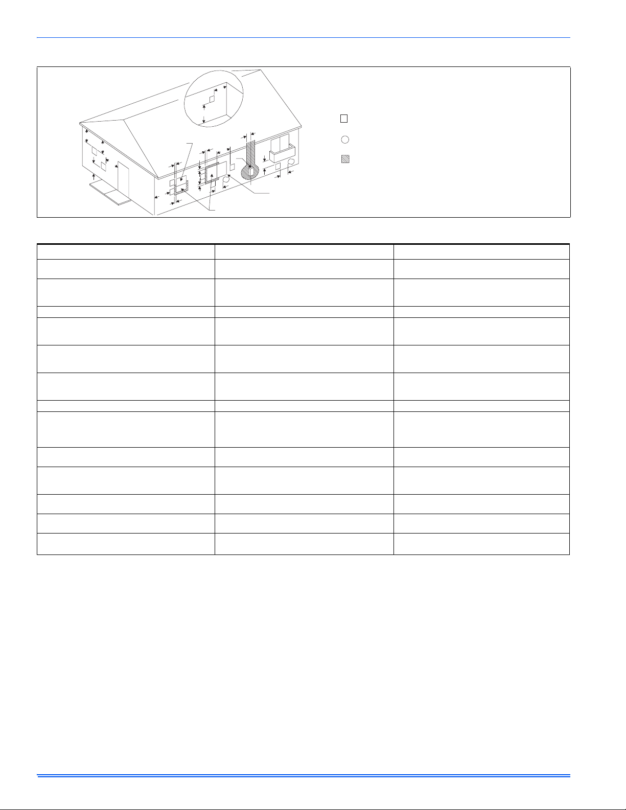
COMBUSTION AIR / VENT CLEARANCES
IMPORTANT: The vent must b e installed with the following minimum
clearances, and must comply with local codes and requirements.
Unitary Products Group 15
Page 16
292278-UIM-A-0108
VENT CLEARANCES
D
E
V
B
V
L
FIGURE 12: Home Layout
FIXED
CLOSED
C
V
V
F
B
A
B
V
B
G
V
B
B
I
V
X
V
J
OPERABLE
H
M
X
V
K
FIXED
CLOSED
V
VENT TERMINAL
X
AIR SUPPLY
AREA WHERE TERMINAL IS NOT PERMITTED
Direct Vent Terminal Clearances
A. Clearance above grade, veranda, porch, deck, or
balcony
B. Clearance to window or door that may be opened
Canadian Installations
1,3
US Installation
12 inches (30 cm) 12 inches (30 cm)
12 inches (30 cm) for models ≤100,000 BTUH (30 kW),
36 inches (91 cm) for models >100,000 BTUH (30 kW)
Two-pipe (direct vent) applic ations: 9 inches (23 cm)
for models ≤50,000 BTUH (15 kW), 12 inches (30 cm)
for models >50,000 BTUH (15 kW). ††
2,3
C. Clearance to permanently closed window 12 inches (30 cm) 12 inches (30 cm)
D. Vertical clearance to ventilated soffit located
above the terminal within a horizontal distance
of 2 feet (61 cm) from the center line of the terminal
E. Clearance to unventilated soffit
F. Clearance to outside corner
12 inches (30 cm) or in accordance with local
installation codes and the requirements of the gas
supplier.
12 inches (30 cm) or in accordance with local
installation codes and the requirements of the gas
supplier
12 inches (30 cm) or in accordance with local
installation codes and the requirements of the gas
supplier
12 inches (30 cm) or in accordance with local
installation codes and the requirements of t he gas supplier
12 inches (30 cm) or in accordance with local
installation codes and the requirements of the gas
supplier
12 inches (30 cm) or in accordance with local
installation codes and the requirements of the gas
supplier
G. Clearance to inside corner 3 feet (91 cm) 3 feet (91 cm)
H. Clearance to each side of center line
extended above meter/regulator assembly
Above a meter/regulator assembly within 3 feet (91 cm)
horizontally of the vertical center-line of the regulator
vent outlet to a maximum vertical distance of 15 feet
(4.5 cm) above the meter/regulator assembly.
I. Clearance to service regulator vent outlet 3 feet (91 cm)
J. Clearance to nonmechanical air supply inlet to
building or the combustion air inlet to any other
appliance
12 inches (30 cm) for models ≤100,000 BTUH (30 kW),
36 inches (91 cm) for models >100,000 BTUH (30 kW)
K. Clearance to a mechanical supply inlet 6 feet (1.83 m)
L. Clearance above paved sidewalk or paved
driveway located on public property
7 feet (2.13 m)†
M. Clearance under veranda, porch, deck, or balcony 12 inches (30 cm)‡
1. In accordance with the current CSA B149.1-00, Natural Gas and Propane Installation Code.
2. In accordance with the current ANSI Z223.1 / NFPA 54, National Gas Code.
3. In accordance with the current ANSI Z21.47 * CSA 2.3 American National Standard.
Above a meter/regulator assembly within 3 feet (91
cm) horizontally of the vertical center-line of the regulator vent outlet to a maximum vertical distance of 15
feet (4.5 cm) above the meter/regulator assembly.
3 feet (91 cm) or in accordance with local installation
codes and the requirements of the gas supplier.
Two-pipe (direct vent) applic ations: 9 inches (23 cm)
for models ≤50,000 BTUH (15 kW), 12 inches (30 cm)
for models >50,000 BTUH (15 kW).
3 feet (91 cm) above if within 10 feet (3 cm)
horizontally
7 feet (2.13 m) or in accordance with local installation
codes and the requirements of the gas supplier.
12 inches (30 cm) or in accordance with local installation codes and the requirements of the gas supplier
† A vent shall not terminate directly above a sidewalk or paved driveway that is located between two single family dwellings and serves both dwellings.
†† 12 inches (30 cm) up from the bottom edge of the structure for Two-pipe (direct vent) applications per ANSI Z223.1 / NFPA 54, National Gas Code.
‡ Permitted only if veranda, porch, deck, or balcony is fully o pen on a minimum of two sides beneath the fl oor and the distance between the top of the vent termination
and the underside of the veranda, porch, or deck is greater th an 1 foot (30 cm) as specified in CSA B149.1-00.
A vent shall not terminate less than 1 foot (30 cm) above a grade level.
Any fresh air or make up inlet for dryer or furnace area is considered to be forced air inlet.
Avoid areas where condensate drippage may cause problems such as above planters, patios, or adjacent to windows where steam may cause fogging.
A terminus of a vent shall be fitted with a cap in accordance with the vent manufacturer’s installation instructions, or in accordance with the installation instructions for a
special venting system.
IMPORTANT: Consideration must be given for degradation of building materials by flue gases. Sidewall termination may require sealing or shielding of building surfaces
with a corrosion resistant material to protect against combu stion product corrosion. Co nsideration must be given t o wind direct ion in o rder to prevent f lue pro duct s and/or
condensate from being blown against the building surfaces. If a metal shield is used it must be a stainless steel material at a minimum dimension of 20 inches. It is
recommended that a retaining type collar be used that is attached to the building surface to prevent movement of the vent pipe.
Responsibility for the provision of proper adequate venting and air supply for application shall rest with the installer.
Vent shall extend high enough above building, or a neighboring obstruction, so that wind from any direction will not create a positive pressure in the vicinity of the vent.
.
16 Unitary Products Group
Page 17
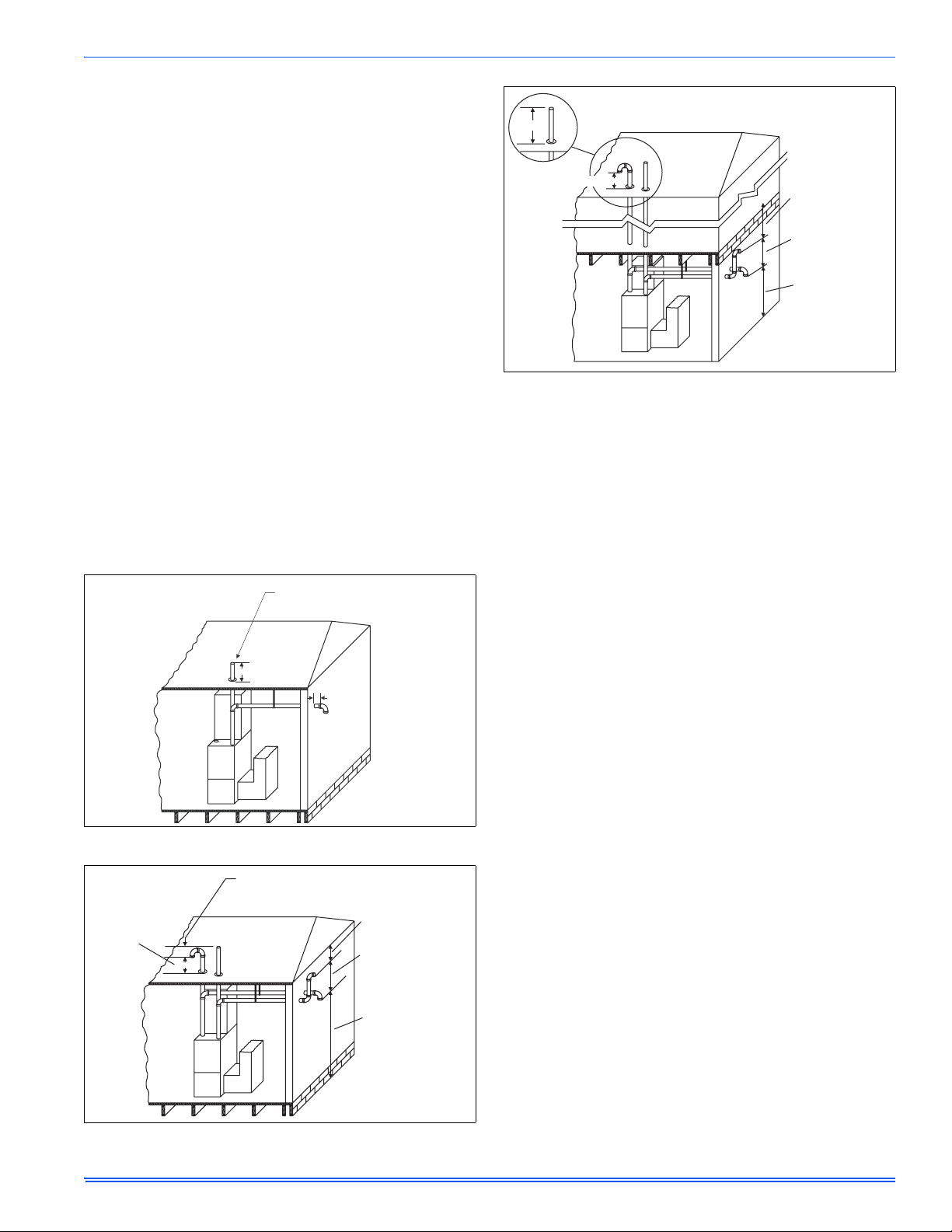
VENT SYSTEM
This furnace is certified to be installed with one of two possible vent
configurations.
1. Horizontal vent system. This vent system can be installed completely horizontal or combinations of horizontal, vertical, or offset
using elbows.
2. Vertical vent system. This vent system can be installed completely
vertical or a combination of horizontal, vertical, or offset using
elbows.
HORIZONTAL VENT APPLICATIONS AND
TERMINATION
When selecting the location for a horizontal combustion air / vent termination, the following should be considered:
1. Observe all clearances listed in vent clearances in these instructions.
2. Termination should be positioned where vent vapors will n ot damage plants or shrubs or air conditioning equipment.
3. Termination should be located where it will not be affected by wind
gusts, light snow, airborne leaves or allow recirculation of flue
gases.
4. Termination should be located where it will not be damaged or
exposed to flying stones, balls, etc.
5. Termination should be positioned where vent vapors are not objectionable.
6. Horizontal portions of the vent system must slope upwards and be
supported to prevent sagging.
7. Sealed combustion air systems must be installed so the vent and
the combustion air pipes terminate in the same atmospheric zone.
Refer to Figures 14 or 15.
MAINTAIN 12” MINIMUM CLEARANCE
ABOVE HIGHEST ANTICIPATED SNOW
LEVEL. MAXIMUM 24” ABOVE ROOF.
12” MIN.
12” MIN.
FIGURE 13: Termination Configuration - 1 Pipe
12” VERTICAL SEPARATION
BETWEEN COMBUSTION AIR
AND VENT
MAINTAIN 12”
MINIMUM
CLEARANCE
ABOVE
HIGHEST
ANTICIPATED
SNOW LEVEL
12” MINIMUM
BELOW OVERHANG
12” SEPARATION
BETWEEN BOTTOM
OF COMBUSTION
AIR PIPE AND
BOTTOM OF VENT
MAINTAIN 12”
MINIMUM CLEARANCE
ABOVE HIGHEST
ANTICIPATED SNOW
LEVEL OR GRADE,
WHICHEVER IS
HIGHER
292278-UIM-A-0108
12” MIN.
12” MIN.
OVERHANG
12” MINIMUM
BELOW
OVERHANG
12” SEPARATION
BETWEEN BOTTOM
OF COMBUSTION
AIR PIPE AND
BOTTOM OF VENT
MAINTAIN 12”
MINIMUM
CLEARANCE
ABOVE HIGHEST
ANTICIPATED SNOW
LEVEL OR GRADE,
WHICHEVER IS
HIGHER
FIGURE 15: Termination Configuration - 2 Pipe Basement
VERTICAL VENT APPLICATIONS AND
TERMINATION
Roof mounted vertical terminals may be field fabricated. Standard PVC/
SRD fittings may be used. If installing a vertical venting system through
any unconditioned space such as an attic or crawl space it must be
insulated.
1. Observe all clearances listed in vent clearances in these instructions.
2. Termination should be positioned where vent vapors are not objectionable.
3. Termination should be located where it will not be affected by wind
gusts, light snow, or allow recirculation of flue gases.
4. Termination should be located where it cannot be damaged,
plugged or restricted by tree limbs, leaves and branches.
5. Horizontal portions of the vent system must slope upwards and be
supported to prevent sagging.
6. Sealed combustion air systems must be installed so the vent and
the combustion air pipes terminate in the same atmospheric zone.
Refer to Figures 14 or 15.
VENTING MULTIPLE UNITS
Multiple units can be installed in a space or structure as either a single
pipe configuration or a two-pipe configuration.
The combustion air side of the single pipe configuration shown in Figure
19 is referred to in these instructions as ambient combustion air supply.
Follow the instructions for ambient combustion air installations, paying
particular attention to the section on air source from inside the building.
The vent for a single pipe system must be installed as specified in the
venting section of these instructions with the vent terminating as shown
in Figure 13. Each furnace must have a separate vent pipe. Under NO
circumstances can the two vent pipe be tied together.
The combustion airside of the two-pipe configuration shown in Figure
18 can be installed so the combustion air pipe terminates as described
in outdoor combustion air or ventilated combustion air sections in these
instructions. Follow the instructions for outdoor combustion air or ventilated combustion air and the instructions for installing the vent system
with the vent terminating as shown in Figures 16 or 17. The two-pipe
system must have a separate combustion air pipe and a separate vent
pipe for each furnace. Under NO circumstances can the two combustion air or vent pipes be tied together. The combustion air and vent
pipes must terminate in the same atmospheric zone.
FIGURE 14: Termination Configuration - 2 Pipe
Unitary Products Group 17
Page 18
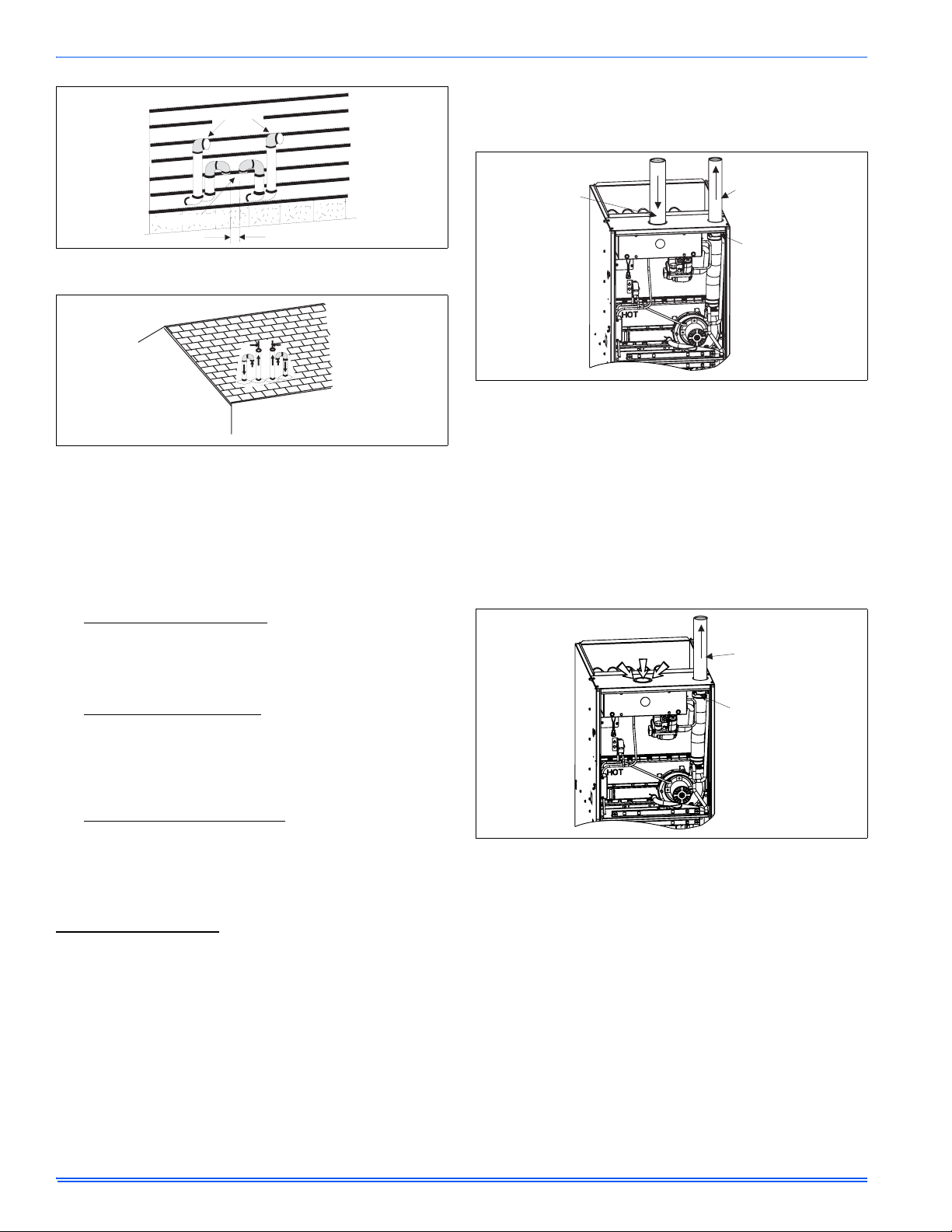
292278-UIM-A-0108
VENT
COMBUSTION AIR
2”
FIGURE 16: Double Horizontal Sealed Combustion Air and Vent
Termination
6”
FIGURE 17: Double Vertical Sealed Combustion Air and Vent
Termination
COMBUSTION AIR SUPPLY
All installations must comply with Section 5.3, Air for Combustion and
Ventilation of the National Fuel Gas Code, ANSI Z223.1 or Sections
7.2, 7.3 or 7.4 of CAN/CGA B149.1 or .2 Installation Code - latest editions.
This furnace is certified to be installed with one of three possible combustion air intake configurations.
1. OUTDOOR COMBUSTION AIR:
This is a sealed combustion air
configuration where the combustion air is supplied through a PVC
or ABS pipe that is connected to the PVC coupling attached to the
burner box and is terminated in the same atmospheric zone as the
vent. This type of installation is approved on all models. Refer to
Figure 18.
2. AMBIENT COMBUSTION AIR:
Combustion air is supplied from
the area surrounding the furnace through vents or knockouts in the
furnace casing. The combustion air and the vent pipes are not terminated in the same atmospheric zone. Refer to Figure 13 for vent
terminations. Refer to “AIR SOURCE FROM INSIDE THE BUILDING” and “VENT AND SUPPLY AIR SAFETY CHECK” for proper
installation. Refer to Figure 19.
3. VENTILATED COMBUSTION AIR:
Combustion air is supplied
through a PVC or ABS pipe that is connected to the PVC coupling
attached to the burner box and is terminated in a ventilated attic or
crawl space. The combustion air and the vent pipes are not terminated in the same atmospheric zone. Refer to Figure 21 for attic
and crawl space termination. Only the combustion air intake may
terminate in the attic. The vent must terminate outside.
Outdoor Combustion Air
Combustion Air Intake/Vent Connections
This installation requires combustion air to be brought in from outdoors.
This requires a properly sized pipe (Shown in Figure 18) that will bring
air in from the outdoors to the furnace combustion air intake collar on
the burner box. The second pipe (Shown in Figure 18) is the furnace
vent pipe.
The combustion air intake pipe should be located either through the
wall (horizontal or side vent) or through the roof (vertical vent). Care
should be taken to locate side vented systems where trees or shrubs
will not block or restrict supply air from entering the terminal.
Also, the terminal assembly should be located as far as possible from a
swimming pool or a location where swimming pool chemicals might be
stored. Be sure the terminal assembly follows the outdoor clearances
listed in Section #1 “Outdoor Air Contaminants.”
VENT PIPE CEMENTS
CONNECTS TO
COLLAR ON TOP
OF BURNER BOX
INTO SOCKET JUST
ABOVE TOP PANEL
OR VENT PIPE MAY
BE CLAMPED INTO
OUTLET OF DRAIN
COUPLING
FIGURE 18: Sealed Combustion Air Intake Connection and Vent
Connection
Ambient Combustion Air Supply
This type installation will draw the air required for combustion from
within the space surrounding the appliance and from areas or rooms
adjacent to the space surrounding the appliance. This may be from
within the space in a non-confined location or it may be brought into the
furnace area from outdoors through permanent openings or ducts. It is
not piped directly into the burner box. A single, properly sized pipe from
the furnace vent connector to the outdoors must be provided. For
upflow models combustion air is brought into the furnace through the
unit top panel opening. Do not install a pipe into the intake collar on top
of the burner box. Refer to Figure 19.
COMBUSTION AIR
FIGURE 19: Combustion Airflow Path Through The Furnace Casing
An unconfined space is not less than 50 cu.ft (1.42 m
hr (0.2928 kW) input rating for all of the appliances installed in that
area.
Rooms communicating directly with the space containing the appliances are considered part of the unconfined space, if openings are not
furnished with doors.
A confined space is an area with less than 50 cu.ft (1.42 m
Btu/hr (0.2928 kW) input rating for all of the appliances installed in that
area. The following must be considered to obtain proper air for combustion and ventilation in confined spaces.
VENT PIPE CEMENTS
INTO SOCKET JUST
ABOVE TOP PANEL
OR VENT PIPE MAY
BE CLAMPED INTO
OUTLET OF DRAIN
COUPLING
3
) per 1,000 Btu/
3
) per 1,000
18 Unitary Products Group
Page 19
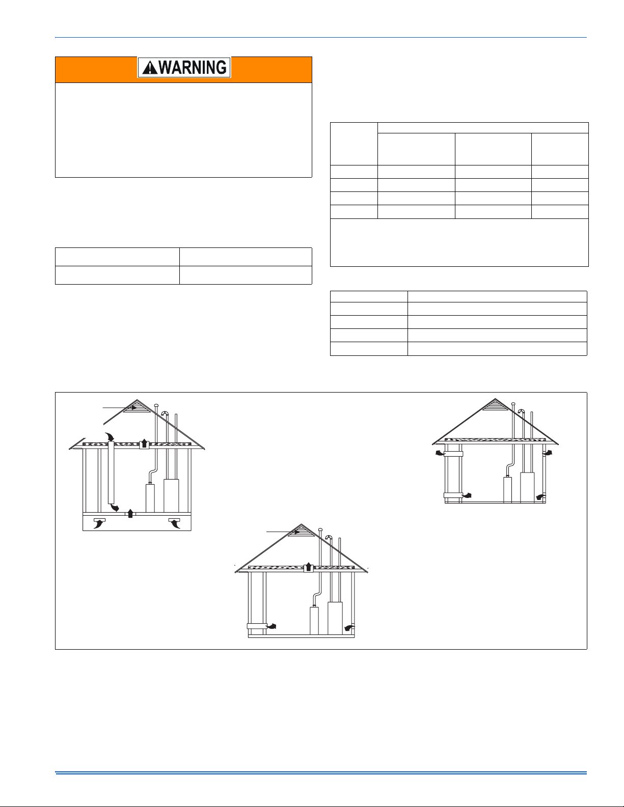
This type of installation requires that the supply air to the appliance(s) be of a sufficient amount to support all of the appliance(s)
in the area. Operation of a mechanical exhaust, such as an exhaust
fan, kitchen ventilation system, clothes dryer or fireplace may create conditions requiring special attention to avoid unsatisfactory
operation of gas appliances. A venting problem or a lack of supply
air will result in a hazardous condition, which can cause the appliance to soot and generate dangerous levels of CARBON MONOXIDE, which can lead to serious injury, property damage and / or
death.
Combustion Air Source From Outdoors
The blocking effects of louvers, grilles and screens must be given consideration in calculating free area. If the free area of a specific louver or
grille is not known, refer to Table 10, to estimate free area.
TABLE 10:
* Do not use less than 1/4” (0.635 cm) mesh.
+ Free area or louvers and grille varies widely; the installer should follow lou-
Estimated Free Area
Wood or Metal
Louvers or Grilles
Screens+
ver or grille
manufacturer’s instructions.
Wood 20-25%*
Metal 60-70% *
1/4” (0.635 cm)
mesh or larger 100%
Dampers, Louvers and Grille s (C anada Only)
1. The free area of a supply air opening shall be calculated by sub-
tracting the blockage area of all fixed louvers grilles or screens
from the gross area of the opening.
2. Apertures in a fixed louver, a grille, or screen shall have no dimen-
sion smaller than 0.25” (6.4 mm).
292278-UIM-A-0108
3. A manually operated damper or manually adjustable louvers are
not permitted for use.
4. A automatically operated damper or automatically adjustable louvers shall be interlocked so that the main burner cannot operate
unless either the damper or the louver is in the fully open position.
TABLE 11:
60,000
80,000
100,000
120,000
EXAMPLE: Determining Free Area.
Appliance 1Appliance 2Total Input
100,000 + 30,000 = (130,000 ÷ 4,000) = 32.5 Sq. In. Vertical
Appliance 1Appliance 2Total Input
100,000 + 30,000 = (130,000 ÷ 2,000) = 65 Sq. In. Horizontal
TABLE 12:
BTUH Input Rating Minimum Free Area Required for Each Opening
BTUH
Input
Rating
60,000
80,000
100,000
120,000
Free Area
Minimum Free Area Required for Each Opening
Horizontal Duct
(2,000 BTUH)
30 sq. in. (194 cm
40 sq. in. (258 cm
50 sq. in. (323 cm
60 sq. in. (387 cm
Vertical Duct or
Opening to Outside
(4,000 BTUH)
2
) 15 sq. in. (97 cm2) 5” (13 cm2)
2
) 20 sq. in. (129 cm2) 5” (13 cm2)
2
) 25 sq. in. (161 cm2) 6” (15 cm2)
2
) 30 sq. in. (194 cm2) 7” (18 cm2)
Unconfined Space Minimum Area in Square Inch
60 (387 cm
80 (516 cm
100 (645 cm
120 (774 cm
2
)
2
)
2
)
2
)
Round Duct
(4,000 BTUH)
GABLE
VENT
VENTILATED
OPTIONAL
INLET (a)
SOFFIT
VENT
5. Asquare or rectangular shaped duct shall only be used
when the required free area of the supply opening is
22
9 in (58.06 cm ) or larger. When a square or rectangular
duct is used, its small dimensionshall not be less than
3 in (7.6 cm).
6. An air inlet supply from outdoors shall be equipped with
a means to prevent the direct entry of rain and wind.
Such means shall not reduce the required free area of
the air supply opening.
7. An air supply inlet opening from the outdoors shall
be located not less than 12” (30.5 cm) above the
outside grade level.
ATTIC
TOP ABOVE
INSULATION
OUTLET
AIR (a)
GAS
WATER
HEATER
VENTILATED
CRAWL SPACE
GAS
VENT
FURNACE
AIR SUPPLY OPENINGS AND DUCTS
An opening may be used in lieu of a duct to provide to provide the outside air
1.
supply to an appliance unless otherwise permitted by the authority having
jurisdiction. The opening shall be located within 12” (30.5 cm) horizontally from,
the burner level of the appliance. Refer to “AIR SOURCE FROM OUTDOORS
AND VENT AND SUPPLY AIR SAFETY CHECK” in these instructions for
additional information and safety check procedure.
The duct shall be either metal, or a material meeting the class 1
2.
requirements of CAN4-S110 Standard for Air Ducts.
The duct shall be least the same cross-sectional area as the free
3.
area of the air supply inlet opening to which it connects.
The duct shall terminate within 12 in (30.5 cm) above, and
4.
within 24 in (61 cm) horizontally from, the burner level of
the appliance having the largest input.
SOFFIT
VENT
INLET
AIR (b)
FIGURE 20: Outside and Ambient Combustion Air
GABLE
VENT
VENTILATED
ATTIC
TOP ABOVE
INSULATION
GAS
WATER
HEATER
GAS
VENT
FURNACE
OUTLET
AIR (b)
GAS
WATER
INLET
AIR (b)
COMBUSTION AIR SOURCE FROM OUTDOORS
Two permanent openings, one within 12 in (30.5 mm) of the top and
1.
INLET
AIR (a)
one within 12 in (30.5 mm) of bottom of the confined space,
permanent openings,
with the outdoors, crawl spaces or attic spaces.
One permanent openings, commencing within 12 in (30.5 mm)of the
2.
top of the enclosure shall be permitted where the equipment has
clearances of at least 1 in (2.54 cm) from the sides and back and
6 in (15.24 cm) from the front of the appliance. The opening shall
communicate directly with the outdoors and shall have a minimum
free area of:
a.
1 square in per 3000 Btu per hour (6.45 0.879 kW) of the
total input rating of all equipment located in the enclosure.
b.
Not less than the sum of all vent connectors in the confined space.
3.
The duct shall be least the same cross-sectional area as the free
area of the air supply inlet opening to which it connects.
4.
The blocking effects of louvers, grilles and screens must be given
consideration in calculating free area. If the free area of a specific
louver aor grille is not known.
shall communicate directly or by means of ducts
HEATER
GAS
VENT
3
cm per
FURNACE
OUTLET
AIR (a)
INLET
AIR (a)
Two
Unitary Products Group 19
Page 20
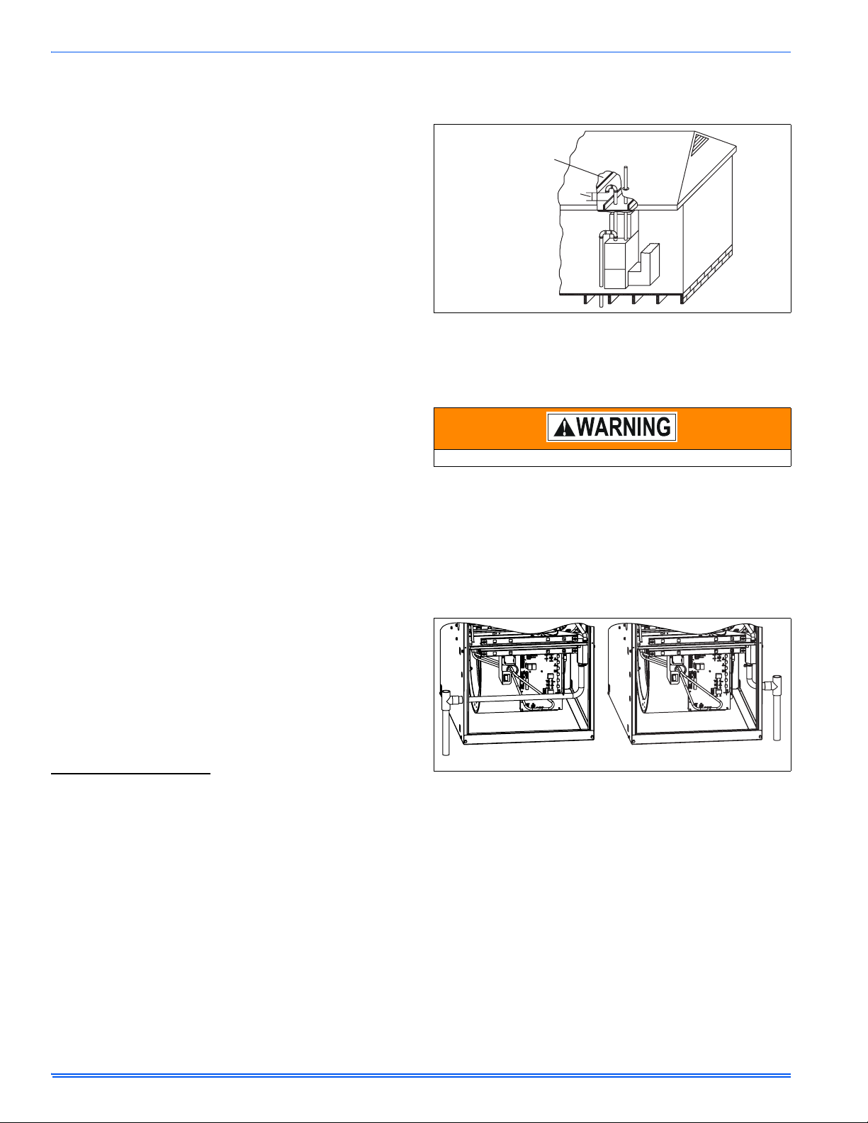
292278-UIM-A-0108
Vent and Supply (Outside) Air Safety Check Procedure
Follow the procedure in ANSI Z223.1 National Fuel Gas Code. Refer to
the section on the “Recommended Procedure for Safety Inspection of
an Existing Appliance” or in Canada B149.1-00 Natural Gas and Propane Installation Code section on “Venting Systems and Air Supply for
Appliances” and all local codes. In addition to the procedure specified in
ANSI Z223.1, It is recommended that you follow the venting safety procedure below. This procedure is designed to detect an inadequate ventilation system that can cause the appliances in the area to operate
improperly causing unsafe levels of Carbon Monoxide or an unsafe
condition to occur.
1. Inspect the venting system for proper size and horizontal pitch.
Determine that there is no blockage, restriction, leakage, corrosion
or other deficiencies, which could cause an unsafe condition
2. Close all building doors and windows and all doors.
3. Turn on clothes dryers and TURN ON any exhaust fans, such as
range hoods and bathroom exhausts, so they shall operate at
maximum speed. Open the fireplace dampers. Do not operate a
summer exhaust fan.
4. Follow the lighting instructions. Place the appliance being
inspected in operation. Adjust thermostat so the appliance shall
operate continuously.
5. Test each appliance (such as a water heater) equipped with a draft
hood for spillage (down-draft or no draft) at the draft hood relief
opening after 5 minutes of main burner operation. Appliances that
do not have draft hoods need to be checked at the vent pipe as
close to the appliance as possible. Use a combustion analyzer to
check the CO2 and CO levels of each appliance. Use a draft
gauge to check for a downdraft or inadequate draft condition.
6. After it has been determined that each appliance properly vents
when tested as outlined above, return doors, windows, exhaust
fans, fireplace dampers and any other gas burning appliance to
their normal condition.
7. If improper venting is observed during any of the above tests, a
problem exists with either the venting system or the appliance
does not have enough combustion air (Supply Air from outside) to
complete combustion. This condition must be corrected before the
appliance can function safely.
NOTE: An unsafe condition exists when the CO reading exceeds 100
ppm and the draft reading is not in excess of - 0.1 in. W.C. (-25 kPa)
with all of the appliance(s) operating at the same time.
8. Any corrections to the venting system and / or to the supply (outside) air system must be in accordance with the National Fuel Gas
Code Z223.1 or CAN/CGA B149.1-00 Natural Gas and Propane
Installation Code (latest editions). If the vent system must be
resized, follow the appropriate tables in Appendix G of the above
codes or for this appliance only refer to Table 6 of these instructions.
Ventilated Combustion Air
The ventilated attic space or a crawl space from which the combustion
air is taken must comply with the requirements specified in “AIR
SOURCE FROM OUTDOORS” in this instruction or in Section 5.3, Air
for Combustion and Ventilation of the National Fuel Gas Code, ANSI
Z223.1 (latest edition). This type installation requires two properly sized
pipes. One brings combustion air from a properly ventilated attic space
or crawl space and a second pipe that extends from the furnace vent
connection (top right of unit) to the exterior of the building. Refer to
Table 6 for intake pipe sizing, allowable length and elbow usage. Follow
all notes, procedures and required materials in the SEALED COMBUSTION AIR SUPPLY section in these instructions when installing the
combustion air pipe from the unit and into a ventilated attic space or
crawl space. DO NOT terminate vent pipe in an Attic or Crawl Space.
Ventilate d Combus tio n Air Termination
Refer to Figure 21 for required attic termination for the combustion air
intake pipe. For attic termination, use two 90 elbows with the open end
in a downward position. Be sure to maintain 12” (30 cm) clearance
above any insulation, flooring or other material.
A crawl space combustion air installation consists of a straight pipe from
the PVC coupling on the burner box that extends into the crawl space
and terminates with a 1/4” (6.35 mm) mesh screen and no elbows.
12” MINIMUM
BETWEEN BOTTOM
OF BELOW AND
ANY MATERIAL
12”
MIN.
FIGURE 21: Attic and Crawl Space Combustion Air Termination
Specially Engineered Installations
The above requirements shall be permitted to be waived where special
engineering, approved by the authority having jurisdiction, provides an
adequate supply of air for combustion and ventilation.
Be sure to instruct the owner not to block this intake pipe.
SECTION VIII: CONDENSATE PIPING
The condensate drain connection is provided in the furnace for field
installation. It consists of a formed hose with a 1/2” (1.3 cm) NPT male
connection. A 1/2” (1.3 cm) FM x 3/4” (1.9 cm) PVC slip coupling is provided.
This drain hose may be installed to allow left or right side condensate
drain connection, refer to Figure 20. Cut the hose to allow for proper fit
for left or right exit. If necessary, trim the hose supplied to ensure that it
slopes downwards.
LH DRAIN
FIGURE 22: Condensate Piping
To install the drain hose assembly, remove the 7/8” (2.2 cm) knockout in
the side panel. Remove the conduit nut from the 1/2” (1.3 cm) male fitting. Push the male fitting through the hole and reinstall the nut. The
use of the 3/4” (1.9 cm) PVC coupling is optional.
The condensate water will flow to the drain better if an open tee, or
short length of pipe is installed in the drain line, as shown in Figure 20.
IMPORTANT: The condensate drain from the furnace may be connected in common with the drain from an air conditioning coil if allowed
by local code.
IMPORTANT: Condensate must be disposed of properly. Follow local
plumbing or wastewater codes. The drain line must maintain a 1/4" per
foot (0.635 cm per meter) slope to the drain.
RH DRAIN
20 Unitary Products Group
Page 21
292278-UIM-A-0108
CONDENSATE DRAIN
The condensate trap must be filled with water before putting the furnace
into operation. Perform the following procedures only after the condensate trap has been properly piped to a drain connection using the procedure in this instruction.
The recommended procedure is as follows:
1. Disconnect the condensate drain hose from the induced draft
blower discharge.
2. Elevate this hose and fill with water using a funnel.
3. Replace the condensate drain hose and clamps.
IMPORTANT: If this procedure is not followed, the unit may not properly
drain on initial start up.
CONDENSATE DRAIN TERMINATION
DO NOT terminate condensate drain in a chimney, or where the drain
line may freeze. The line must terminate at an inside drain to prevent
freezing of the condensate and possible property damage.
DO NOT trap the drain line at any other location than at the condensate
drain trap supplied with the furnace.
A condensate sump pump MUST be used if required by local codes, or
if no indoor floor drain is available. The condensate sump pump must
be approved for use with acidic condensate.
CONDENSATE DRAIN TRAP AND DRAIN FREEZE
PROTECTION
Special precautions MUST be made if installing furnace in an area
which may drop below freezing. This can cause improper operation or
damage to the equipment. If the furnace is installed in an area that has
the potential of freezing, the drain line and the drain trap must be protected. Use a 3 to 6 watt per foot at 115 vac, 40º F (4.4° C) self-regulating, shielded and waterproof heat tape. Wrap the drain trap and the
drain line with the heat tape and secure with ties. Follow the heat tape
manufacturer's recommendations.
SECTION IX: SAFETY CONTROLS
CONTROL CIRCUIT FUSE
A 3-amp fuse is provided on the control circuit board to pr otect the 24volt transformer from overload caused by control circuit wiring errors.
This is an ATO 3, automotive type fuse and is located on th e control
board.
BLOWER DOOR SAFETY SWITCH
This unit is equipped with an electrical interlock switch mounted in the
blower compartment. This switch interrupts all power at the unit when
the panel covering the blower compartment is removed.
Electrical supply to this unit is dependent upon the panel that covers the
blower compartment being in place and properly positioned.
Main power to the unit must still be interrupted at the main power
disconnect switch before any service or repair work is to be done to
the unit. Do not rely upon the interlock switch as a main power disconnect.
Blower and burner must never be operated without the blower
panel in place.
ROLLOUT SWITCH CONTROLS
These controls are mounted on the burner box assembly. If the temperature in the burner box exceeds its set point, the ignition control and the
gas valve are de-energized. The operation of this control indicates a
malfunction in the combustion air blower, heat exchanger or a blocked
vent pipe connection. Corrective action is required. These are manual
reset controls that must be reset before operation can continue.
PRESSURE CONTROLS
Pressure Sensor - This furnace is equipped with a pressure sensor
mounted on the furnace control board. This sensor monitors combustion airflow through furnace and piping systems. If any of the conditions
listed above are detected by the pressure sensor, the control board will
prevent a hazardous condition from occurring by speeding up the combustion blower motor in order to maintain adequate combustion airflow.
If the combustion blower is already turning at full speed, the furnace
control will then start reducing the input to the furnace in order to maintain proper combustion with the amount of combustion airflow available.
If there is not enough combustion air available to give proper combustion even at the minimum input rate (35%), the control will close the gas
valve and shut off the burners.
Pressure Switch - This furnace is equipped with a pressure switch
mounted on the furnace vestibule panel. This switch monitors the flow
through the combustion air/vent system. The switch will close at the
beginning of each cycle when adequate combustion airflow is established. However, this switch may be open under certain conditions
when the burners are lit. The pressure sensor is the primary flow sensor.
1. Blockage of combustion air piping
2. Blockage of vent piping or vent terminal
3. Failure of combustion air blower motor or blower wheel.
4. Blockage of condensate drain piping.
LIMIT CONTROLS
Limit Switch - This furnace is equipped with a high temperature limit
control mounted to the left side of the furnace vestibule panel. This limit
switch will open and shut off gas to the burners if it detects excessive air
temperature in the furnace, which can be caused by any of the following
conditions:
1. Dirty filter
2. Failure of the circulating blower motor or wheel
3. Too many supply or return registers closed or blocked.
Temperature Sensor - This furnace is also equipped with a tempera-
ture sensor mounted to the right side of the vestibule panel, near the
top of the furnace. This sensor monitors the temperature of the air being
supplied to the home. If the sensor detects air temperature higher than
its setting, the furnace control will first speed up the circulating blower
motor in order to try to increase the amount of airflow being delivered,
thereby reducing the air temperature. If the blower motor is already
turning at full speed, the control will then start reducing the input to the
furnace to try to reduce the air temperature. If the supply air temperature is too high even at the minimum input rate (35%), the control will
close the gas valve and shut off the furnace.
SECTION X: START-UP AND
ADJUSTMENTS
NOTE: In order that this furnace will operate properly, it is required that
all of the startup procedures in this section be followed:
Perform the following procedures only after the condensate trap
has been properly piped to a drain connection using the procedure
in this instruction.
Unitary Products Group 21
Page 22
292278-UIM-A-0108
TOOLS AND INFORMATION THAT WILL BE
REQUIRED IN ORDER TO PROPERL Y PERFORM THE
FURNACE STARTUP PROCEDURE.
1. Call the local gas supplier to obtain heating value of the natural
gas. If you cannot obtain the heating valve of the gas from the gas
supplier, you may use a default value of 1030 BTU/SCF (38.8 MJ /
m³).
2. You will need a thermometer or portable digital thermometer to
read the supply and return air temperatures.
3. You will need a U-tube manometer or digital equipment that has
the ability to read pressures between 0 – 15” in.w.c (0 - 3.73 kPa)
in order to measure the gas line and the manifold pressures.
4. You will need a 3/16” Allen wrench for the pressure port plugs in
the gas valve.
5. You will need 2 pieces of 1/8” (0.3 cm) ID flexible tubing that is 12”
(30 cm) in length, 2 – pieces of 1/8” (0.3 cm) tubing that are 4”
(10.0 cm) in length, a 1/8” (0.3 cm) tee and a 1/8” (0.3 cm) adapter
to connect the U-tube manometer or the digital pressure measuring equipment to the gas valve pressure ports.
There is an accessory kit (1PK0601) available from Source 1, which
has the following items:
• 1 - 12” (30 cm) length x 1/8” (0.3 cm) diameter tubing
• 2 – pieces of 4” (10 cm) length x 1/8” (0.3 cm) diameter tubing
• 1 - 5/16” (0.8 cm) tee
• 1 – 5/16” (0.8 cm) x 1/8” (3.175 mm) reducing coupling
• 1 – 1/8” (0.3 cm) adapter
There is a accessory kit (1PK0602) available from Source 1, which has
the following items:
• 12” (30 cm) length x 1/8” (0.3 cm) diameter tubing
• 2 – pieces of 4” (10 cm) length x 1/8” (0.3 cm) diameter tubing
• 1 - 5/16” (0.8 cm) tee
• 1 – 5/16” (0.8 cm) x 1/8” (0.3 cm) reducing coupling
• 1 – 1/8” (0.3 cm) adapter
• 1 - Dwyer – Manometer
These items are required in order to properly perform the required startup procedure.
GAS PIPING LEAK CHECK
FIRE OR EXPLOSION HAZARD
Failure to follow the safety warnings exactly could result in serious
injury, death or property damage.
Never test for gas leaks with an open flame. Use a commercially
available soap solution made specifically for the detection of leaks
to check all connections. A fire or explosion may result causing
property damage, personal injury or loss of life.
IMPORTANT: Burner ignition may not be satisfactory on first startup
due to residual air in the gas line or until gas manifold pressure is
adjusted. The ignition control will make three attempts to light before
locking out.
It is recommended that when the gas supply is first connected to the
furnace, the ground union be loosened until the odor of gas is detected.
When gas is detected, immediately tighten the union and check for gas
leaks. Allow five minutes for any gas to dissipate before continuing with
the startup procedure. Be sure that proper ventilation is available to
dilute and carry away any vented gas.
With furnace in operation, check all of the pipe joints, gas valve connections and manual valve connections for leakage using an approved gas
detector, a non-corrosive leak detection fluid or other leak detection
methods. Take appropriate action to stop any leak. If a leak persists,
replace the faulty component.
The furnace and its equipment shutoff valve must be disconnected from
the gas supply during any pressure testing of that system at test pressures in excess of 1/2 PSI (3.45 kPa).
The furnace must be isolated from the gas supply piping system by
closing the equipment shutoff valve during any pressure testing of the
gas supply system.
SETUP TEST MODE
During normal operation, the furnace input rate can vary between 35%
and 100% of full nameplate input, making it difficult to check for proper
operation. To help with the furnace startup process, the control has a
TEST MODE available that allows the furnace input rate to stay at a
constant input rate. To access this TEST MODE perform the following
sequence:
1. With power to the board on and with no thermostat calls (no call for
heating, cooling or continuous fan), push and hold the TEST button on the board for one second. The LED on the board will glow
red.
2. Release the TEST button. The LED on the board will flash a rapid
green signal, indicating that TEST MODE is activated.
3. Turn the thermostat to call for heat (R & W signal).
4. The furnace will light and operate at high (100%) firing rate. The
furnace firing rate should be checked at this level to confirm that
the furnace is not overfired or underfired.
5. To run the furnace at minimum rate (35%), press the ERROR button once. The LED will flash one green flash to confirm.
6. To run the furnace at a middle rate (70%), press the ERROR button twice within a five-second period. The LED will flash green two
times to confirm.
7. To again operate the furnace at maximum (100%) r ate, press the
ERROR button three times within a five-second period. The LED
will flash green three times to confirm.
8. If the thermostat call for heat is removed, the LED will flash a rapid
green signal, indicating that the furnace is still in TEST MODE.
9. When startup tests are completed, turning off power to the board
will take the furnace out of TEST MODE and will restore normal
operation. The furnace will automatically return to normal operation after 150 minutes if power is not cycled.
CALCULATING THE FURNACE INPUT
(NATURAL GAS)
NOTE: Burner orifices are sized to provide proper input rate using natural gas with a heating value of 1030 BTU/Ft
ing value of your gas is significantly different, it may be necessary to
replace the orifices.
NOTE: Front door of burner box must be secured when checking gas
input.
1. Turn off all other gas appliances connected to the gas meter.
2. At the gas meter, measure the time (with a stop watch) it takes to
use 2 cubic ft. (0.0566 m
3. Calculate the furnace input by using one of the following equations.
3
.) of gas.
3
(38.4 MJ/m3). If the heat-
22 Unitary Products Group
Page 23
292278-UIM-A-0108
In the USA use the following formula to calculate the furnace input.
For natural gas multiply the heat content of the gas BTU/SCF or Default 1030 BTU/SCF (38.4 MJ/m
the gas meter, times a barometric pressure and temperature correction factor of 0.960; times 3600, then divided by the time (In seconds) it took to
measure 2 cubic ft. (0.056 m) of gas from the gas meter.
For propane (LP) gas multiply the heat content of the gas BTU/SCF or Default 2500 BTU/SCF (93.15 MJ/m
sured at the gas meter, times a barometric pressure and temperature correction factor of 0.960; times 3600, then divided by the time (In seconds) it
took to measure 1 cubic ft. (0.028 m) of gas from the gas meter.
The formula for US input calculation using a cubic foot gas meter:
BTU/ft3 x 2 cu.ft. x 0.960 x 3600
Seconds it took to measure the 2 cu.ft. of gas Seconds it took to measure the 1 cu.ft. of ga s
NATURAL GAS INPUT CALCULATION PROPANE (LP) GAS INPUT CALCULATION
EXAMPLE: EXAMPLE:
1030 x 2 x 0.960 x 3600
90.5 108
Natural Gas Propane Gas
1030 BTU/SCF 2500 BTU/SCF
=BTU/H
= 78,666.90
BTU/ft3 x 1 cu.ft. x 0.960 x 3600
2500 x 1 x 0.960 x 3600
In Canada you will use the following formula to calculate the furnace input if you are using a cubic foot gas meter.
3
For Natural Gas multiply the Heat content of the gas MJ/m
(or Default 38.4), times 2 cubic ft. of gas x 0.028 to convert from cubic feet to cubic
meters measured at the gas meter, times a barometric pressure and temperature correction factor of 0.960; times 3600, then divided by the time it
took to measure 2 cubic ft. (0.056 m) of gas from the gas meter.
3
For Propane (LP) Gas multiply the Heat content of the gas MJ/m
(or Default 93.15), times 1 cu. ft. of gas x 0.028 to convert from cubic feet to cubic
meters measured at the gas meter, times a barometric pressure and temperature correction factor of 0.960; times 3600, then divided by the time it
took to measure 1 cubic ft. (0.028 m) of gas from the gas meter.
The formula for metric input calculation using a cubic foot gas meter:
3
x 2 cu.ft. x 0.028 x 0.960 x 3600
MJ/m
Seconds it took to measure the 2 cu.ft . of gas
NATURAL GAS INPUT CALCULATION
EXAMPLE:
38.4 x 2 x 0.028 x 0.960 x 3600
Natural Gas
1030 BTU/SCF = 38.4 MJ/m
PROPANE (LP) GAS INPUT CALCULATION
EXAMPLE:
93.15 x 1 x 0.028 x 0.960 x 3600
Propane Gas
2500 BTU/SCF = 93.15 MJ/m
90.5
3
108
3
= MJ/H x 0.2777 = kW x 3412.14 = BTU/H
= 82.12 x 0.2777 = 22.80 x 3412.14 = 77,796.80
= 83.46 x 0.2777 = 23.18 x 3412.14 = 79,093.4
In Canada use the following formula to calculate the furnace input if you are using a gas meter that measures cubic meters.
3
For Natural Gas multiply the Heat content of the gas MJ/m
(or Default 38.4), times 0.10 m3 of gas measured at the gas meter, times a barometric
pressure and temperature correction factor of 0.960; times 3600, then divided by the time it took to measure 0.10 m
3
For Propane (LP) Gas multiply the Heat content of the gas MJ/m
(or Default 93.15), times 0.10 m3 of gas measured at the gas meter, times a barometric pressure and temperature correction factor of 0.960; times 3600, then divided by the time it took to measure 0.10 m
meter.
The formula for metric input calculation using a cubic foot gas meter:
MJ/m3 x m3 x 0.960 x 3600
Seconds it took to measure the 0.10
NATURAL GAS INPUT CALCULATION
EXAMPLE:
38.4 x 0.1 x 0.960 x 3600
160
Natural Gas
1030 BTU/SCF = 38.4 MJ/m
PROPANE (LP) GAS INPUT CALCULATION
EXAMPLE:
93.15 x 0.1 x 0.960 x 3600
387
Propane Gas
2500 BTU/SCF = 93.15 MJ/m
m
3
3
of gas
3
= MJ/H x 0.2777 = kW x 3412.14 = BTU/H
= 82.94 x 0.2777 = 23.03 x 3412.14 = 78,581.60
= 83.19 x 0.2777 = 23.10 x 3412.14 = 78,826.3
3
), times 2 cubic ft. (0.056 m) of gas measured at
3
), times 1 cubic ft. (0.028 m) of gas mea-
=BTU/H
= 80,000.00
3
of gas from the gas meter.
3
of gas from the gas
DO NOT ADJUST the manifold pressure regulator if the actual input is equal to or within 8% less than the furnace input specified on the rating plate
or if the furnace rise is above the specified rise range on the rating plate.
If the actual input is significantly higher than the furnace input specified on the rating plate then replace the gas orifices with the gas orifices
of the proper size for the type of gas you are using.
For altitudes above 2,000 ft. (610 m) the furnace input MUST BE DERATED. Refer to the GAS CONVERSION FOR PROPANE (LP) AND HIGH
ALTITUDES IN SECTION IV for information on high altitude conversions.
Unitary Products Group 23
Page 24
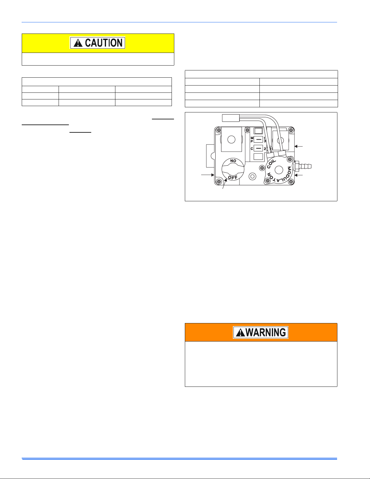
292278-UIM-A-0108
Be sure to relight any gas appliances that were turned off at the
start of this input check.
TABLE 13:
Inlet Gas Pressure Range
INLET GAS PRESSURE RANGE
Natural Gas Propane (LP)
Minimum 4.5” W.C. (1.12 kPa) 8.0” W.C. (1.99 kPa)
Maximum 10.5” W.C. (2.61 kPa) 13.0” (3.24 kPa) W.C.
IMPORTANT: The inlet gas pressure operating range table specifies
what the minimum and maximum gas line pressures must be for the furnace to operate safely.
The gas line pressure MUST BE
• 7” W.C. (1.74 kPA) for Natural Gas
• 11” W.C. (2.74 kPA) for Propane (LP) Gas
in order to obtain the BTU input specified on the rating plate and/or the
nominal manifold pressure specified in these instructions and on the
rating plate.
ADJUSTMENT OF MANIFOLD GAS PRESSURE
Follow the appropriate section in the instructions below. Refer to Figure
23 for a drawing of the locations of the pressure ports on the gas valve.
T urn gas off at the ball valve or gas cock on gas supply line
before the gas valve.
1. The manifold pressure must be taken at the port marked OUT
PRESS TAP.
2. The inlet gas line pressure must be taken at the port marked IN
PRESS TAP.
3. Using a 3/16” allen wrench, remove the plugs from the inlet and
outlet pressure ports. Connect a 1/8” UPT barbed hose fitting to
each pressure port.
Read the inlet gas pressure using the method below.
A. Disconnect the pressure reference hose from the burner box.
Using a tee fitting and a short piece of hose, connect the negative side of the manometer to the burner box as described
below.
B. Remove one end the 5/16” (7.94 mm) ID flexible tubing over
the pressure port on the burner box.
C. Insert the end of the 5/16” (7.94 mm) tubing, that has the 1/8”
(3.175 mm) adapter at the end of the tube, in to the 1/8”
(3.175 mm) tee.
D. Connect the 1/8” (3.175 mm) tee to the burner box adapter
and to the negative side of a U-tube manometer or digital
pressure measuring equipment with 2 – 1/8” (3.175 mm)
tubes.
E. Use the 5/16” (7.94 mm x 1/8” (3.175 mm) reducing coupling
and a 4” (101.6 mm) piece of 1/8” (3.175 mm) tubing to connect the positive side of the manometer to the gas valve pressure reference port. Refer to Figure 24 for connection details.
IMPORTANT: The cap for the pressure regulator must be removed
entirely to gain access to the adjustment screw. Loosening or tightening
the cap does not adjust the flow of gas.
1. Refer to Figure 23 for location of pressure regulator adjustment
cap and adjustment screws on main gas valve.
2. Turn gas and electrical supplies on and follow the operating
instructions to place the unit back in operation.
3. Adjust manifold pressure by adjusting gas valve regulator screw
for the appropriate gas per the following:
TABLE 14:
Nominal Manifold Pressure
NOMINAL MANIFOLD PRESSURE
Natural Gas (Max) 3.5" w.c. (0.87 kPa)
Natural Gas (Min) 0.6" w.c. (0.15 kPa)
Propane (LP) Gas (Max) 10.0" w.c. (2.49 kPa)
Propane (LP) Gas (Min) 1.6" w.c. (0.40 kPa)
MAIN
REGULATOR
ADJUSTMENT
INLET
PRESSURE
TAP
ON/OFF
KNOB
OUTLET
PRESSURE
TAP
FIGURE 23: Gas Valve
IMPORTANT: If gas valve regulator is turned in (clockwise), manifold
pressure is increased. If screw is turned out (counterclockwise), manifold pressure will decrease.
4. After the manifold pressure has been adjusted, re-calculate the
furnace input to make sure you have not exceeded the specified
input on the rating plate. Refer to “CALCULATING THE FURNACE
INPUT (NATURAL GAS)”.
5. Once the correct BTU (kW) input has been established, turn the
gas valve to OFF and turn the electrical supply switch to OFF; then
remove the flexible tubing and fittings from the gas valve pressure
tap and the pressure reference hose from the burner box and
replace the pressure tap plugs. Replace the burner box front cover
(if it was removed) and place the pressure reference hose back on
the gas valve.
6. Turn the electrical and gas supplies back on, and with the burners
in operation, check for gas leakage around the gas valve pressure
port for leakage using an approved gas detector, a non-corrosive
leak detection fluid, or other leak detection methods.
The manifold pressure must be checked with the screw-off cap for
the gas valve pressure regulator in place. If not, the manifold pressure setting could result in an over-fire condition. A high manifold
pressure will cause an over-fire condition, which could cause premature heat exchanger failure. If the manifold pressure is too low,
sooting and eventual clogging of the heat exchanger could occur.
Be sure that gas valve regulator cap is in place and burner box to
gas valve pressure reference hose is connected.
24 Unitary Products Group
Page 25
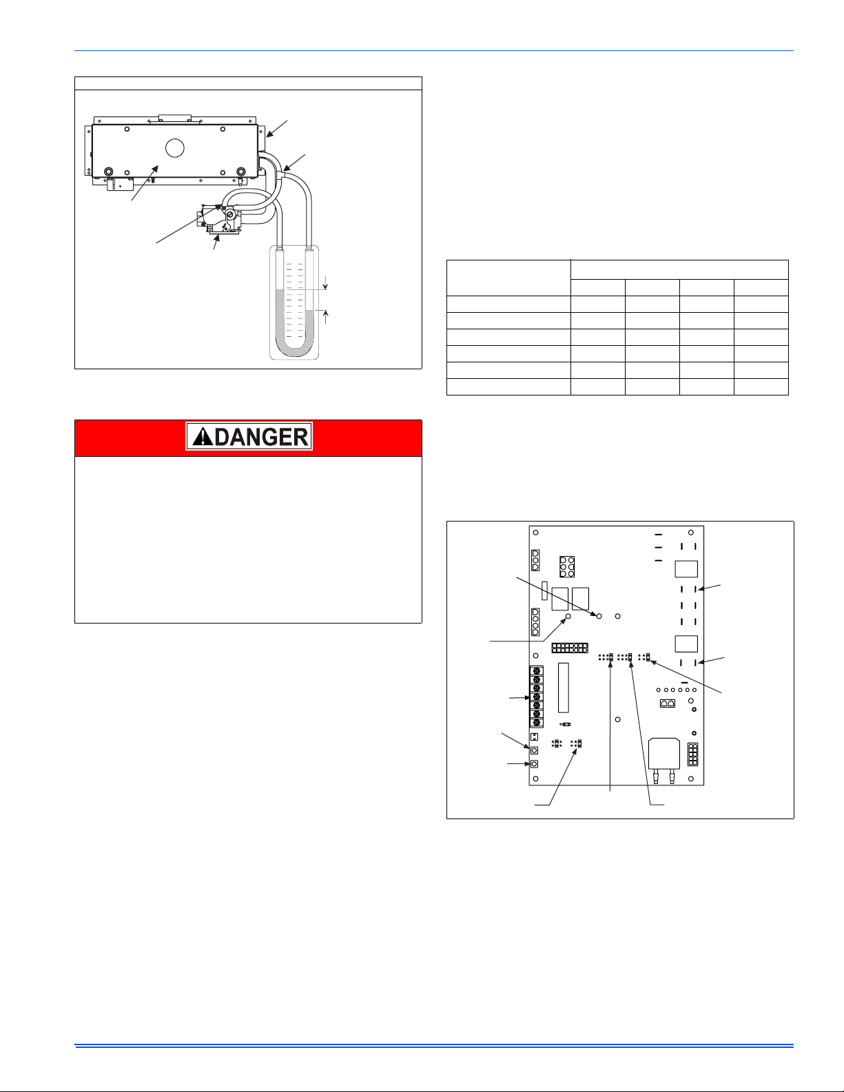
292278-UIM-A-0108
WITH BURNER BOX COVER IN PLACE
BURNER BOX
PRESSURE
REFERENCE
HOSE
TEE
FITTING
BURNER BOX
WITH COVER
OUTLET
PRESSURE
TAP
GAS VALVE
U-TUBE
MANOMETER
6
5
4
3
2
1
0
1
2
3
4
5
6
3.5 IN
WATER
COLUMN
GAS PRESSURE
SHOWN
FIGURE 24: Reading Gas Pressure
ADJUSTMENT OF TEMPERATURE RISE
The temperature rise, or temperature difference between the return
air and the supply (heated) air from the furnace, must be within the
range shown on the furnace rating plate and within the application
limitations shown in Table 5 “ELECTRICAL AND PERFORMANCE
DATA”.
The supply air temperature cannot exceed the “Maximum Supply
Air Temperature” specified in these instructions and on the furnace rating plate. Under NO circumstances can the furnace be
allowed to operate above the Maximum Supply Air Temperature.
Operating the furnace above the Maximum Supply Air Temperature
will cause premature heat exchanger failure, high levels of Carbon
Monoxide, a fire hazard, personal injury, property damage, and/or
death.
The air temperature rise, or difference between the return air temperature and the heated supply air temperature from the furnace, must be
within the air temperature rise range shown on the furnace rating plate
and in Table 5.
After about twenty minutes of operation, determine the furnace temperture rise. Take temperature readings of both the return air and the
heated air in the ducts about six feet away from the furnace, where they
will not be affected by radiant heat. Increase or decrease the temperature rise by changing the ATR jumper on the furnace control board. The
jumper is factory-set to deliver an air temperature rise near the midpoint
of the nameplate temperature rise range. If more air is desired (lower
temperature rise), move the jumper to the -10 position. If less air is
desired (higher temperature rise), move the jumper to the +10 position.
ADJUSTMENT OF FAN CONTROL SETTINGS
Cooling - The airflow delivered by the furnace during cooling operation
can be adjusted to match the cooling capacity of the A/C condensing
unit. This is done by moving the COOL and ADJ jumper on the control
board to give the desired airflow.
The COOL jumper has four positions, which will deliver sufficient airflow
in cooling mode for the cooling capacities shown in the Table 15. The
CFM delivery on each jumper position is shown in Table 16.
the ADJ jumper has three positions which can be used to make further
adjustments to the cooling blower airflow. See Table 16 for further information.
TABLE 15:
Continuous Fan Operation - The airflow delivered by the furnace dur-
ing continuous fan operation can be adjusted as desired. This is done
my moving the RECIRC jumper on the control board to give the desired
airflow.
The jumper has three positions. The "A" position delivers maximum airflow, 100% of the blower capacity. Position "B" delivers approximately
70% of the blower capacity. And Position "C" delivers minimum airflow,
approximately 40% of the blower capacity.
CFM
INDICATOR
DIAGNOSTIC
LIGHT
LOW VOLTAGE
TERMINALS
ERROR
BUTTON
CONTINUOUS FAN
SPEED JUMPER
FIGURE 25: Furnace Control Board
Cooling Airflow - A/C Capacity in Tons
Models
Cool Jumper Position
DCBA
60/1200 1-1/2 2 2-1/2 3
80/1200 1-1/2 2 2-1/2 3
80/1600 2-1/2 3 3-1/2 4
100/1600 2-1/2 3 3-1/2 4
100/2000 3 3-1/2 4 5
120/2000 3 3-1/2 4 5
CFM
DELAY
COOL
ADJUST
HUMIDISTAT
CONNECTED
NO
YES
AIR
RECIRC
TEST
BUTTON
ERROR
TEST
DELAY
JUMPER
COOLING
SPEED JUMPER
HUMIDIFIER
TERMINALS
EAC
TERMINALS
ADJUST
JUMPER
Unitary Products Group 25
Page 26

292278-UIM-A-0108
Delay Taps Selection
The set of jumper pins on the control board labeled "DELAY" are used
to set the delay profiles for the furnace. These can be chosen so as to
maximize the comfort and sound levels for various regions of the country.
Tap A is the default profile. It provides a 30-second ramp-up from zero
airflow to full capacity and a 30-second ramp-down from full capacity
back to zero airflow. Whenever there is a change in airflow mode, such
as from low heat to high heat, the motor will take 30 seconds to ramp
from one speed to the other.
Tap B is the humid profile. This profile is best-suited for installations
where the humidity is frequently very high during cooling season, such
as in the southern part of the country. On a call for cooling, the blower
will ramp up to 50% of full capacity and will stay there for two minutes,
then will ramp up to 82% of full capacity and will stay there for five minutes, and then will ramp up to full capacity, where it will stay until the
wall thermostat is satisfied. In every case, it will take the motor 30 seconds to ramp from one speed to another.
Tap C is the dry profile. This profile is best suited to parts of the country
where excessive humidity is not generally a problem, where the summer months are usually dry. On a call for cooling the motor will ramp up
to full capacity and will stay there until the thermostat is satisfied. At the
end of the cooling cycle, the blower will ramp down to 50% of full capacity where it will stay for 60 seconds. Then it will ramp down to zero. In
every case, it will take the motor 30 seconds to ramp from one speed to
another.
Tap D is the normal profile, best suited for most of the country, where
neither excessive humidity nor extremely dry conditions are the norm.
On a call for cooling, the motor will ramp up to 63% of full capacity and
will stay there for 90 seconds, then will ramp up to full capacity. At the
end of the cooling cycle, the motor will ramp down to 63% of full capacity and will stay there for 30 seconds, then will ramp down to zero. In
every case, it will take the motor 30 seconds to ramp from one speed to
another.
Humidistat
When a humidistat is installed in the system, the “Humidistat connected?” jumper on the control board should be moved to the “YES”
position. The cooling airflow will then be reduced by 15% whenever the
humidistat indicates high humidity.
SECTION XI: NORMAL OPERATION AND
DIAGNOSTICS
NORMAL OPERATION SEQUENCE
The furnace control calculates the optimum firing rate each time the
wall thermostat R and W contacts close or open (at the beginning and
at the end of each call for heat) based on information from the thermostat and past demand. UNLIKE CONVENTIONAL SYSTEMS, THE
WALL THERMOSTAT DOES NOT SIMPLY TURN THE FURNACE ON
AND OFF. THE FURNACE CONTROL CALCULATES THE DEMAND
AND MAY CONTINUE TO FIRE THE FURNACE DURING PORTIONS
OF THE THERMOSTAT "OFF" CYCLE.
When the wall thermostat R and W contacts close, indicating a call for
heat, the following sequence occurs:
1. The inducer is energized and ramps up its speed until airflow is
proven by the pressure switch and by the pressure sensor on the
control board.
2. The hot surface ignitor is energized.
3. After a 17-20 second igniter heatup, the gas valve opens and the
burners light.
4. When the control senses that flame is present, the circulating
blower starts at low speed.
5. The furnace fires at 70% of full rate for 30-45 seconds, then drops
to the minimum (35%) firing rate.
6. The firing rate is automatically adjusted to meet demand, increasing gradually to maximum (100%) firing rate if the thermostat is not
satisfied within a defined time.
7. When the thermostat R and W contacts open (thermostat is satisfied) the furnace control recalculates the demand and a new firing
rate.
a. If demand exceeds the minimum firing rate, the burners will
continue to fire at a recalculated reduced firing rate, decreasing if the thermostat remains off for a defined time.
b. If demand does not exceed the minimum firing rate, the burn-
ers will shut off immediately.
8. After the burners shut off, the circulating blower will continue to run
until the temperature sensor detects that the supply air temperature has dropped to the desired level, which should take from 30 to
90 seconds.
FURNACE CONTROL DIAGNOSTICS
This furnace has built-in self-diagnostic capability. If a system problem
occurs, a flashing LED shows a fault code. The LED can flash red,
green or amber to indicate various conditions. The LED is located on
the furnace control board and can be seen through the clear view port
in the lower door of the furnace. To indicate an error condition, the LED
will turn on for 1/4 second and off for 1/4 second. The pattern will be
repeated the number of times equal to the flash code. For instance, a
"six flash code" will be indicated by the LED turning on and off six times.
There will be a two second off period between each set of flashes. The
flash codes and an indication of their likely causes are listed below:
STEADY OFF - No 24V power to board. Check the 24 volt control circuit fuse on the board. Check the circuit breaker or fuse on the 115 volt
supply power to the furnace. Check that the 24 volt transformer.
One Green Flash - Normal Operation with no call for heat.
Two Green Flashes - Indicator for "No error codes in memory". See
Diagnostic Fault Code Storage and Retrieval section below.
Three Green Flashes - Indicator for "Error codes cleared from mem-
ory". See Diagnostic Fault Code Storage and Retrieval section below.
Rapid Green Flash - Control is in "Factory Speedup" mode. This mode
is used only during factory run-testing of the furnace. To stop this mode,
cycle power to the furnace off and then back on.
One Amber Flash - Normal operation with call for cooling.
Two Amber Flashes - Normal operation with call for heat.
Three Amber Flashes - Normal operation, burner is on at end of heat-
ing cycle after wall thermostat has been satisfied.
Four Amber Flashes - Heating capacity is reduced due to restriction in
the circulating air system. Check for dirty filter or closed registers.
Five Amber Flashes - Heating capacity is reduced due to restriction in
the combustion air or vent system. Check for blocked vent/air pipe or
clogged condensate drain. Above 4,000 feet altitude, this may also indicate automatic, normal derating for altitude. See page 7 for additional
high altitude information.
Rapid Amber Flash - Low flame sense current. Check for dirty or mislocated flame sensor rod.
One Red Flash - Flame is present with no power being supplied to gas
valve. This can be caused by a gas valve that is slow to close or that
leaks gas through to the burners.
Two Red Flashes - Stuck closed pressure switch. The control confirms
that the pressure switch contacts are open at the beginning of each
cycle. This could be caused by a faulty pressure switch or by mis-wiring
of the pressure switch.
Three Red Flashes - Stuck open pressure switch. This indicates that
the pressure switch is open when it should be closed. This could be
caused by a faulty combustion air blower, blocked vent pipe, blocked air
intake pipe, blocked condensate drain, faulty pressure switch hose or a
faulty pressure switch.
26 Unitary Products Group
Page 27

292278-UIM-A-0108
Four Red Flashes - High limit switch open or 24 volt fuse is open. This
may be caused by a dirty air filter, improperly sized duct system, faulty
blower motor, restricted circulating airflow or an open fuse on the control board.
Five Red Flashes - Rollout switch or auxiliary limit switch open. Check
the rollout switch on the side of the burner box. It is a manual reset
switch. To reset, push the small button in the center of the switch. If it
cannot be reset or if the switch trips again, contact a qualified serviceman. Check the limit switch mounted in the combustion air blower housing.
Six Red Flashes - Current failure on modulating gas valve.
Seven Red Flashes - Lockout due to no ignition. The control will try
three times for ignition. If flame cannot be established in three tries, the
control will lockout for one hour and then will try again to light. Check
gas supply, ignitor, gas valve, flame sensor.
Eight Red Flashes - Lockout due to too many flame recycles. This
flash code occurs if flame is lost five times during a single heating cycle.
This could be caused by a faulty gas valve, low gas pressure, or dirty
flame sensor. The control will lock out for one hour and then will try
again.
Nine Red Flashes - Reversed line polarity or improper grounding.
Check polarity of the incoming power to the furnace. Check the grounding of the furnace, including the transformer ground and the L1 and
neutral connections.
Ten Red Flashes - Gas valve circuit shorted. Check gas valve wiring. If
correct, replace gas valve.
Eleven Red Flashes - Main blower failure - This flash code occurs
when the main limit opens and fails to reclose within five minutes, indicating that the blower motor or blower wheel has failed.
Twelve Red Flashes - ID plug is not present or not connected properly,
check for loose plug or loose wires in plug.
Steady On Red - Control fault has been detected or there is 24 volts
present without 115 volts. Check that there is 24 volts and 115 volts
being supplied to the board. If so, then the board should be replaced.
DIAGNOSTIC FAULT CODE STORAGE AND
RETRIEVAL
The control in this furnace is equipped with memory that will store up to
five error codes to allow a service technician to diagnose problems
more easily. This memory will be retained even if power to the furnace
is lost. Only a qualified service technician should use this feature.
The control stores up to five separate error codes. If more than five
error codes have occurred since the last reset, only the five most recent
will be retained. The furnace control board has a button, labeled "LAST
ERROR" that is used to retrieve error codes. This function will only
work if there are no active thermostat signals. So any call for heating,
cooling or continuous fan must be terminated before attempting to
retrieve error codes.
T o retrieve the error codes, push the LAST ERROR button. The LED on
the control will then flash the error codes that are in memory, starting
with the most recent. There will be a two-second pause between each
flash code. After the error codes have all been displayed, the LED will
resume the normal slow green flash after a five second pause. To
repeat the series of error codes, push the button again.
If there are no error codes in memory, the LED will flash two green
flashes. T o clear the memory , push the LAST ERROR button and hold it
for more than five seconds. The LED will flash three green flashes
when the memory has been cleared, then will resume the normal slow
green flash after a five-second pause.
Unitary Products Group 27
Page 28
292278-UIM-A-0108
TABLE 16:
Air Flow Data
HIGH / LOW SPEED COOLING AND HEAT PUMP CFM
60,000 INPUT - 3 Ton 80,000 INPUT - 3 Ton 60,000 INPUT - 3 Ton 80,000 INPUT - 3 Ton
CFM CFM m³/min m³/min
JUMPER SETTINGS
High Low High Low High Low High Low COOL Tap ADJ Tap
1330 900 1310 890 37.7 25.5 37.1 25.2 A B
1130 800 1100 740 32.0 22.7 31.2 21.0 B B
1220 850 1220 830 34.6 24.1 34.6 23.5 A A
1040 730 1000 670 29.4 20.7 28.3 19.0 B A
1120 770 1090 720 31.7 21.8 30.9 20.4 A C
920 650 900 610 26.1 18.4 25.5 17.3 C B
950 660 880 610 26.9 18.7 24.1 17.3 B C
740 540 680 510 21.0 15.3 19.3 14.4 D B
860 610 810 580 24.4 17.3 22.9 16.4 C A
690 540 630 500 19.5 15.3 17.8 14.2 D A
790 570 730 530 22.4 16.1 20.7 15.0 C C
630 530 590 500 17.8 15.0 16.7 14.2 D C
80,000/100,000 INPUT - 4 Ton 100,000 INPUT - 5 Ton 80,000/100,000 INPUT - 4 Ton 100,000 INPUT - 5 Ton
CFM CFM m³/min m³/min
JUMPER SETTINGS
High Low High Low High Low High Low COOL Tap ADJ Tap
1660 1110 2210 1480 47.0 31.4 62.6 41.9 A B
1550 1050 1780 1180 43.9 29.7 50.4 33.4 B B
1610 1070 2040 1350 45.6 30.3 57.8 38.2 A A
1440 960 1620 1050 40.8 27.2 45.9 29.7 B A
1470 990 1840 1250 41.6 28.0 52.1 35.4 A C
1370 920 1560 1010 38.8 26.1 44.2 28.6 C B
1290 850 1470 940 36.5 24.1 41.6 26.6 B C
1130 790 1370 890 32.0 22.4 38.8 25.2 D B
1230 850 1460 930 34.8 24.1 41.3 26.3 C A
1050 720 1250 790 29.7 20.4 35.4 22.4 D A
1110 760 1310 810 31.4 21.5 37.1 22.9 C C
950 660 1090 690 26.9 18.7 30.9 19.5 D C
120,000 INPUT - 5 Ton
CFM
120,000 INPUT - 5 Ton
m³/min
JUMPER SETTINGS
High Low High Low COOL Tap ADJ Tap
2280 1510
1860 1190
2090 1370
1630 1060
1880 1250
1620 1030
1500 960
1410 880
1490 920
1290 790
1360 840
1140 690
All CFM’s are shown at 0.5” w.c. external static pressure.These units have variable speed motors that automatically adjust to provide constant CFM from 0.0” to 0.6” w.c. static
pressure. From 0.6” to 1.0” static pressure, CFM is reduced by 2% per 0.1” increase in static. Operation on duct systems with greater than 1.0” w.c. external static pressure is not
recommended.
NOTE: At some settings, LOW COOL airflow may be lower that what is required to operate an airflow switch on certain models of electronic air cleaners. Consult the instructions
for the electronic air cleaner for further details.
64.6 42.8 AB
52.7 33.7 BB
59.2 38.8 AA
46.2 30.0 BA
53.2 35.4 AC
45.9 29.2 CB
42.5 27.2 BC
39.9 24.9 DB
42.2 26.1 CA
36.5 22.4 DA
38.5 23.8 CC
32.3 19.5 DC
NOTES:
1. Airflow expressed in standard cubic feet per minute (CFM) and in cubic meters per minute (m
2. Return air is through side opposite motor (left side) .
3. In order to stay within the velocity rating the filters, airflows above 1800 CFM (50.97 m
4. Motor voltage at 115V.
FILTER PERFORMANCE
The airflow capacity data published in Table 16 represents blower performance WITHOUT filters. To determine the approximate blower performance of the system, apply the filter drop value for the filter being
NOTE: The filter pressure drop values in Table 17 are typical values for
the type of filter listed and should only be used as a guideline. Actual
pressure drop ratings for each filter type vary between filter manufacturers.
3
/min).
3
/min) require either return from two sides or one side plus bottom.
used or select an appropriate value from the Table 17.
28 Unitary Products Group
Page 29
292278-UIM-A-0108
TABLE 17:
Filter Performance - Pressure Drop Inches W.C. and (kPa)
Airflow Range
CFM
3
m
/min in2 cm
Minimum
Opening Size
Filter Type
Disposable Washable Fiber Pleated
2
In W.C. kPA In W.C. kPA In W.C. kPA
0 - 750 0 - 21.4 230 1484 0.01 0.00249 0.01 0.00249 0.15 0.03736
751 - 1000 21.25 - 28.32 330 2129 0.05 0.01245 0.05 0.01245 0.20 0.04982
1001 - 1250 28.33 - 35.40 330 2129 0.10 0.02491 0.10 0.02491 0.20 0.04982
1251 - 1500 35.41 - 42.48 330 2129 0.10 0.02491 0.10 0.02491 0.25 0.06227
1501 - 1750 42.49 - 49.55 380 2452 0.15 0.03736 0.14 0.03487 0.30 0.07473
1751 - 2000 49.56 - 56.63 380 2542 0.19 0.04733 0.18 0.04484 0.30 0.07473
2001 & Above 56.64 - Above 463 2987 0.19 0.04733 0.18 0.04484 0.30 0.07473
APPLYING FILTER PRESSURE DROP TO
DETERMINE SYSTEM AIRFLOW
To determine the approximate airflow of the unit with a filter in place, follow the steps below:
1. Select the filter type.
2. Select the number of return air openings or calculate the return
opening size in square inches to determine the proper filter pressure drop.
3. Determine the External System Static Pressure (ESP) without the
filter.
4. Select a filter pressure drop from the table based upon the number
of return air openings or return air opening size and add to the
ESP from Step 3 to determine the total system static.
5. If total system static matches a ESP value in the airflow table (i.e.
0.20 w.c. (50 Pa), 0.60 w.c. (150 Pa), etc,) the system airflow corresponds to the intersection of the ESP column and Model/Blower
Speed row.
6. If the total system static falls between ESP values in the table (i.e.
0.58 w.c. (144 Pa), 0.75 w.c. (187 Pa), etc.), the static pressure
may be rounded to the nearest value in the table determining the
airflow using Step 5 or calculate the airflow by using the following
example.
Example: For a 120,000 BTUH (38.06 kW) furnace with 2 return openings and operating on high-speed blower, it is found that total system
static is 0.58” w.c. To determine the system airflow, complete the following steps:
Obtain the airflow values at 0.50 w.c. (125 Pa) & 0.60 w.c. (150 Pa)
ESP.
Airflow @ 0.50”: 2285 CFM (64.70 m
Airflow @ 0.60”: 2175 CFM (61.59 m
3
/min)
3
/min)
Subtract the airflow @ 0.50 w.c. (125 Pa) from the airflow @ 0.60 w.c.
(150 Pa) to obtain airflow difference.
3
2175 - 2285 = -110 CFM (3.11 m
/min)
Subtract the total system static from 0.50 w.c. (125 Pa) and divide this
difference by the difference in ESP values in the table, 0.60 w.c.
(150 Pa) - 0.50 w.c. (125 Pa), to obtain a percentage.
(0.58 - 0.50) / (0.60 - 0.50) = 0.8
Multiply percentage by airflow difference to obtain airflow reduction.
(0.8) X (-110) = -88
Subtract airflow reduction value to airflow @ 0.50 w.c. (125 Pa) to
obtain actual airflow @ 0.58 inwc (144 Pa) ESP.
2285 - 88 = 2197
TABLE 18:
Field Installed Accessories - Non-Electrical
MODEL NO. DESCRIPTION USED WITH
1NP0680 PROPANE (LP) CONVERSION KIT WITH GAS VALVE ALL MODELS
1SF0101 EXTERNAL SIDE FILTER RACK ALL MODELS
1CT0302 CONCENTRIC INTAKE/VENT 2” 60, 80, 100 INPUT MBH
1CT0303 CONCENTRIC INTAKE/VENT 3” 100, 120 MBH
1HT0901 SIDEWALL VENT TERMINATION KIT 3” ALL MODELS
1HT0902 SIDEWALL VENT TERMINATION KIT 2” ALL MODELS
1BR0317
1BR0321 21” CABINETS
EXTERNAL BOTTOM FILTER RACK
1BR0324 24-1/2” CABINETS
1NK0301 CONDENSATE NEUTRALIZER KIT ALL MODELS
1SF0101 SIDE RETURN FILTER KIT 1” FILTER ALL MODELS
1SR0200 SIDE RETURN FILTER KIT 1-4” FILTER ALL MODELS
1BR0117 BOTTOM RETURN FILTER KIT 1” FILTER 17-1/2” CABINETS
1BR0217 BOTTOM RETURN FILTER KIT 1-4” FILTER 17-1/2” CABINETS
1BR0121 BOTTOM RETURN FILTER KIT 1” FILTER 21” CABINETS
1BR0221 BOTTOM RETURN FILTER KIT 1-4” FILTER 21” CABINETS
1BR0124 BOTTOM RETURN FILTER KIT 1” FILTER 24-1/2” CABINETS
1BR0224 BOTTOM RETURN FILTER KIT 1-4” FILTER 24-1/2” CABINETS
17-1/2” CABINETS
Unitary Products Group 29
Page 30
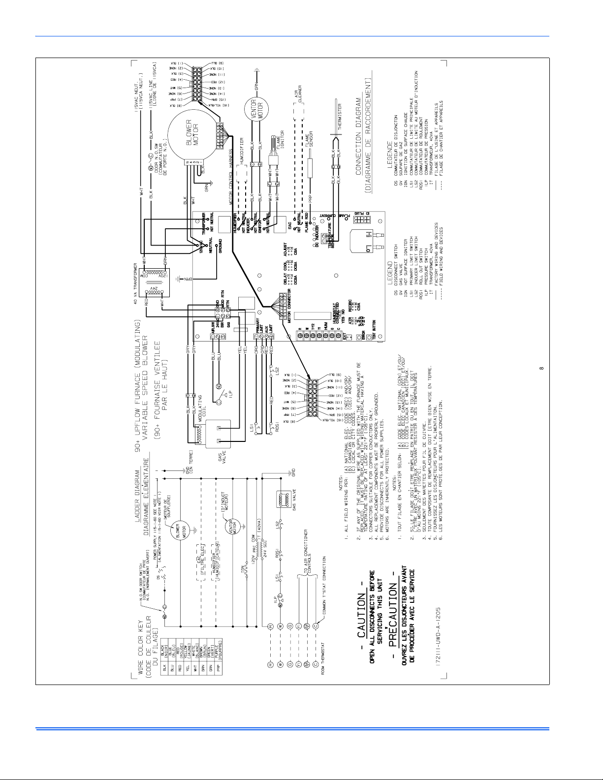
SECTION XII: WIRING DIAGRAM
Jan 04, 2006 03:48PM [a5kps v1.50]
FIGURE 26: Wiring Diagram
Subject to change without notice. Printed in U.S.A. 292278-UIM-A-0108
Copyright © by Unitary Products Group. 2008. All rights reserved. Supersedes: 172078-YIM-C-0606
Unitary 5005 Norman
Product York OK
Group Drive 73069
 Loading...