

Page 1
036-21346-001 Rev. A (202)
TECHNICAL GUIDE
50 Hz SINGLE PACKAGE
ELECTRIC / ELECTRIC AIR-COOLED
AIR CONDITIONER
MODELS:
PAC036 THRU 060
(3 THRU 5 NOMINAL TONS, 3 PHASE)
DESCRIPTION
These units are designed for outdoor installation and offer
electric cooling with an electric heat option for field installation. Only utility and duct connections are required at the
point of installation.
FEATURES
• DURABLE CONSTRUCTION - The outdoor unit is constructed of pre-painted galvanized steel that offers tough
protection against corrosion and resists fading when
exposed to sunlight. Drain holes are incorporated into the
base pan to permit free drainage of moisture.
• RELIABILITY - The compressor is internally protected
against both high pressure and high temperature. Each is
equipped with an internal pressure relief valve and internal
line break overload protection. In addition there is a factory
fitted filter drier.
• QUALITY COILS - The outdoor coil is constructed of copper tube and hardened black coated aluminum fins for
durability and long lasting efficient operation. A factory fitted coil guard provides additional protection.
• LOWER INSTALLED COST - Installation time and costs
are reduced by easy utility connections. The small base
dimensions mean less space is required on the ground or
roof.
• TOP DISCHARGE -The warm condenser air is directed up
and away from the structure and any landscaping.
• LOW OPERATING SOUND LEVEL - In addition to having
a insulated blower compartment, the compressor is
mounted on neoprene isolators to reduce operating
sounds.
• LOW MAINTENANCE - Long-life, permanently lubricated
motor bearings need no annual servicing.
FOR DISTRIBUTION USE ONLY - NOT TO BE USED AT POINT OF RETAIL SALE
Page 2
036-21346-001 Rev. A (202)
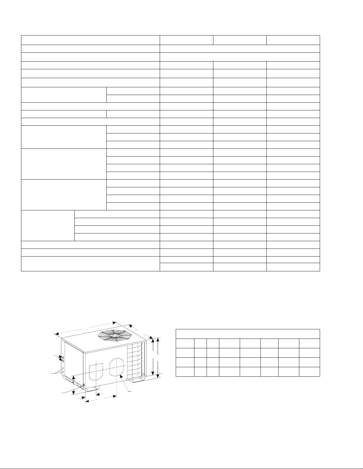
Physical and Electrical Data
MODEL 036H1081A 048H1081A 060H1081A
Unit Supply Voltage 380/415 - 3 - 50
Normal Voltage Range
1
Minimum Circuit Ampacity 12.4 14.8 16.8
Max. Overcurrent Device Amps
Compressor Type
3
Compressor Amps
2
Rated Load 6.1 8.0 9.6
Locked Rotor 39.0 53.0 79.0
15 20 25
Recip Recip Recip
Crankcase Heater No No No
Fan Motor Amps Rated Load 1.8 1.8 1.8
Fan Diameter Inches 18“ 20” 20”
Rated HP 1/3 1/3 1/3
Fan Motor
Nominal RPM 1,100 1,100 1,100
Nominal CFM 2,300 3,000 3,000
Face Area Sq. Ft. 9.25 11.24 11.24
Condenser
Coil Data
Rows Deep 1 2 2
Fin / Inches 18 15 15
Tubing Diameter 3/8 3/8 3/8
Face Area Sq. Ft. 3.61 4.67 4.67
Evaporator
Coil Data
Rows Deep 3 4 4
Fin / Inches 14 12 12
Tubing Diameter 5/16 5/16 5/16
Motor HP / RPM 3/4 / 1,000 3/4 / 1,050 3/4 / 1,100
Blower Data
Max. Static Pressure In. Water .80 .80 .80
Dia. x Width (in.) / Rated CFM 10 x 7/1,200 10 x 7/1,500 10 x 7/1,600
Motor Full Load AMPS 3.0 3.0 3.0
Shipping Weight (lbs.) 270 354 360
Unit Charge (Lbs. - Oz.) 4-4 7-0 7-10
Minimum Wire Size
4
75º C Copper @ 400 Volt
#14 (0-80 ft.) #14 (0-60 ft.) #12 (0-60 ft.)
#12 (81-130 ft.) #12 (61-90 ft.) #10 (61-100 ft.)
342 - 455
1. Rated in accordance with ARI Standard 110, utilization range “A”.
2. Dual element fuses or HACR circuit breaker.
Rated under standard A.R.I. conditions of 80º DB/67º WB indoor, 95º outdoor.
3.
4. Other temperature ratings of wire will have different rated ampacities. Refer to NEC for proper wire sizing recommendations. If using type NM or
NM-B cable, wires must be sized to 60º C ampacities per NEC Article 336, Section 26. NEC and Local Codes superced any wire
recommendations made in these specifications.
All dimensions are in inches. They are subject to change without
notice. Certified dimensions will be provided upon request.
A
B
UNIT DIMENSIONS (INCHES)
UNIT A B C D E F G
HEATER
ACCESSORY
KNOCK-OUTS
CONTROL
WIRING
OPENINGS
3/4” NPT FEMALE
DRAIN OPENING
D
C
G
E
F
12” DIAME TER
RETURN
036 44 30 26 5/8 24 1/8 7 3/4 22 1/2 12 5/8
048 46 32 28 5/8 26 1/8 7 3/4 22 1/8 12 5/8
060 46 32 28 5/8 26 1/8 7 3/4 22 1/8 12 5/8
2 Unitary Products Group
Page 3
036-21346-001 Rev. A (202)
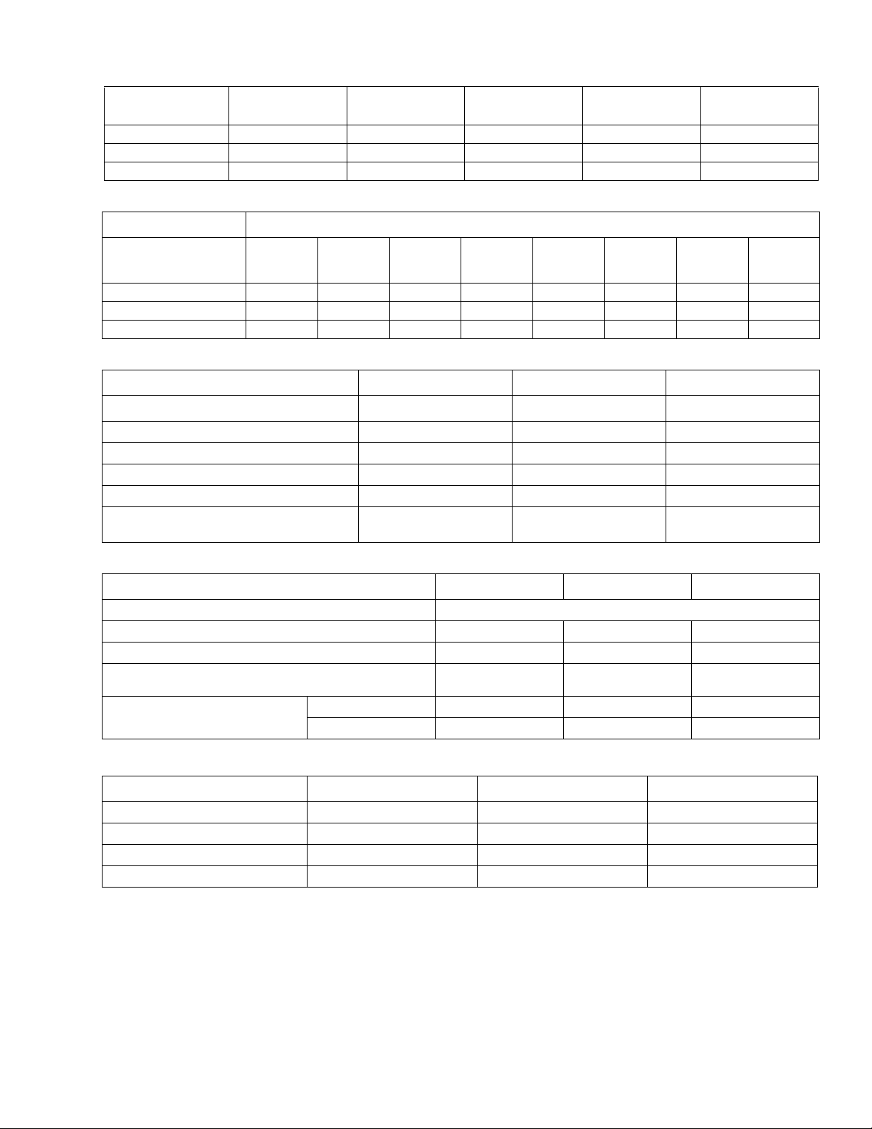
CAPACITY & PERFORMANCE DATA
UNIT MODEL
NUMBER
PAC036H1081A 33,000 3.7 Lbs. 1,200 0.74 8.4
PAC048H1081A 47,000 7.0 Lbs. 1,500 0.68 8.4
PAC060H1081A 55,000 7.6 Lbs. 1,600 0.65 8.4
COOLING
CAPACITY 95°F
UNIT CHARGE
WEIGHT HCFC-22
RATED CFM
SENSIBLE
TOTAL RATIO
SOUND RATING
BLOWER PERFORMANCE DATA
UNIT SPEED STATIC PRESSURE
PAC036H1081A
PAC048H1081A
.1 .2 .3 .4 .5 .6 .7 .8
PAC060H1081A
1837 1781 1720 1672 1607 1534 1443 1352 1243
1489 1468 1441 1412 1378 1336 1279 1204 1120
1238 1228 1216 1207 1180 1138 1088 1024 938
COMPRESSOR DATA
UNIT MODEL PAC036H1081A PAC048H1081A PAC060H1081A
MANUFACTURER
COMPRESSOR MODEL H23A383DBEA H23A543DBEA H26A68QDBEA
RPM (50 Hz) 3,000 3,000 3,000
RATED LOAD AMPS 6.1 8.0 9.6
LOCK ROTOR AMPS 39.0 53.0 79.0
BRANCH CIRCUIT SELECTION
CURRENT (BCSC)
Bristol Bristol Bristol
6.1 8.0 9.6
ELECTRICAL DATA - Packaged A/C (No Electric Heat)
MODEL
Power Supply Volts / Phase / Hertz 380--415 / 3 / 50
Maximum Fuse Size (Amp) 15 20 20
Maximum Circuit Breaker Size (Amp) 15 20 25
Min. Wire Size (AWG) Copper (75_C) Size -- Ft.
Total Input @ Rated Conditions
Running Amps 7.4 10.2 11.3
Running Watts 4,050 5,870 6,650
PAC036H1081A PAC048H1081A PAC060H1081A
#14--0--80
#12--81--130
#14--0--60
#12--61--90
#12--0--60
#10--61--100
CONDENSER COIL DATA
MODEL
Face Area, Sq. Ft. 9.25 11.24 11.24
Tube Diameter Inches 3/8 3/8 3/8
Rows Deep 1 2 2
Fins / Inch 18 15 15
PAC036H1081A PAC048H1081A PAC060H1081A
Unitary Products Group 3
Page 4

036-21346-001 Rev. A (202)
CONDENSER FAN DATA
MODEL PAC036H1081A PAC048H1081A PAC060H1081A
RPM 1,100 1,100 1,100
HP 1/3 1/3 1/3
Nameplate FLA 1.8 1.8 1.8
Dia. / No. Blades 18 / 3 20 / 4 20 / 4
CFM @ 0 S.P. 2,300 3,000 3,000
EVAPORATOR COIL DATA
MODEL PAC036H1081A PAC048H1081A PAC060H1081A
Face Area (Sq. Ft.) 3.61 4.67 4.67
Tube Dia. Ins. 5/16 5/16 3/8
Rows Deep 3 4 4
Fins / Inch 14 12 12
Orifice .071 .079 .081
EVAPORATOR BLOWER DATA
MODEL PAC036H1081A PAC048H1081A PAC060H1081A
Motor HP -- RPM 3/4 -- 1,000 3/4 -- 1,050 3/4 -- 1,100
Static P ressu re
(Inches Water)
Blower Wheel
Dia. x Width
Rated CFM
Nameplate FLA 3.0 3.0 3.0
.5 .5 .5
10 x 7
1,200
10 x 7
1,500
10 x 7
1,600
ELECTRICAL DATA - for Heat Packages Only
HEATER NUMBER 7642-8051 (5.0 KW) 7642-8101 (10.0 KW) 7642-8151 (15.0 KW)
Heater Branch Circuit Electrical Service 2 Leads + 1 Ground 2 Leads + 1 Ground 2 Leads + 1 Ground
415 VAC
Output Capacity
380 VAC
Circuit Number 1 1 1
Nominal Circuit Load - Amps 12.1 24.1 36.2
Heater Circuit Maximum Fuse Size 20 35 45
Minimum Circuit Ampacity 15.9 27.9 40.0
Maximum wire Size
(60° C) CU
CAPACITY 17,000 34,100 51,1000
KW 5.0 10.0 15.0
CAPACITY 15,600 31,200 46,800
KW 4.6 9.2 13.7
0 - 50 Ft. 12 10 8
51 - 100 Ft. 10 8 6
FIELD INSTALLED ACCESSORIES
Refer to price manual for specific model numbers:
Start Assist Kit, Time Delay Kit, Electric Heater Kit and Wall
Thermostat.
Electric Heater Kit - Available in 3 different Kw capacities (5, 10, 15 Kw).
Wall Thermostat - The units are designed to operate
with 24-volt electronic and electric-mechanical thermostats.
4 Unitary Products Group
Page 5

COOLING PERFORMANCE DATA
Unit Model Number PAC036H1081A
AMBIENT TEMPERATURE ENTERING CONDENSING COIL
INDOOR AIR
Indoor
CFM
1000
1345
1400
Unit Model Number PAC048H1081A
INDOOR AIR
Indoor
CFM
1300
1500
1700
Indoor
DB/WB
85/71 37.6 24.5 3.91 35.2 22.4 4.14 32.3 21.1 4.34 29.3 19.7 4.53 26.4 18.4 4.73
80/67 35.3 23.6 3.87 33.1 23.2 4.10 29.0 20.8 4.25 24.9 18.5 4.41 20.8 16.2 4.57
75/63 32.4 22.4 3.80 30.3 21.2 4.03 26.3 19.1 4.14 22.2 17.0 4.25 18.1 14.9 4.36
85/71 38.3 25.9 4.02 35.9 25.1 4.25 33.1 23.4 4.46 30.3 21.6 4.66 25.0 20.1 4.86
80/67 36.2 25.0 3.89 32.6 24.1 4.05 30.1 22.2 4.29 25.8 21.7 4.50 19.8 19.0 4.50
75/63 33.4 23.8 3.82 29.6 23.1 3.98 27.1 20.4 4.17 22.1 20.1 4.36 16.9 16.0 4.42
85/71 39.3 27.4 4.12 37.0 26.4 4.35 34.2 25.0 4.57 31.3 23.5 4.79 28.5 22.1 5.01
80/67 37.2 26.1 4.05 35.0 24.5 4.28 31.3 23.4 4.46 27.5 22.2 4.64 23.7 21.0 4.82
75/63 34.5 25.1 3.98 32.5 22.8 4.20 27.9 21.7 4.34 23.3 20.7 4.47 18.7 19.7 4.60
Indoor
DB/WB
85/71 51.6 31.8 5.44 48.7 30.5 5.79 45.9 29.1 6.13 43.0 27.8 6.47 40.2 26.5 6.81
80/67 48.3 30.9 5.38 45.1 29.3 5.69 41.9 27.6 6.00 38.7 26.0 6.31 35.5 24.4 6.62
75/63 44.7 30.1 5.26 40.9 28.1 5.54 37.0 26.1 5.81 33.2 24.1 6.08 29.4 22.1 6.35
85/71 52.6 33.3 5.56 49.9 32.0 5.92 47.2 30.8 6.27 44.5 29.5 6.63 41.7 28.2 6.99
80/67 49.1 32.5 5.50 47.1 31.4 5.82 43.0 29.6 6.14 36.6 28.2 6.47 31.1 27.1 6.79
75/63 45.6 31.7 5.38 42.3 30.8 5.66 38.1 27.9 5.94 32.4 25.8 6.22 26.0 24.6 6.50
85/71 53.6 34.8 5.68 51.1 33.6 6.05 48.5 32.4 6.42 45.9 31.2 6.79 43.3 30.0 7.16
80/67 49.9 34.1 5.62 47.0 32.9 5.95 44.0 31.6 6.29 41.1 30.3 6.62 38.2 29.0 6.96
75/63 46.4 33.3 5.51 42.8 31.5 5.79 39.1 29.7 6.08 35.4 27.9 6.36 31.7 26.1 6.65
85º 95º 105º 115º 125º
CAPACITY
MBTUH
T.C. S.C. KW T.C. S.C. KW T.C. S.C. KW T.C. S.C. KW T.C. S.C. KW
85º 95º 105º 115º 125º
CAPACITY
MBTUH
T.C. S.C. KW T.C. S.C. KW T.C. S.C. KW T.C. S.C. KW T.C. S.C. KW
CAPACITY
MBTUH
AMBIENT TEMPERATURE ENTERING CONDENSING COIL
CAPACITY
MBTUH
CAPACITY
MBTUH
CAPACITY
MBTUH
CAPACITY
MBTUH
CAPACITY
MBTUH
036-21346-001 Rev. A (202)
CAPACITY
MBTUH
CAPACITY
MBTUH
Unit Model Number PAC060H1081A
AMBIENT TEMPERATURE ENTERING CONDENSING COIL
INDOOR AIR
Indoor
CFM
1500
1560
1700
NOTE: ALL CAPACITIES ARE NET WITH INDOOR FAN HEAT ALREADY DEDUCTED AT 1250 BTUH/1000 CFM.
Indoor
DB/WB
85/71 59.6 37.4 6.25 55.8 35.5 6.62 51.9 33.7 6.98 48.0 31.8 7.35 44.1 30.0 7.72
80/67 55.5 36.5 6.13 51.2 34.3 6.49 46.9 32.2 6.84 42.6 30.0 7.19 38.3 27.9 7.54
75/63 50.4 34.9 6.02 46.2 32.7 6.36 41.9 30.4 6.69 37.6 28.1 7.03 33.3 25.8 7.37
85/71 60.3 38.6 6.32 56.5 36.9 6.70 52.6 35.1 7.07 48.8 33.3 7.44 44.9 31.5 7.81
80/67 56.0 37.8 6.21 55.9 37.0 6.56 47.4 33.5 6.91 47.2 33.1 7.27 40.6 31.1 7.62
75/63 53.3 36.3 6.10 52.7 35.9 6.44 42.6 31.6 6.78 42.0 31.4 7.12 33.5 25.9 7.46
85/71 61.0 39.9 6.40 57.2 38.2 6.78 53.3 36.5 7.15 49.5 34.8 7.53 45.7 33.1 7.91
80/67 56.4 39.1 6.28 52.2 37.0 6.64 47.9 34.8 6.99 43.6 32.6 7.34 39.3 30.4 7.69
75/63 52.2 37.8 6.18 47.7 35.3 6.53 43.3 32.9 6.87 38.8 30.4 7.21 34.4 28.0 7.55
KW RATING IS FOR OUTDOOR UNIT ONLY.
85º 95º 105º 115º 125º
CAPACITY
MBTUH
T.C. S.C. KW T.C. S.C. KW T.C. S.C. KW T.C. S.C. KW T.C. S.C. KW
CAPACITY
MBTUH
CAPACITY
MBTUH
CAPACITY
MBTUH
CAPACITY
MBTUH
Unitary Products Group 5
Page 6

036-21346-001 Rev. A (202)
NOTES
6 Unitary Products Group
Page 7

036-21346-001 Rev. A (202)
Unitary Products Group 7
Page 8

Subject to change without notice. Printed in U.S.A. 036-21346-001 Rev. A (202)
K
Copyright © by York International Corp. 2002. All rights reserved. Supersedes: T-734 Rev. 3, 530.10-TG2YI (899)
Unitary 5005 Norman
Products York O
Group Drive 73069
 Loading...