

York UQ Latitude R410A, NM, UQ, NM Latitude R410A Technical Guide
®
546039-YTG-C-0211
ISO 9001
Certified Quality
Management System
TECHNICAL GUIDE
R-410A, 13 SEER
LATITUDE™ SERIES
60 Hertz
Description
These York® Latitude™ packaged cooling/heating air
conditioners are designed for outdoor installation. Only utility
and duct connections are required at the point of installation.
Field-installed electric heater accessories are available to
provide electric heat, if required. (Single phase only)
Tested in accordance with:
FOR DISTRIBUTION USE ONLY - NOT TO BE USED AT POINT OF RETAIL SALE
546039-YTG-C-0211
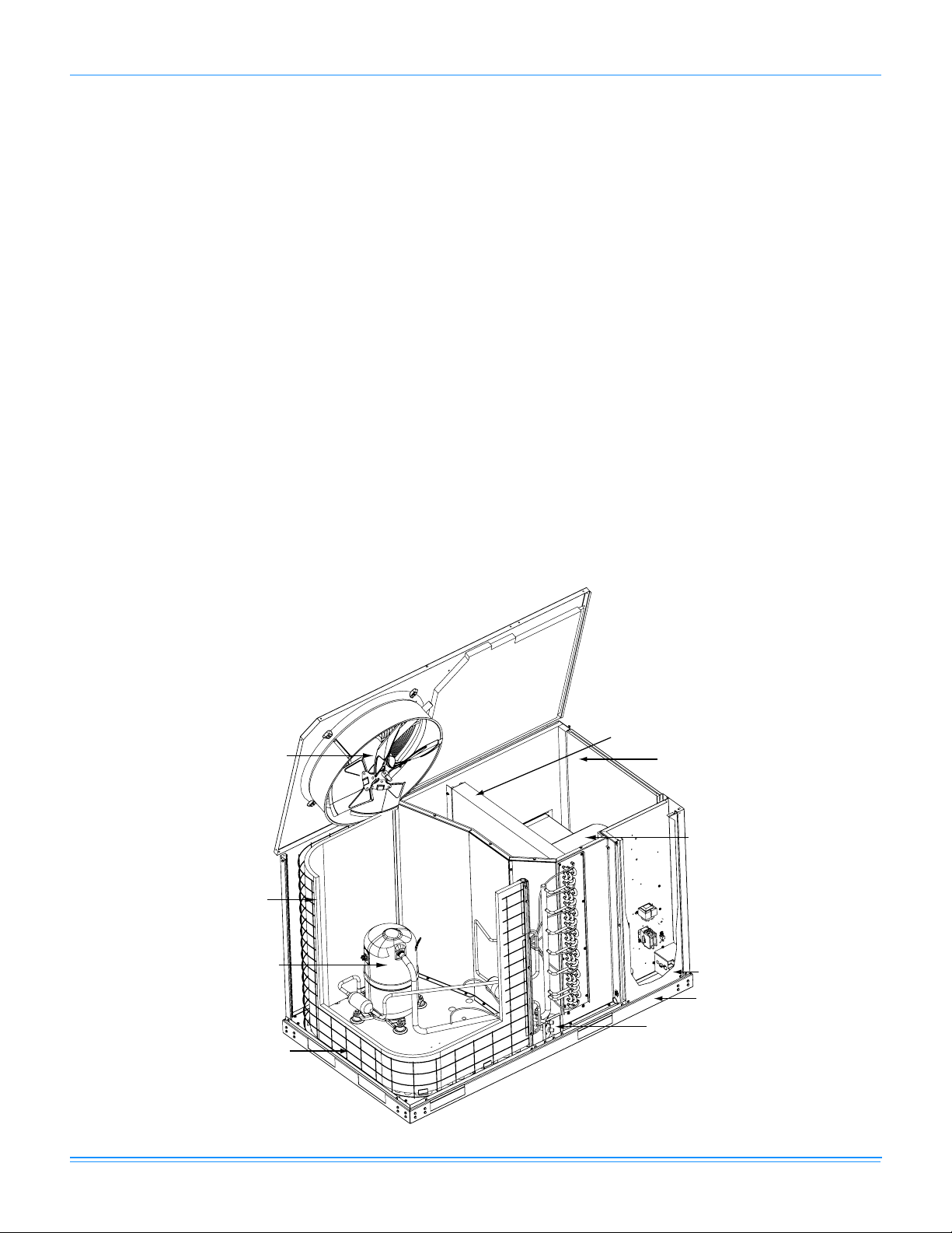
Direct Drive
Condenser Fan Motor
High Efficiency Enhanced
Copper Tube/Aluminum Fin
or
Micro-Channel Aluminum
Tube/Aluminum Fin
Outdoor Coil
High Efficiency
Compressor Rigidly
Mounted
Decorative Protective
Coil Guard
High Efficiency Enhanced
Copper Tube/Aluminum Fin
Outdoor Coil
Blower Service
Access Panel
X13 or PSC
Direct Drive
Blower Motor
Refrigerant
Connections
Control Box Service
Access Panel
Heavy Gauge
Base Rails
Table of Contents
Description . . . . . . . . . . . . . . . . . . . . . . . . . . . . . . . . . . . . . . . . . . . . . . . . . . . . . . . . . . . . . . . . . . . . . . . . . . . . . . . . . . . . . . . . . . . . 1
Table of Contents . . . . . . . . . . . . . . . . . . . . . . . . . . . . . . . . . . . . . . . . . . . . . . . . . . . . . . . . . . . . . . . . . . . . . . . . . . . . . . . . . . . . . . . 2
Component Location . . . . . . . . . . . . . . . . . . . . . . . . . . . . . . . . . . . . . . . . . . . . . . . . . . . . . . . . . . . . . . . . . . . . . . . . . . . . . . . . . . . . 2
Nomenclature . . . . . . . . . . . . . . . . . . . . . . . . . . . . . . . . . . . . . . . . . . . . . . . . . . . . . . . . . . . . . . . . . . . . . . . . . . . . . . . . . . . . . . . . . . 3
Features and Benefits . . . . . . . . . . . . . . . . . . . . . . . . . . . . . . . . . . . . . . . . . . . . . . . . . . . . . . . . . . . . . . . . . . . . . . . . . . . . . . . . . . . . 3
Guide Specifications . . . . . . . . . . . . . . . . . . . . . . . . . . . . . . . . . . . . . . . . . . . . . . . . . . . . . . . . . . . . . . . . . . . . . . . . . . . . . . . . . . . . . 4
Physical Data . . . . . . . . . . . . . . . . . . . . . . . . . . . . . . . . . . . . . . . . . . . . . . . . . . . . . . . . . . . . . . . . . . . . . . . . . . . . . . . . . . . . . . . . . . . 6
Capacity Performance . . . . . . . . . . . . . . . . . . . . . . . . . . . . . . . . . . . . . . . . . . . . . . . . . . . . . . . . . . . . . . . . . . . . . . . . . . . . . . . . . . . 9
Airflow Performance . . . . . . . . . . . . . . . . . . . . . . . . . . . . . . . . . . . . . . . . . . . . . . . . . . . . . . . . . . . . . . . . . . . . . . . . . . . . . . . . . . . . 35
Sound Performance . . . . . . . . . . . . . . . . . . . . . . . . . . . . . . . . . . . . . . . . . . . . . . . . . . . . . . . . . . . . . . . . . . . . . . . . . . . . . . . . . . . . 39
Electrical Data . . . . . . . . . . . . . . . . . . . . . . . . . . . . . . . . . . . . . . . . . . . . . . . . . . . . . . . . . . . . . . . . . . . . . . . . . . . . . . . . . . . . . . . . . 39
Weights and Dimensions . . . . . . . . . . . . . . . . . . . . . . . . . . . . . . . . . . . . . . . . . . . . . . . . . . . . . . . . . . . . . . . . . . . . . . . . . . . . . . . . 49
Component Location
Cooling Unit and Heat Pump
2 Unitary Products Group
546039-YTG-C-0211
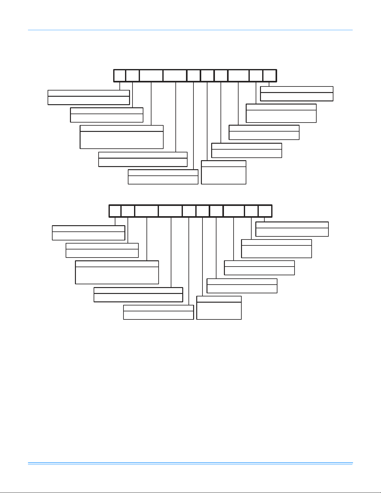
N M
036 C 00
AA
1 A A 1 A
Product Category
N = Single Package Air Conditioner, R-410A
Heat Type & Nominal Heat Capacity
C00 = Cooling Only
Product Identifier
M = 13 SEER A/C
Airflow
A = Standard Drive
Installation Options
A = No Options Installed
Voltage Code
1 = 208/230-1-60
2 = 208/230-3-60
4 = 460-3-60
Product Style
A = Style A
Additional Options
AA = None
Product Generation
1 = First Generation
2 = Second Generation
042 = 3.5 Ton
048 = 4.0 Ton
060 = 5.0 Ton
024 = 2.0 Ton
030 = 2.5 Ton
036 = 3.0 Ton
Nominal Cooling Capacity (MBH)
U Q
036 C 00
AA
1 A A 1 A
Product Category
U = Single Package Heat Pump, R-410A
Heat Type & Nominal Heat Capacity
C00 = Cooling Only
Product Identifier
Q = 13 SEER Heat Pump
Airflow
A = Standard Drive
Installation Options
A = No Options Installed
Voltage Code
1 = 208/230-1-60
2 = 208/230-3-60
4 = 460-3-60
Product Style
A = Style A
Additional Options
AA = None
Product Generation
1 = First Generation
2 = Second Generation
Nominal Cooling Capacity (MBH)
042 = 3.5 Ton
048 = 4.0 Ton
060 = 5.0 Ton
024 = 2.0 Ton
030 = 2.5 Ton
036 = 3.0 Ton
Nomenclature
Cooling Unit
Heat Pump
Features and Benefits
Standard Features
• Operating Efficiency - All cooling units provide a SEER
of 13.0.
All heat pump units provide operating efficiency of 13.0
SEER and 7.7 HSPF. All efficiencies meet legislated
minimum levels.
• Lower Installation Cost - Installation time and costs are
reduced by easy power and control wiring connections.
The small base dimension means less space is required
on the ground or roof, plus, the installer can fit this unit
between the wheel wells of full size pick-up truck. All
models are well under 400 pounds.
All units are completely wired, charged with R-410A and
tested prior to shipment. Unique test stations using a new
state of the art computerized process system are used to
Unitary Products Group 3
insure product quality. Refrigerant charge and component
part numbers are verified via computers at assembly. Vital
run test statistics such as system pressure, motor
currents, air velocity and temperature, unit vibration, and
gas system safeties are monitored and recorded by the
system to insure unit performance.
Equal size, side supply and return duct connections
allows easy hook-up of ducts to match low crawl spaces
without transition pieces.
• Coil Technology - All cooling units utilize Micro-Channel
"all-aluminum" condensers which provide improved heat
transfer capabilities, and reduced charge volumes. All
evaporators utilize a conventional copper tube/aluminum
fin design for proven reliability and performance.
• Utility Connections Made Easy - Electric utility
knockouts are provided through the side of the unit. Utility
connections can be made quickly and with a minimum

546039-YTG-C-0211
amount of field labor. A field supplied and field installed
electrical disconnect switch must be installed.
• Round Duct Flanges - (Factory Supplied - Field
Installed) Equal size, side supply and return duct flanges
allow easy hook-up of ducts.
• Condensate Pan - A non-corrosive, long-lasting, watertight pan is positioned below the evaporator coil to collect
and drain all condensate. Less collection of stagnate
condensate will build-up. The condensate pan conforms
to ASHRAE 62-89 standards (Ventilation for Acceptable
Indoor Air Quality).
• Condensate Drain - The 3/4 inch NPTF connection is
rigidly mounted to assure proper fit and leak tight seal.
• Durable Finish - With a heavy duty cabinet made of
powder-painted, galvanized steel the neutral color blends
into surrounding areas. The powdered paint provides a
better paint to steel bond , which resists corrosion and rus t
creep. The glossy finish insures less fading when exposed
to sunlight and offers a more attractive on site
appearance. This paint finish meets ASTM-B117
standards for 1000 hours salt spray rating, the highest in
the industry.
• Full Perimeter Base Rails - The base rails provide a
solid foundation for the entire unit and protects the unit
during shipment. The rails provide fork lift access from all
sides. On applications where the unit is placed on a pad,
the base will keep the unit off the pad to deter corrosion.
• More Attractive Appearance - A single piece Water
Shed top cover containing a top discharge condenser fan
arrangement requires less square footage on installation
and provides a wider variety of installations. The one
piece design adds greater water integrity.
• Top Discharge - The top discharge condenser fan does
not disrupt neighboring areas or dry-out vegetation
surrounding the unit. The warm air from the top mounted
fan is blown up away from the structure and any
landscaping. This allows compact location on multi-unit
applications.
• Condenser Coil Grille - All models utilize a decorati ve
"Wire Form" coil guard to provide impact protection
against large objects.
• Low Operating Sound Level - The upward air flow
carries the normal operating noise up and away from the
living area. The rigid top panel effectively isolates any
motor sound. Isolator mounted compressor and the
rippled fins of the condenser coil muffle the normal fan
motor and compressor operating sounds.
• Fan System - 2, 2-1/2 and 3 Ton A/C models operate with
a 3-speed PSC (Permanent Split Capacitor) fan motor. 4
and 5 Ton A/C and all Heat Pump models operate with a
constant torque (X Motor) fan motor with 5 speed taps. All
these units easily match all types of applications and
provide greater on site flexibility to match comfort
requirements.
• Protected Compressor - The compressor is internally
protected against high pressure and temperature. This is
accomplished by the simultaneous operation of high
pressure relief valve and a temperature sensor which protect
the compressor if undesirable operating conditions occur.
• Pressure Switches - High pressure and low pressure/
loss of charge switches standard in all units. On Heat
Pump models, when abnormal conditions are sensed
through the pressure switches, the unit will lock-out
preventing further operation until reset or the problem is
corrected.
• Exclusive Coil Design - Grooved copper tubes and
enhanced aluminum fin construction on all indoor coils
and heat pump outdoor coils improve heat transfer for
maximum efficiency and durability or Micro-Channel
aluminum tube, aluminum fin on all cooling outdoor coils
for long lasting durability and efficient operation.
Low Maintenance - Long life, permanently lubricated
•
condenser and evaporator fan motor bearings need no
annual maintenance adding greater reliability to the unit.
• Secured Service Access Ports - Protected, externally
mounted, re-usable service access ports are provided on
both the high and low lines for ease of evacuating and
charging the system. No final field mounting required.
• Easy Service Access - A large, single panel covers the
electrical controls makes servicing easy. The blower
compartment has a large panel which when removed will
allow the blower fan assembly to slide-out for ease of
maintenance and trouble shooting.
• Replacement Parts - The installer requires no special
training to replace any of the components of these units
and does not need to maintain an inventory of unique
parts.
Field Installed Accessories
• Wall Thermostat - The units are designed to operate with
24-volt electronic and electro-mechanical thermostats.
• Electric Heat Kit - Available in 4 different kW capacities
(5, 7, 10 and 15 kW). (Single phase only)
• Start Assist Kits - Available for all models.
• Outdoor Thermostat - Available for all heat pump models.
Guide Specifications
GENERAL
Units shall be factory-assembled, single packaged, Electric
Cooling units, designed for outdoor mounted installation. Units
shall have minimum SEER ratings of 13.0. Heat pump 7.7 HSPF.
The units shall be factory wired, piped, charged with R-410A
refrigerant and factory tested prior to shipment. All unit wiring
shall be color coded.
All units shall be manufactured in a facility certified to ISO 9001
standards, and the cooling performance shall be rated in
accordance with DOE and ARI test procedures. Units shall be
certified to UL 1995/CAN/CSA C22.2 No. 236 standards.
4 Unitary Products Group

546039-YTG-C-0211
UNIT CABINET
1. Unit cabinet shall be constructed of galvanized steel, with
exterior surfaces coated with a non-chalking, powdered
paint finish, certified at 1000 hours salt spray test per
ASTM-B117 standards.
2. The unit top shall be a single piece "Water Shed" design.
3. Unit shall have a rigidly mounted condenser coil guard to
provide protection from objects and personnel after
installation.
4. Indoor blower section shall be insulated with up to 3/4"
thick insulation.
5. Cabinet panels shall be "large" size, easily removable for
servicing and maintenance.
6. Unit shall be built on a formed, "Super-Structure" design
base pan, with embossments at critical points to add
strength, rigidity and aid in minimizing sound.
7. Full perimeter base rails shall be provided to assure
reliable transit of equipment.
8. Condensate pan shall be internally sloped and conform to
ASHARE 62-89 self-draining standards, with 3/4" NPTF
ridged mount connection.
INDOOR (EVAPORATOR) FAN ASSEMBLY
1. Fan shall be direct drive, either 3 speed PSC (Permanent
Split Capacitor) or 5 speed constant torque (X Motor)
design.
2. Fan wheel shall be double-inlet type with forward-curved
blades, dynamically balanced to operate smoothly
throughout the entire range of operation. Airflow design
shall be constant air volume.
3. Bearings shall be sealed and permanently lubricated for
longer life and no maintenance.
4. Fan assembly shall be accessible via removable inlet ring.
OUTDOOR (CONDENSER) FAN ASSEMBLY
1. The outdoor fan shall be of the direct-driven propeller type,
discharge air vertically, have aluminum blades riveted to
corrosion resistant steel spider bracket and shall be
statically balanced for smooth operation.
2. The outdoor fan motor shall be totally enclosed with
permanently lubricated bearings and internally protected
against overload conditions.
REFRIGERANT COMPONENTS
Compressors:
a. Shall be fully hermetic reciprocating, rotary or scroll type,
direct drive, internally protected with internal highpressure relief and over temperature protection. The
hermetic motor shall be suction gas cooled and have a
voltage range of + or - 10% of the unit nameplate
voltage.
b. Shall have internal isolation and sound muffling to
minimize vibration and noise, and be externally isolated
on a dedicated, independent mounting.
Coils:
a. Evaporator coils shall have aluminum plate fins
mechanically bonded to seamless internally enhanced
copper tubes with all joints brazed.
b. Evaporator coil shall be of the direct expansion, blow
through design.
c. Condenser coils shall have aluminum plate fins
mechanically bonded to seamless internally enhanced
copper tubes with all joints brazed or Micro-Channel
aluminum tube, aluminum fins.
d. Condenser coil shall be draw through design.
Refrigerant Circuit and Refrigerant Safety Components shall
include:
a. Independent fixed-orifice or TXV expansion devices.
b. Filter/strainer to eliminate any foreign matter.
c. Accessible service gage connections on both suction
and discharge lines to charge, evacuate, and measure
refrigerant pressure during any necessary servicing or
troubleshooting, without losing charge and without
disrupting condenser or evaporator air flow.
Unit Controls:
a. Controls shall be mounted in a large control box, allowing
easy access for trouble shooting and maintenance
without affecting the normal system operation pressures.
b. Unit shall have large, easily removable panels, covering
electrical controls and compressor, allowing easy access
for any necessary maintenance or servicing.
ELECTRIC HEATING SECTION
1. An electric heating section, with nickel chromium elements,
shall be provided in a range of 5 thru 15 KW, single phase
only.
2. The heating section shall have a primary limit control(s)
and automatic reset, to prevent the heating element
system from operating at an excessive temperature.
3. The heating section assembly shall slide out of the unit for
easy maintenance and service.
UNIT OPERATING CHARACTERISITCS
1. Unit shall be capable of starting and running at 125° F
outdoor temperature, exceeding maximum load criteria of
ARI Standard 210/240.
2. The compressor, with standard controls, shall be capable
of cooling operation down to 45° F outdoor temperature.
ELECTRICAL REQUIREMENTS
All unit power wiring shall enter unit cabinet at a single factory
provided location.
Separate openings shall be provided for the control wiring.
Unitary Products Group 5
546039-YTG-C-0211
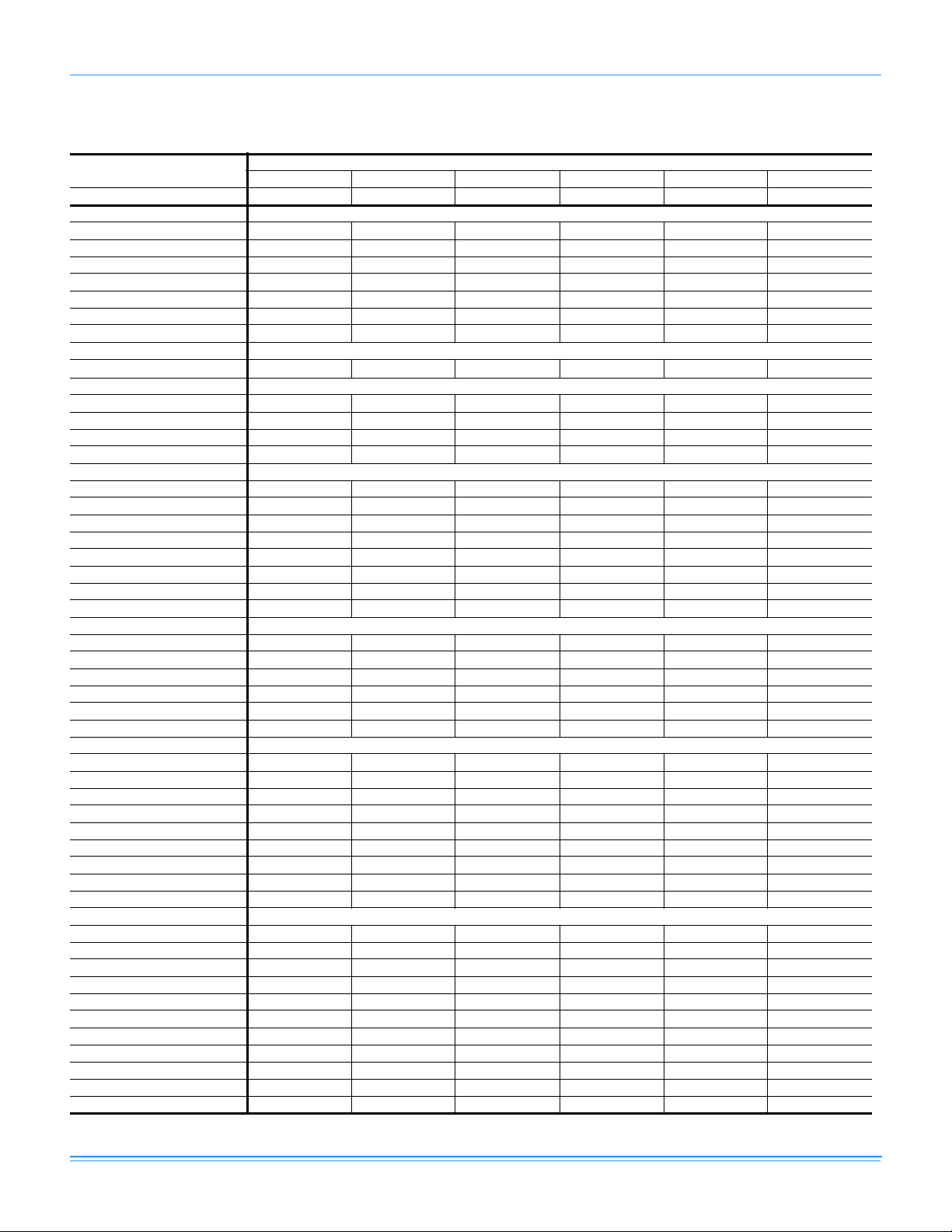
Physical Data
NM024-060 Physical Data
Component
Nominal Tonnage 2.0 2.5 3.0 3.5 4.0 5.0
ARI COOLING PERFORMANCE
Gross Capacity @ ARI A point (Btu) 24300 31500 37000 41400 48100 57500
ARI net capacity (Btu) 23300 30200 35400 40200 46500 55800
EER 10.8 11.4 11 10.8 11.2 10.8
SEER 13 13 13 13 13 13
Nominal CFM 850 1000 1200 1150 1450 1700
System power (KW) 2.15 2.64 3.21 3.72 4.15 5.17
Refrigerant type R-410A R-410A R-410A R-410A R-410A R-410A
Refrigerant charge (lb-oz)
System 1
DIMENSIONS (inches)
Length 47-1/4 47-1/4 47-1/4 47-1/4 57-9/16 57-9/16
Width 32-13/16 32-13/16 32-13/16 32-13/16 32-13/16 32-13/16
Height 30-15/16 30-15/16 30-15/16 30-15/16 34-15/16 34-15/16
OPERATING WT. (lbs.) 276 279 315 315 357 350
COMPRESSORS
Type Recip Recip Recip Recip Recip Scroll
Quantity 111111
CONDENSER COIL DATA
Face area (Sq. Ft.) 11.2 11.2 11.2 11.2 15.1 15.1
Rows 111111
Fins per inch 23 23 23 23 23 23
Tube diameter (in.) .71/18 .71/18 .71/18 .71/18 .71/18 .71/18
Circuitry Type 2-pass Microchannel 2-pass Microchannel 2-pass Microchannel 2-pass Microchannel 2-pass Microchannel 2-pass Microchannel
EVAPORATOR COIL DATA
Face area (Sq. Ft.) 4.67 4.67 4.67 4.67 5.44 5.44
Rows 334434
Fins per inch 13 13 13 13 13 13
Tube diameter 3/8 3/8 3/8 3/8 3/8 3/8
Circuitry Type Intertwined Intertwined Intertwined Intertwined Intertwined Intertwined
Refrigerant control Orifice Orifice Orifice Orifice Orifice Orifice
CONDENSER FAN DATA
Quantity 111111
Fan diameter (Inch) 20 20 20 20 22 22
Type Prop Prop Prop Prop Prop Prop
Drive type Direct Direct Direct Direct Direct Direct
No. speeds 1 1 1 1 1 1
Number of motors 1 1 1 1 1 1
Motor HP each 1/4 1/4 1/4 1/3 1/3 1/3
RPM 850 1100 1100 1100 1100 1100
Nominal total CFM 2500 2800 2800 3000 3200 3200
DIRECT DRIVE EVAP FAN DATA
Quantity 111111
Fan Size (Inch) 10 x 7 10 x 7 10 x 7 10 x 7 11 x 10 11 x 10
Fan type Centrifugal Centrifugal Centrifugal Centrifugal Centrifugal Centrifugal
Drive type Direct Direct Direct Direct Direct Direct
No. speeds 3 3 3 5 5 5
Number of Motors 1 1 1 1 1 1
Motor HP each 1/2 1/2 1/2 1/2 1 1
RPM 1075 1075 1075 1100 1100 1100
Frame size 48 48 48 48 48 48
FILTERS
Quantity - Size ------
NM024 NM030 NM036 NM042 NM048 NM060
4-6 4-6 4-8 4-8 4-12 4-14
Models
6 Unitary Products Group
546039-YTG-C-0211
UQ024-060 Physical Data
Component
Nominal Tonnage 2.0 2.5 3.0 3.5 4.0 5.0
ARI COOLING PERFORMANCE
Gross Capacity @ ARI A point (Btu) 23220 28750 37000 41404 48000 54384
ARI net capacity (Btu) 22600 28000 35200 40200 46500 53000
EER 11.2 11.2 11.2 11.4 11.6 10.8
SEER 13 13 13 13 13 13
Nominal CFM 900 1000 1200 1450 1600 1650
System power (KW) 2.02 2.50 3.16 3.74 4.02 4.84
Refrigerant type R-410A R-410A R-410A R-410A R-410A R-410A
Refrigerant charge (lb-oz)
System 1
ARI HEATING PERFORMANCE
47°F Capacity Rating (MBH) 20000 26500 32000 38300 43000 50000
System Power KW/COP 1720/3.4 2386/3.25 2930/3.2 3280/3.40 3654/3.45 4523/3.25
17°F Capacity Rating (MBH) 11000 14800 18400 21600 24400 29200
System Power KW/COP 1610/2.00 2122/2.04 2598/2.04 3125/2.03 3437/2.08 4057/2.10
HSPF BTU/Watts-hr 7.7 7.7 7.7 7.7 7.7 7.7
DIMENSIONS (inches)
Length 47-1/4 47-1/4 47-1/4 57-9/16 57-9/16 57-9/16
Width 32-13/16 32-13/16 32-13/16 32-13/16 32-13/16 32-13/16
Height 30-15/16 30-15/16 30-15/16 34-15/16 34-15/16 34-15/16
OPERATING WT. (lbs.) 325 340 340 372 382 390
COMPRESSORS
Type Scroll Scroll Scroll Scroll Scroll Scroll
Quantity 111111
CONDENSER COIL DATA
Face area (Sq. Ft.) 11.1 11.28 11.28 16 16 20
Rows 122222
Fins per inch 20 15 20 15 15 20
Tube diameter (in.) 3/8 3/8 3/8 3/8 3/8 3/8
Circuitry Type Intertwined Intertwined Intertwined Intertwined Intertwined Intertwined
Refrigerant Control TXV TXV TXV TXV TXV TXV
EVAPORATOR COIL DATA
Face area (Sq. Ft.) 4.67 4.67 4.67 5.44 5.44 5.44
Rows 333444
Fins per inch 13 13 16 13 13 13
Tube diameter 3/8 3/8 3/8 3/8 3/8 3/8
Circuitry Type Intertwined Intertwined Intertwined Intertwined Intertwined Intertwined
Refrigerant control Orifice Orifice Orifice Orifice Orifice TXV
CONDENSER FAN DATA
Quantity 111111
Fan diameter (Inch) 20 20 20 22 22 22
Fan type Prop Prop Prop Prop Prop Prop
Drive type Direct Direct Direct Direct Direct Direct
No. speeds 1 1 1 1 1 1
Number of motors 1 1 1 1 1 1
Motor HP each 1/4 1/4 1/4 1/3 1/3 1/3
RPM 850 850 1100 1100 1100 1100
Nominal total CFM 2500 2500 2850 3200 3200 3200
DIRECT DRIVE EVAP FAN DATA
Quantity 111111
Fan diameter (Inch) 10 x 7 10 x 7 10 x 7 11 x 10 11 x 10 11 x 10
Fan type Centrifugal Centrifugal Centrifugal Centrifugal Centrifugal Centrifugal
Drive type Direct Direct Direct Direct Direct Direct
No. speeds 5 5 5 5 5 5
Number of motors 1 1 1 1 1 1
Motor HP each 1/2 1/2 1/2 1 1 1
RPM 1100 1100 1100 1100 1100 1100
Frame size 48 48 48 48 48 48
FILTERS
Size / Quantity ------
UQ024 UQ030 UQ036 UQ042 UQ048 UQ060
7-7 9-4 9-10 12-4 12-8 12-8
Models
Unitary Products Group 7
NM and UQ Unit Limitations
546039-YTG-C-0211
Size
(Tons)
024
(2.0)
030
(2.5)
036
(3.0)
042
(3.5)
048
(4.0)
060
(5.0)
Model Unit Voltage
NM
UQ
NM
UQ
NM
UQ
NM
UQ
NM
UQ
NM
UQ
208/230-1-60 187 252 125
208/230-1-60 187 252 125
208/230-1-60 187 252 125
208/230-3-60 187 252 125
208/230-1-60 187 252 125
208/230-1-60 187 252 125
208/230-3-60 187 252 125
460-3-60 432 504 125
208/230-1-60 187 252 125
208/230-3-60 187 252 125
460-3-60 432 504 125
Unit Limitations
Applied Voltage Outdoor DB Temp
Min Max Max (°F)
8 Unitary Products Group
546039-YTG-C-0211
Capacity Performance
NM024-060 Cooling Capacities
NM024 (2.0 Ton)
Air on
Evaporator Coil
500
600
700
800
900
500
600
700
800
900
WB
(°F)
77 35.1 1.8 14.7 12.1 9.8 - - - 31.8 1.9 13.1 10.9 8.7 - - 72 31.6 1.8 17.5 15.2 12.9 10.6 - - 28.1 1.9 16.1 13.9 11.7 9.5 - 67 28.0 1.8 20.4 18.4 16.1 13.8 11.5 - 24.5 1.9 19.2 16.9 14.7 12.5 10.3 62 24.6 1.8 24.6 20.0 17.9 15.6 13.3 11.0 21.3 1.9 21.3 18.5 16.0 13.8 11.6 9.4
77 36.0 1.8 15.9 13.3 10.7 - - - 32.7 2.0 14.6 12.1 9.5 - - 72 32.4 1.8 19.3 16.7 14.1 11.5 - - 29.0 2.0 17.9 15.4 12.8 10.3 - 67 28.7 1.8 22.7 20.1 17.5 14.9 12.3 - 25.2 1.9 21.2 18.7 16.1 13.6 11.0 62 25.2 1.8 25.2 22.1 19.5 16.9 14.3 11.7 22.0 1.9 22.0 20.1 17.6 15.0 12.5 9.9
57 24.0 1.8 24.0 24.0 21.5 18.9 16.3 13.7 21.1 1.9 21.1 21.1 19.0 16.5 13.9 11.4
77 36.9 1.8 17.1 14.5 11.6 - - - 33.7 2.0 16.1 13.2 10.3 - - 72 33.2 1.8 21.1 18.2 15.3 12.4 - - 29.9 2.0 19.7 16.8 14.0 11.1 - 67 29.5 1.8 25.1 21.9 19.0 16.1 13.2 - 26.0 2.0 23.3 20.4 17.6 14.7 11.8 62 25.9 1.8 25.9 24.3 21.2 18.3 15.3 12.4 22.7 2.0 22.7 21.7 19.1 16.2 13.4 10.5
57 24.6 1.8 24.6 24.6 23.3 20.4 17.5 14.6 21.7 2.0 21.7 21.7 20.7 17.8 14.9 12.0
77 37.8 1.8 18.3 15.7 12.5 - - - 34.7 2.0 17.6 14.4 11.2 - - 72 34.0 1.8 22.9 19.7 16.5 13.2 - - 30.7 2.0 21.5 18.3 15.1 11.9 - 67 30.2 1.8 27.5 23.7 20.5 17.2 14.0 - 26.7 2.0 25.4 22.2 19.0 15.8 12.5 62 26.5 1.8 26.5 26.5 22.8 19.6 16.3 13.1 23.3 2.0 23.3 23.3 20.7 17.4 14.2 11.0
57 25.2 1.8 25.2 25.2 25.2 21.9 18.7 15.5 22.4 2.0 22.4 22.4 22.4 19.1 15.9 12.7
72 35.1 1.9 24.5 21.0 17.5 14.0 - - 31.7 2.0 23.1 19.6 16.1 12.6 - 67 31.2 1.9 29.8 25.3 21.8 18.3 14.8 - 27.6 2.0 27.0 23.7 20.2 16.7 13.2 62 27.4 1.9 27.4 27.4 24.3 20.8 17.3 13.8 24.1 2.0 24.1 24.1 22.0 18.5 15.0 11.5
57 26.0 1.8 26.0 26.0 26.0 22.5 19.0 15.5 23.1 2.0 23.1 23.1 23.1 19.6 16.1 12.6
72 36.2 1.9 26.1 22.3 18.6 14.8 - - 32.8 2.1 24.7 20.9 17.1 13.3 - 67 32.2 1.9 32.2 26.8 23.1 19.3 15.5 - 28.5 2.1 28.5 25.3 21.5 17.7 13.9 62 28.2 1.9 28.2 28.2 25.7 21.9 18.2 14.4 24.9 2.1 24.9 24.9 23.4 19.6 15.8 12.0
57 26.8 1.9 26.8 26.8 26.8 23.0 19.3 15.5 23.8 2.0 23.8 23.8 23.8 20.0 16.2 12.4
77 28.4 2.1 11.6 9.7 7.6 - - - 25.7 2.3 12.6 10.1 8.0 - - 72 24.7 2.1 14.8 12.6 10.5 8.4 - - 21.8 2.3 14.6 12.5 10.4 8.3 - 67 20.9 2.1 18.0 15.5 13.4 11.3 9.1 - 18.0 2.2 16.5 14.8 12.7 10.6 8.5 62 18.1 2.0 18.1 17.1 14.2 12.1 9.9 7.8 15.5 2.2 15.5 15.0 13.4 11.3 9.2 7.1
77 29.5 2.1 13.3 10.9 8.4 - - - 26.6 2.3 14.1 10.9 8.5 - - 72 25.6 2.1 16.5 14.1 11.6 9.1 - - 22.6 2.3 15.9 13.4 11.0 8.5 - 67 21.7 2.1 19.7 17.3 14.8 12.3 9.8 - 18.7 2.3 17.7 15.9 13.4 11.0 8.6 62 18.8 2.1 18.8 18.1 15.6 13.1 10.7 8.2 16.1 2.2 16.1 15.8 14.3 11.8 9.4 6.9
57 18.2 2.1 18.2 18.2 16.5 14.0 11.5 9.0 15.7 2.2 15.7 15.7 14.8 12.4 9.9 7.5
77 30.6 2.2 15.1 12.0 9.1 - - - 27.6 2.4 15.5 11.7 8.9 - - 72 26.5 2.2 18.3 15.5 12.6 9.8 - - 23.5 2.3 17.2 14.4 11.6 8.8 - 67 22.5 2.1 21.5 19.0 16.1 13.3 10.4 - 19.3 2.3 18.8 17.0 14.2 11.4 8.6 62 19.5 2.1 19.5 19.1 17.1 14.2 11.4 8.5 16.7 2.3 16.7 16.5 15.1 12.3 9.5 6.7
57 18.9 2.1 18.9 18.9 18.0 15.2 12.3 9.5 16.2 2.3 16.2 16.2 15.8 13.0 10.2 7.4
77 31.7 2.2 16.9 13.1 9.9 - - - 28.5 2.4 16.9 12.5 9.4 - - 72 27.5 2.2 20.1 16.9 13.7 10.5 - - 24.3 2.4 18.5 15.3 12.2 9.0 - 67 23.3 2.2 23.3 20.7 17.5 14.3 11.1 - 20.0 2.3 20.0 18.1 15.0 11.9 8.7 62 20.2 2.1 20.2 20.2 18.5 15.3 12.1 8.9 17.2 2.3 17.2 17.2 15.9 12.8 9.6 6.5
57 19.6 2.1 19.6 19.6 19.6 16.3 13.1 9.9 16.8 2.3 16.8 16.8 16.8 13.7 10.5 7.4
72 28.4 2.2 21.7 18.2 14.6 11.1 - - 24.7 2.4 20.3 16.9 13.5 10.0 - 67 24.1 2.2 24.1 22.2 18.7 15.2 11.6 - 20.4 2.4 20.4 19.1 16.5 13.1 9.7 62 20.8 2.2 20.8 20.8 19.8 16.3 12.7 9.2 17.6 2.3 17.6 17.6 16.8 13.3 9.9 6.5
57 20.2 2.2 20.2 20.2 20.2 16.7 13.2 9.6 17.1 2.3 17.1 17.1 17.1 13.7 10.2 6.8
72 29.3 2.3 23.2 19.4 15.6 11.7 - - 25.1 2.4 22.1 18.5 14.7 11.0 - 67 24.9 2.2 24.9 23.7 19.9 16.0 12.2 - 20.7 2.4 20.7 20.1 18.1 14.3 10.6 62 21.5 2.2 21.5 21.5 21.0 17.2 13.4 9.5 17.9 2.4 17.9 17.9 17.6 13.9 10.2 6.4
57 20.9 2.2 20.9 20.9 20.9 17.0 13.2 9.4 17.4 2.4 17.4 17.4 17.4 13.7 9.9 6.2
CFM
1000
1000
Total
Capacity
(MBh)
Total
1
Input
2
(kW)
Sensible Capacity (MBh)
Return Dry Bulb (°F) Return Dry Bulb (°F)
90 85 80 75 70 65 90 85 80 75 70 65
75°F 85°F
95°F 105°F
Temperature of Air on Condenser Coil
Total
Capacity
(MBh)
Total
1
Input
(kW)
Sensible Capacity (MBh)
2
Unitary Products Group 9

NM024 (2.0 Ton) (Continued)
Air on
Evaporator Coil
CFM
1000
WB
(°F)
500
600
700
800
900
1. These capacities are Net capacities.
2. These ratings include the compressor, condenser fan and supply air blower motors.
Total
Capacity
(MBh)
77 22.9 2.5 13.7 10.5 8.5 - - - 20.2 2.7 16.2 11.9 8.9 - - 72 19.0 2.4 14.4 12.3 10.2 8.1 - - 16.2 2.6 14.1 12.1 10.1 8.0 - 67 15.0 2.4 15.0 14.0 12.0 9.9 7.8 - 12.1 2.5 12.1 12.1 11.2 9.2 7.1 62 12.9 2.4 12.9 12.9 12.7 10.6 8.5 6.5 10.4 2.5 10.4 10.4 10.4 9.9 7.9 5.8
77 23.8 2.5 14.8 11.0 8.6 - - - 20.9 2.7 16.4 11.7 8.7 - - 72 19.7 2.5 15.2 12.8 10.4 8.0 - - 16.7 2.6 14.5 12.1 9.8 7.4 - 67 15.6 2.4 15.6 14.5 12.1 9.7 7.3 - 12.5 2.6 12.5 12.5 10.8 8.5 6.1 62 13.4 2.4 13.4 13.4 12.9 10.5 8.1 5.7 10.7 2.6 10.7 10.7 10.7 9.2 6.8 4.4
57 13.1 2.4 13.1 13.1 13.1 10.7 8.3 5.9 10.6 2.6 10.6 10.6 10.6 9.1 6.7 4.4
77 24.6 2.5 15.9 11.5 8.7 - - - 21.6 2.7 16.7 11.5 8.5 - - 72 20.4 2.5 16.0 13.3 10.5 7.8 - - 17.3 2.7 14.8 12.1 9.5 6.8 - 67 16.1 2.4 16.1 15.1 12.3 9.6 6.8 - 12.9 2.6 12.9 12.9 10.4 7.7 5.1 62 13.9 2.4 13.9 13.9 13.1 10.3 7.6 4.9 11.1 2.6 11.1 11.1 11.1 8.4 5.7 3.0
57 13.6 2.4 13.6 13.6 13.6 10.9 8.1 5.4 11.0 2.6 11.0 11.0 11.0 8.7 6.0 3.3
77 25.4 2.6 17.0 11.9 8.8 - - - 22.3 2.8 17.0 11.3 8.3 - - 72 21.0 2.5 16.8 13.7 10.7 7.6 - - 17.8 2.7 15.2 12.2 9.2 6.2 - 67 16.7 2.5 16.7 15.6 12.5 9.4 6.4 - 13.4 2.6 13.4 13.0 10.0 7.0 4.0 62 14.3 2.5 14.3 14.3 13.3 10.2 7.1 4.1 11.4 2.6 11.4 11.4 10.7 7.7 4.7 1.7
57 14.1 2.5 14.1 14.1 14.1 11.0 7.9 4.8 11.3 2.6 11.3 11.3 11.3 8.3 5.3 2.3
72 21.0 2.6 18.9 15.7 12.3 8.9 - - 17.3 2.7 17.3 14.4 11.1 7.8 - 67 16.6 2.5 16.6 16.1 14.4 11.0 7.7 - 12.9 2.7 12.9 12.9 12.3 9.0 5.7 62 14.3 2.5 14.3 14.3 13.8 10.4 7.0 3.7 11.0 2.7 11.0 11.0 10.8 7.5 4.2 0.9
57 14.0 2.5 14.0 14.0 14.0 10.7 7.3 3.9 10.9 2.7 10.9 10.9 10.9 7.7 4.4 1.1
72 20.9 2.6 20.9 17.6 13.9 10.3 - - 16.8 2.8 16.8 16.6 13.1 9.5 - 67 16.6 2.6 16.6 16.6 16.3 12.6 9.0 - 12.5 2.7 12.5 12.5 12.5 10.9 7.4 62 14.3 2.5 14.3 14.3 14.3 10.6 7.0 3.3 10.6 2.7 10.6 10.6 10.6 7.3 3.8 0.2
57 14.0 2.5 14.0 14.0 14.0 10.3 6.7 3.0 10.6 2.7 10.6 10.6 10.6 7.0 3.4 -0.1
Total
1
Input
2
(kW)
Sensible Capacity (MBh)
Return Dry Bulb (°F) Return Dry Bulb (°F)
90 85 80 75 70 65 90 85 80 75 70 65
115°F 125°F
Temperature of Air on Condenser Coil
Total
Capacity
(MBh)
546039-YTG-C-0211
Total
1
Input
2
(kW)
Sensible Capacity (MBh)
10 Unitary Products Group

546039-YTG-C-0211
NM030 (2.5 Ton)
Air on
Evaporator Coil
675
750
825
900
675
750
825
900
WB
(°F)
CFM
1075
1250
1075
1250
Total
Capacity
(MBh)
77 40.4 2.2 17.2 14.5 11.8 - - - 37.9 2.4 16.5 13.7 11.0 - - 72 37.2 2.2 21.6 18.9 16.2 13.5 - - 34.4 2.4 20.7 17.9 15.2 12.4 - 67 34.1 2.1 26.0 23.3 20.6 17.9 15.2 - 30.9 2.3 24.9 22.1 19.4 16.6 13.9 62 30.8 2.1 30.8 29.8 24.9 22.2 19.5 16.8 27.2 2.3 27.2 26.7 23.4 20.6 17.9 15.1
77 41.6 2.2 18.3 15.4 12.5 - - - 39.0 2.4 17.5 14.6 11.6 - - 72 38.4 2.2 23.0 20.1 17.1 14.2 - - 35.5 2.4 22.0 19.0 16.0 13.0 - 67 35.2 2.2 27.7 24.7 21.8 18.8 15.9 - 31.9 2.4 26.4 23.4 20.5 17.5 14.5 62 31.8 2.1 31.8 31.1 26.3 23.4 20.4 17.5 28.0 2.3 28.0 27.7 24.7 21.7 18.7 15.7
57 29.1 2.1 29.1 29.1 27.9 25.0 22.0 19.1 26.5 2.3 26.5 26.5 25.4 22.5 19.5 16.5
77 42.9 2.2 19.5 16.3 13.1 - - - 40.2 2.5 18.6 15.4 12.2 - - 72 39.6 2.2 24.4 21.2 18.0 14.9 - - 36.5 2.4 23.3 20.1 16.9 13.6 - 67 36.3 2.2 29.3 26.1 22.9 19.8 16.6 - 32.8 2.4 28.0 24.8 21.5 18.3 15.1 62 32.8 2.2 32.8 32.4 27.7 24.5 21.3 18.2 28.9 2.4 28.9 28.7 26.0 22.8 19.5 16.3
57 30.0 2.2 30.0 30.0 29.4 26.2 23.0 19.9 27.3 2.4 27.3 27.3 26.8 23.6 20.3 17.1
77 44.2 2.3 20.6 17.2 13.8 - - - 41.4 2.5 19.7 16.2 12.8 - - 72 40.8 2.3 25.7 22.3 18.9 15.5 - - 37.6 2.5 24.6 21.1 17.7 14.2 - 67 37.4 2.2 30.9 27.5 24.1 20.7 17.3 - 33.8 2.4 29.5 26.1 22.6 19.2 15.7 62 33.7 2.2 33.7 33.7 29.1 25.6 22.2 18.8 29.7 2.4 29.7 29.7 27.3 23.8 20.4 16.9
57 30.9 2.2 30.9 30.9 30.9 27.4 24.0 20.6 28.1 2.4 28.1 28.1 28.1 24.7 21.2 17.8
72 42.0 2.3 29.1 24.9 20.7 16.5 - - 38.7 2.6 27.6 23.5 19.4 15.3 - 67 38.5 2.3 35.2 30.5 26.3 22.1 17.9 - 34.8 2.5 32.6 28.9 24.8 20.7 16.6 62 34.7 2.3 34.7 34.7 32.4 28.2 24.0 19.8 30.6 2.5 30.6 30.6 29.3 25.2 21.1 17.0
57 31.7 2.3 31.7 31.7 31.7 27.5 23.3 19.1 28.9 2.5 28.9 28.9 28.9 24.8 20.7 16.6
72 43.1 2.4 32.5 27.5 22.5 17.5 - - 39.8 2.6 30.6 25.8 21.1 16.3 - 67 39.5 2.4 39.5 33.6 28.6 23.6 18.6 - 35.7 2.6 35.7 31.7 26.9 22.2 17.4 62 35.7 2.4 35.7 35.7 35.7 30.7 25.7 20.7 31.4 2.6 31.4 31.4 31.4 26.6 21.9 17.1
57 32.6 2.4 32.6 32.6 32.6 27.6 22.6 17.6 29.7 2.6 29.7 29.7 29.7 25.0 20.2 15.4
77 35.4 2.6 15.7 12.9 10.1 - - - 32.4 2.8 14.6 11.7 8.9 - - 72 31.5 2.6 19.7 16.9 14.1 11.3 - - 28.3 2.8 18.4 15.6 12.8 10.0 - 67 27.7 2.5 23.8 21.0 18.1 15.3 12.5 - 24.2 2.7 22.3 19.6 16.8 14.0 11.1 62 23.5 2.5 23.5 23.5 21.9 19.1 16.3 13.4 20.8 2.7 20.8 20.8 18.6 15.8 13.0 10.2
77 36.4 2.6 16.7 13.7 10.7 - - - 33.0 2.9 16.0 12.4 9.3 - - 72 32.5 2.6 21.0 17.9 14.9 11.9 - - 28.9 2.8 19.6 16.5 13.5 10.5 - 67 28.5 2.6 25.2 22.2 19.1 16.1 13.1 - 24.7 2.8 23.1 20.7 17.6 14.6 11.6 62 24.2 2.5 24.2 24.2 23.1 20.0 17.0 14.0 21.2 2.7 21.2 21.2 19.6 16.5 13.5 10.5
57 23.9 2.5 23.9 23.9 23.0 19.9 16.9 13.9 20.6 2.7 20.6 20.6 19.5 16.5 13.4 10.4
77 37.5 2.7 17.8 14.5 11.2 - - - 33.7 2.9 17.5 13.1 9.8 - - 72 33.4 2.6 22.2 18.9 15.7 12.4 - - 29.4 2.9 20.7 17.4 14.2 10.9 - 67 29.4 2.6 26.7 23.4 20.1 16.9 13.6 - 25.2 2.8 23.9 21.8 18.5 15.3 12.0 62 24.9 2.6 24.9 24.9 24.3 21.0 17.7 14.5 21.6 2.7 21.6 21.6 20.6 17.3 14.0 10.8
57 24.6 2.6 24.6 24.6 24.2 20.9 17.6 14.4 21.0 2.8 21.0 21.0 20.5 17.2 13.9 10.7
77 38.6 2.7 18.8 15.3 11.8 - - - 34.3 3.0 19.0 13.8 10.3 - - 72 34.4 2.7 23.4 19.9 16.5 13.0 - - 30.0 2.9 21.8 18.3 14.8 11.3 - 67 30.2 2.6 28.1 24.6 21.1 17.6 14.1 - 25.7 2.8 24.7 22.9 19.4 15.9 12.4 62 25.7 2.6 25.7 25.7 25.5 22.0 18.5 15.0 22.1 2.8 22.1 22.1 21.5 18.1 14.6 11.1
57 25.4 2.6 25.4 25.4 25.4 21.9 18.4 14.9 21.4 2.8 21.4 21.4 21.4 18.0 14.5 11.0
72 35.4 2.8 26.1 22.1 18.0 14.0 - - 31.1 3.0 24.5 20.4 16.4 12.4 - 67 31.1 2.7 30.0 27.2 23.2 19.2 15.2 - 26.6 2.9 26.1 24.7 21.4 17.4 13.4 62 26.4 2.7 26.4 26.4 26.3 22.3 18.3 14.3 22.8 2.9 22.8 22.8 22.6 18.5 14.5 10.5
57 26.1 2.7 26.1 26.1 26.1 22.1 18.1 14.1 22.2 2.9 22.2 22.2 22.2 18.2 14.1 10.1
72 36.4 2.9 28.7 24.2 19.6 15.1 - - 32.1 3.1 27.2 22.6 18.0 13.4 - 67 31.9 2.8 31.9 29.8 25.2 20.7 16.2 - 27.5 3.0 27.5 26.4 23.5 18.9 14.3 62 27.1 2.8 27.1 27.1 27.1 22.6 18.1 13.6 23.6 3.0 23.6 23.6 23.6 19.0 14.4 9.8
57 26.8 2.8 26.8 26.8 26.8 22.3 17.8 13.3 23.0 3.0 23.0 23.0 23.0 18.4 13.8 9.2
Total
1
Input
2
(kW)
Sensible Capacity (MBh)
Return Dry Bulb (°F) Return Dry Bulb (°F)
90 85 80 75 70 65 90 85 80 75 70 65
75°F 85°F
95°F 105°F
Temperature of Air on Condenser Coil
Total
Capacity
(MBh)
Total
1
Input
(kW)
Sensible Capacity (MBh)
2
Unitary Products Group 11
NM030 (2.5 Ton) (Continued)
Air on
Evaporator Coil
CFM
1075
1250
WB
(°F)
675
750
825
900
1. These capacities are Net capacities.
2. These ratings include the compressor, condenser fan and supply air blower motors.
Total
Capacity
(MBh)
77 29.5 3.1 13.4 10.4 7.6 - - - 26.5 3.3 14.2 8.6 6.4 - - 72 25.1 3.0 17.1 14.3 11.5 8.7 - - 21.9 3.2 15.8 13.0 10.2 7.4 - 67 20.8 2.9 20.8 18.2 15.4 12.6 9.8 - 17.4 3.1 17.4 17.4 14.0 11.2 8.4 62 18.1 2.8 18.1 18.1 15.3 12.5 9.7 6.9 15.4 3.0 15.4 15.4 12.0 9.2 6.4 3.6
77 29.6 3.1 15.3 11.0 8.0 - - - 26.3 3.3 16.3 10.2 6.7 - - 72 25.3 3.0 18.1 15.1 12.1 9.0 - - 21.7 3.2 16.7 13.7 10.7 7.6 - 67 20.9 2.9 20.9 19.2 16.1 13.1 10.1 - 17.1 3.1 17.1 17.1 14.6 11.6 8.6 62 18.2 2.9 18.2 18.2 16.1 13.0 10.0 7.0 15.2 3.1 15.2 15.2 12.6 9.6 6.5 3.5
57 17.3 2.9 17.3 17.3 16.0 13.0 10.0 6.9 14.0 3.1 14.0 14.0 12.5 9.5 6.5 3.5
77 29.8 3.1 17.3 11.6 8.4 - - - 26.0 3.4 18.4 11.9 7.0 - - 72 25.5 3.1 19.2 15.9 12.6 9.4 - - 21.5 3.3 17.6 14.4 11.1 7.9 - 67 21.1 3.0 21.1 20.2 16.9 13.6 10.4 - 16.9 3.2 16.9 16.9 15.3 12.0 8.8 62 18.3 2.9 18.3 18.3 16.8 13.6 10.3 7.1 15.0 3.1 15.0 15.0 13.1 9.9 6.6 3.4
57 17.4 3.0 17.4 17.4 16.8 13.5 10.3 7.0 13.8 3.2 13.8 13.8 13.1 9.8 6.6 3.3
77 30.0 3.2 19.2 12.3 8.8 - - - 25.7 3.4 20.4 13.5 7.3 - - 72 25.6 3.1 20.2 16.7 13.2 9.7 - - 21.2 3.3 18.6 15.1 11.6 8.1 - 67 21.2 3.0 21.2 21.2 17.7 14.2 10.7 - 16.7 3.2 16.7 16.7 15.9 12.5 9.0 62 18.5 3.0 18.5 18.5 17.6 14.1 10.6 7.2 14.9 3.2 14.9 14.9 13.7 10.2 6.7 3.2
57 17.5 3.0 17.5 17.5 17.5 14.1 10.6 7.1 13.6 3.2 13.6 13.6 13.6 10.2 6.7 3.2
72 26.8 3.2 22.9 18.8 14.7 10.7 - - 22.4 3.4 21.3 17.2 13.1 9.0 - 67 22.1 3.1 22.1 22.1 19.7 15.6 11.5 - 17.7 3.3 17.7 17.7 17.7 13.9 9.7 62 19.3 3.1 19.3 19.3 18.9 14.8 10.7 6.6 15.7 3.3 15.7 15.7 15.1 11.0 6.9 2.8
57 18.3 3.1 18.3 18.3 18.3 14.2 10.2 6.1 14.4 3.3 14.4 14.4 14.4 10.3 6.2 2.1
72 27.9 3.3 25.6 20.9 16.3 11.6 - - 23.7 3.6 23.7 19.3 14.6 9.8 - 67 23.1 3.2 23.1 23.1 21.7 17.1 12.4 - 18.7 3.4 18.7 18.7 18.7 15.2 10.5 62 20.1 3.2 20.1 20.1 20.1 15.4 10.8 6.1 16.6 3.4 16.6 16.6 16.6 11.8 7.1 2.3
57 19.1 3.2 19.1 19.1 19.1 14.4 9.8 5.1 15.3 3.4 15.3 15.3 15.3 10.5 5.7 1.0
Total
1
Input
2
(kW)
Sensible Capacity (MBh)
Return Dry Bulb (°F) Return Dry Bulb (°F)
90 85 80 75 70 65 90 85 80 75 70 65
115°F 125°F
Temperature of Air on Condenser Coil
Total
Capacity
(MBh)
546039-YTG-C-0211
Total
1
Input
2
(kW)
Sensible Capacity (MBh)
12 Unitary Products Group
546039-YTG-C-0211
NM036 (3.0 Ton)
Air on
Evaporator Coil
750
900
750
900
WB
(°F)
CFM
1050
1200
1350
1500
1050
1200
1350
1500
Total
Capacity
(MBh)
77 49.2 2.7 22.2 18.5 15.2 - - - 45.1 2.9 19.7 16.5 13.2 - - 72 44.4 2.6 26.7 23.4 20.2 16.9 - - 40.7 2.8 24.7 21.4 18.2 14.9 - 67 39.7 2.6 31.2 28.4 25.1 21.9 18.6 - 36.3 2.8 29.7 26.4 23.2 19.9 16.6 62 35.0 2.6 35.0 30.9 27.9 24.6 21.4 18.2 32.2 2.8 32.2 28.1 24.9 21.6 18.4 15.1
77 50.2 2.7 23.4 19.6 15.8 - - - 46.2 2.9 21.5 17.8 14.0 - - 72 45.4 2.6 28.5 24.7 20.9 17.2 - - 41.7 2.9 26.8 23.0 19.2 15.4 - 67 40.6 2.6 33.6 29.8 26.0 22.3 18.5 - 37.1 2.8 32.1 28.3 24.5 20.7 16.9 62 35.7 2.6 35.7 32.7 28.9 25.2 21.4 17.6 33.0 2.8 33.0 30.1 26.3 22.5 18.7 14.9
57 32.8 2.6 32.8 32.8 31.8 28.1 24.3 20.5 29.8 2.8 29.8 29.8 28.1 24.3 20.5 16.7
77 51.3 2.7 24.6 20.7 16.4 - - - 47.3 3.0 23.4 19.0 14.7 - - 72 46.3 2.7 30.2 26.0 21.7 17.4 - - 42.6 2.9 28.9 24.6 20.2 15.9 - 67 41.4 2.6 35.9 31.2 26.9 22.6 18.3 - 38.0 2.9 34.5 30.1 25.8 21.4 17.1 62 36.5 2.6 36.5 34.5 30.0 25.7 21.4 17.1 33.7 2.9 33.7 32.0 27.7 23.3 19.0 14.7
57 33.5 2.6 33.5 33.5 33.0 28.7 24.4 20.1 30.4 2.9 30.4 30.4 29.6 25.3 20.9 16.6
77 52.3 2.7 25.8 21.8 17.0 - - - 48.3 3.0 25.2 20.3 15.4 - - 72 47.3 2.7 32.0 27.2 22.4 17.6 - - 43.6 3.0 31.0 26.1 21.3 16.4 - 67 42.3 2.7 38.3 32.6 27.8 23.0 18.2 - 38.8 2.9 36.9 32.0 27.1 22.2 17.3 62 37.2 2.7 37.2 36.2 31.0 26.2 21.4 16.6 34.5 2.9 34.5 34.0 29.1 24.2 19.3 14.4
57 34.2 2.7 34.2 34.2 34.2 29.4 24.6 19.8 31.1 2.9 31.1 31.1 31.1 26.2 21.3 16.4
72 48.9 2.8 34.7 29.4 24.2 18.9 - - 44.8 3.0 33.5 28.2 22.8 17.4 - 67 43.7 2.7 41.7 35.3 30.0 24.7 19.5 - 39.9 3.0 38.9 34.4 29.0 23.6 18.2 62 38.5 2.7 38.5 38.0 33.4 28.2 22.9 17.6 35.4 3.0 35.4 35.2 31.2 25.8 20.4 15.0
57 35.3 2.7 35.3 35.3 35.3 30.1 24.8 19.5 32.0 3.0 32.0 32.0 32.0 26.6 21.2 15.8
72 50.4 2.9 37.4 31.6 25.9 20.2 - - 46.0 3.1 36.1 30.2 24.3 18.4 - 67 45.1 2.8 45.1 37.9 32.2 26.5 20.7 - 41.0 3.1 41.0 36.8 30.9 25.0 19.2 62 39.7 2.8 39.7 39.7 35.8 30.1 24.4 18.7 36.4 3.0 36.4 36.4 33.2 27.3 21.5 15.6
57 36.5 2.8 36.5 36.5 36.5 30.7 25.0 19.3 32.8 3.0 32.8 32.8 32.8 26.9 21.0 15.2
77 41.1 3.1 17.3 14.4 11.2 - - - 37.5 3.4 21.1 17.5 14.3 - - 72 37.0 3.1 22.7 19.4 16.2 12.9 - - 33.3 3.3 24.0 20.7 17.5 14.3 - 67 32.8 3.0 28.1 24.5 21.2 17.9 14.7 - 29.2 3.2 26.8 24.0 20.8 17.5 14.3 62 29.4 3.0 29.4 25.3 21.9 18.6 15.3 12.1 25.5 3.2 25.5 23.5 21.5 18.2 15.0 11.8
77 42.2 3.2 19.7 15.9 12.1 - - - 38.3 3.4 22.7 18.2 14.5 - - 72 37.9 3.1 25.1 21.3 17.5 13.7 - - 34.1 3.4 25.5 21.7 17.9 14.1 - 67 33.7 3.1 30.6 26.7 22.9 19.1 15.3 - 29.8 3.3 28.2 25.1 21.3 17.5 13.7 62 30.2 3.0 30.2 27.5 23.6 19.8 16.0 12.2 26.1 3.3 26.1 24.7 22.0 18.2 14.4 10.6
57 26.7 3.0 26.7 26.7 24.4 20.5 16.7 12.9 22.9 3.3 22.9 22.9 21.7 17.9 14.1 10.3
77 43.3 3.2 22.2 17.4 13.0 - - - 39.2 3.5 24.3 19.0 14.6 - - 72 38.9 3.2 27.6 23.2 18.8 14.4 - - 34.8 3.4 27.0 22.6 18.2 13.9 - 67 34.6 3.1 33.0 29.0 24.6 20.2 15.8 - 30.5 3.4 29.7 26.2 21.8 17.5 13.1 62 31.0 3.1 31.0 29.6 25.4 21.0 16.6 12.2 26.7 3.3 26.7 26.0 22.6 18.2 13.8 9.5
57 27.4 3.1 27.4 27.4 26.2 21.8 17.4 13.0 23.4 3.3 23.4 23.4 22.8 18.4 14.0 9.7
77 44.3 3.3 24.6 18.8 13.9 - - - 40.0 3.6 25.8 19.7 14.8 - - 72 39.9 3.2 30.0 25.1 20.1 15.2 - - 35.6 3.5 28.5 23.5 18.6 13.6 - 67 35.4 3.2 35.4 31.3 26.3 21.4 16.4 - 31.1 3.4 31.1 27.3 22.4 17.4 12.5 62 31.7 3.2 31.7 31.7 27.2 22.2 17.3 12.3 27.3 3.4 27.3 27.3 23.1 18.2 13.2 8.3
57 28.0 3.2 28.0 28.0 28.0 23.1 18.1 13.1 23.9 3.4 23.9 23.9 23.9 18.9 14.0 9.0
72 40.7 3.3 32.4 26.9 21.4 15.9 - - 36.3 3.6 31.1 26.6 21.1 15.5 - 67 36.1 3.3 36.1 33.5 28.0 22.5 17.0 - 31.8 3.5 31.8 29.6 25.2 19.7 14.2 62 32.4 3.2 32.4 32.4 28.9 23.4 17.9 12.4 27.8 3.5 27.8 27.8 25.1 19.6 14.1 8.6
57 28.6 3.2 28.6 28.6 28.6 23.1 17.6 12.1 24.4 3.5 24.4 24.4 24.4 18.9 13.4 7.8
72 41.5 3.4 34.8 28.7 22.7 16.6 - - 37.1 3.6 33.7 29.6 23.5 17.5 - 67 36.9 3.3 36.9 35.7 29.7 23.6 17.6 - 32.4 3.6 32.4 31.9 28.0 21.9 15.9 62 33.0 3.3 33.0 33.0 30.6 24.6 18.5 12.5 28.4 3.5 28.4 28.4 27.2 21.1 15.0 9.0
57 29.2 3.3 29.2 29.2 29.2 23.1 17.1 11.0 24.9 3.5 24.9 24.9 24.9 18.8 12.7 6.7
Total
1
Input
2
(kW)
Sensible Capacity (MBh)
Return Dry Bulb (°F) Return Dry Bulb (°F)
90 85 80 75 70 65 90 85 80 75 70 65
75°F 85°F
95°F 105°F
Temperature of Air on Condenser Coil
Total
Capacity
(MBh)
Total
1
Input
(kW)
Sensible Capacity (MBh)
2
Unitary Products Group 13

NM036 (3.0 Ton) (Continued)
Air on
Evaporator Coil
CFM
1050
1200
1350
1500
WB
(°F)
750
900
1. These capacities are Net capacities.
2. These ratings include the compressor, condenser fan and supply air blower motors.
Total
Capacity
(MBh)
77 33.9 3.7 25.0 20.6 17.4 - - - 30.3 4.0 31.2 23.6 20.5 - - 72 29.7 3.6 25.2 22.0 18.9 15.7 - - 26.0 3.8 26.5 23.4 20.2 17.1 - 67 25.5 3.5 25.5 23.5 20.3 17.2 14.0 - 21.8 3.7 21.8 23.1 19.9 16.8 13.6 62 21.6 3.4 21.6 21.6 21.1 17.9 14.7 11.5 17.7 3.7 17.7 17.7 18.9 17.5 14.4 11.3
77 34.5 3.7 25.7 20.6 16.8 - - - 30.7 4.0 30.2 22.9 19.2 - - 72 30.2 3.6 25.8 22.0 18.3 14.5 - - 26.4 3.9 26.1 22.4 18.6 14.9 - 67 25.9 3.5 25.9 23.5 19.7 15.9 12.2 - 22.0 3.8 22.0 21.8 18.1 14.3 10.6 62 22.0 3.5 22.0 22.0 20.4 16.6 12.9 9.1 17.9 3.7 17.9 17.9 17.9 15.0 11.3 7.6
57 19.1 3.5 19.1 19.1 19.1 15.3 11.5 7.8 15.2 3.7 15.2 15.2 15.2 12.7 8.9 5.2
77 35.1 3.8 26.3 20.6 16.3 - - - 31.0 4.1 29.2 22.2 17.9 - - 72 30.7 3.7 26.4 22.0 17.7 13.3 - - 26.7 4.0 25.7 21.4 17.1 12.7 - 67 26.4 3.6 26.4 23.4 19.0 14.7 10.3 - 22.3 3.8 22.3 20.6 16.2 11.9 7.6 62 22.4 3.6 22.4 22.4 19.7 15.4 11.0 6.7 18.1 3.8 18.1 18.1 16.9 12.6 8.2 3.9
57 19.4 3.6 19.4 19.4 19.4 15.0 10.7 6.3 15.4 3.8 15.4 15.4 15.4 11.7 7.3 3.0
77 35.7 3.9 27.0 20.6 15.7 - - - 31.4 4.2 28.2 21.5 16.6 - - 72 31.3 3.8 26.9 22.0 17.0 12.1 - - 27.0 4.0 25.4 20.4 15.5 10.6 - 67 26.8 3.7 26.8 23.3 18.4 13.4 8.5 - 22.5 3.9 22.5 19.3 14.4 9.5 4.6 62 22.8 3.6 22.8 22.8 19.0 14.1 9.2 4.2 18.3 3.9 18.3 18.3 15.0 10.1 5.1 0.2
57 19.7 3.6 19.7 19.7 19.7 14.8 9.8 4.9 15.6 3.9 15.6 15.6 15.6 10.6 5.7 0.8
72 31.9 3.8 29.8 26.2 20.7 15.2 - - 27.6 4.1 27.6 25.9 20.4 14.9 - 67 27.4 3.7 27.4 25.6 22.3 16.8 11.3 - 23.0 4.0 23.0 21.7 19.5 14.0 8.5 62 23.3 3.7 23.3 23.3 21.4 15.9 10.4 4.9 18.7 3.9 18.7 18.7 17.6 12.1 6.6 1.1
57 20.1 3.7 20.1 20.1 20.1 14.6 9.1 3.6 15.9 3.9 15.9 15.9 15.9 10.4 4.9 -0.6
72 32.6 3.9 32.6 30.5 24.4 18.3 - - 28.2 4.2 28.2 28.2 25.3 19.2 - 67 28.0 3.8 28.0 28.0 26.3 20.2 14.2 - 23.5 4.0 23.5 23.5 23.5 18.5 12.4 62 23.7 3.8 23.7 23.7 23.7 17.7 11.6 5.5 19.1 4.0 19.1 19.1 19.1 14.2 8.1 2.0
57 20.6 3.8 20.6 20.6 20.6 14.5 8.4 2.3 16.3 4.0 16.3 16.3 16.3 10.2 4.1 -2.0
Total
1
Input
2
(kW)
Sensible Capacity (MBh)
Return Dry Bulb (°F) Return Dry Bulb (°F)
90 85 80 75 70 65 90 85 80 75 70 65
115°F 125°F
Temperature of Air on Condenser Coil
Total
Capacity
(MBh)
546039-YTG-C-0211
Total
1
Input
2
(kW)
Sensible Capacity (MBh)
14 Unitary Products Group

546039-YTG-C-0211
NM042 (3.5 Ton)
Air on
Evaporator Coil
975
975
WB
(°F)
CFM
1050
1125
1200
1350
1500
1050
1125
1200
1350
1500
Total
Capacity
(MBh)
77 53.1 3.2 22.7 18.8 15.0 - - - 48.8 3.6 21.3 17.5 13.7 - - 72 49.2 3.2 28.6 24.8 20.9 17.1 - - 45.2 3.5 27.2 23.4 19.5 15.7 - 67 45.4 3.1 34.6 30.7 26.8 23.0 19.1 - 41.6 3.4 33.1 29.2 25.4 21.5 17.7 62 40.0 3.0 40.0 40.0 34.9 31.0 27.2 23.3 36.7 3.3 36.7 35.4 30.5 26.7 22.8 19.0
77 53.9 3.2 24.2 20.0 15.8 - - - 49.7 3.6 22.7 18.6 14.5 - - 72 50.0 3.2 30.4 26.3 22.1 17.9 - - 46.0 3.5 28.9 24.8 20.7 16.6 - 67 46.0 3.1 36.7 32.5 28.4 24.2 20.0 - 42.3 3.4 35.1 31.0 26.9 22.8 18.7 62 40.6 3.1 40.6 40.6 36.9 32.7 28.6 24.4 37.4 3.3 37.4 36.5 32.4 28.2 24.1 20.0
57 38.6 3.0 38.6 38.6 35.8 31.7 27.5 23.3 35.5 3.3 35.5 35.5 33.0 28.9 24.8 20.7
77 54.7 3.3 25.7 21.2 16.7 - - - 50.5 3.6 24.0 19.7 15.3 - - 72 50.7 3.2 32.3 27.8 23.3 18.8 - - 46.8 3.5 30.6 26.2 21.9 17.5 - 67 46.7 3.1 38.9 34.4 29.9 25.4 20.9 - 43.1 3.4 37.2 32.8 28.4 24.1 19.7 62 41.2 3.1 41.2 41.2 38.9 34.4 29.9 25.5 38.0 3.4 38.0 37.6 34.2 29.8 25.4 21.1
57 39.1 3.1 39.1 39.1 37.8 33.3 28.8 24.3 36.1 3.3 36.1 36.1 34.9 30.5 26.1 21.7
77 55.4 3.3 27.1 22.3 17.5 - - - 51.4 3.6 25.4 20.8 16.1 - - 72 51.4 3.2 34.1 29.3 24.5 19.7 - - 47.6 3.5 32.3 27.7 23.0 18.4 - 67 47.3 3.2 41.0 36.2 31.4 26.6 21.8 - 43.8 3.4 39.2 34.6 29.9 25.3 20.7 62 41.8 3.1 41.8 41.8 40.9 36.1 31.3 26.5 38.7 3.4 38.7 38.7 36.0 31.4 26.7 22.1
57 39.7 3.1 39.7 39.7 39.7 34.9 30.1 25.3 36.7 3.3 36.7 36.7 36.7 32.1 27.4 22.8
72 51.6 3.3 36.0 30.8 25.6 20.4 - - 47.9 3.6 34.6 29.4 24.2 19.1 - 67 47.5 3.2 44.4 38.0 32.8 27.6 22.4 - 44.1 3.5 41.8 36.7 31.5 26.4 21.2 62 42.0 3.2 42.0 42.0 42.0 36.9 31.7 26.5 38.9 3.4 38.9 38.9 37.6 32.4 27.2 22.1
57 39.9 3.1 39.9 39.9 39.9 34.7 29.4 24.2 36.9 3.4 36.9 36.9 36.9 31.8 26.6 21.5
72 51.8 3.3 37.9 32.3 26.7 21.1 - - 48.2 3.6 36.8 31.1 25.4 19.8 - 67 47.7 3.3 47.7 39.9 34.2 28.6 23.0 - 44.3 3.5 44.3 38.8 33.1 27.4 21.7 62 42.1 3.2 42.1 42.1 42.1 37.7 32.1 26.5 39.1 3.5 39.1 39.1 39.1 33.4 27.8 22.1
57 40.0 3.2 40.0 40.0 40.0 34.4 28.8 23.2 37.2 3.4 37.2 37.2 37.2 31.5 25.8 20.1
77 44.5 3.9 20.0 16.2 12.3 - - - 41.1 4.3 18.2 15.0 11.2 - - 72 41.2 3.8 25.8 22.0 18.1 14.3 - - 37.4 4.1 24.4 20.6 16.7 12.9 - 67 37.8 3.7 31.6 27.8 23.9 20.1 16.3 - 33.8 4.0 30.6 26.2 22.3 18.5 14.6 62 33.4 3.6 33.4 30.0 26.2 22.3 18.5 14.7 29.8 3.9 29.8 28.1 23.5 19.7 15.9 12.0
77 45.5 3.9 21.2 17.2 13.1 - - - 41.9 4.3 20.3 16.0 12.0 - - 72 42.1 3.8 27.4 23.3 19.3 15.2 - - 38.2 4.1 26.1 22.0 17.9 13.8 - 67 38.6 3.7 33.5 29.5 25.4 21.4 17.4 - 34.4 4.0 31.9 28.0 23.9 19.8 15.7 62 34.1 3.6 34.1 31.9 27.8 23.8 19.7 15.7 30.3 3.9 30.3 29.2 25.2 21.1 17.0 12.9
57 32.4 3.6 32.4 32.4 30.2 26.1 22.1 18.0 28.8 3.9 28.8 28.8 26.5 22.4 18.3 14.2
77 46.4 3.9 22.4 18.2 13.9 - - - 42.7 4.3 22.4 17.1 12.7 - - 72 42.9 3.8 29.0 24.7 20.4 16.2 - - 38.9 4.1 27.7 23.4 19.1 14.8 - 67 39.4 3.7 35.5 31.2 27.0 22.7 18.4 - 35.1 4.0 33.1 29.8 25.5 21.1 16.8 62 34.8 3.6 34.8 33.7 29.5 25.2 20.9 16.7 30.9 3.9 30.9 30.4 26.8 22.5 18.2 13.9
57 33.1 3.6 33.1 33.1 32.0 27.7 23.4 19.2 29.4 3.9 29.4 29.4 28.2 23.9 19.6 15.2
77 47.4 4.0 23.6 19.2 14.7 - - - 43.5 4.3 24.5 18.1 13.5 - - 72 43.8 3.8 30.5 26.1 21.6 17.1 - - 39.6 4.2 29.4 24.8 20.3 15.7 - 67 40.2 3.7 37.4 33.0 28.5 24.0 19.5 - 35.7 4.0 34.3 31.6 27.0 22.4 17.9 62 35.5 3.6 35.5 35.5 31.1 26.6 22.2 17.7 31.5 3.9 31.5 31.5 28.5 23.9 19.3 14.8
57 33.8 3.6 33.8 33.8 33.8 29.3 24.8 20.3 29.9 3.9 29.9 29.9 29.9 25.4 20.8 16.2
72 44.2 3.9 33.1 28.0 22.9 17.8 - - 40.0 4.2 31.8 26.6 21.5 16.3 - 67 40.6 3.8 39.2 35.3 30.2 25.1 20.0 - 36.1 4.1 35.4 33.2 28.6 23.5 18.3 62 35.8 3.7 35.8 35.8 33.0 27.9 22.8 17.7 31.8 3.9 31.8 31.8 30.0 24.8 19.7 14.5
57 34.0 3.7 34.0 34.0 34.0 28.9 23.8 18.7 30.2 4.0 30.2 30.2 30.2 25.0 19.9 14.7
72 44.5 3.9 35.7 30.0 24.2 18.5 - - 40.3 4.3 34.2 28.5 22.7 17.0 - 67 40.9 3.8 40.9 37.7 31.9 26.2 20.5 - 36.4 4.1 36.4 34.8 30.3 24.5 18.8 62 36.1 3.7 36.1 36.1 34.9 29.2 23.4 17.7 32.1 4.0 32.1 32.1 31.4 25.7 20.0 14.2
57 34.3 3.7 34.3 34.3 34.3 28.6 22.8 17.1 30.4 4.0 30.4 30.4 30.4 24.7 19.0 13.2
Total
1
Input
2
(kW)
Sensible Capacity (MBh)
Return Dry Bulb (°F) Return Dry Bulb (°F)
90 85 80 75 70 65 90 85 80 75 70 65
75°F 85°F
95°F 105°F
Temperature of Air on Condenser Coil
Total
Capacity
(MBh)
Total
1
Input
(kW)
Sensible Capacity (MBh)
2
Unitary Products Group 15

NM042 (3.5 Ton) (Continued)
Air on
Evaporator Coil
CFM
1050
1125
1200
1350
1500
WB
(°F)
975
1. These capacities are Net capacities.
2. These ratings include the compressor, condenser fan and supply air blower motors.
Total
Capacity
(MBh)
77 37.6 4.6 16.4 13.8 10.0 - - - 34.2 5.0 17.7 11.6 8.8 - - 72 33.7 4.4 23.0 19.2 15.4 11.5 - - 29.9 4.7 21.7 17.8 14.0 10.1 - 67 29.7 4.2 29.7 24.6 20.7 16.9 13.0 - 25.6 4.5 25.6 23.5 19.1 15.2 11.4 62 26.1 4.1 26.1 26.1 20.9 17.1 13.2 9.4 22.5 4.4 22.5 22.5 18.3 14.5 10.6 6.8
77 38.3 4.6 19.3 14.9 10.8 - - - 34.7 5.0 21.0 13.8 9.6 - - 72 34.2 4.5 24.8 20.7 16.6 12.4 - - 30.3 4.8 23.5 19.3 15.2 11.0 - 67 30.2 4.3 30.2 26.4 22.3 18.2 14.1 - 26.0 4.5 26.0 24.9 20.8 16.6 12.5 62 26.6 4.1 26.6 26.6 22.6 18.4 14.3 10.2 22.8 4.4 22.8 22.8 19.9 15.8 11.6 7.5
57 25.2 4.2 25.2 25.2 22.8 18.7 14.6 10.4 21.6 4.5 21.6 21.6 19.1 15.0 10.8 6.7
77 38.9 4.7 22.3 15.9 11.6 - - - 35.2 5.0 24.2 15.9 10.4 - - 72 34.8 4.5 26.5 22.1 17.7 13.4 - - 30.8 4.8 25.3 20.9 16.4 12.0 - 67 30.7 4.3 30.7 28.3 23.9 19.6 15.2 - 26.4 4.6 26.4 26.4 22.4 18.0 13.5 62 27.0 4.1 27.0 27.0 24.2 19.8 15.4 11.0 23.1 4.4 23.1 23.1 21.6 17.1 12.7 8.2
57 25.7 4.2 25.7 25.7 24.4 20.1 15.7 11.3 22.0 4.5 22.0 22.0 20.7 16.2 11.8 7.3
77 39.6 4.7 25.3 17.0 12.3 - - - 35.7 5.0 27.5 18.0 11.2 - - 72 35.4 4.5 28.3 23.6 18.9 14.3 - - 31.2 4.8 27.1 22.4 17.6 12.9 - 67 31.2 4.3 31.2 30.2 25.6 20.9 16.2 - 26.7 4.6 26.7 26.7 24.1 19.4 14.6 62 27.5 4.2 27.5 27.5 25.8 21.2 16.5 11.9 23.4 4.4 23.4 23.4 23.2 18.4 13.7 9.0
57 26.1 4.2 26.1 26.1 26.1 21.4 16.8 12.1 22.3 4.5 22.3 22.3 22.3 17.5 12.8 8.0
72 35.8 4.5 30.5 25.3 20.1 14.9 - - 31.5 4.8 29.2 23.9 18.7 13.4 - 67 31.5 4.3 31.5 31.0 27.1 21.9 16.7 - 27.0 4.6 27.0 27.0 25.5 20.3 15.1 62 27.7 4.2 27.7 27.7 26.9 21.7 16.5 11.3 23.7 4.5 23.7 23.7 23.7 18.6 13.4 8.1
57 26.3 4.2 26.3 26.3 26.3 21.1 15.9 10.8 22.5 4.5 22.5 22.5 22.5 17.3 12.0 6.8
72 36.1 4.6 32.7 27.0 21.2 15.5 - - 31.9 4.9 31.2 25.5 19.7 14.0 - 67 31.8 4.4 31.8 31.8 28.6 22.9 17.1 - 27.3 4.7 27.3 27.3 27.0 21.2 15.5 62 28.0 4.2 28.0 28.0 28.0 22.3 16.5 10.8 23.9 4.5 23.9 23.9 23.9 18.8 13.1 7.3
57 26.6 4.3 26.6 26.6 26.6 20.9 15.1 9.4 22.7 4.6 22.7 22.7 22.7 17.0 11.3 5.5
Total
1
Input
2
(kW)
Sensible Capacity (MBh)
Return Dry Bulb (°F) Return Dry Bulb (°F)
90 85 80 75 70 65 90 85 80 75 70 65
115°F 125°F
Temperature of Air on Condenser Coil
Total
Capacity
(MBh)
546039-YTG-C-0211
Total
1
Input
2
(kW)
Sensible Capacity (MBh)
16 Unitary Products Group
 Loading...